

Page 1

RS-2500
Dual WAN Security VPN
Gateway
User’s Manual
Page 2

Copyright and Disclaimer
Copyright & Disclaimer
No part of this publication may be reproduced in any form or by any means, whether
electronic, mechanical, photocopying, or recording without the written consent of OvisLink
Corp.
OvisLink Corp. has made the best effort to ensure the accuracy of the information in this
user’s guide. However, we are not liable for the inaccuracies or errors in this guide.
Please use with caution. All information is subject to change without notice.
All Trademarks are properties of their respective holders.
AirLive RS-2500 User’s Manual
Page 3

Table of Contents
Table of Contents
1. Introduction................................................................................................1
1.1 Overview..............................................................................................1
1.2 How to Use This Guide........................................................................1
1.3 Firmware Upgrade and Tech Support..................................................4
1.4 Features...............................................................................................5
2. Installing the RS-2500................................................................................6
2.1 Before You Start...................................................................................6
2.2 Package Content .................................................................................6
2.3 Knowing your RS-2500........................................................................7
2.4 Hardware Installation...........................................................................7
2.5 LED Table ............................................................................................8
2.6 Restore Settings to Default..................................................................8
3. Configuring the RS-2500...........................................................................9
3.1 Important Information...........................................................................9
3.2 Prepare your PC..................................................................................9
3.3 Management Interface.......................................................................10
3.4 Introduction to Web Management......................................................11
3.4.1 Getting into Web Management ................................................................................11
3.5 Initial Configurations ..........................................................................14
4. Web Management ....................................................................................18
4.1 About RS-2500’s Menu Structure.......................................................18
4.2 Remote Web Management................................................................19
5. Administration..........................................................................................20
5.1 Admin.................................................................................................20
5.2 Permitted IP.......................................................................................22
5.3 Software Update................................................................................23
5.4 Logout................................................................................................23
6. Configure..................................................................................................24
i
AirLive RS-2500 User’s Manual
Page 4

Table of Contents
6.1 Setting................................................................................................24
6.2 Date/Time ..........................................................................................29
6.3 Multiple Subnet..................................................................................30
6.4 Route Table........................................................................................33
6.5 DHCP.................................................................................................34
6.6 Dynamic DNS ....................................................................................36
6.7 Host Table..........................................................................................37
6.8 Language...........................................................................................37
7. Interface....................................................................................................38
7.1 LAN....................................................................................................40
7.2 WAN...................................................................................................41
7.3 DMZ...................................................................................................46
8. Address.....................................................................................................47
8.1 LAN....................................................................................................48
8.2 LAN Group.........................................................................................50
9. Service......................................................................................................53
9.1 Pre-defined........................................................................................54
9.2 Custom ..............................................................................................55
9.3 Group.................................................................................................58
10. Schedule.................................................................................................60
11. QoS..........................................................................................................62
12. Authentication........................................................................................68
12.1 Auth Setting .....................................................................................68
12.2 Auth User.........................................................................................71
13. Content Blocking ...................................................................................75
13.1 URL..................................................................................................75
13.2 Script................................................................................................77
13.3 Download.........................................................................................79
13.4 Upload .............................................................................................81
14. Application Blocking .............................................................................83
AirLive RS-2500 User’s Manual
ii
Page 5

Table of Contents
15. Virtual Server..........................................................................................89
15.1 Mapped IP .......................................................................................90
15.2 Virtual Server...................................................................................92
16. VPN..........................................................................................................99
16.1 One-Step IPSec.............................................................................100
16.2 IPSec Autokey ...............................................................................102
16.3 PPTP Server..................................................................................105
16.4 PPTP Client...................................................................................106
17. Configuration Example: IPSec & PPTP VPN .....................................107
17.1 IPSec VPN - Office to Office (1).....................................................107
17.2 IPSec VPN - Office to Office (2).....................................................117
17.3 IPSec VPN - Office to Client..........................................................127
17.4 PPTP VPN - Office to Office ..........................................................134
17.5 PPTP VPN - Office to Client ..........................................................143
18. Policy ....................................................................................................152
19. Configuration Example: Policy Setting..............................................156
19.1 Configuration Example (1) - Traffic Log, Statistic...........................156
19.2 Configuration Example (2) - Specific WAN Addresses, Content
Blocking, Application Blocking...............................................................159
19.3 Configuration Example (3) - Authentication, Schedule ..................164
19.4 Configuration Example (4) - Virtual Server....................................167
19.5 Configuration Example (5) - QoS, Virtual Server, MAX. Concurrent
Sessions................................................................................................169
20. Web VPN / SSL VPN.............................................................................171
20.1 Setting............................................................................................171
20.2 Hardware Auth...............................................................................174
20.3 Status.............................................................................................175
20.4 Configuration Example...................................................................176
21. Anomaly Flow IP ..................................................................................184
22. Monitor..................................................................................................190
iii
AirLive RS-2500 User’s Manual
Page 6

Table of Contents
22.1 Log.................................................................................................190
22.2 Accounting Report .........................................................................202
22.3 Statistic ..........................................................................................211
22.4 Diagnostic......................................................................................216
22.5 Wake On Lan.................................................................................220
22.6 Status.............................................................................................221
23. Frequent Asked Questions .................................................................225
24. Specifications.......................................................................................229
24.1 Hardware Features........................................................................229
25. Network Glossary ................................................................................234
25.1 Interface.........................................................................................234
25.2 System...........................................................................................235
25.3 VPN ...............................................................................................238
25.4 Anomaly Flow IP............................................................................240
AirLive RS-2500 User’s Manual
iv
Page 7

1. Introduction
1. Introduction
1
1.1 Overview
The RS-2500 is powered by a powerful IXP425 533 MHz RISC processor, and increased of
memory capacity in order to make the performance better. Furthermore, it also provides
Web VPN/ SSL VPN Sever function, so remote users can easily connect to IPSec server by
using IE browser and access LAN resource.
Meanwhile, RS-2500 is also improved IM/P2P Blocking function, so it is not just able to
block IM and P2P program, the new Application Blocking is promoted to support the
blocking of Video/Audio Application, Webmail, Game Application, Tunnel Application, and
Remote Control Application. With omnibus advanced security function makes RS-2500 to
be an outstanding Security VPN Gateway than before.
1.2 How to Use This Guide
RS-2500 is an advanced VPN Security Gateway with many functions. It is recommended
that you read through the entire user’s guide whenever possible. The user guide is
divided into different chapters. You should read at least go through the first 3 chapters
before attempting to install the device.
Chapter 1 Introduction: This chapter is an introduction about the user’s manual.
It can help your to know the chapter’s contents, and how to get help from AirLive
Tech Support.
Chapter 2 Installing the RS-2500: This chapter is about hardware installation.
You should read through the entire chapter.
Chapter 3 Configuring the RS-2500: This chapter is the basic information
about preparation before you access RS-2500. It also includes the basic but
important information of RS-2500.
Chapter 4 Web Management: This chapter explains how to access RS-2500 via
web console.
1 AirLive RS-2500 User’s Manual
Page 8

1. Introduction
Chapter 5 Administration: In this chapter, you can know how to create a
sub-admin account, change password, and upgrade firmware.
Chapter 6 Configure:
6.1 Setting: You can backup or restore RS-2500 config file, reset device to
default setting, define the mail address for notification, change the port
number of web management, change MTU value, enable RIP, SIP
pass-through function, and else.
6.3 Multiple Subnet: You can create the further subnet for LAN or DMZ
interface, and define those subnet as NAT mode or Routing mode.
6.5 DHCP: You can change DHCP client IP range for LAN or DMZ, or enable
DHCP Relay function to get the IP from upper DHCP server.
Chapter 7 Interface: This chapter is about interface configuration, and enable
Remote Management function.
Chapter 8 Address: The administrator can define the specific IP address, IP
range, IP subnet, or MAC address for the specific device in LAN, WAN, or DMZ,
so the Policy setting can be modified to restrict the service precisely.
Chapter 9 Service: In this chapter, it lists the standard protocol for user’s
reference, and it also allows user creating non-standard port number for the
request. In the end, the Address setting will be assigned to Mapped IP, Virtual
Server, or enabled by Policy setting.
Chapter 10 Schedule: This chapter can allow user defining the time schedule for
Policy setting.
Chapter 11 QoS: It is recommended to read this chapter if you would like to
configure the setting. This chapter will tell you how to configure QoS setting
correctly.
Chapter 12 Authentication: If you would like to ask user passing authentication
before to access Internet, you can read this chapter and follow the guide to
configure it.
Chapter 13 Content Blocking: You can configure the Content Blocking setting
and enable the function at Policy.
13.1 URL: You can define the key word or domain name to be blocked or be
allowed to access for the website.
13.3 Download: The specific type or extension name of files can be blocked.
AirLive RS-2500 User’s Manual
2
Page 9

1. Introduction
Chapter 14 Application Blocking: You can select the application type and
software, and enable to block those applications at Policy.
Chapter 15 Virtual Server: When you install server in LAN and allow Internet
users accessing, you should define the Virtual Server function.
Chapter 16 VPN: This chapter is an introduction for IPSec and PPTP server. You
can read next chapter to know how to configure them.
Chapter 17 Configuration Example - IPSec & PPTP VPN: We list several
examples for the VPN connection, and you can find the one and refer to the
example to configure your own setting.
Chapter 18 Policy: It is recommended to read this chapter, because it is the most
important setting for RS-2500. No matter how you configure QoS, VPN, or else
function, you have to enable them at Policy setting.
Chapter 19 Configuration Example - Policy Setting: We list several Policy
setting for your reference, and you can know better how to configure it.
Chapter 20 Web VPN / SSL VPN: This chapter will explain you the Web VPN /
SSL VPN function, and we also list the example for your reference about how to
configure it.
Chapter 21 Anomaly Flow IP: This chapter is an introduction to tell user how to
configure RS-2500 for the protection from being intrusion by the known malware.
Chapter 22 Monitor:
22.1 Log: Display kinds of log records for user’s reference.
22.2 Accounting Report: Display the calculation of Internet access result per
Source IP, Destination IP, and Service.
22.3 Statistic: Display WAN or Policy Statistic result for user’s reference.
22.4 Diagnostic: RS-2500 offers Ping and Traceroute tools to diagnostic
connection’s status per WAN, LAN, DMZ, or VPN.
22.5 Wake On Lan: This chapter is an introduction about the Wake On Lan
function, so Internet user can wake on LAN PC.
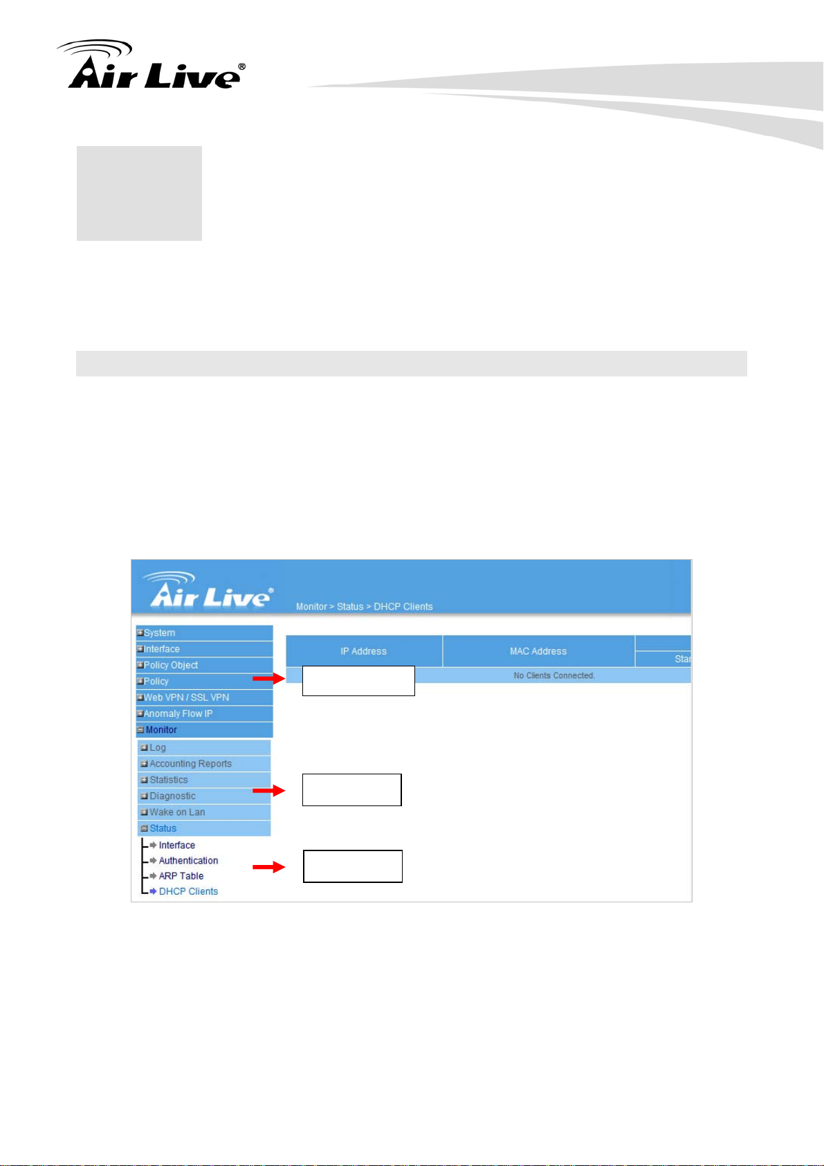
22.6 Status: You can find out the real-time status about Interface,
Authentication, ARP table, and DHCP Clients.
3 AirLive RS-2500 User’s Manual
Page 10

1. Introduction
1.3 Firmware Upgrade and Tech Support
If you encounter a technical issue that can not be resolved by information on this guide, we
recommend that you visit our comprehensive website support at www.airlive.com. The
tech support FAQ are frequently updated with latest information.
In addition, you might find new firmware that either increase software functions or provide
bug fixes for RS-2500. You can reach our on-line support center at the following link:
http://www.airlive.com/support/support_2.jsp
Since 2009, AirLive has added the “Newsletter Instant Support System” on our website.
AirLive Newsletter subscribers receives instant email notifications when there are new
download or tech support FAQ updates for their subscribed airlive models. To become an
AirLive newsletter member, please visit: http://www.airlive.com/member/member_3.jsp
Figure: AirLive Newsletter Support System
AirLive RS-2500 User’s Manual
4
Page 11

1. Introduction
1.4 Features
Web VPN/SSL VPN, IPSec and PPTP VPN Server
VPN Trunk
Application Blocking, IM / P2P Blocking, Content Blocking
User Authentication
QoS, Max. Bandwidth Per Source IP, Max. Concurrent Sessions Per Source IP
Dual WAN Load Balance and Fail-over
Multiple Subnet
Custom Service Definition for IP, TCP, UDP
Detect and block the anomaly flow IP
Policy based Firewall
DMZ Transparent
Schedule
Static Route, RIPv2
Web Management
5 AirLive RS-2500 User’s Manual
Page 12

2. Install the RS-2500
2. Installing the RS-2500
2
This section describes the hardware features and the hardware installation procedure for
the RS-2500. For software configuration, please go to chapter 3 for more details.
2.1 Before You Start
It is important to read through this section before you install the RS-2500
The RS-2500 comes with everything you need to start installation. You can use
CAT-5 Ethernet cable according to the length you need.
The RS-2500 must be installed with 5V adapter. Please do not use the other
voltage of adapter.
During upgrading firmware, please do not renew or close the webpage, otherwise
it could crash the firmware.
Please do not use FTP to transfer firmware file, because the firmware could be
transferred incompletely. If user upgrades RS-2500 with incomplete firmware it
will damage the device.
2.2 Package Content
The RS-2500 package contains the following items:
One RS-2500 main unit
One 5V 2.5A DC power adapter
2 x RJ-45 Ethernet Cable
User’s Guide CD
Quick Start Guide
AirLive RS-2500 User’s Manual
6
Page 13

2.3 Knowing your RS-2500
Below are descriptions and diagrams of the product:
2. Install the RS-2500
2.4 Hardware Installation
1. Plug in power adapter to RS-2500 and
electric
3. Wait for RS-2500 Status LED to stop
blinking the light
outlet at wall
2. Connect an Ethernet cable to PC and
RS-2500 LAN port
4. PC should get the IP address from RS-2500
DHCP server, and now you can login to
RS-2500 and configure the setting.
7 AirLive RS-2500 User’s Manual
Page 14
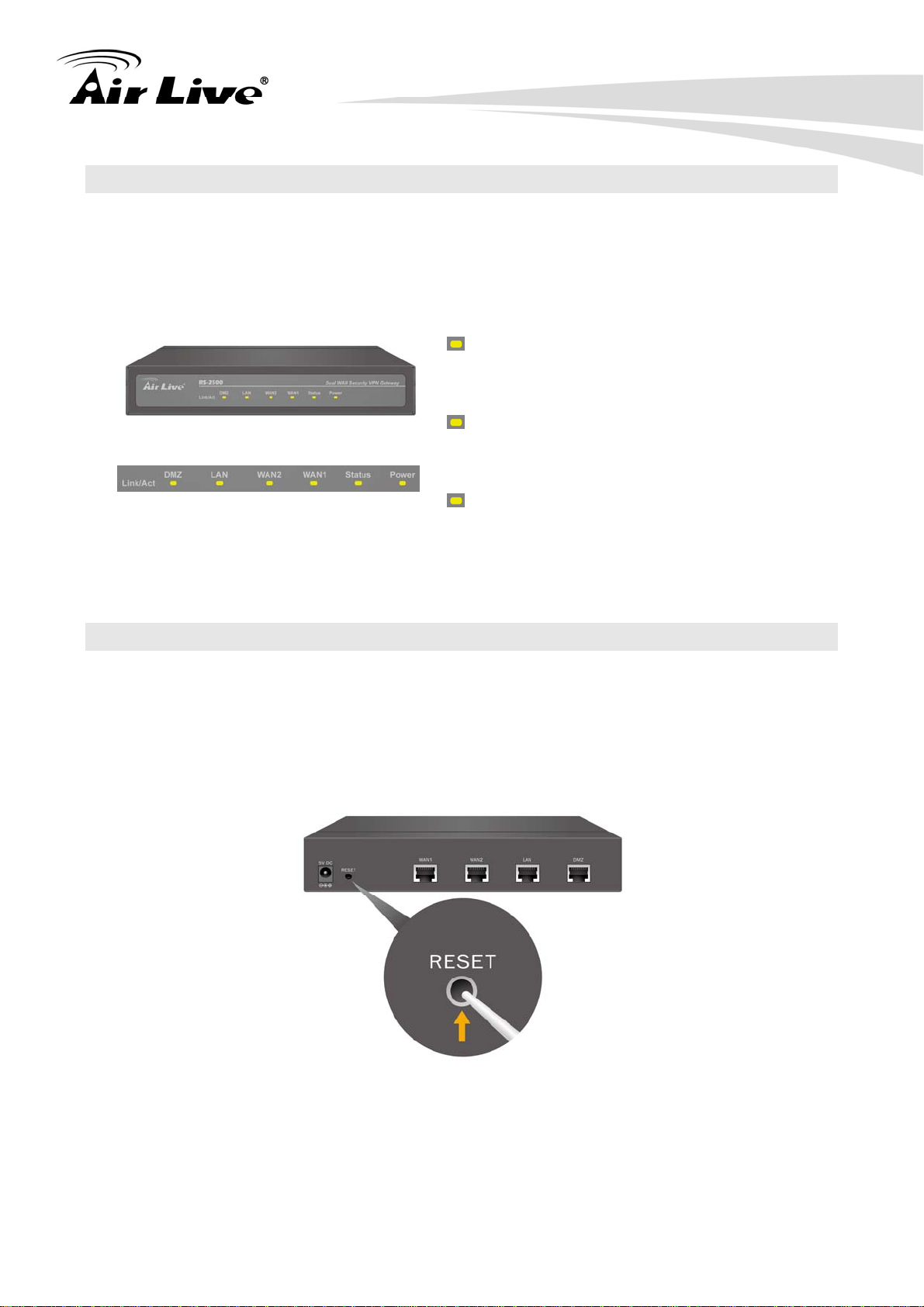
2.5 LED Table
This section describes the LED behavior of RS-2500.
You can find the LED on the Front side of the RS-2500.
Power
Steady Green – Power On device
OFF – No Power
Status
Steady Green – Ready to use
Blinking – At the booting process
WAN1/2, LAN, DMZ
Steady Green – Cable is connected
Blinking – Packets is sending/receiving
2. Install the RS-2500
2.6 Restore Settings to Default
If you have forgotten your RS-2500’s IP address or password, you can restore your
RS-2500 to the default settings by pressing on the “reset button” for more than 10 seconds.
You can find the reset button at back panel. Please see diagram below for details.
AirLive RS-2500 User’s Manual
8
Page 15

3. Configuring the RS-2500
3. Configuring the
3
To use this product correctly, you have to properly configure the network settings of your
computers and install the attached setup program into your MS Windows platform
(Windows 95/98/NT/2000/XP).
RS-2500
3.1 Important Information
The following information will help you to get start quickly. However, we recommend you
to read through the entire manual before you start. Please note the password are case
sensitive.
The default IP address is: 192.168.1.1 Subnet Mask: 255.255.255.0
The default user name is: admin
The default password is: airlive
After power on, please wait for 2 minutes for RS-2500 to finish boot up
3.2 Prepare your PC
The default IP address of this product is 192.168.1.1, and the default subnet mask is
255.255.255.0. These addresses can be changed on your need, but the default values are
used in this manual. If the TCP/IP environment of your computer has not yet been
configured, you can refer to the example:
1. Configure IP as 192.168.1.2, subnet mask as 255.255.255.0 and gateway as
192.168.1.1, or more easier,
2. Configure your computers to load TCP/IP setting automatically, that is, via DHCP
server of this product.
After installing the TCP/IP communication protocol, you can use the ping command to
check if your computer has successfully connected to this product. The following example
shows the ping procedure for Windows platforms. First, execute the ping command
ping 192.168.1.1
9 AirLive RS-2500 User’s Manual
Page 16

3. Configuring the RS-2500
If the following messages appear:
Pinging 192.168.1.1 with 32 bytes of data:
Reply from 192.168.1.1: bytes=32 time=2ms TTL=64
A communication link between your computer and this product has been successfully
established. Otherwise, if you get the following messages,
Pinging 192.168.1.1 with 32 bytes of data:
Request timed out.
There must be something wrong in your installation procedure. You have to check the
following items in sequence:
1. Is the Ethernet cable correctly connected between this product and your computer?
Tip: The LAN LED of this product and the link LED of network card on your computer must
be lighted.
2. Is the TCP/IP environment of your computers properly configured?
Tip: If the IP address of this product is 192.168.1.1, the IP address of your computer must
be 192.168.1.X and default gateway must be 192.168.1.1.
3.3 Management Interface
The RS-2500 can be configured using one the management interfaces below:
Web Management (HTTP): You can manage your RS-2500 by simply typing its IP
address in the web browser. We recommend using this interface for initial
configurations. To begin, simply enter RS-2500 IP address (default is 192.168.1.1) on
the web browser. The default password is “airlive”.
Secure Web Management (HTTPS): HTTPS is also using web browser for
configuration. But all the data transactions are securely encrypted using SSL
encryption. Therefore it is safe and easy way to manage your RS-2500.
AirLive RS-2500 User’s Manual
10
Page 17
3. Configuring the RS-2500
3.4 Introduction to Web Management
The RS-2500 offers both normal (http) and secured (https) Web Management interfaces.
Their share the same interface and functions, and they can both be accessed through web
browsers. The only difference is HTTPS are encrypted for extra security. Therefore, we
will discuss them together as “Web Management” on this guide.
If you are placing the RS-2500 behind router or firewall, you might need to open virtual
server ports to RS-2500 on your firewall/router
HTTP: TCP Port 80
HTTPS: TCP/UDP Port 443
3.4.1 Getting into Web Management
Normal Web Management (HTTP)
To get into the Normal Web Management, simply type in the RS-2500’s IP address (default
IP is 192.168.1.1) into the web browser’s address field.
11 AirLive RS-2500 User’s Manual
Page 18
3. Configuring the RS-2500
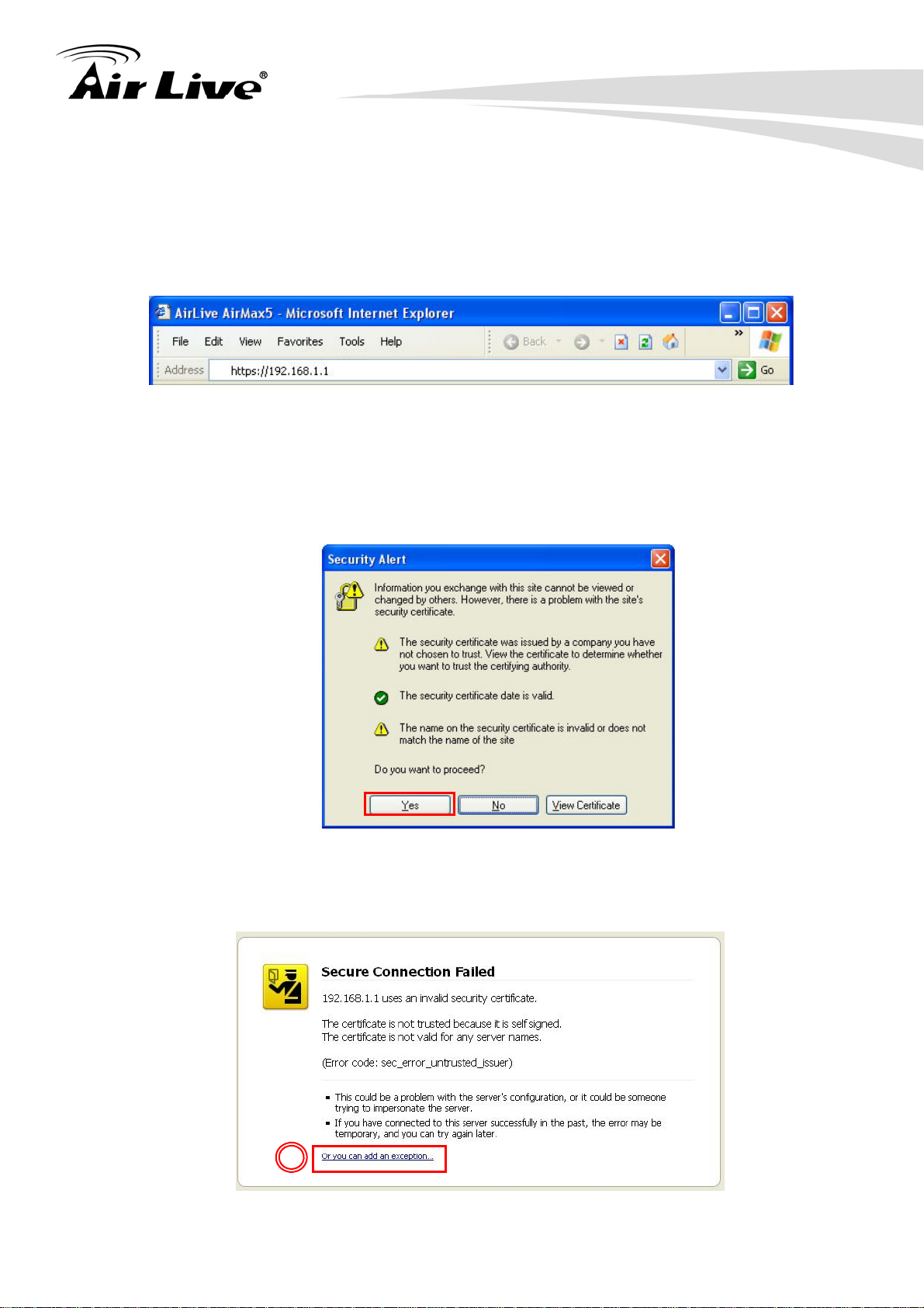
Secured Web Management (HTTPS)
To get into the Secured Web Management, just type “https://192.168.1.1” into the web
browser’s address field. The “192.168.1.1” is RS-2500’s default IP address. If the IP
address is changed, the address entered in the browser should change also.
A security warning screen from your browser will then pop-up depending on the browser
you use. Please follow step below to clear the security screen.
Internet Explorer: Select “Yes” to proceed
Firefox:
1. Select “or you can add an exception”
1
AirLive RS-2500 User’s Manual
12
Page 19
3. Configuring the RS-2500
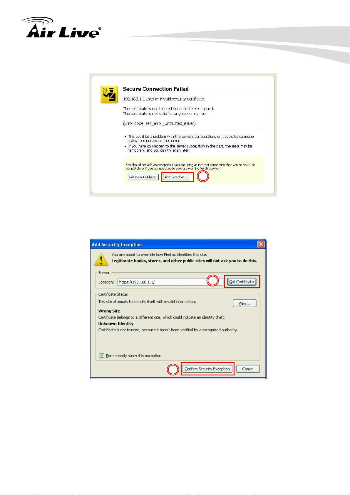
2. Click on “Add Exception”
2
3. Click on “Get Certificate”. Then, please enter RS-2500’s IP address. Finally,
please click on “Confirm Security Exception.”
3
4
13 AirLive RS-2500 User’s Manual
Page 20
3. Configuring the RS-2500
3.5 Initial Configurations
We recommend users to browse through RS-2500’s web management interface to get an
overall picture of the functions and interface. Below are the recommended initial
configurations for first time login:
STEP 1:
1. Connect the Admin’s PC and the LAN port of the Security VPN Gateway.
2. Open an Internet web browser and type the default IP address of the Security VPN
Gateway as 192.168.1.1 in the address bar.
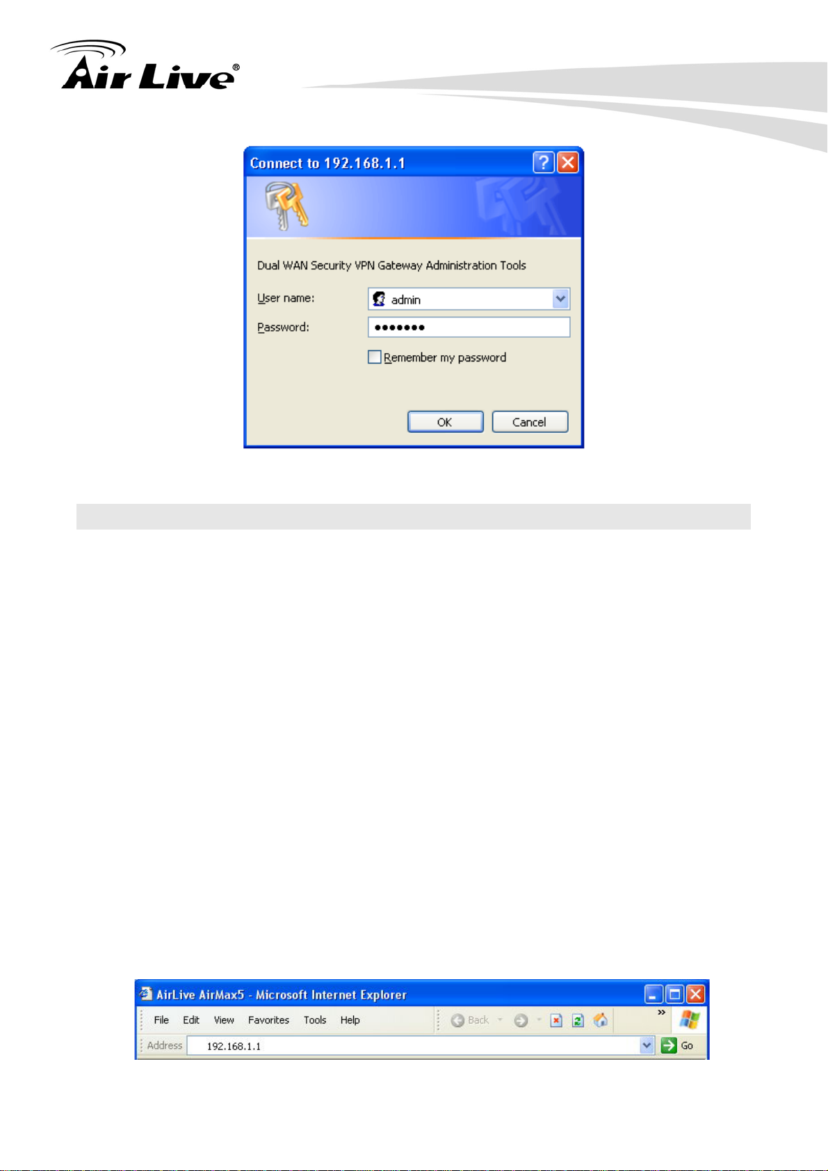
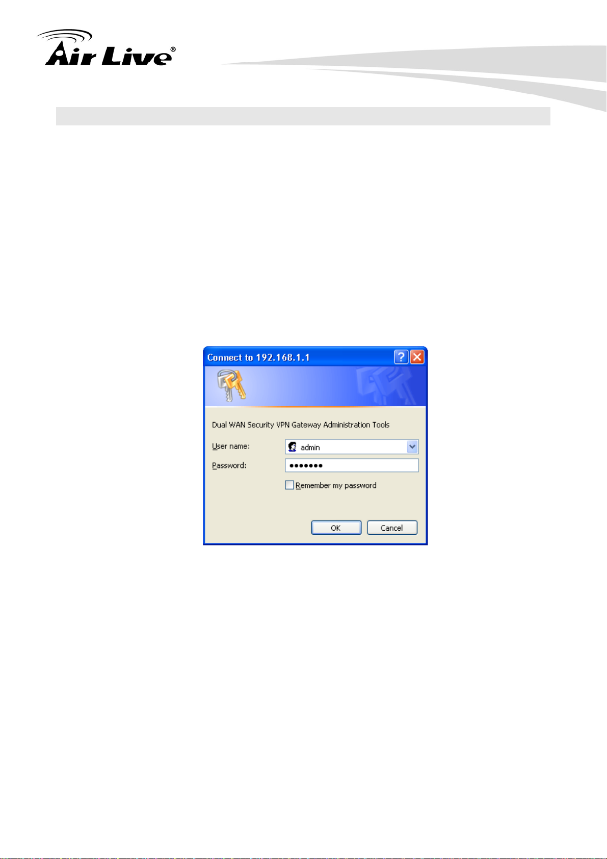
3. A pop-up screen will appear and prompt for a username and password. Enter the
default login username (admin) and password (airlive) of Administrator.
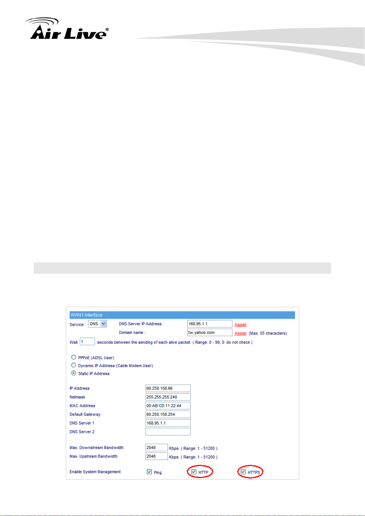
STEP 2:
After entering the username and password, the Security VPN Gateway WEB UI screen will
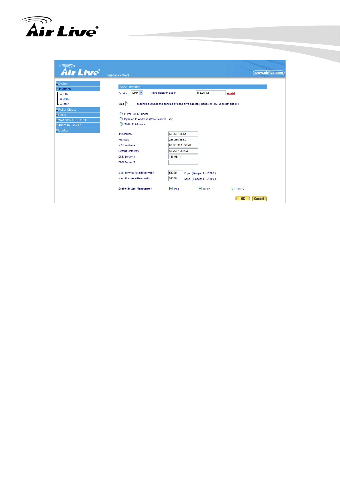
display. Select the Interface tab on the left menu and a sub-function list will be displayed.
Click on WAN from the sub-function list, enter proper the network setup information
Click Modify to modify WAN1/2 settings (i.e. WAN1 Interface)
WAN1 interface IP Address 60.250.158.64
NetMask 255.255.255.0
Default Gateway 60.250.158.254
DNS Server1 168.95.1.1
AirLive RS-2500 User’s Manual
14
Page 21
3. Configuring the RS-2500
STEP 3:
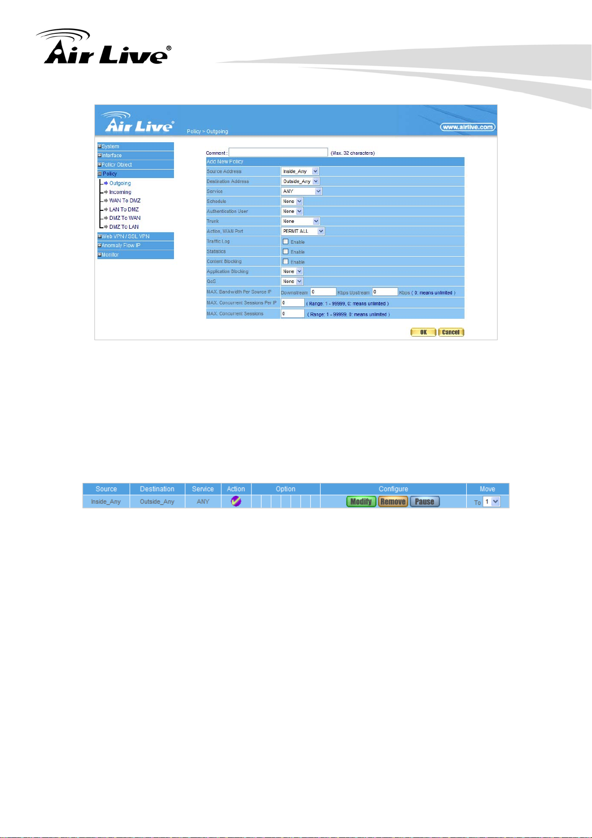
Click on the Policy tab from the main function menu, and then click on Outgoing from the
sub-function list.
STEP 4:
Click on New Entry button.
STEP 5:
When the New Entry option appears, enter the following configuration:
Source Address – select Inside_Any
Destination Address – select Outside_Any
Service - select ANY
Action - select Permit ALL
Click on OK to apply the changes.
15 AirLive RS-2500 User’s Manual
Page 22
3. Configuring the RS-2500
STEP 6:
The configuration is successful when the screen below is displayed. Make sure that all the
computers that are connected to the LAN port have their Default Gateway IP Address set to
the Security VPN Gateway’s LAN IP Address (i.e. 192.168.1.1). At this point, all the
computers on the LAN network should gain access to the Internet immediately.
AirLive RS-2500 User’s Manual
16
Page 23
4. Web Management
4. Web Management
4
In this chapter, we will explain about the Administration settings in web management
interface. Please be sure to read through Chapter 3’s “Introduction to Web Management”
and “Initial Configurations” first.
4.1 About RS-2500’s Menu Structure
The RS-2500’s web management menu is divided into 7 main subjects: System, Interface,
Policy Object, Policy, Web VPN / SSL VPN, Anomaly IP Flow, and Monitor. Each subject
includes several sub-object settings, and each sub-object also includes several functions
for user’s configuration.
RS-2500 was designed as the policy based firewall, it means user should configure Policy
Object setting, and enable the function at Policy.
Main Subject
Sub-Object
Functions
System: It includes Administration, Configure, and Logout sub-objects. The
System subject allows you configuring basic setting of the RS-2500. Please refer to
chapter 5 Administration and chapter 6 Configure.
Interface: It includes WAN, LAN and DMZ sub-objects. For more configuration
information please refer to chapter 7.
AirLive RS-2500 User’s Manual
18
Page 24
4. Web Management
Policy Object: It includes Address, Service, Schedule, QoS, Authentication,
Content Blocking, Application Blocking, Virtual Server, and VPN sub-objects.
Before to enable the function at Policy, you need to configure the Policy Object
setting first. Please refer to chapter 8 ~ 17.
Policy: It includes Outgoing, Incoming, WAN To DMZ, LAN To DMZ, DMZ To
WAN, and DMZ To LAN sub-objects. Please make sure to Logout after you finish
all settings. You must configure Policy setting to enable the Policy Object settings.
Please refer to chapter 18.
Web VPN / SSL VPN: RS-2500 provides Web VPN / SSL VPN function to allow
remote user connecting and accessing to router’s LAN resource. Please refer to
chapter 20.
Anomaly IP Flow: It works to define the rule to block hacker from Internet or
Intranet. Please refer to chapter 21.
Monitor: It includes Log, Accounting Report, Statistic, Diagnostic, Wake on Lan,
and Status sub-objects. The function works to offer the report or log for user to
realize device and network’s current status. Please refer to chapter 22.
4.2 Remote Web Management
RS-2500 allows you accessing the web management page from remote site, and you can
choose to use HTTP or HTTPS. In Interface WAN, enable HTTP or HTTPS or both.
19 AirLive RS-2500 User’s Manual
Page 25
5. Administration
5. Administration
5
“System” is the managing of settings such as the privileges of packets that pass through
the RS-2500 and monitoring controls. The System Administrators can manage, monitor,
and configure RS-2500 settings. But all configurations are “read-only” for all users other
than the System Administrator; those users are not able to change any setting of the
RS-2500.
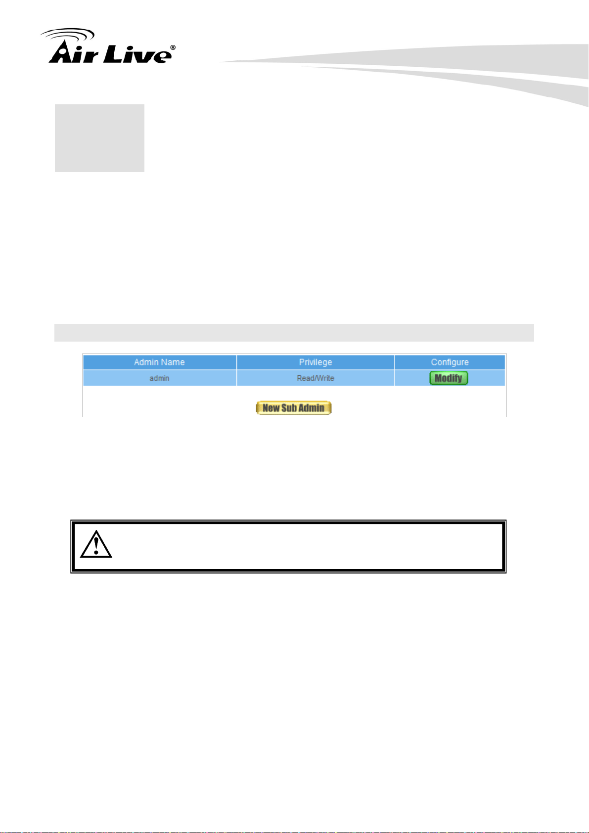
5.1 Admin
Admin Name: The username of Administrators and Sub Administrator for the RS-2500.
The admin user name cannot be removed; and the sub-admin user can be removed or
modified.
The default Account: admin; Password: airlive
Privilege: The privileges of Administrators (Admin or Sub Admin). The username of
the main Administrator is Administrator with reading / writing privilege. Administrator
also can change the system setting, log system status, and to increase or delete
sub-administrator. Sub-Admin may be created by the Admin by clicking New Sub
Admin. Sub Admin have only read and monitor privilege and cannot change any
system setting value.
Configure: Click Modify to change the “Sub-Administrator’s” password or click
Remove to delete a “Sub Administrator.”
AirLive RS-2500 User’s Manual
20
Page 26
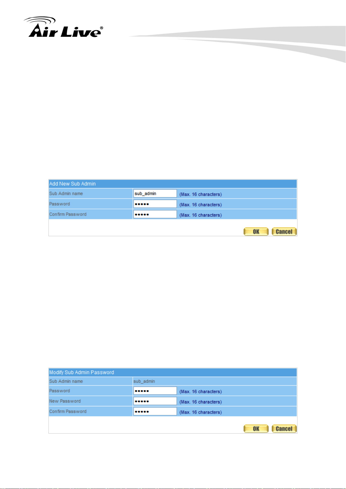
Adding a new Sub Administrator
5. Administration
STEP 1
STEP 2
STEP 3
﹒
In the Admin WebUI, click the New Sub Admin button to create a new Sub
Administrator.
﹒
In the Add New Sub Administrator WebUI (Figure 5-1) and enter the following
setting:
Sub Admin Name: sub_admin
Password: 12345
Confirm Password: 12345
﹒
Click OK to add the user or click Cancel to cancel it.
Figure 5-1 Add New Sub Admin
Modify the Administrator’s Password
STEP 1
﹒
In the Admin WebUI, locate the Administrator name you want to edit, and click on
Modify in the Configure field.
STEP 2
﹒
The Modify Administrator Password WebUI will appear. Enter the following
information:
Password: admin
New Password: 52364
Confirm Password: 52364 (Figure 5-2)
STEP 3
﹒
Click OK to confirm password change.
Figure 5-2 Modify Admin Password
21 AirLive RS-2500 User’s Manual
Page 27
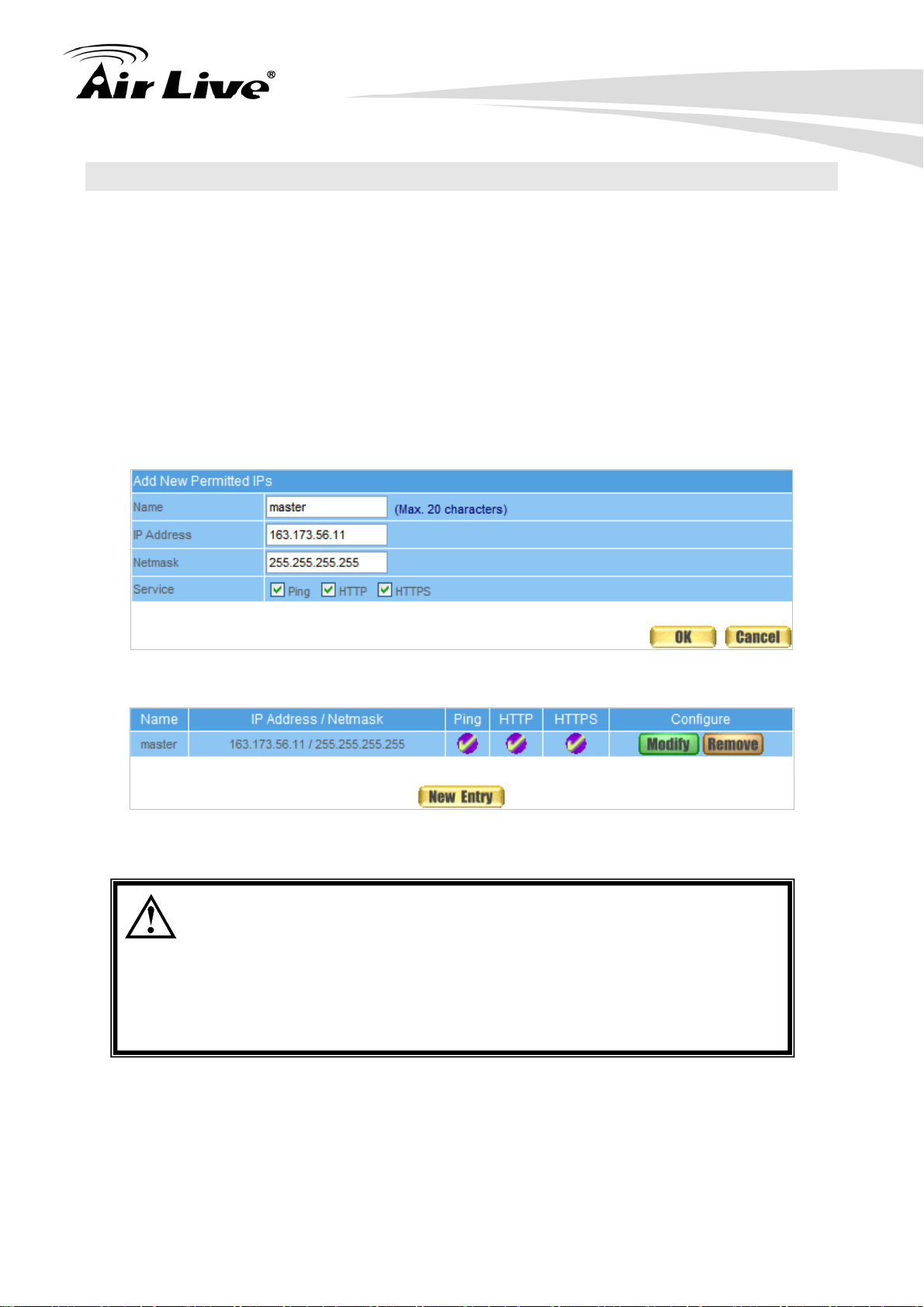
5.2 Permitted IP
Add Permitted IPs
5. Administration
STEP 1
﹒
Add the following setting in Permitted IPs of Administration: (Figure 5-3)
Name: Enter master
IP Address: Enter 163.173.56.11
Netmask: Enter 255.255.255.255
Service: Select Ping, HTTP and HTTPS
Click OK
Complete add new permitted IPs (Figure 5-4)
Figure 5-3 Setting Permitted IPs WebUI
To make Permitted IPs be effective, it is suggested to cancel the Ping,
HTTP, and HTTPS selection in LAN, WAN, or DMZ Interface setting.
Before canceling the WebUI selection of Interface, user must set up
the Permitted IPs first, otherwise, it would cause the situation that
user cannot enter WebUI by appointed Interface.
AirLive RS-2500 User’s Manual
Figure 5-4 Complete Add New Permitted IPs
22
Page 28
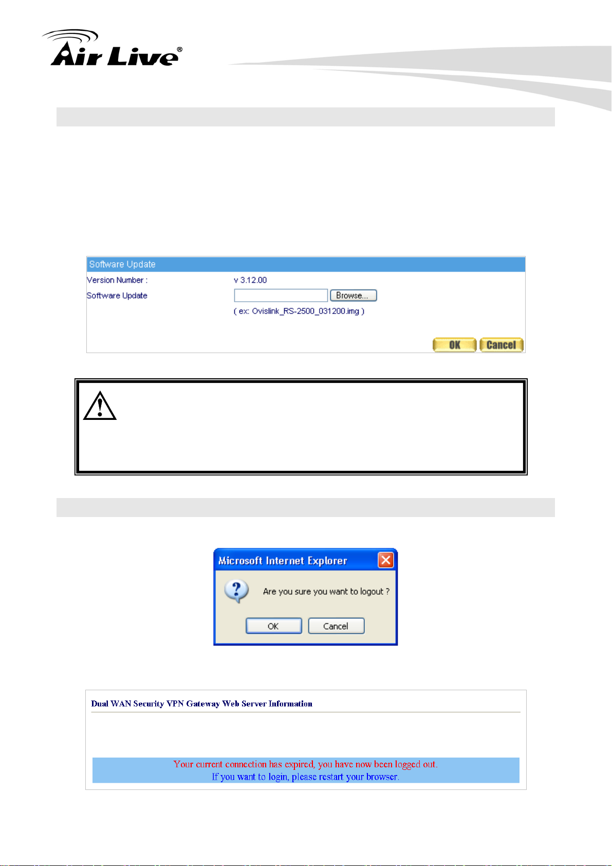
5.3 Software Update
5. Administration
STEP 1
﹒
Select Software Update in System, and follow the steps below:
To obtain the version number from Version Number and obtain the latest
version from Internet. And save the latest version in the hardware of the PC,
which manage the RS-2500
Click Browse and choose the latest software version file.
Click OK and the system will update automatically. (Figure 5-5)
Figure 5-5 Software Update
It takes 4 minutes to update software. The system will reboot after
update. During the updating time, please don’t turn off the PC or close
WebUI. It may cause some unexpected mistakes. (Strong suggests
updating the software from LAN to avoid unexpected mistakes.)
5.4 Logout
STEP 1
STEP 2
﹒
Click Logout in System to protect the system while admin is away. (Figure 5-6)
﹒
Click OK and the logout message will appear in WebUI. (Figure 5-7)
Figure 5-6 Confirm Logout WebUI
Figure 5-7 Logout WebUI Message
23 AirLive RS-2500 User’s Manual
Page 29
6. Configure
6. Configure
6
The Configure is according to the basic setting of the RS-2500. In this chapter the definition
is Setting, Date/Time, Multiple Subnet, Route Table, DHCP, Dynamic DNS, Hosts Table,
and Language settings.
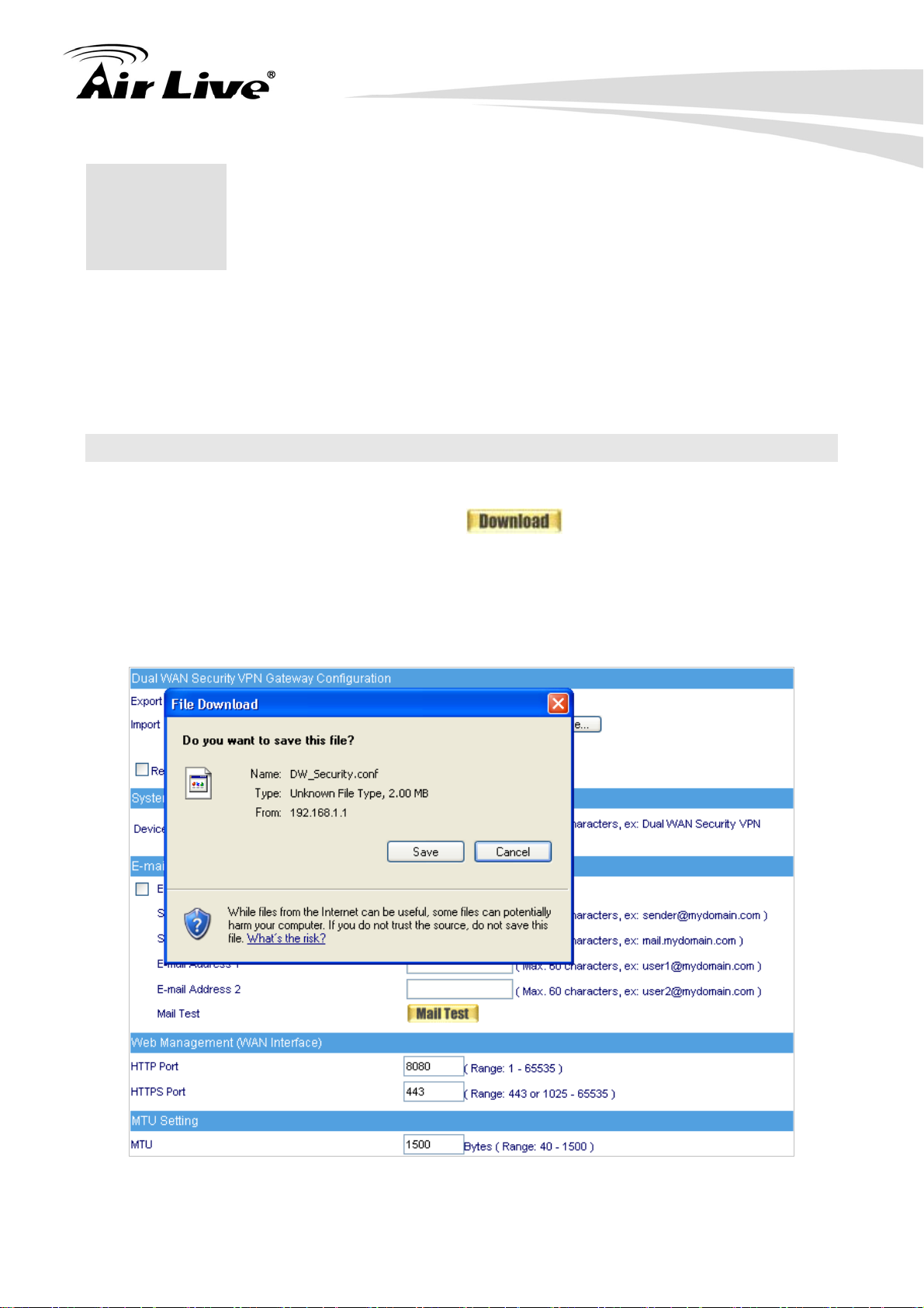
6.1 Setting
System Settings- Exporting
STEP 1
STEP 2
﹒
In System Setting WebUI, click on button next to Export System
Setting to Client.
﹒
When the File Download pop-up window appears, choose the destination place
where to save the exported file and click on Save. The setting value of RS-2500
will copy to the appointed site instantly. (Figure 6-1)
Figure 6-1 Select the Destination Place to Save the Exported File
AirLive RS-2500 User’s Manual
24
Page 30
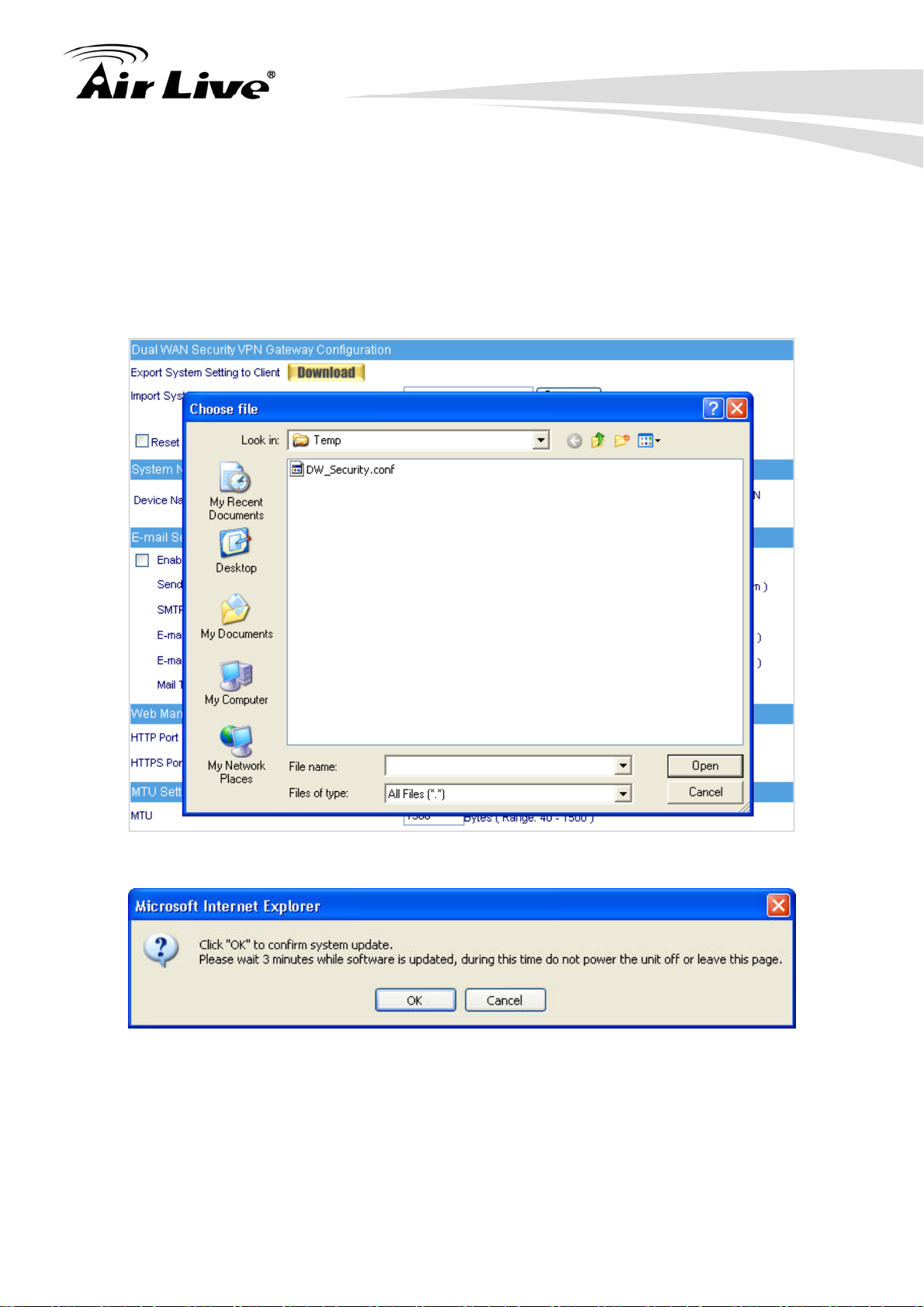
System Settings- Importing
6. Configure
STEP 1
STEP 2
﹒
In System Setting WebUI, click on the Browse button next to Import System
Setting from Client. When the Choose File pop-up window appears, select the file
to which contains the saved RS-2500 Settings, then click OK. (Figure 6-2)
﹒
Click OK to import the file into the RS-2500 (Figure 6-3)
Figure 6-2 Enter the File Name and Destination of the Imported File
Figure 6-3 Upload the Setting File WebUI
25 AirLive RS-2500 User’s Manual
Page 31

Restoring Factory Default Settings
6. Configure
STEP 1
STEP 2
﹒
Select Reset System to Factory Setting in RS-2500 Configuration WebUI
﹒
Click OK at the bottom-right of the page to restore the factory settings. (Figure 6-4)
Figure 6-4 Reset Factory Settings
Email Settings
Select Enable E-mail Alert Notification under E-mail Settings. This function will enable
the RS-2500 to send e-mail alerts to the System Administrator when the network is being
attacked by hackers or when emergency conditions occur . (It can be set from Anomaly Flow
IP Setting to detect Hacker Attacks)
Enabling E-mail Alert Notification
STEP 1
STEP 2
STEP 3
STEP 4
STEP 5
﹒
Select Enable E-mail Alert Notification under E-Mail Settings.
﹒
Sender Address (Required by some ISPs): Enter the Sender Address.
﹒
SMTP Server IP: Enter SMTP server’s IP address
﹒
E-Mail Address 1: Enter the e-mail address of the first user to be notified.
﹒
E-Mail Address 2: Enter the e-mail address of the second user to be notified.
(Optional)
STEP 6
﹒
Click OK on the bottom-right of the screen to enable E-mail Alert Notification.
(Figure 6-5)
AirLive RS-2500 User’s Manual
26
Page 32

6. Configure
A
Figure 6-5 Enable E-mail Alert Notification
Click on Mail Test to test if E-mail Address 1 and E-mail Address 2
can receive the Alert Notification correctly.
Web Management (WAN Interface)
The System Manager can change the port number used by HTTP or HTTPS port anytime.
(Remote WebUI management)
fter HTTP port has changed, if the administrator wants to enter
WebUI from WAN, will have to change the port number of browser.
(For example: http://61.62.108.172:8080
)
MTU Setting
It provides the Administrator to modify the networking package length anytime. Its default
value is 1500 Bytes.
Link Speed / Duplex Mode Setting
By this function can set the transmission speed and mode of WAN Port when connecting
other device.
Dynamic Routing (RIPv2)
Select to enable the function of AirLive RS-2500 LAN, WAN1, WAN2 or DMZ Port to
send/receive RIPv2 packets, and communication between Internal Router or External
Router, to update Dynamic Routing.
27 AirLive RS-2500 User’s Manual
Page 33

6. Configure
SIP protocol pass-through
Select to enable the function of RS-2500 of passing SIP protocol. It is also possible that the
SIP protocol can pass through RS-2500 without enabling this function depends on the SIP
device’s type you have.
Administration Packet Logging
After enable this function, the RS-2500 will record packet which source or destination IP
address is RS-2500, and record in Traffic Log for System Manager to inquire about.
System Reboot
Once this function is enabled, the RS-2500 will be rebooted.
STEP 1
﹒
Reboot RS-2500:Click Reboot button next to Reboot RS-2500 Appliance.
STEP 2
STEP 3
﹒
A confirmation pop-up page will appear.
﹒
Follow the confirmation pop-up page; click OK to restart RS-2500.
(Figure 6-6)
AirLive RS-2500 User’s Manual
Figure 6-6 The else Function Settings
28
Page 34

6. Configure
6.2 Date/Time
Synchronize system clock
The administrator can configure the RS-2500’s date and time by either syncing to an
Internet Network Time Server (NTP) or by syncing to your computer’s clock.
STEP 1
STEP 2
STEP 3
STEP 4
STEP 5
﹒
Select Enable synchronize with an Internet time Server (Figure 6-7)
﹒
Click the down arrow to select the offset time from GMT.
﹒
If necessary, select Enable daylight saving time setting
﹒
Enter the Server IP / Name with which you want to synchronize.
﹒
Set the interval time to synchronize with outside servers.
Figure 6-7 System Time Setting
Click on the Sync button and then the RS-2500’s date and time will be
synchronized to the Administrator’s PC.
The value of Set Offset hours From GMT and Server IP / Name can
be looking for from Assist.
29 AirLive RS-2500 User’s Manual
Page 35

6. Configure
6.3 Multiple Subnet
Connect to the Internet through Multiple Subnet NAT or Routing Mode by the IP address
that set by the LAN user’s network card. (Figure 6-8)
Figure 6-8 Multiple Subnet UI
WAN Interface IP / Forwarding Mode
The WAN IP address corresponds with Multiple Subnet
The system mode of Multiple Subnet (NAT mode or Routing Mode)
Interface
The interface of Multiple Subnet (LAN or DMZ)
Alias IP of Interface / Netmask
The Multiple Subnet IP address range setting
Configuration Example
RS-2500 WAN1 (10.10.10.1) connect to the ISP Router (10.10.10.2) and the subnet that
provided by ISP is 162.172.50.0/24
To connect to Internet, WAN2 IP (211.22.22.22) connects with ATUR.
Adding Multiple Subnet
Add the following settings in Multiple Subnet of System function:
Click on New Entry
Alias IP of LAN Interface: Enter 162.172.50.1
Netmask:Enter 255.255.255.0
WAN1: Choose Routing in Forwarding Mode, and press Assist to select
Interface IP 1010.10.1.
WAN2:Enter Interface IP 211.22.22.22, and choose NAT in Forwarding
Mode
Click OK
Complete Adding Multiple Subnet (Figure 6-9)
AirLive RS-2500 User’s Manual
30
Page 36

6. Configure
A
Figure 6-9 Add Multiple Subnet WebUI
WAN1 and WAN2 Interface can use Assist to enter the data.
fter setting, there will be two subnets in LAN: 192.168.1.0/24 (default
LAN subnet) and 162.172.50.0/24. So if LAN IP is:
192.168.1.xx, it must use NAT Mode to access to the Internet.
(In Policy it only can setup to access to Internet by WAN2. If by WAN1
Routing mode, then it cannot access to Internet by its virtual IP)
162.172.50.xx, it uses Routing mode through WAN1 (The Internet
Server can see your IP 162.172.50.xx directly). And uses NAT mode
through WAN2 (The Internet Server can see your IP as WAN2 IP)
31 AirLive RS-2500 User’s Manual
Page 37

6. Configure
NAT Mode
It allows Internal Network to set multiple subnet address and connect with the Internet
through different WAN IP Addresses.
For example, the lease line of a company applies several real IP Addresses 168.85.88.0/24,
and the company is divided into Service, Sales, Procurement, and Accounting
department, the company can distinguish each department by different subnet for the
purpose of managing conveniently. The settings are as the following:
1. R&D department subnet:192.168.1.1/24 (LAN) 168.85.88.253 (WAN)
2. Service department subnet:192.168.2.1/24 (LAN) 168.85.88.252 (WAN)
3. Sales department subnet:192.168.3.1/24 (LAN) 168.85.88.251 (WAN)
4. Procurement department subnet:192.168.4.1/24 (LAN) 168.85.88.250 (WAN)
5. Accounting department subnet:192.168.5.1/24 (LAN) 168.85.88.249 (WAN)
The first department (R&D department) had set while setting interface IP; the other four
ones have to be added in Multiple Subnet. After completing the settings, each department
uses the different WAN IP Address to connect to the Internet. The settings of each
department are as following:
Service Sales Procurement Accounting
IP Address 192.168.2.2~254 192.168.3.2~254 192.168.4.2~254 192.168.5.2~254
Subnet
255.255.255.0 255.255.255.0 255.255.255.0 255.255.255.0
Netmask
Gateway 192.168.2.1 192.168.3.1 192.168.4.1 192.168.5.1
Routing Mode
It is the same as NAT mode approximately but does not have to correspond to the real
WAN IP address, which let internal PC to access to Internet by its own IP. (External user
also can use the IP to connect with the Internet)
AirLive RS-2500 User’s Manual
32
Page 38

6. Configure
6.4 Route Table
Route Table works to connect RS-2500 with another router, and make those users with
different IP subnet can access Internet at the same time. (Figure 6-10, 11)
Figure 6-10 Route Table UI
Figure 6-11 Route Table UI
Destination IP / Netmask
The target IP subnet of routing rule
Gateway
Indicate the IP address of router that will route packets to target subnet
Interface
Indicate the interface to send out the routing packets
33 AirLive RS-2500 User’s Manual
Page 39

6.5 DHCP
Subnet
The domain name of LAN
NetMask
The LAN Netmask
Gateway
The default Gateway IP address of LAN
Broadcast IP
The Broadcast IP of LAN
6. Configure
STEP 1
﹒
Select DHCP in System and enter the following settings:
DHCP Relay Interface: Select the interface connected to WAN DHCP server
DHCP Server IP: Enter the IP address of DHCP server
Domain Name: Enter the Domain Name
DNS Server 1: Enter the distributed IP address of DNS Server1.
DNS Server 2: Enter the distributed IP address of DNS Server2.
WINS Server 1: Enter the distributed IP address of WINS Server1.
WINS Server 2: Enter the distributed IP address of WINS Server2.
LAN Interface:
Client IP Address Range 1:
Enter the starting and the ending IP address dynamically assigning to
DHCP clients. The default value is 192.168.1.2 to 192.168.1.254 (it must
be in the same subnet)
Client IP Address Range 2:
Enter the starting and the ending IP address dynamically assigning to
DHCP clients. But it must be within the same subnet as Client IP
Address Range 1 and the range cannot be repeated.
DMZ Interface: the same as LAN Interface. (DMZ works only if to enable DMZ
Interface)
Leased Time: Enter the leased time for Dynamic IP. The default time is 24 hours.
Click OK and DHCP setting is completed. (Figure 6-12)
AirLive RS-2500 User’s Manual
34
Page 40

6. Configure
A
Figure 6-12 DHCP WebUI
When selecting Automatically Get DNS, the DNS Server will be
locked as LAN Interface IP. (Using Occasion: When the system
dministrator starts Authentication, the users’ first DNS Server must
be the same as LAN Interface IP in order to enter Authentication
WebUI)
35 AirLive RS-2500 User’s Manual
Page 41

6.6 Dynamic DNS
6. Configure
STEP 1
﹒
Select Dynamic DNS in System function (Figure 6-13). Click New Entry button
Service providers:Select service providers.
Automatically fill in the WAN 1/2 IP:Check to automatically fill in the W AN
1/2 IP.
User Name:Enter the registered user name.
Password:Enter the password
Domain name:Enter Your host domain name
Click OK to add Dynamic DNS. (Figure 6-14)
Figure 6-13 DDNS WebUI
Chart
Meaning
successfully
If System Administrator had not registered a DDNS account, click on
Sign up then can enter the website of the provider.
If you do not select Automatically in WAN IP and then you can enter
a specific IP in WAN IP. DDNS corresponds to that specific IP
address.
AirLive RS-2500 User’s Manual
Figure 6-14 Complete DDNS Setting
Update
Incorrect username
or password
36
Connecting to
server
Unknown error
Page 42

6. Configure
6.7 Host Table
Host Name
It can be set by System Manager, to allow internal user accessing the information provided
by the host of the domain.
Virtual IP Address
The virtual IP address is corresponding to the Host. It must be LAN or DMZ IP address.
STEP 1
﹒
Select Host Table in Settings function and click on New Entry
Host Name: The domain name of the server
Virtual IP Address: The virtual IP address is corresponding to the Host.
Click OK to add Host Table. (Figure 6-15)
To use Host Table, the user PC’s first DNS Server must be the same
as the LAN Port or DMZ Port IP of RS-2500. That is, the default
gateway.
6.8 Language
Figure 6-15 Add New Host Table
Select the Language version (English Version/ Traditional Chinese Version or
Simplified Chinese Version) and click OK. (Figure 6-16)
Figure 6-16 Language Setting WebUI
37 AirLive RS-2500 User’s Manual
Page 43

7. Interface
7. Interface
7
In this chapter, you can set up the IP addresses for the office network, and you may also
configure the IP addresses of the LAN network, the WAN1 and WAN2 network, and the
DMZ network.
The Netmask and gateway IP addresses are also configured in this chapter.
Define the required fields of Interface
LAN: Using the LAN Interface, the Administrator can set up the LAN network of
RS-2500
WAN: The System Administrator can set up the WAN network of RS-2500.
Connection Test: The function works to identify WAN port’s connection
status. The testing ways are as following:
ICMP:User can define the IP address and RS-2500 will ping the
address to verify WAN port’s connection status.
DNS:Another way to verify the connection status by checking the
DNS server and Domain Name configured by user.
Upstream/Downstream Bandwidth: The System Administrator can set
up the correct Bandwidth of WAN network Interface here.
Auto Disconnect: The PPPoE connection will automatically disconnect
after a length of idle time (no activities). Enter “0” means the PPPoE
connection will not disconnect at all.
DMZ: The Administrator uses the DMZ Interface to set up the DMZ network.
NAT Mode:In this mode, the DMZ is an independent virtual subnet. This
virtual subnet can be set by the Administrator but cannot be the same as
LAN Interface
Transparent Mode: In this mode, the DMZ and WAN Interface are in the
same subnet
AirLive RS-2500 User’s Manual
38
Page 44

Balance Mode
Auto: The RS-2500 will adjust the WAN 1/2 utility rate automatically according to
the downstream/upstream of WAN. (For users who are using various download
bandwidth)
Round-Robin: The RS-2500 distributes the WAN 1/2 download bandwidth 1:1, in
other words, it selects the agent by order. (For users who are using same
download bandwidths)
By Traffic: The RS-2500 distributes the WAN 1/2 download bandwidth by
accumulative traffic
By Session: The RS-2500 distributes the WAN 1/2 download bandwidth by
saturated connections
By Packet: The RS-2500 distributes the WAN 1/2 download bandwidth by
7. Interface
accumulated packets and saturated connection
By Source IP: The RS-2500 distributes the WAN 1/2 connection by source IP
address, once the connection is built up, all the packets from the same source IP
will pass through the same WAN interface
By Destination IP: The RS-2500 will allocate the WAN connection corresponding
to the destination IP, once the connection is built up, all the packets to the same
destination IP will pass through the same WAN interface. The connection will be
re-assigned with WAN interface when the connections are stopped.
Connect Mode
Display the current connection mode
PPPoE (ADSL user)
Dynamic IP Address (Cable Modem User)
Static IP Address
PPTP (European User Only)
Saturated Connections
Set the number for saturation whenever session numbers reach it, the RS-2500
switches to the next agent on the list
Ping: Select this function to allow the LAN users to ping the Interface IP Address.
HTTP: Select to enable the user to enter the WebUI of RS-2500 from Interface IP.
HTTPS: Select to enable the user to enter the secure WebUI of RS-2500 from Interface
IP.
Priority
Set priority of WAN for Internet Access
39 AirLive RS-2500 User’s Manual
Page 45

7.1 LAN
Modify LAN Interface Settings
7. Interface
STEP 1
﹒
Select LAN in Interface and enter the following setting:
Enter the new IP Address and Netmask
Select Ping, HTTP and HTTPS
Click OK (Figure 7-1)
Figure 7-1 Setting LAN Interface WebUI
The default LAN IP Address is 192.168.1.1. After the Administrator
setting the new LAN IP Address on the computer, he/she have to
restart the System to make the new IP address effective. (when the
computer obtain IP by DHCP)
Do not cancel WebUI selection before not setting Permitted IPs yet,
because the Administrator cannot be allowed to enter the RS-2500
WebUI from LAN.
AirLive RS-2500 User’s Manual
40
Page 46

7.2 WAN
WAN Interface Address Setting
7. Interface
STEP 1
STEP 2
﹒
Select WAN in Interface and click Modify in WAN1 Interface. (Figure 7-2)
Figure 7-2 Setting WAN Interface WebUI
﹒
Setting the Connection Service (ICMP or DNS way):
ICMP:Enter an Alive Indicator Site IP (can select from Assist) (Figure 7-3)
DNS:Enter two different DNS Server IP Address and Domain Name (can
select from Assist) (Figure 7-4)
Setting time of seconds between sending alive packet.
Figure 7-3 ICMP Connection
Figure 7-4 DNS Service
Connection test is used for RS-2500 to detect if the WAN can connect
or not. So the Alive Indicator Site IP, DNS Server IP Address, or
Domain Name must be able to use permanently. Or it will cause
judgmental mistakes of the device.
41 AirLive RS-2500 User’s Manual
Page 47

7. Interface
STEP 3
﹒
Select the Connecting way:
PPPoE (ADSL User) (Figure 7-5):
1. Select PPPoE
2. Enter User Name and Password information provided by ISP.
4. Select Dynamic or Fixed in IP Address provided by ISP.
If you select Fixed, please enter IP Address, Netmask, and Default Gateway.
5. Enter Max. Downstream Bandwidth and Max. Upstream Bandwidth
(According to the flow that user applies)
6. Enter the value on the setting of “Auto Disconnect if idle for □ minutes
(Range: 1-99999, 0 means always connected)”, the default value is 0
(Always connected).
7. Select Ping, HTTP and HTTPS, and click OK (Figure 7-6)
AirLive RS-2500 User’s Manual
Figure 7-5 PPPoE Connection
42
Page 48

7. Interface
Figure 7-6 Complete PPPoE Connection Setting
Dynamic IP Address (Cable Modem User) (Figure 7-7):
1. Select Dyn amic IP Address (Cable Modem User)
2. Click Renew in the right side of IP Address and then can obtain IP
automatically.
3. If the MAC Address is required for ISP then click on Clone MAC Address to
obtain MAC IP automatically.
4. Hostname: Enter the hostname provided by ISP.
5. Domain Name: Enter the domain name provided by ISP.
6. User Name and Password are the IP distribution method according to
Authentication way of DHCP + protocol
7. Enter Max. Downstream Bandwidth and Max. Upstream Bandwidth
(According to the flow applied by user)
8. Select Ping, HTTP and HTTPS, and click OK (Figure 7-8)
Figure 7-7 Dynamic IP Address Connection
43 AirLive RS-2500 User’s Manual
Page 49

7. Interface
Figure 7-8 Complete Dynamic IP Connection Setting
Static IP Address (Figure 7-9)
1. Select Static IP Address
2. Enter IP Address, Netmask, and Default Gateway that provided by ISP
3. Enter DNS Server1 and DNS Server2
4. Enter Max. Downstream Bandwidth and Max. Upstream Bandwidth
(According to the flow applied by user)
5. Select Ping, HTTP and HTTPS, and click OK (Figure 7-10)
Figure 7-10 Complete Static IP Address Connection Setting
AirLive RS-2500 User’s Manual
Figure 7-9 Static IP Address Connection
44
Page 50

7. Interface
WAN2 Interface does not provide DNS Server setting, it will analyze
the domain name and its dedicated IP address based on the DNS
Server setting of WAN1 Interface.
When selecting Ping, HTTP, and HTTPS on WAN network Interface,
users will be able to ping the RS-2500 and enter the WebUI WAN
network. It may influence network security. The suggestion is to
Cancel Ping, HTTP, and HTTPS after all the settings have finished.
And if the System Administrator needs to enter UI from WAN, he/she
can use Permitted IPs to enter.
The setting of WAN2 Interface is almost the same as WAN1, except
that WAN2 has a selection of Disable. The System Administrator can
close WAN2 Interface by this selection. (Figure 7-11)
Figure 7-11 Disable WAN2 Interface
45 AirLive RS-2500 User’s Manual
Page 51

7.3 DMZ
Setting DMZ Interface Address (NAT Mode)
7. Interface
STEP 1
STEP 2
STEP 3
STEP 4
﹒
Click DMZ Interface
﹒
Select NAT Mode in DMZ Interface
Select NAT in DMZ Interface
Enter IP Address and Netmask
﹒
Select Ping, HTTP and HTTPS
﹒
Click OK (Figure 7-12)
Figure 7-12 Setting DMZ Interface Address (NAT Mode) WebUI
Setting DMZ Interface Address (Transparent Mode)
STEP 1
STEP 2
﹒
Select DMZ Interface
﹒
Select Transparent Mode in DMZ Interface
STEP 3
STEP 4
Select DMZ_Transparent in DMZ Interface
﹒
Select Ping, HTTP and HTTPS
﹒
Click OK (Figure 7-13)
Figure 7-13 Setting DMZ Interface Address (Transparent Mode) WebUI
The Transparent Mode of DMZ setting is only available when WAN
interface is set to Static IP.
AirLive RS-2500 User’s Manual
46
Page 52

8. Address
8. Address
8
The RS-2500 allows the Administrator to set Interface addresses of the LAN network, LAN
network group, WAN network, WAN network group, DMZ and DMZ group.
An IP address in the Address Table can be an address of a computer or a sub network. The
Administrator can assign an easily recognized name to an IP address. Based on the
network it belongs to, an IP address can be an LAN IP address, WAN IP address or DMZ IP
address. If the Administrator needs to create a control policy for packets of different IP
addresses, he can first add a new group in the LAN Group or the WAN Group and assign
those IP addresses into the newly created group. Using group addresses can greatly
simplify the process of building control policies.
With easily recognized names of IP addresses and names of address
groups shown in the address table, the Administrator can use these
names as the source address or destination address of control
policies. The address table should be setup before creating control
policies, so that the Administrator can pick the names of correct IP
addresses from the address table when setting up control policies.
Name
The System Administrator set up a name as IP Address that is easily recognized.
IP Address
It can be a PC’s IP Address or several IP Address of Subnet. Different network
area can be: Internal IP Address, External IP Address, and DMZ IP Address.
Netmask
When correspond to a specific IP, it should be set as: 255.255.255.255.
When correspond to several IP of a specific Domain. T ake 192.168.100.1 (C Class
subnet) as an example, it should be set as: 255.255.255.0.
MAC Address
Correspond a specific PC’s MAC Address to its IP; it can prevent users changing
IP and accessing to the net service through policy without authorizing.
47 AirLive RS-2500 User’s Manual
Page 53

8. Address
Get Static IP address from DHCP Server
When enable this function and then the IP obtain from DHCP Server automatically
under LAN or DMZ will be distributed to the IP that correspond to the MAC
Address.
8.1 LAN
Under DHCP situation, assign the specific IP to static users and restrict them to access FTP
net service only through policy.
STEP 1
﹒
Select LAN in Address and enter the following settings:
Click New Entry button (Figure 8-1)
Name: Enter Jacky
IP Address: Enter 192.168.1.2
Netmask: Enter 255.255.255.255
MAC Address : Enter the user’s MAC Address (00:4F:F3:F5:D3:54)
Select Get static IP address from DHCP Server
Click OK (Figure 8-2)
AirLive RS-2500 User’s Manual
Figure 8-1 Setting LAN Address Book WebUI
Figure 8-2 Complete the Setting of LAN
48
Page 54

8. Address
STEP 2
﹒
Adding the LAN Address setting in Source Address of Outgoing Policy, and only
assign FTP service in the Policy rule. (Figure 8-3)
STEP 3
Figure 8-3 Add a Policy of Restricting the Specific IP to Access to Internet
﹒
Complete assigning the specific IP to static users in Outgoing Policy and restrict
them to access FTP net service only through policy: (Figure 8-4)
Figure 8-4 Complete the Policy of Restricting the Specific IP to Access to Internet
When the System Administrator creates the Address list, he/she can
choose the way of clicking on to make the RS-2500
to fill out the user’s MAC Address automatically.
The setting mode of WAN and DMZ of Address are the same as
LAN; the only difference is WAN cannot set up MAC Address.
49 AirLive RS-2500 User’s Manual
Page 55

8. Address
In LAN of Address function, the RS-2500 will default an Inside Any
address represents the whole LAN network automatically. Others like
WAN, DMZ also have the Out side Any and DMZ Any default address
setting to represent the whole subnet.
8.2 LAN Group
Setup a Policy that only allows partial users to connect with specific IP (External Specific IP)
STEP 1
STEP 2
﹒
Setting several LAN network Address. (Figure 8-5)
Figure 8-5 Setting Several LAN Network Address
﹒
Enter the following settings in LAN Group of Address:
Click New Entry (Figure 8-6)
Enter the Name of the group
Select the users in the A vailable Address column and click Add
Click OK (Figure 8-7)
AirLive RS-2500 User’s Manual
50
Page 56

8. Address
STEP 3
Figure 8-6 Add New LAN Address Group
8-7 Complete Adding LAN Address Group
Figure
The setting mode of WAN Group and DMZ Group of Address are
the same as LAN Group.
﹒
Enter the following settings in WAN of Address function:
Click New Entry (Figure 8-8)
Enter the following data (Name, IP Address, Netmask)
Click OK (Figure 8-9)
Figure 8-8 Add New WAN Address
51 AirLive RS-2500 User’s Manual
Page 57

8. Address
STEP 4
Figure 8-9 Complete the Setting of WAN Address
﹒
In Outgoing Policy, select LAN Group as Source Address, and select WAN
Address as the Destination Address. (Figure 8-10, 8-11)
The Address function really takes effect only if uses with Policy.
AirLive RS-2500 User’s Manual
Figure 8-10 To Exercise Address Setting in Policy
Figure 8-11 Complete the Policy Setting
52
Page 58

9. Service
9. Service
9
TCP and UDP protocols support varieties of services, and each service consists of a TCP
Port or UDP port number, such as TELNET (23), SMTP (21), SMTP (25), POP3 (110), etc.
The RS-2500 includes two services:
Pre-defined Service and Custom Service
The common-use services like TCP and UDP are defined in the Pre-defined Service and
cannot be modified or removed. In the custom menu, users can define other TCP port and
UDP port numbers that are not in the pre-defined menu according to their needs. When
defining custom services, the client port ranges from 1024 to 65535 and the server port
ranges from 0 to 65535
In this chapter, network services are defined and new network services can be added.
There are three sub menus under Service which are: Pre-defined, Custom, and Group.
The Administrator can simply follow the instructions below to define the protocols and port
numbers for network communication applications. Users then can connect to servers and
other computers through these available network services.
How to use Service?
The Administrator can add new service group names in the Group option under Service
menu, and assign desired services into that new group. Using service group the
Administrator can simplify the processes of setting up control policies. For example, there
are 10 different computers that want to access 5 different services on a server, such as
HTTP, FTP, SMTP, POP3, and TELNET. Without the help of service groups, the
Administrator needs to set up 50 (10x5) control policies, but by applying all 5 services to a
single group name in the Service field, it takes only one control policy to achieve the same
effect as the 50 control policies.
53 AirLive RS-2500 User’s Manual
Page 59

9.1 Pre-defined
Pre-defined WebUI’s Chart and Illustration
Chart Illustration
Any Service
TCP Service, For example:AFPoverTCP, AOL, BGP, FTP,
FINGER, HTTP, HTTPS, IMAP, SMTP, POP3, GOPHER,
InterLocator, IRC, L2TP, LDAP, NetMeeting, NNTP, PPTP,
Real-Media, RLOGIN, SSH, TCP-ANY, TELNET,
VDO-Live, WAIS, WINFRAME, X-WINDOWS, MSN, …etc.
UDP Service, For example : IKE, DNS, NFS, NTP,
PC-Anywhere, RIP, SNMP, SYSLOG, TALK, TFTP,
9. Service
ICMP Service, Foe example:PING, TRACEROUTE…etc.
AirLive RS-2500 User’s Manual
54
Page 60

9.2 Custom
New Service Name
The System Manager can name the custom service.
Protocol
The protocol type to be used in connection for device, such as TCP, UDP, IP
mode
Client Port
The port number of network card of clients. (The range is 0 ~ 65535, sugge st to
use the default range)
Server Port
The port number of custom service
9. Service
Configuration Example
Allow external user to communicate with internal user by VoIP through policy. (VoIP Port:
TCP 1720, TCP 15328-15333, UDP 15328-15333)
STEP 1
﹒
Set LAN and LAN Group in Address function as follows: (Figure 9-1, 9-2)
Figure 9-1 Setting LAN Address Book WebUI
Figure 9-2 Setting LAN Group Address Book WebUI
55 AirLive RS-2500 User’s Manual
Page 61

9. Service
STEP 2
﹒
Enter the following setting in Custom of Service function:
Click New Entry (Figure 9-3)
Service Name: Enter the preset name VoIP
Protocol#1 select TCP, do not change the Client Port, and set the Server
Port as: 1720:1720
Protocol#2 select TCP, do not change the Client Port, and set the Server
Port as: 15328:15333
Protocol#3 select UDP, do not change the Client Port, and set the Server
Port as: 15328:15333
Click OK (Figure 9-4)
Figure 9-3 Add User Define Service
Figure 9-4 Complete the Setting of User Define Service of VoIP
Under general circumstances, the range of port number of client is
0-65535. Change the client range in Custom of is not suggested.
If the port numbers that enter in the two spaces are different port
number, then enable the port number under the range between the
two different port numbers (for example: 15328:15333). And if the port
number that enters in the two spaces is the same port number, then
enable the port number as one (for example: 1720:1720).
AirLive RS-2500 User’s Manual
56
Page 62

STEP 3
﹒
Assign the Custom Service to Virtual Server. (Figure 9-5)
Figure 9-5 Assign Custom Service to Virtual Server
9. Service
STEP 4
STEP 5
﹒
Assign Virtual Server to Incoming Policy. (Figure 9-6)
Figure 9-6 Configure Incoming Policy and allow External VoIP connecting with Internal VoIP
﹒
In Outgoing Policy, complete the setting of internal users using VoIP to connect
with external network VoIP: (Figure 9-7)
Figure 9-7 Complete the Policy for Internal VoIP to connect with External VoIP
Service must cooperate with Policy and Virtual Server that the
function can take effect.
57 AirLive RS-2500 User’s Manual
Page 63

9. Service
9.3 Group
Create a service group to collect service port for certain source or destination addresses
can simplify RS-2500 setting, and also improve the performance of RS-2500. Because
more Policy rules you create, the less performance you get.
Configuration Example
Restrict the specific users can only access specific service resources (HTTP, POP3, SMTP,
DNS).
STEP 1
﹒
Enter the following setting in Group of Service:
Click New Entry
Name: Enter Main_Service
Select HTTP, POP3, SMTP, DNS in Available Service and click Add
(Figure 9-8)
Click OK (Figure 9-9)
Figure 9-9 Complete the setting of Adding Service Group
AirLive RS-2500 User’s Manual
Figure 9-8 Add Service Group
58
Page 64

9. Service
If you want to remove the service you choose from Selected Service,
choose the service you want to delete and click Remove.
STEP 2
STEP 3
﹒
In LAN Group of Address function, set up an Address Group that can include the
service of access to Internet. (Figure 9-10)
Figure 9-10 Setting Address Book Group
﹒
Compare Service Group to Outgoing Policy. (Figure 9-11)
Figure 9-11 Setting Policy
59 AirLive RS-2500 User’s Manual
Page 65

10. Schedule
10. Schedule
10
In this chapter, the RS-2500 provides the Administrator to configure a schedule for policy to
take effect and allow the policies to be used at those designated times. And then the
Administrator can set the start time and stop time or VPN connection in Policy or VPN. By
using the Schedule function, the Administrator can save a lot of management time and
make the network system most effective.
How to use the Schedule?
The system Administrator can use schedule to set up the device to carry out the connection
of Policy or VPN during several different time division automatically.
Configuration Example
Configure the valid time periods for LAN users to access to Internet in a day
STEP 1
﹒
Enter the following in Schedule:
Click New Entry (Figure 10-1)
Enter Schedule Name
Set up the working time of Schedule for each day
Click OK (Figure 10-2)
AirLive RS-2500 User’s Manual
Figure 10-1 Setting Schedule WebUI
60
Page 66

10. Schedule
Figure 10-2 Complete the Setting of Schedule
STEP 2
﹒
Compare Schedule with Outgoing Policy (Figure 10-3)
Figure 10-3 Complete the Setting of Comparing Schedule with Policy
The Schedule must compare with Policy.
61 AirLive RS-2500 User’s Manual
Page 67

11. QoS
11. QoS
11
By configuring the QoS, you can control the OutBound and InBound
Upstream/Downstream Bandwidth. The administrator can configure the bandwidth
according to the WAN bandwidth.
Downstream Bandwidth: To configure the Guaranteed Bandwidth and Maximum
Bandwidth.
Upstream Bandwidth: To configure the Guaranteed Bandwidth and Maximum
Bandwidth.
QoS Priority: To configure the priority of distributing Upstream/Downstream and
unused bandwidth.
The RS-2500 configures the bandwidth by different QoS, and selects the suitable QoS
through Policy to control and efficiently distribute bandwidth. The RS-2500 also makes it
convenient for the administrator to make the Bandwidth to reach the best utility.
(Figure 11-1, 11-2)
Figure 11-1 the Flow Before Using QoS
AirLive RS-2500 User’s Manual
62
Page 68

Figure 11-2 the Flow After Using QoS (Max. Bandwidth: 400Kbps, Guaranteed Bandwidth: 200Kbps)
11. QoS
QoS Definition
WAN
Display WAN1 and WAN2
Downstream Bandwidth
Configure t he Guaranteed Bandwidth and Maximum Bandwidth according to the
bandwidth range you applied from ISP
Upstream Bandwidth
Configure t he Guaranteed Bandwidth and Maximum Bandwidth according to the
bandwidth range you applied from ISP
Priority
Configure the priority of distributing Upstream/Downstream and unused
bandwidth.
Guaranteed Bandwidth
The basic bandwidth of QoS. The connection that uses the IPSec Autokey of VPN
or Policy will preserve the basic bandwidth.
Maximum Bandwidth
The maximum bandwidth of QoS. The connection that uses the IPSec Autokey of
VPN or Policy, which bandwidth will not exceed the amount you set.
63 AirLive RS-2500 User’s Manual
Page 69

11. QoS
Configuration Example
1. Assign User1 with the Guarantee bandwidth 128/64Kbps and Maximum bandwidth
256/128Kbps, the priority level is Middle.
2. Assign User2 with the Guarantee bandwidth 64/64Kbps and Maximum bandwidth
128/128Kbps, the priority level is High.
STEP 1
﹒
Interface WAN: Enter the correct WAN speed provided by ISP. (Figure 11-3)
When the administrator are setting QoS, the bandwidth range that can
be set is the value that system administrator set in the WAN of
Interface. So when the System Administrator sets the downstream
and upstream bandwidth in WAN of Interface, he/she must set up
precisely.
AirLive RS-2500 User’s Manual
Figure 11-3 QoS WebUI Setting
64
Page 70

STEP 2
STEP 3
﹒
Policy Object Address LAN: Define User1 and User2 IP address.
(Figure 11-4)
Figure 11-4 Define Users’ IP address on Address setting
﹒
Policy Object QoS: Create first QoS rule
Click New Entry (Figure 11-5)
Name: The name of the QoS you want to configure.
Enter the bandwidth in WAN1
11. QoS
STEP 4
Select QoS Priority as Middle
Click OK (Figure 11-6)
Figure 11-5 First QoS WebUI Setting
Figure 11-6 Complete the first QoS Setting
﹒
Policy Object QoS: Create second QoS rule
Click New Entry (Figure 11-7)
Name: The name of the QoS you want to configure.
Enter the bandwidth in WAN1
Select QoS Priority as High
Click OK (Figure 11-8)
65 AirLive RS-2500 User’s Manual
Page 71

11. QoS
Figure 11-7 Second QoS WebUI Setting
STEP 5
Figure 11-8 Complete the both QoS Setting
﹒
Policy Outgoing: Create Outgoing Policy and assign each user with its QoS
rule. (Figure 11-9)
Figure 11-9 Setting the QoS in Policy
AirLive RS-2500 User’s Manual
66
Page 72

11. QoS
How the Priority function can work?
1. WAN speed is defined 2048/2048 Kbps.
2. QoS_1 rule is defined the Guarantee Bandwidth with 1024/512
Kbps
3. QoS_2 rule is defined the Guarantee Bandwidth with 512/256
Kbps
4. The undefined WAN bandwidth has 512/256 Kbps
5. When G. Bandwidth is not enough, system will assign undefined
bandwidth to support QoS rule
6. QoS rule with high priority can get extra bandwidth first
7. G. Bandwidth + extra bandwidth will not exceed M.
Bandwidth
8. If all QoS rules were set to same level priority, the first user who
needs the extra bandwidth can get the bandwidth
67 AirLive RS-2500 User’s Manual
Page 73

12. Authentication
12. Authentication
12
By configuring the Authentication, you can control the user’s connection authority. The user
has to pass the authentication to access to Internet.
The RS-2500 configures the authentication of LAN’s user by setting account and password
to identify the privilege.
12.1 Auth Setting
Provide the Administrator the port number and valid time to setup RS-2500 authentication.
(Have to setup the Authentication first)
Authentication Port: The port number to allow internal users to connect to the
authentication page. The port number is allowed to be changed.
Re-Login if Idle: The function works to force internal user to login again when the idle
time is exceeded after passing the authentication. The default value is 30 minutes.
Re-Login after user login successfully: The function works to permit user to re-login
within a period of time. The default value is 0, means unlimited.
Deny multi-login if the auth user has login: The function works to prevent the system
had login twice per same user account.
AirLive RS-2500 User’s Manual
68
Page 74

12. Authentication
URL to redirect when authentication succeed: The function works to redirect the
homepage to the specific website, after the user had passes Authentication. The default
value is blank.
Messages to display when user login: It will display the login message in the
authentication WebUI. (Support HTML) The default value is blank (display no message in
authentication WebUI)
Configuration Example
1. Add the following setting in this function: (Figure 12-1)
Figure 12-1 Authentication Setting WebUI
2. When the user connect to external network by Authentication, the following page will
be displayed: (Figure 12-2)
Figure 12-2 Authentication Login WebUI
69 AirLive RS-2500 User’s Manual
Page 75

12. Authentication
3. It will connect to the appointed website after passing Authentication: (Figure 12-3)
Figure 12-3 Connecting to the Appointed Website After Authentication
If user asks for authentication positively, he/she can enter the LAN IP
with the Authentication port number. And then the Authentication
WebUI will be displayed.
AirLive RS-2500 User’s Manual
70
Page 76

12. Authentication
12.2 Auth User
Authentication-User Name
The user account for Authentication you want to set.
Password
The password when setting up Authentication.
Confirm Password
Retype the password to confirm it.
Configuration Example
Configure specific users to connect with external network only when they pass the
authentication of policy.(Adopt the built-in Auth User and Auth Group, RADIUS, or POP3
Function)
STEP 1
﹒
Setup several Auth User in Authentication. (Figure 12-4)
STEP 2
﹒
User also can select to authenticate user with RADIUS server. Just need to enter
the Server IP, Port number, password, and enable the function.
Figure 12-4 Setting Several Auth Users WebUI
To use Authentication, the DNS Server of the user’s network card
must be the same as the LAN Interface Address of RS-2500.
Enable RADIUS Server Authentication
Enter RADIUS Server IP
Enter RADIUS Server Port
Enter password in Shared Secret
Complete the setting of RADIUS Server (Figure 12-5)
Figure 12-5 Setting RADIUS WebUI
71 AirLive RS-2500 User’s Manual
Page 77

12. Authentication
STEP 3
STEP 4
﹒
The third method of Authentication is to check the account with POP3 Server.
Enable POP3 Server Authentication
Enter POP3 Server IP
Enter POP3 Server Port
Complete the setting of POP3 Server (Figure 12-6)
Figure 12-6 Setting POP3 WebUI
﹒
Add Auth User Group Setting in Authentication function and enter the followin g
settings:
Click New Entry
Name: Enter Product_dept
Select the Auth User you want and Add to Selected Auth User
Click OK
Complete the setting of Auth User Group (Figure 12-7)
AirLive RS-2500 User’s Manual
Figure 12-7 Setting Auth Group WebUI
72
Page 78

STEP 5
12. Authentication
﹒
Add first policy in Outgoing Policy to allow DNS service passing through Internet.
(Figure 12-8)
STEP 6
Figure 12-8 Add first Policy rule to allow DNS passing through
﹒
Add second policy in Outgoing Policy and select the Authentication item.
(Figure 12-9, 12-10)
Figure 12-9 Auth-User Policy Setting
73 AirLive RS-2500 User’s Manual
Page 79

12. Authentication
Figure 12-10 Complete the Policy Setting of Auth-User
STEP 7
STEP 8
﹒
When user is going to access to Internet through browser, the authentication UI will
appear in Browser. After entering the correct user name and password, click OK to
access to Internet. (Figure 12-11)
Figure 12-11 Access to Internet through Authentication WebUI
﹒
If the user does not need to access to Internet anymore and is going to logout,
he/she can click LOGOUT Auth-User to logout the system. Or enter the Logout
Authentication WebUI (http:// LAN Interface: Authentication port number/
logout.html) to logout (Figure 12-12)
AirLive RS-2500 User’s Manual
Figure 12-12 Logout Auth-User WebUI
74
Page 80

13. Content Blocking
13. Content Blocking
13
Content Filtering includes「URL」,「Script」,「Download」,「Upload」.
URL Blocking: The administrator can set up to “Allow” or “Restrict” entering the specific
website by complete domain name, key words, and meta-character ( ~ and * ).
Script Blocking: Restrict the access authority of Popup, ActiveX, Java, or Cookie.
Download Blocking: Restrict the authority of download specific sub-name file, audio,
and some common video by http protocol directly.
Upload Blocking: Restrict the authority of upload specific sub-name file, or restrict all
types of the files.
13.1 URL
Restrict the Internal Users only can access to some specific Website
※ URL Blocking:
Symbol: ~ means open up; * means meta-character
Restrict to block specific website: Type the “complet e domain name” or “key
word” of the website you want to restrict in URL String. For example:
www.kcg.gov.tw or gov.
Restrict to access specific website:
1. Type the symbol “~” in front of the “complete domain name” or “key word” that
represents to access the specific website only. For example: ~www.kcg.gov.tw
or ~gov.
2. After setting up the website you want to access, user needs to input an order to
forbid all in the last URL String; just type in * in URL String.
Warning! The order to forbid all must be placed at the last. If you want
to open a new website, you must delete the order of forbidding all and
then input the new domain name. At last, re-type in the “forbid all”
order again.
75 AirLive RS-2500 User’s Manual
Page 81

13. Content Blocking
STEP 1
﹒
Policy Object Content Blocking URL: Enter the following in URL of
Content Filtering function.
Click New Entry
URL String: Enter ~yahoo, and click OK
Click New Entry
URL String: Enter ~google, and click OK
Click New Entry
URL String: Enter *, and click OK
Complete setting a URL Blocking policy (Figure 13-1)
Figure 13-1 Content Filtering Table
STEP 2
﹒
Policy Outgoing: Add a Outgoing Policy and use in Content Blocking
function: (Figure 13-2)
AirLive RS-2500 User’s Manual
Figure 13-2 URL Blocking Policy Setting
76
Page 82

STEP 3
13. Content Blocking
﹒
Complete the policy of permitting the internal users only can access to some
specific website in Outgoing Policy function: (Figure 13-3)
Figure 13-3 Complete Policy Settings
The users only can browse the website that includes “yahoo” and
“google” in domain name by the above policy.
13.2 Script
Restrict the Internal Users to access to Script file of Website
STEP 1
﹒
Policy Object Content Blocking Script: Select the following data in Script
of Content Blocking function
Select Popup Blocking
Select ActiveX Blocking
Select Java Blocking
Select Cookie Blocking
Click OK
Complete the setting of Script Blocking (Figure 13-4)
Figure 13-4 Script Blocking WebUI
77 AirLive RS-2500 User’s Manual
Page 83

13. Content Blocking
STEP 2
﹒
Policy Outgoing: Add a new Outgoing Policy and use in Content Blocking
function. (Figure 13-5)
STEP 3
Figure 13-5 New Policy of Script Blocking Setting
﹒
Complete the policy of restricting the internal users to access to Script file of
Website in Outgoing Policy: (Figure 13-6)
Figure 13-6 Complete Script Blocking Policy Setting
The users may not use the specific function (like JAVA, cookie…etc.)
to browse the website through this policy. It can forbid the user
browsing stock exchange website…etc.
AirLive RS-2500 User’s Manual
78
Page 84

13. Content Blocking
13.3 Download
Restrict the Internal Users to download video, audio and some specific sub-name file from
http or ftp protocol directly
STEP 1
﹒
Policy Object Content Blocking Download: Enter the following settings in
Download of Content Blocking function
Select All Types Blocking
Click OK
Complete the setting of Download Blocking. (Figure 13-7)
STEP 2
Figure 13-7 Download Blocking WebUI
﹒
Policy Outgoing: Add a new Outgoing Policy and use in Content Blocking
function. (Figure 13-8)
79 AirLive RS-2500 User’s Manual
Page 85

13. Content Blocking
STEP 3
Figure 13-8 Add New Download Blocking Policy Setting
﹒
Complete the Outgoing Policy of restricting the internal users to download video,
audio, and some specific sub-name file by http protocol directly: (Figure 13-9)
Figure 13-9 Complete Download Blocking Policy Setting
AirLive RS-2500 User’s Manual
80
Page 86

13. Content Blocking
13.4 Upload
Restrict the Internal Users to upload some specific sub-name file from http or ftp protocol
directly
STEP 1
﹒
Policy Object Content Blocking Upload: Enter the following settings in
Upload of Content Blocking function.
Select All Types Blocking
Click OK
Complete the setting of Upload Blocking. (Figure 13-10)
STEP 2
Figure 13-10 Upload Blocking WebUI
﹒
Policy Outgoing: Add a new Outgoing Policy and use in Content Blocking
function. (Figure 13-11)
81 AirLive RS-2500 User’s Manual
Page 87

13. Content Blocking
STEP 3
Figure 13-11 Add New Upload Blocking Policy Setting
﹒
Complete the Outgoing Policy of restricting the internal users to upload some
specific sub-name file by http protocol directly: (Figure 13-12)
Figure 13-12 Complete Upload Blocking Policy Setting
AirLive RS-2500 User’s Manual
82
Page 88

14. Application Blocking
14. Application Blocking
14
RS-2500 Application Blocking offers the system to block the connection of applications,
such as IM, P2P, Video/Audio Application, Webmail, Game Application, Tunnel
Application, and Remote Control Application.
Application Signature Definition: System will automatically check new signature per
every one hour, or user can also click “Update NOW” button to check new signature.
(Figure 14-1)
Figure 14-1 Application Signature Definition WebUI
Instant Message Login: Restrict the authority to login MSN, Yahoo Messenger,
ICQ/AIM, QQ/TM2008, Skype, Google Talk, Gadu-Gadu, Rediff, WebIM, and AllSoft.
(Figure 14-2)
Figure 14-2 Instant Message Login WebUI
Instant Message File Transfer: Restrict the authority to transfer file from MSN, Yahoo
Messenger, ICQ/AIM, QQ, Skype, Google Talk, and Gadu-Gadu. (Figure 14-3)
Figure 14-3 Instant Message File Transfer WebUI
83 AirLive RS-2500 User’s Manual
Page 89

14. Application Blocking
Due to RS-2500 hardware limitation, it is not possible to block all
kinds of application in the world, so we just choose to block some
popular application. If you require RS-2500 to block a specific
application please contact with AirLive Support Team. We will
evaluate the application and try to improve it.
Peer-to-Peer Application: Restrict the authority to send files connection by using
eDonkey, Bit Torrent, WinMX, Foxy, KuGoo, AppleJuice, AudioGalaxy, DirectConnect,
iMesh, MUTE, Thunder5, GoGoBox, QQDownload, Ares, Shareaza, BearShare, Morpheus,
Limewire, and KaZaa. (Figure 14-4)
Figure 14-4 Peer-to-Peer Application WebUI
Video / Audio Application: Restrict the authority to watch video or listen audio from
Internet by using PPLive, PPStream, UUSee, QQLive, ezPeer, and qvodplayer.
(Figure 14-5)
Figure 14-5 Video / Audio Application WebUI
Webmail: Restrict the authority to access web mail service, such as Gmail, Hotmail,
Yahoo, Hinet, PChome, URL, Yam, Seednet, 163/126/Yeah, Tom, Sina, Sohu, and
QQ/Foxmail. (Figure 14-6)
AirLive RS-2500 User’s Manual
Figure 14-6 Webmail WebUI
84
Page 90

14. Application Blocking
Game Application: Restrict the authority to access Internet Game such as GLWorld
and QQGame. (Figure 14-7)
Figure 14-7 Game Application WebUI
Tunnel Application: Restrict the authority to access Internet via tunnel application such
as VNN Client, Ultra-Surf, Tor, and Hamachi. (Figure 14-8)
Figure 14-8 Tunnel Application WebUI
Remote Control Application: Restrict the authority to access remote control
application such as TeamViewer, VNC, and RemoteDestop. (Figure 14-9)
Figure 14-9 Tunnel Application WebUI
85 AirLive RS-2500 User’s Manual
Page 91

14. Application Blocking
Configuration Example
GroupA users are not allowed to use MSN, Yahoo, and Skype.
GroupB users are allowed to use MSN, but they can not transfer file by MSN.
GroupC users are not allowed to use MSN, Yahoo, Skype, eDnokey, Bit Torrent.
STEP 1
STEP 2
STEP 3
﹒
Policy Object Address LAN: Enter the name and IP address of LAN users.
﹒
Policy Object Address LAN Group: Allocate the users to the dedicated
group, and create GroupA, GroupB, GroupC. (Figure 14-10)
Figure 14-10 Create Groups
﹒
Policy Object Application Blocking Setting: Create first Application
Blocking rule for GroupA to block MSN, Yahoo and Skype. (Figure 14-11)
STEP 4
﹒
Policy Object Application Blocking Setting: Create Second Application
Blocking rule for GroupB. So the user in GroupB can access MSN, but can not
send files using MSN. (Figure 14-12)
AirLive RS-2500 User’s Manual
Figure 14-11 Create first Application Groups
Figure 14-12 Create Second Application Groups
86
Page 92

STEP 5
14. Application Blocking
﹒
Policy Object Application Blocking Setting: Create Second Application
Blocking rule for GroupC to block MSN, Yahoo, Skype, eDonkey, and Bit Torrent.
(Figure 14-13)
STEP 6
Figure 14-13 Create Second Application Groups
﹒
Policy Outgoing: Create three Outgoing Policy rules and assign the group with
its Application Blocking setting. (Figure 14-14)
Figure 14-14 Create Policy rules with groups and enable Application Blocking
87 AirLive RS-2500 User’s Manual
Page 93

14. Application Blocking
It is recommended to set up ready IM File Transfer Blocking setting
before user’s IM software login successfully, or part of IM software
could be still able to transfer file unless user logout IM software.
P2P Transfer will occupy large bandwidth so that it may influence
other users. And P2P Transfer can change the service port free so it is
invalid to restrict P2P Transfer by Service. Therefore, the system
manager must use Application Blocking to restrict users to use P2P
Transfer efficiently.
It is suggested not to enable all Application Blocking, just select the
Application type you need to block it. Because RS-2500 will examine
every packet and analyze the packets’ behavior, so more application
item you select to block, less performance you will have.
AirLive RS-2500 User’s Manual
88
Page 94

15. Virtual Server
15. Virtual Server
15
he real IP address provided from ISP is always not enough for all the users when the
T
system manager applies the network connection from ISP. Generally speaking, in order to
allocate enough IP addresses for all computers, an enterprise assigns each computer a
private IP address, and converts it into a real IP address through RS-2500’s NAT (Network
Address Translation) function. If a server that provides service to WAN network is located
in LAN networks, external users cannot directly connect to the server by using the server’s
private IP address.
he RS-2500’s Virtual Server function can solve this problem. A V i rtual Server has set the
T
real IP address of the RS-2500’s WAN network interface to be the Virtual Server IP.
Through the Virtual Server function, the RS-2500 translates the Virtual Server’s IP address
into the private IP address in the LAN network.
irtual Server owns another feature know as one-to-many mapping. This is when one real
V
server IP address on the WAN interface can be mapped into four LAN network servers
provide the same service private IP addresses. This option is useful for Load Balancing,
which causes the Virtual Server to distribute data packets to each private IP addresses
(which are the real servers) by session. Therefore, it can reduce the loading of a single
server and lower the crash risk. And can improve the work efficiency.
this chapter, we will have detailed introduction and instruction of Mapped IP and Server
In
1/2/3/4.
89 AirLive RS-2500 User’s Manual
Page 95

15. Virtual Server
15.1 Mapped IP
Because the Intranet is transferring the private IP by NAT Mode (Network Address
Translation), and if the server is in LAN, its IP Address is belonging to Private IP Address.
Then the external users cannot connect to its private IP Address directly. The user must
connect to the RS-2500’s WAN subnet’s Real IP and then map Real IP to Private IP of LAN
by the RS-2500. It is a one-to-one mapping. That is, to map all the service of one WAN Real
IP Address to one LAN Private IP Address.
WAN IP:
WAN IP Address (Real IP Address)
Map to Virtual IP:
Map the WAN Real IP Address into the LAN Private IP Address
Configuration Example
Map a specific WAN IP address to LAN server, so Internet users can access the services.
STEP 1
﹒
Setting a server that provides several services in LAN, and set up the network
card’s IP as 192.168.1.100. DNS is External DNS Server.
STEP 2
﹒
Policy Object Address LAN: Enter the following setting in LAN of Address
function. (Figure 15-1)
AirLive RS-2500 User’s Manual
Figure 15-1 Mapped IP Settings of Server in Address
90
Page 96

STEP 3
15. Virtual Server
﹒
Policy Object Virtual Server Mapped IP: Enter the following data in
Mapped IP of Virtual Server function
Click New Entry
WAN IP: Enter 60.250.158.64 (click Assist for assistance)
Map to Virtual IP: Enter 192.168.1.100
Click OK
Complete the setting of adding new mapped IP (Figure 15-2)
STEP 4
STEP 5
Figure 15-2 Mapped IP Setting WebUI
﹒
Policy Object Service Group: Group the services (DNS, HTTP, PPTP …)
that provided and used by server in Service function. And add a new service group
for server to send mails at the same time. (Figure 15-3)
Figure 15-3 Service Setting
﹒
Policy Incoming: Add a policy that includes settings of STEP3, 4 in Incoming
Policy. (Figure 15-4)
Figure 15-4 Complete the Incoming Policy
STEP 6
﹒
Policy Outgoing: Add a policy that includes STEP2, 4 in Outgoing Policy. It
makes the server to send e-mail to external mail server by mail service.
(Figure 15-5)
Figure 15-5 Complete the Outgoing Policy
91 AirLive RS-2500 User’s Manual
Page 97

STEP 7﹒Complete the setting of providing several services by mapped IP.
Strong suggests not to choose ANY when setting Mapped IP and
choosing service. Otherwise the Mapped IP will be exposed to
Internet easily and may be attacked by Hacker.
Be careful when you assign WAN interface IP address to Mapped IP
function, the remote user may not access RS-2500 web console
again. If you only apply one real IP address from ISP, we suggest
choosing Virtual Server function instead of Mapped IP.
15. Virtual Server
15.2 Virtual Server
Its function resembles Mapped IP’s. But the Virtual Server maps one to many. That is, to
map a Real IP Address to 1~4 LAN Private IP Address and provide the service item in
Service.
Virtual Server Real IP:
The WAN IP address which mapped by the Virtual Server
Service name (Port Number):
The service name that provided by the Virtual Server
WAN Port:
The WAN Service Port that provided by the virtual server. If the services you
choose only have one port and then you can change the port number here. (If
change the port number to 8080 and then when the external users going to
browse the Website; he/she must change the port number first to enter the
Website.)
Server Virtual IP:
The virtual IP which mapped by the Virtual Server
AirLive RS-2500 User’s Manual
92
Page 98

15. Virtual Server
Configuration Example - Server Load Balance
Create a Web Server and three mirror sites on LAN, configure RS-2500 Virtual Server
function and assign 4 Server IP addresses to it. The Server Load Balance function works as
Round Robin type, so each server will receives the access session in turn.
STEP 1
STEP 2
﹒
Setting several servers that provide Web service in LAN network, which IP Address
is 192.168.1.101, 192.168.1.102, 192.168.1.103, and 192.168.1.104.
﹒
Enter the following data in Server 1 of Virtual Server function:
Click the button next to Virtual Server Real IP (“click here to configure”) in
Server1 (Figure 15-6)
Figure 15-6 Virtual Server Real IP Setting-1
Virtual Server Real IP: Enter 60.250.158.66 (click Assist for assistance)
Click OK (Figure 15-7)
Figure 15-7 Virtual Server Real IP Setting-2
Click New Entry
Service: Select HTTP (80)
External Service Port: Type in 80
Load Balance Server1: Enter 192.168.1.101
Load Balance Server2: Enter 192.168.1.102
Load Balance Server3: Enter 192.168.1.103
Load Balance Server4: Enter 192.168.1.104
Click OK and complete the setting of Virtual Server (Figure 15-8)
93 AirLive RS-2500 User’s Manual
Page 99

15. Virtual Server
Figure 15-8 Virtual Server Configuration WebUI
STEP 3
STEP 4
﹒
Add a new policy in Incoming Policy, which includes the virtual server, set by
STEP2. (Figure 15-9)
Figure 15-9 Complete Virtual Server Policy Setting
﹒
Complete the setting of providing a single service by virtual server.
AirLive RS-2500 User’s Manual
94
Page 100

15. Virtual Server
Configuration Example - Virtual server setting for Custom Service
The external user use VoIP to connect with VoIP of LAN (VoIP Port: TCP 1720, TCP
15328-15333, UDP 15328-15333)
STEP 1
STEP 2
STEP 3
﹒
Set up VoIP in LAN network, and its IP is 192.168.1.100
﹒
Policy Object Address LAN: Enter the following setting in LAN of Address
function. (Figure 15-10)
Figure 15-10 Setting LAN Address WebUI
﹒
Policy Object Service Custom: Add new VoIP service group in Custom of
Service function. (Figure 15-11)
STEP 4
Figure 15-11 Add Custom Service
﹒
Policy Object Virtual Server Server 1: Enter the following setting in
Server1 of Virtual Server function
Click the button next to Virtual Server Real IP (“click here to configure”) in
Server1
Virtual Server Real IP: Enter 60.250.158.65 (click Assist for assistance)
(Use WAN)
Click OK (Figure 15-12)
Figure15-12 Virtual Server Real IP Setting WebUI
95 AirLive RS-2500 User’s Manual
 Loading...