

Page 1

AirLive RS-2000
Security Bandwidth Management
Quick Setup Guide
Page 2
English
Important Information
The AP mode’s default IP address is 192.168.1.1
!!
The default Subnet Mask is 255.255.255.0
!!
The default login name is admin
!!
The default password is admin
!!
English
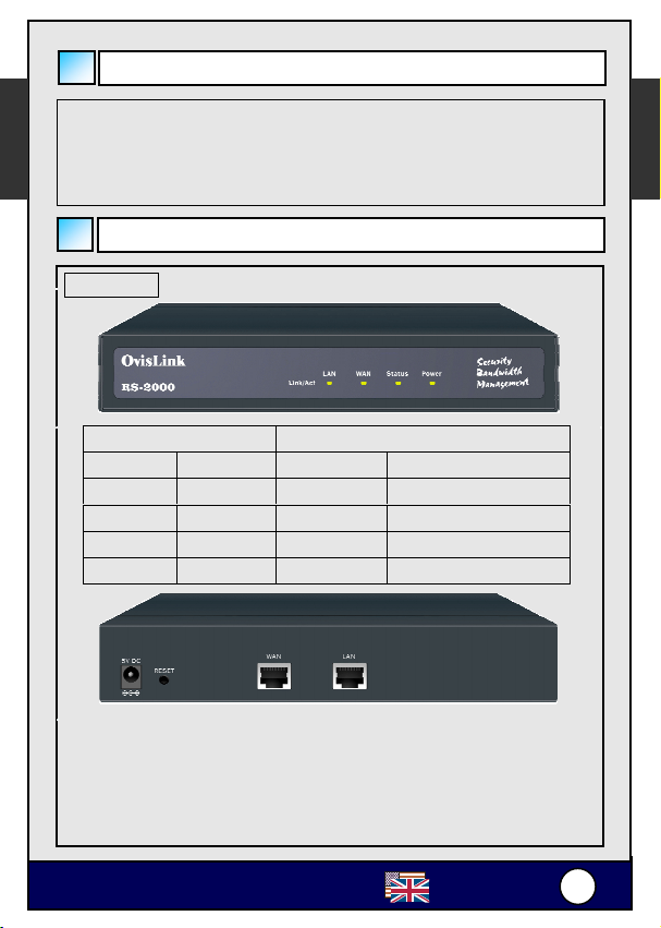
LED Indicators
RS-2000
Indicator Color ON Flashing
Power ● Green Power on -
Status ● Green Ready to use Turning on
WAN ● Green - Sending/Receiving
LAN ● Green - Sending/Receiving
LED Status
LAN Port (LAN): Use this port to connect to the LAN network of the office.
WAN Port (WAN): Use this port to connect to a router, DSL modem, or
Reset: Reset the Bandwidth Management to the original default settings.
DC Power: Connect one end of the power supply to this port, the other
Cable modem.
end to the electrical wall outlet.
OvisLink RS-2000
English
1
1
Page 3
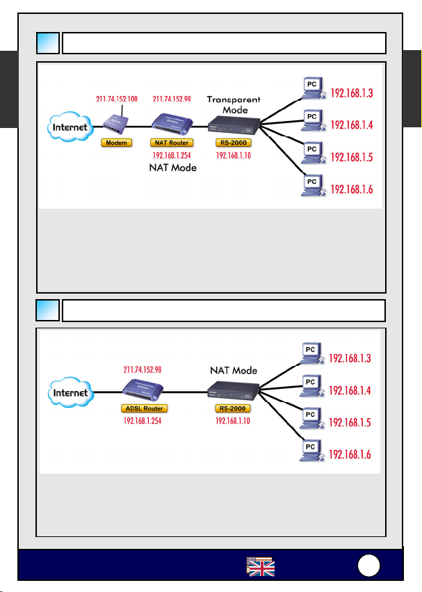
Transparent Mode Connecting Example
English
Connection Type: 10/100 Mbps Cable Connection
【LAN 1 Port】= 192.168.1.3
【LAN 2 Port】= 192.168.1.4
【LAN 3 Port】= 192.168.1.5
【LAN 4 Port】= 192.168.1.6
【WAN Port】= 192.168.1.10
English
NAT Mode Connecting Example
【LAN 1 Port】= 192.168.1.3
【LAN 2 Port】= 192.168.1.4
【LAN 3 Port】= 192.168.1.5
【LAN 4 Port】= 192.168.1.6
【WAN Port】= 61.11.11.11
OvisLink RS-2000
English
2
2
Page 4

)
English
WebUI Configuration example
STEP 1:
Connect both the Administrator’s PC and the LAN port of the Security
Bandwidth Management to a hub or switch. Make sure there is a link light
on the hub/switch for both connections. The Security Bandwidth
Management has an embedded web server used for management and
configuration. Use a web browser to display the configurations of the
Security Bandwidth Management (such as Internet Explorer 4(or above) or
Netscape 4.0(or above) with full java script support). The default IP address
of the Security Bandwidth Management is 192.168.1.1 with a subnet mask
of 255.255.255.0. Therefore, the IP address of the Administrator PC must
be in the range between 192.168.1.2– 192.168.1.254
If the company’s LAN IP Address is not subnet of 192.168.1.0, (i.e. LAN
IP Address is 172.16.0.1), then the Administrator must change his/her
PC IP address to be within the same range of the LAN subnet (i.e.
172.16.0.2
By default, the Security Bandwidth Management is shipped with its DHCP
Server function enabled. This means the client computers on the LAN
network including the Administrator PC can set their TCP/IP settings to
automatically obtain an IP address from the Security Bandwidth
Management.
The following table is a list of private IP addresses. These addresses may
not be used as a WAN IP address.
10.0.0.0 ~ 10.255.255.255
172.16.0.0 ~ 172.31.255.255
192.168.0.0 ~ 192.168.255.255
STEP 2:
Once the Administrator PC has an IP address on the same network as the
Security Bandwidth Management, open up an Internet web browser and
type in http://192.168.1.1
A pop-up screen will appear and prompt for a username and password. A
username and password is required to connect to the Security Bandwidth
Management. Enter the default login username (admin) and password
(admin) of Administrator.
. Reboot the PC if necessary.
in the address bar.
English
OvisLink RS-2000
English
3
3
Page 5

p
Setting Up in Transparent Mode
English
STEP 1:
After entering the username and password, the Security Bandwidth
Management WEB UI screen will display. Select the Interface tab on the
left menu and a sub-function list will be displayed.
◊ Select Transparent Mode.
◊ Enter required information to their corresponding fields.
System interface IP Address 192.168.1.1
NetMask 255.255.255.0
Default Gateway 192.168.1.254
DNS Server 168.95.1.1
English
Note: The above figures are only examples. Please fill in the appropriate
IP address information
STEP 2:
Click on the Policy tab from the main function menu, and then click on
Outgoing from the sub-function list.
STEP 3:
Click on New Entry button.
OvisLink RS-2000
rovided to you by the ISP.
4
English
4
Page 6

STEP 4:
When the New Entry option appears, enter the following configuration:
English
Source Address – select Inside_Any
Destination Address – select Outside_Any
Service - select ANY
Action - select Permit
Click on OK to apply the changes.
STEP 5:
The configuration is successful when the screen below is displayed. Make
sure that all the computers that are connected to the LAN port have their
Default Gateway IP Address set to the Security Bandwidth Management’s
LAN IP Address (i.e. 192.168.1.1). At this point, all the computers on the
LAN network should gain access to the Internet immediately. If a Security
Bandwidth Management filter function is required, please refer to the Policy
section in the user manual.
English
OvisLink RS-2000
English
5
5
Page 7

English
Setting Up in NAT Mode
After entering the Security Bandwidth Management WEB UI
screen, select the Interface tab on the left menu and a
sub-function list will be displayed.
Step 1: Select the NAT Mode.
Step 2: Enter the required information to their corresponding fields.
LAN Interface IP Address 192.168.1.1
NetMask 255.255.255.0
Step 3: Enter the information that your ISP provided.
WAN Interface IP Address 211.74.152.101
NetMask 255.255.255.0
Default Gateway 211.74.152.102
DNS Server 168.95.1.1
English
Step 4: Click on the Policy tab from the main function menu, and then click
on Outgoing from the sub-function list. Click on the Policy tab from
the main function menu, and then click on Incoming from the
sub-function list.
OvisLink RS-2000
English
6
6
Page 8

Step 5: Click on New Entry button.
English
Step 6: When the New Entry option appears, enter the following
configuration:
Source Address – select Inside_Any
Destination Address – select Outside_Any
Service - select ANY
Action - select Permit
Click on OK to apply the changes.
Step 7: The configuration is successful when the screen below is
displayed. Make sure that all the computers that are connected to
the LAN port have their Default Gateway IP Address set to the
Security Bandwidth Management’s LAN IP Address (i.e.
192.168.1.1). At this point, all the computers on the LAN network
should gain access to Internet immediately. If a Bandwidth
Management filter function is required, please refer to Address and
Policy sections.
English
OvisLink RS-2000
English
7
7
 Loading...