

Page 1

Contents 5
Admin 8
Setting 12
Date/Time 22
Multiple Subnet 23
Hacker Alert 34
Blaster Alert 38
Route Table 39
DHCP 43
Host Table 46
DDNS 51
Language 56
Permitted IPs 57
Logout 61
Software Update 62
Interface 63
Address 71
LAN 72
LAN Group 76
WAN 80
WAN Group 84
Page 2

Service 89
Pre-defined
Custom 91
Group 95
Schedule 99
QoS 105
Authentication 111
90
Content Filtering 141
URL Blocking 142
General Blocking 147
P2P Blocking 149
Virtual Server 155
Mapped IP 157
Virtual Server 162
Virtual Server Service 166
Policy 171
Outgoing 172
Incoming 180
VPN 187
Example 1 194
Example 2 202
Example 3 258
Example 4 266
1
Page 3

Example 5 276
Example 6 281
LOG 297
Traffic Log 298
Event Log 301
Connection Log 304
Log Backup 307
Alarm 311
Traffic Alarm 312
Event Alarm 315
Accounting Report 319
Outbound 321
inbound 329
Statistics 337
WAN Statistics 338
Policy Statistics 340
Status 343
Interface Status 344
ARP Table 345
DHCP Clients 346
2
Page 4

Setup Examples 347
Allow the LAN network to be able to access
348
the Internet
The LAN network canonly access 61.11.11.11
350
website
Outside users can access the LAN FTP
352
server through Virtual Servers.
Install a server inside the LAN network and
355
have the Internet(WAN) users access the
server through IP Mapping
Configuration of QoS inside the LAN network 358
Configuration of QoS inside the WAN network 360
3
Page 5

System
The device Bandwidth Manager administration and monitoring control is set by the system
Administrator. The System Administrator can add or modify System settings and monitoring
mode. The sub Administrators can only read System settings but not modify them. In System,
the System Administrator can:
(1) Add and change the sub Administrator’s names and passwords;
(2) Back up all Bandwidth Manager settings into local files;
(3) Set up alerts for Hackers invasion.
What is System?
“System” is the managing of settings such as the privileges of packets that pass through the
Bandwidth Manager and monitoring controls. Administrators may manage, monitor, and
configure Bandwidth Manager settings. All configurations are “read-only” for all users other
than the Administrator; those users are not able to change any settings for the Bandwidth
Manager.
The eleven sub functions under System are Admin, Setting, Date/Time, Multiple Subnet,
Hack Alert, Route Table, DHCP, Host Table, DDNS, Language, Permitted IP, SNMP,
Logout and Software Update.
Admin: has control of user access to the Bandwidth Manager. He/she can add/remove
users and change passwords.
Setting: The Administrator may use this function to backup Bandwidth Manager
configurations and export (save) them to an “Administrator” computer or anywhere on the
network; or restore a configuration file to the device; or restore the Bandwidth Manager back
to default factory settings. Under Setting, the Administrator may enable e-mail alert
notification. This will alert Administrator(s) automatically whenever the Bandwidth Manager
has experienced unauthorized access or a network hit (hacking or flooding). Once enabled,
an IP address of a SMTP(Simple Mail Transfer protocol) Server is required. Up to two e-mail
addresses can be entered for the alert notifications.
4
Page 6

Date/Time: This function enables the Bandwidth Manager to be synchronized either with an
Internet Server time or with the client computer’s clock.
Lanugage The software provides Traditional Chinese Version , Simplified Chinese
Version and English version for you to choose.
Permitted IPs Only the authorized IP address is permitted to manage the Bandwidth
Manager.
Multiple Subnet
This function allows local port to set multiple subnet works and
connect with the internet through different WAN 1 IP Addresses.
Hacker Alert When abnormal conditions occur, the will send an e-mail alert to notify the
Administrator, and also display warning messages in the Event window of Alarm.
Route Table Use this function to enable the Administrator to add static routes for the
networks when the dynamic route is not efficient enough.
DHCP Administrator can configure DHCP (Dynamic Host Configuration Protocol) settings for
the LAN (LAN) network.
Host Table The Bandwidth Manager Administrator may use the Host Table function to make
the Bandwidth Manager act as a DNS Server for the LAN. All DNS requests to a specific
Domain Name will be routed to the Bandwidth Manager’s IP address. The outside Internet
world may access the mail server of the organization easily by its domain name, providing that
the Administrator has set up Virtual Server or Mapped IP settings correctly. However, for the
users in the LAN network, their WAN DNS server will assign them a public IP address for the
mail server. So for the LAN network to access the mail server, they would have to go out to
the Internet, then come back through the Bandwidth Manager to access the mail server.
Essentially, the LAN network is accessing the mail server by a real public IP address, while
the mail server serves their request by a NAT address and not a real one.
5
Page 7

DDNS The DDNS (require DDNS Service) allows you to alias a dynamic IP address to a static
hostname, allowing your device to be more easily accessed by specific name. When this
function is enabled, the IP address in DDNS Server will be automatically updated with the new
IP address provided by ISP
Logout Administrator logs out the Bandwidth Manager. This function protects your system
while you are away.
Software Update: Administrators may visit distributor’s web site to download the latest
firmware. Administrators may update the device firmware to optimize its performance and
keep up with the latest fixes for intruding attacks.
6
Page 8
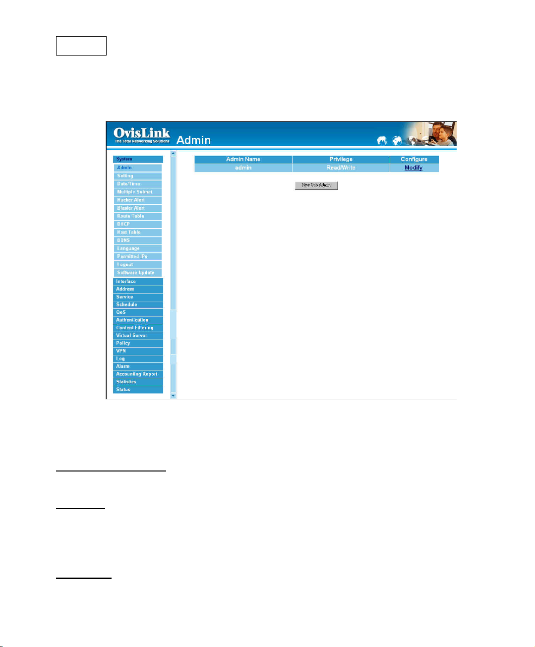
Admin
On the left hand menu, click on Setup, and then select Admin below it. The current list of
Administrator(s) shows up.
Settings of the Administration table
Administrator Name: The username of Administrators for the Bandwidth Manager. The
user admin cannot be removed.
Privilege:
The username of the main Administrator is Administrator with read / write privilege.
Sub Admins may be created by the Admin by clicking
read only privilege.
Configure:
delete a “Sub Administrator.”
The privileges of Administrators (Admin or Sub Admin)
New Sub Admin
Click Modify to change the “Sub Administrator’s” password and click Remove to
. Sub Admins have
7
Page 9
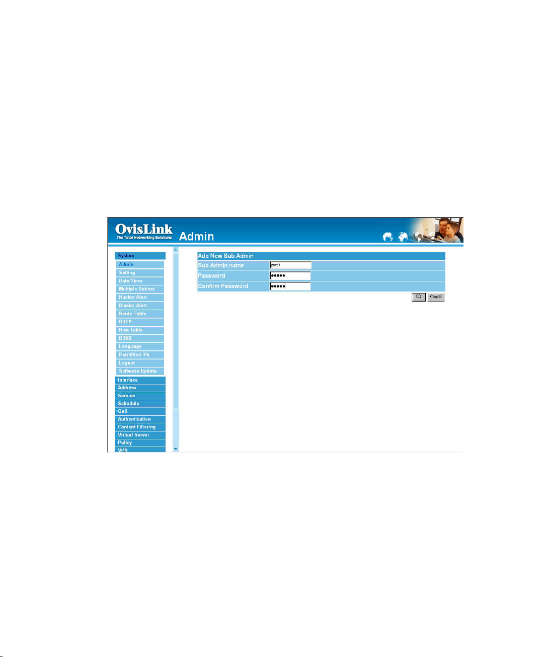
Adding a new Sub Administrator
Step 1. In the Admin window, click the New Sub Admin button to create a new Sub
Administrator.
Step 2. In the Add New Sub Administrator window:
! Sub Admin Name: enter the username of new Sub Admin.
! Password: enter a password for the new Sub Admin.
! Confirm Password: enter the password again.
Step 3. Click OK to add the user or click Cancel to cancel the addition.
8
Page 10
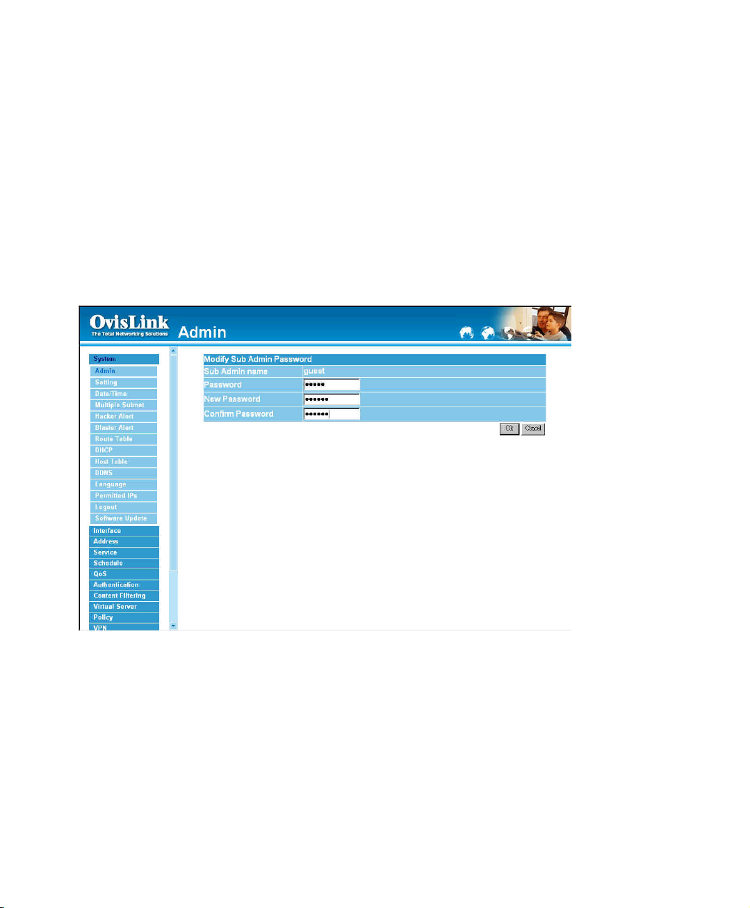
Modify the Sub-Administrator’s Password
Step 1. In the Admin window, locate the Administrator name you want to edit, and click on
Modify in the Configure field.
Step 2. The Modify Administrator Password window will appear. Enter in the required
information:
! Password: enter original password.
! New Password: enter new password
! Confirm Password: enter the new password again.
Step 3. Click OK to confirm password change or click Cancel to cancel it.
9
Page 11
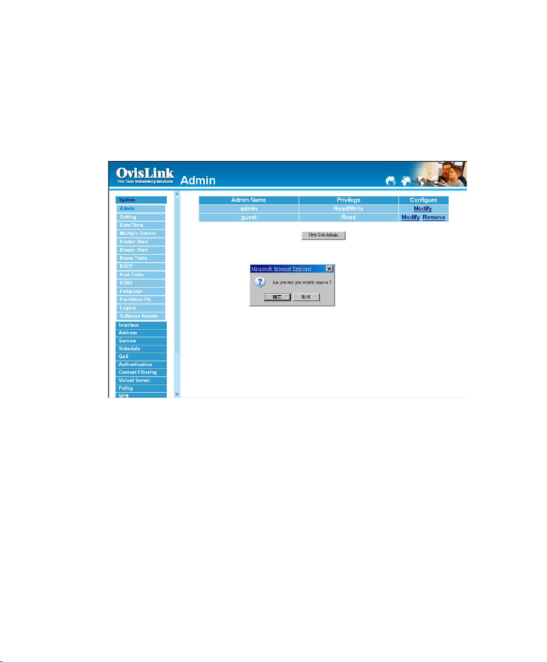
Removing a Sub Administrator
Step 1. In the Administration table, locate the Administrator name you want to edit, and click
on the Remove option in the Configure field.
Step 2. The Remove confirmation pop-up box will appear.
Step 3. Click OK to remove that Sub Admin or click Cancel to cancel.
10
Page 12

Settings
The Administrator may use this function to backup Bandwidth Manager configurations and
export (save) them to an “Administrator” computer or anywhere on the network; or restore a
configuration file to the device; or restore the Bandwidth Manager back to default factory
settings.
Link Speed / Duplex Mode:
By this function can set the transmission speed and mode of WAN Port when
connecting other device.
RIPv2:
By enable the function of Ovislink-RS2000 LAN, WAN or DMZ Port to send/receive
RIPv2 packets, and the communication between Internal Router or External Router, to
update Dynamic Routing.
11
Page 13
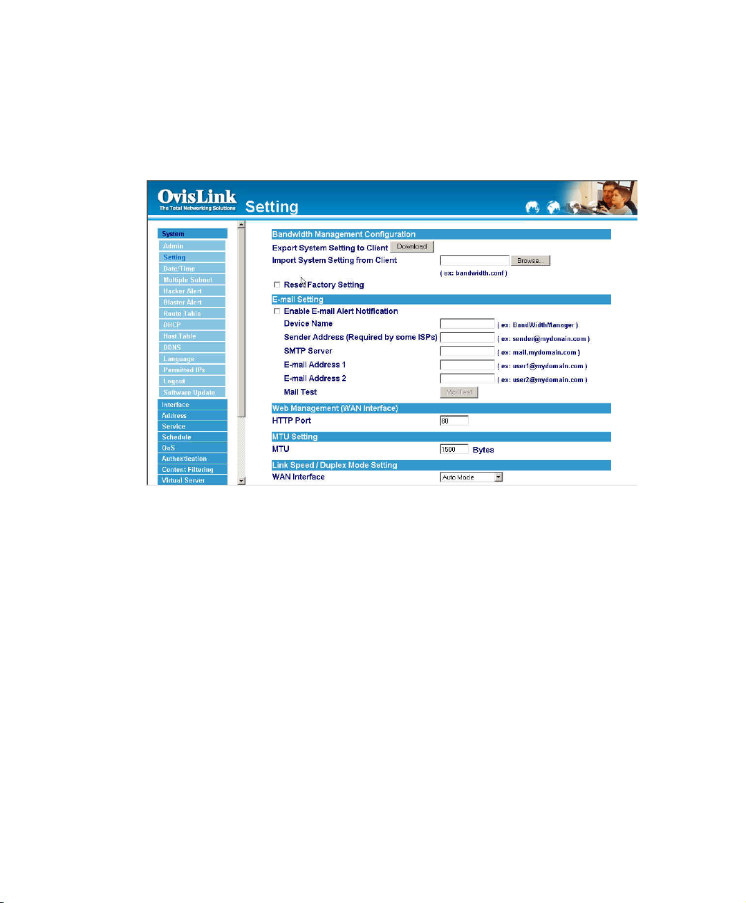
Entering the Settings window
Click Setting in the System menu to enter the Settings window. The Bandwidth Manager
Configuration settings will be shown on the screen.
12
Page 14
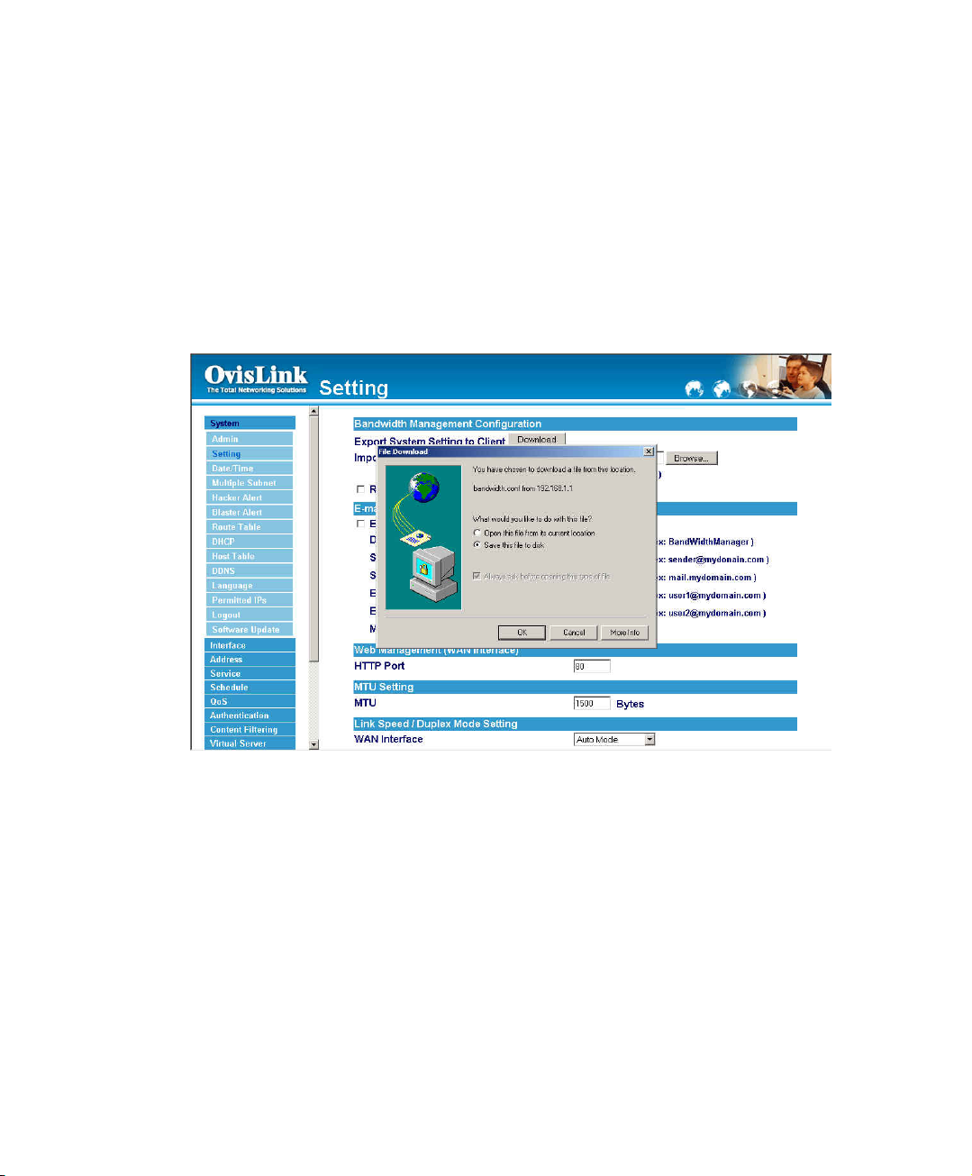
Exporting Bandwidth Manager Gateway settings
Step 1. Under Bandwidth Manager Configuration, click on the Download button next to
Export System Settings to Client.
Step 2. When the File Download pop-up window appears, choose the destination place in
which to save the exported file. The Administrator may choose to rename the file
if preferred.
13
Page 15
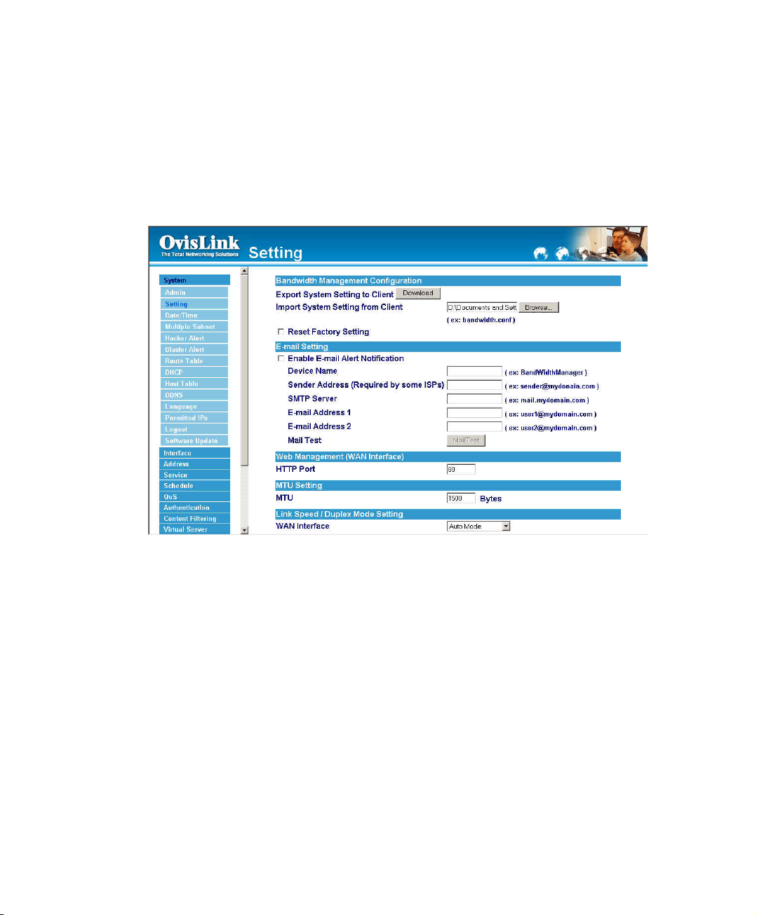
Importing Bandwidth Manager settings
Step 1. Under Bandwidth Manager Configuration, click on the Browse button next to
Import System Settings. When the Choose File pop-up window appears, select
the file to which contains the saved Bandwidth Manager Settings, then click OK.
Step 2. Click OK to import the file into the Bandwidth Manager or click Cancel to cancel
importing.
14
Page 16
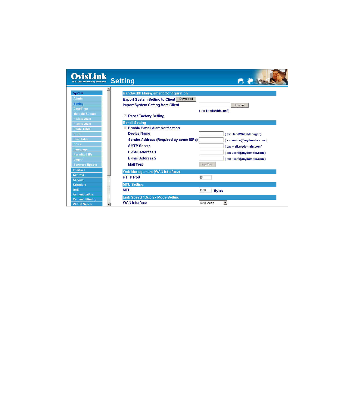
Restoring Factory Default Settings
Step 1. Select Reset Factory Settings under Bandwidth Manager Configuration.
Step 2. Click OK at the bottom-right of the screen to restore the factory settings.
15
Page 17
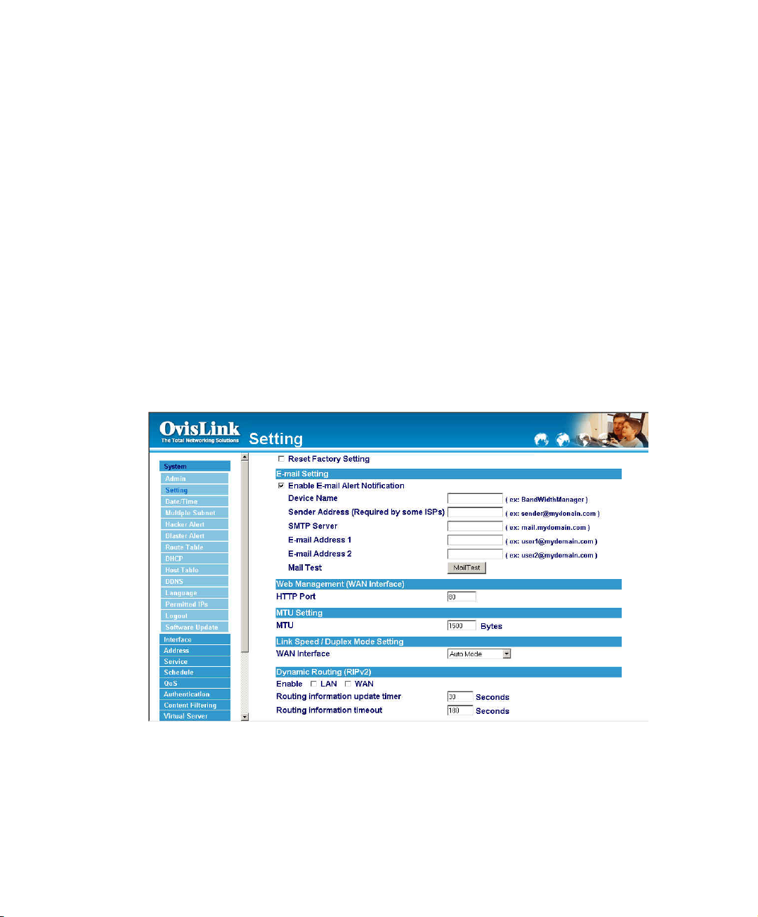
Enabling E-mail Alert Notification
Step 1. Select Enable E-mail Alert Notification under E-Mail Settings. This function will
enable the Bandwidth Manager to send e-mail alerts to the System Administrator
when the network is being attacked by hackers or when emergency conditions
occur.
Step 2. Device Name: Enter the Device Name.
Step 3. Sender Address (Required by some ISPs): Enter the Sender Address.(Some
ISPs need Required.)
Step 4. SMTP Server IP: Enter SMTP server’s IP address.
Step 5. E-Mail Address 1: Enter the first e-mail address to receive the alarm notification.
Step 6. E-Mail Address 2: Enter the second e-mail address to receive the alarm notification.
(Optional)
Step 7. Click OK on the bottom-right of the screen to enable E-mail alert notification.
16
Page 18
Web Management (WAN Interface) (Remote UI management)
The administrator can change the port number used by HTTP port anytime.
(Remote UI management)
Step 1. Set Web Management (WAN Interface). The administrator can change the port
number used by HTTP port anytime.
17
Page 19
MTU (set networking packet length)
The administrator can modify the networking packet length.
Step 1. MTU Setting. The administrator can modify the networking packet length.
18
Page 20
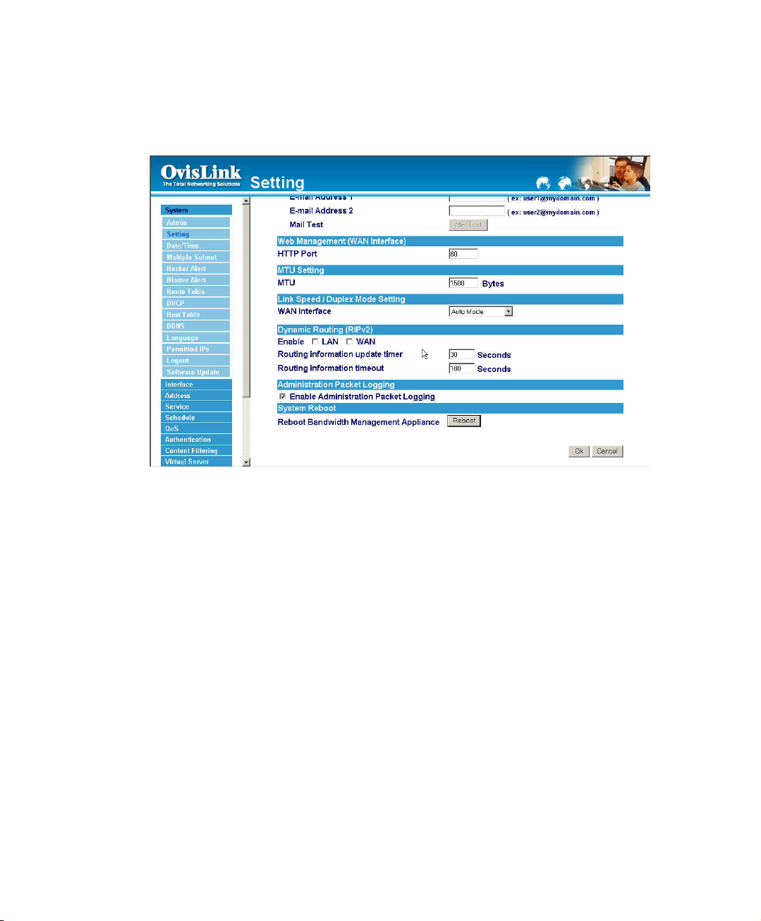
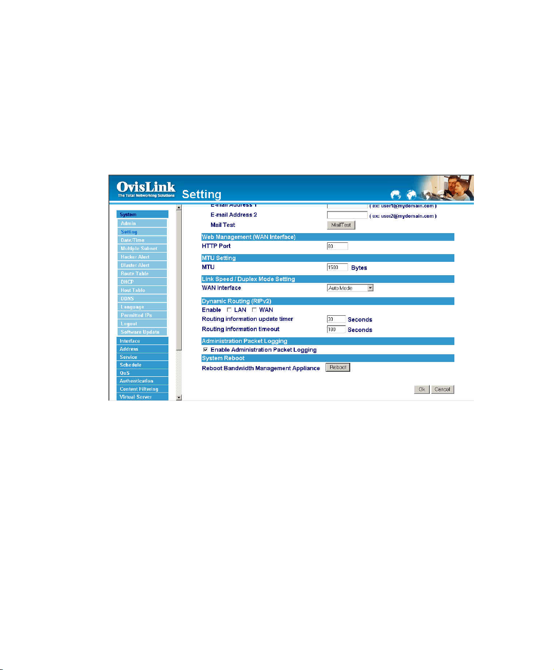
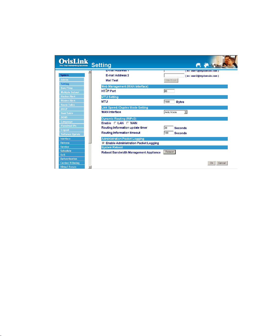
To-Bandwidth Manager Packets Log
The administrator select this option to the device’s To-Bandwidth Manager Packets Log.
Once this function is enabled, every packet to this appliance will be recorded for system
manager to trace.
19
Page 21
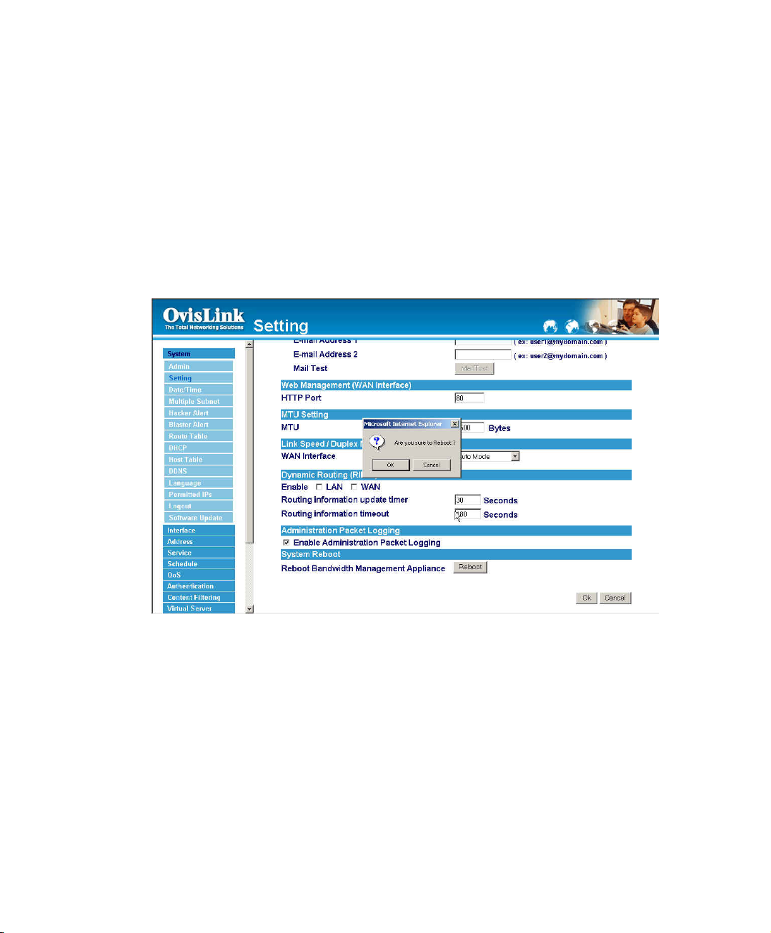
Bandwidth Manager Reboot
The administrator select this option to the device’s Bandwidth Manager Reboot. Once this
function is enabled, the Bandwidth Manager will be reboot.
Step 1. Click Setting in the Administration menu to enter the settings window.
Step 2. Reboot Bandwidth Manager:Click Reboot.
Step 3. A confirmation pop-up box will appear.
Step 4. Follow the confirmation pop-up box, click OK to restart Bandwidth Manager or
click Cancel to discard changes.
20
Page 22
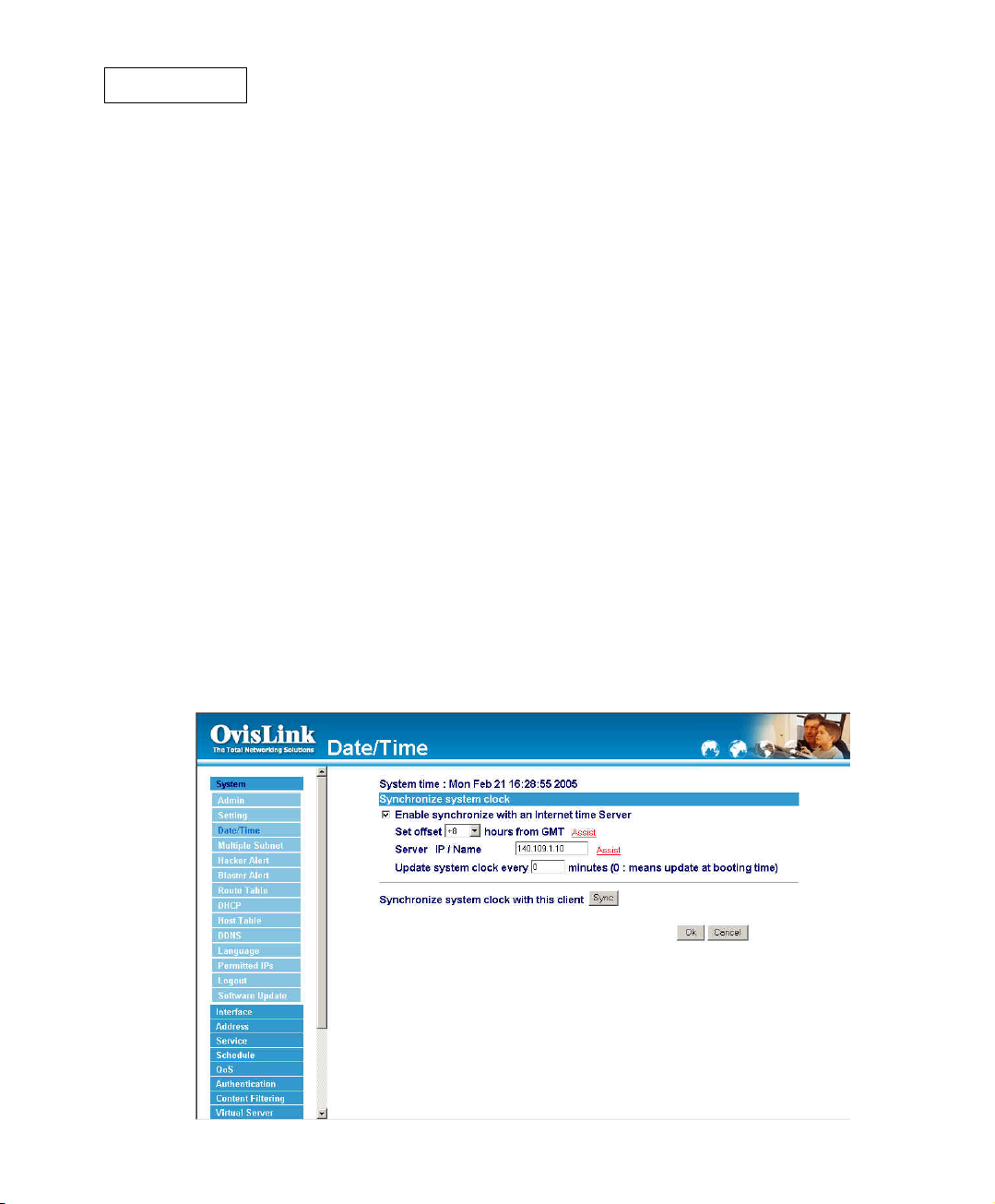
Date/Time
Synchronizing the Bandwidth Manager with the System Clock
The administrator can configure the Bandwidth Manager.s date and time by either syncing
to an Internet Network Time Server (NTP) or by syncing to your computer.s clock.
Follow these steps to sync to an Internet Time Server
Step 1. Enable synchronization by checking the box.
Step 2. Click the down arrow to select the offset time from GMT.
Step 3. Enter the Server IP Address or Server name with which you want to
synchronize.
Step 4. Update system clock every 5 minutes You can set the interval
time to synchronize with outside servers. If you set it to 0, it means
the device will not synchronize automatically.
Follow this step to sync to your computer’s clock.
Step 1. Click on the Sync button.
Click the OK button below to apply the setting or click Cancel to discard
changes.
21
Page 23

Multiple Subnet
NAT mode
Multiple Subnet allows local port to set multiple subnet works and connect with the internet
through different WAN IP Addresses.
For instance:The lease line of a company applies several real IP Addresses 168.85.88.0/24,and
the company is divided into R&D department, service, sales department, procurement
department, accounting department, the company can distinguish each department by
different subnet works for the purpose of convenient management. The settings are as the
following:
1.R&D department subnet work:192.168.1.11/24(LAN) "# 168.85.88.253(WAN 1)
2. Service department subnet work: 192.168.2.11/24(LAN) "# 168.85.88.252(WAN 1)
3.Sales department subnet work: 192.168.3.11/24(LAN) "# 168.85.88.251(WAN 1)
4. Procurement department subnet work
192.168.4.11/24(LAN) "# 168.85.88.250(WAN 1)
5. Accounting department subnet work
192.168.5.11/24(LAN) "# 168.85.88.249(WAN 1)
The first department(R&D department) was set while setting interface IP, the other four
ones have to be added in Multiple Subnet,after completing the settings, each deparm ent
use the different WAN IP Address to connect to the internet. The settings of each
department are as the following
Service IP Address:192.168.2.1
Subnet Mask:255.255.255.0
Default Gateway:192.168.2.11
The other departments are also set by groups, this is the function of Multiple Subnet.
22
Page 24
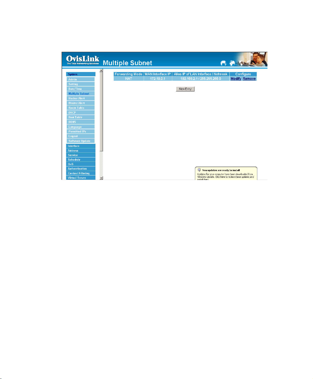
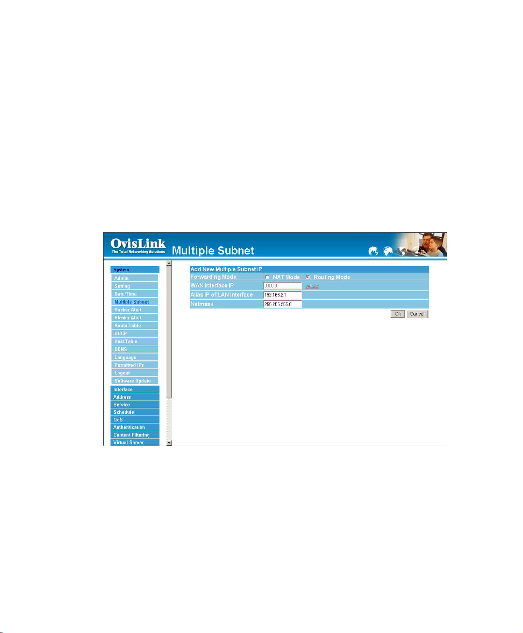
Multiple Subnet settings
Click Multiple Subnet in the System menu to enter Multiple Subnet window.
Multiple Subnet
! Forwarding Mode: Display forwarding Mode. NAT mode / Routing Mode.
! WAN Interface IP:Display WAN Port IP Address.
! Alias IP of Int. Interface / Netmask: Local port IP Address and subnet
Mask.
! Modify:Modify the settings of Multiple Subnet. Click Modify to modify the
parameters of Multiple Subnet or click Delete to delete settings.
23
Page 25
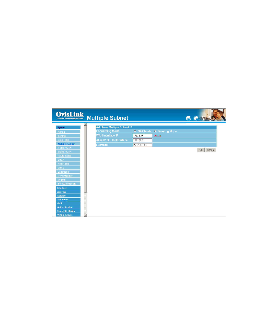
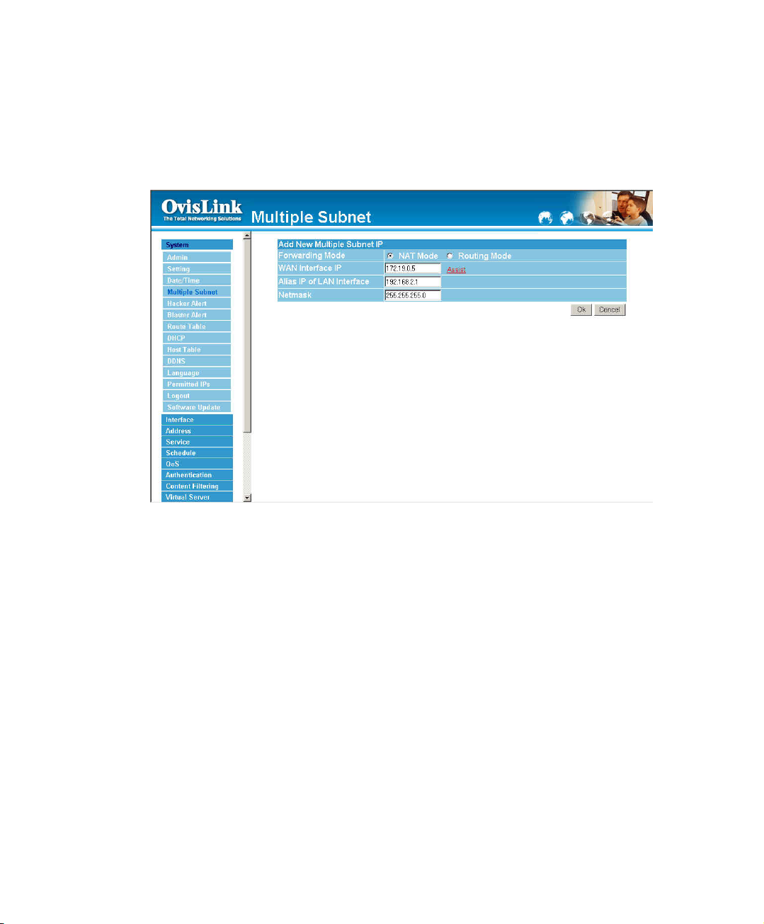
Add a Multiple Subnet NAT Mode.
Step 1. Click the Add button below to add Multiple Subnet.
Step 2. Enter the IP Address in the website name column of the new window.
Forwarding Mode Click the NAT button below to setting.
Alias IP of LAN Interface: Enter Local port IP Address.
Netmask:Enter Local port subnet Mask.
WAN Interface IP: Add WAN IP Address.
Step 3. Click OK to add Multiple Subnet or click Cancel to discard changes.
24
Page 26
Modify a Multiple Subnet
Step 1. Find the IP Address you want to modify and click Modify
Step 2. Enter the new IP Address in Modify Multiple Subnet window.
Step 3. Click the OK button below to change the setting or click Cancel to discard changes.
25
Page 27
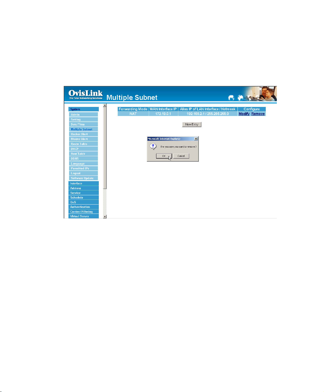
Removing a Multiple Subnet
Step 1.Find the IP Address you want to delete and click Delete.
Step 2.A confirmaion pop-up box will appear, click OK to delete the setting or click Cancel to
discard changes.
26
Page 28
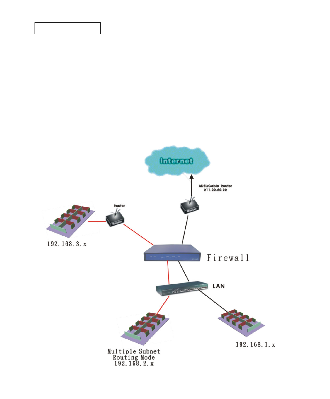
Routing Mode
Multiple Subnet allows local port to set Multiple Subnet Routing Mode works and connect
with the internet through different WAN IP Addresses.
For example, the leased line of a company applies several real IP Addresses 192.168.2.0/24 and
the company is divided into R&D, Customer Service, Sales, Procurement, and Accounting
Department. The company can distinguish each department by different subnet works for
the purpose of convenient management.
The settings are as the following:
27
Page 29
Step 1. Click System Configuration on the left side menu bar, then click Multiple
Subnet below it. Enter Multiple Subnet window.
Step 2. The definition of Multiple Subnet :
! Forwarding Mode:Display Forwarding Mode which is NAT Mode or Routing
Mode.
! WAN Interface IP: Display WAN Port IP Address.
! Alias IP of Int. Interface / Subnet Mask: Local port IP Address and subnet
Mask.
! Modify:Modify the settings of Multiple Subnet. Click Modify to modify the
parameters of Multiple Subnet or click Delete to delete settings.
28
Page 30
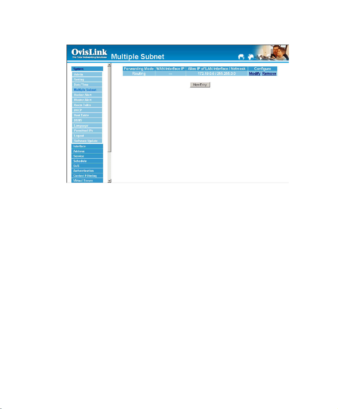
Adding a Multiple Subnet Routing Mode
Step 1. Click the Add button below to add Multiple Subnet.
Step 2. Enter the IP Address in Add Multiple Subnet window.
Forwarding Mode : Click the Routing button below to setting
WAN Interface IP : Add WAN IP.
Alias IP of LAN Interface: Enter Local port IP Address.
Netmask:Enter Local port subnet Mask.
Step 3. Click OK to add Multiple Subnet or click Cancel to discard changes.
29
Page 31

Step 4: Adding a new Incoming Policy. In the incoming window, click the New Entry button.
30
Page 32

Modify a Multiple Subnet Routing Mode
Step 1. Find the IP Address you want to modify in Multiple Subnet menu, then click Modify
button, on the right side of the service providers, click OK.
Step 2. Enter the new IP Address in Modify Multiple Subnet window.
Step 3. Click the OK button below to change the setting or click Cancel to discard changes.
31
Page 33

Removing a Multiple Subnet Routing Mode
Step 1. Find the IP Address you want to delete in Multiple Subnet menu, then click Delete
button, on the right side of the service providers, click OK.
Step 2. A confirmation pop-up box will appear, click OK to delete the setting or click Cancel to
discard changes.
32
Page 34

Hacker Alert
The Administrator can enable the device’s auto detect functions in this section. When
abnormal conditions occur, the Bandwidth Manager will send an e-mail alert to notify the
Administrator, and also display warning messages in the Event window of Alarm.
Auto Detect functions
! Detect SYN Attack: Select this option to detect TCP SYN attacks that
hackers send to server computers continuously to block or cut down all the
connections of the servers. These attacks will prevent valid users from
connecting to the servers.
【SYN Flood Threshold( Total) Pkts/Sec】: The System Administrator can enter
the maximum number of SYN packets per second that is allow to enter the
network/Bandwidth Manager.
【SYN Flood Threshold( Per Source IP) Pkts/Sec】: The System Administrator
can enter the maximum number of SYN packets per second from attacking
source IP Address that is allow to enter the network/Bandwidth Manager.
33
Page 35

【SYN Flood Threshold Blocking Time ( Per Source IP) Seconds】: The
System Administrator can enter the blocking time when the number of SYN
packets per second from attacking source IP Address that is allow to enter
the network/Bandwidth Manager exceed the maximum number (define as
above). After blocking for certain seconds, the device will start to calculate
the max number of SYN packets per second from attacking source IP
Address, if the max number still exceed the define value, it will block the
attacking IP Address continuously.
! Detect ICMP Attack: Select this option to detect ICMP flood attacks. When
hackers continuously send PING packets to all the machines of the LAN
networks or to the Bandwidth Manager via broadcasting, your network is
experiencing an ICMP flood attack.
【ICMP Flood Threshold( Total) Pkts/Sec】: The System Administrator can
enter the maximum number of ICMP packets per second that is allow to
enter the network/Bandwidth Manager.
【ICMP Flood Threshold( Per Source IP) Pkts/Sec】: The System Administrator
can enter the maximum number of ICMP packets per second from attacking
source IP Address that is allow to enter the network / Bandwidth Manager.
【ICMP Flood Threshold Blocking Time ( Per Source IP) Seconds】: The
System Administrator can enter the blocking time when the number of ICMP
packets per second from attacking source IP Address that is allow to enter
the network / Bandwidth Manager exceed the maximum number (define as
above). After blocking for certain seconds, the device will start to calculate
the max number of ICMP packets per second from attacking source IP
Address, if the max number still exceed the define value, it will block the
attacking IP Address continuously.
! Detect UDP Attack: The same as ICMP Flood.
【UDP Flood Threshold( Total) Pkts/Sec】: The System Administrator can enter
the maximum number of UDP packets per second that is allow to enter the
network/Bandwidth Manager.
34
Page 36

【UDP Flood Threshold( Per Source IP) Pkts/Sec】: The System Administrator
can enter the maximum number of UDP packets per second from attacking
source IP Address that is allow to enter the network/Bandwidth Manager.
【UDP Flood Threshold Blocking Time ( Per Source IP) Seconds】: The
System Administrator can enter the blocking time when the number of UDP
packets per second from attacking source IP Address that is allow to enter
the network/Bandwidth Manager exceed the maximum number (define as
above). After blocking for certain seconds, the device will start to calculate
the max number of UDP packets per second from attacking source IP
Address, if the max number still exceed the define value, it will block the
attacking IP Address continuously.
! Detect Ping of Death Attack: Select this option to detect the attacks of tremendous
trash data in PING packets that hackers send to cause System malfunction This
attack can cause network speed to slow down, or even make it necessary to restart
the computer to get a normal operation.
! Detect IP Spoofing Attack: Select this option to detect spoof attacks. Hackers
disguise themselves as trusted users of the network in Spoof attacks. They use a
fake identity to try to pass through the Bandwidth Manager System and invade the
network.
! Detect Port Scan Attack: Select this option to detect the port scans hackers use to
continuously scan networks on the Internet to detect computers and vulnerable ports
that are opened by those computers.
! Detect Tear Drop Attack: Select this option to detect tear drop attacks. These are
packets that are segmented to small packets with negative length. Some Systems
treat the negative value as a very large number, and copy enormous data into the
System to cause System damage, such as a shut down or a restart.
! Filter IP Source Route Option: Each IP packet can carry an optional field that
specifies the replying address that can be different from the source address
specified in packet’s header. Hackers can use this address field on disguised
packets to invade LAN networks and send LAN networks’ data back to them.
35
Page 37

! Detect Land Attack: Some Systems may shut down when receiving packets with
the same source and destination addresses, the same source port and destination
port, and when SYN on the TCP header is marked. Enable this function to detect
such abnormal packets.
After enabling the needed detect functions, click OK to activate the changes.
36
Page 38

Blaster Alert
The Administrator can enable the device’s auto detect functions in this section. When
abnormal conditions occur, the Bandwidth Manager will send an e-mail blaster / SNMP Trap
alert to notify the Administrator, and also display warning messages in the Event window of
Alarm.
Auto Detect functions
! Enable Blaster Blocking : Select this option to detect Blaster attacks that
Blaster send to server computers continuously to block or cut down all the
connections of the servers. These attacks will prevent valid users from
connecting to the servers.
【Blocking Time Seconds】: The System Administrator can enter the blocking
time when the number of Blaster packets per second from attacking source
IP Address that is allow to enter the network/Bandwidth Manager exceed the
maximum number (define as above). After blocking for certain seconds, the
device will start to calculate the max number of Blaster packets per second
from attacking source IP Address, if the max number still exceed the define
value, it will block the attacking IP Address continuously.
! Enable E-Mail Alert Notification:This function will enable the Blaster Blocking to send e-mail alerts
to the System Administrator when the network is being attacked by Blaster.
37
Page 39

Route Table
In this section, the Administrator can add static routes for the networks.
Entering the Route Table screen
Click System on the left side menu bar, then click Route Table below it. The Route Table
window appears, in which current route settings are shown.
Route Table functions
! Interface: Destination network , LAN or WAN networks.
! Destination IP: IP address of destination network.
! NetMask: Netmask of destination network.
! Gateway: Gateway IP address for connecting to destination network.
! Configure: Change settings in the route table.
38
Page 40

Adding a new Static Route
Step 1. In the Route Table window, click the New Entry button.
Step 2. In the Add New Static Route window, enter new static route information.
Step 3. In the Interface field’s pull-down menu, choose the network to connect (LAN, WAN).
Step 4. Click OK to add the new static route or click Cancel to cancel.
39
Page 41

Modifying a Static Route:
Step 1. In the Route Table menu, find the route to edit and click the corresponding Modify
option in the Configure field.
Step 2. In the Modify Static Route window, modify the necessary routing addresses.
Step 3. Click OK to apply changes or click Cancel to cancel it.
40
Page 42

Removing a Static Route
Step 1. In the Route Table window, find the route to remove and click the corresponding
Remove option in the Configure field.
Step 2. In the Remove confirmation pop-up box, click OK to confirm removing or click
Cancel to cancel it.
41
Page 43

DHCP
In the section, the Administrator can configure DHCP (Dynamic Host Configuration Protocol)
settings for the LAN (LAN) network.
Entering the DHCP window
Step 1. Click System on the left hand side menu bar, then click DHCP below it. The DHCP
window appears in which current DHCP settings are shown on the screen.
DHCP Address functions
Enable DHCP Support:Enable /Disable DCHP Support
! Domain Name:Enter the Domain Name of DHCP
Automatically Get DNS:Automatically detect DNS Server.
! DNS Server 1 : Enter the distributed IP address of DNS Server1.
! DNS Server 2 : Enter the distributed IP address of DNS Server2.
! WINS Server 1 : Enter the distributed IP address of WINS Server1.
! WINS Server 2 : Enter the distributed IP address of WINS Server2.
42
Page 44

LAN Interface :
! Client IP Address Range 1: Enter the starting and the ending IP address
dynamically assigning to DHCP clients.
! Client IP Address Range 2: Enter the starting and the ending IP address
dynamically assigning to DHCP clients. (Optional)
! Leased Time: Enter the leased time for DHCP.
43
Page 45

Enabling DHCP Support
Step 1. In the Dynamic IP Address window, click Enable DHCP Support.
Step 2.
Enable DHCP Support:Enable /Disable DCHP Support
! Domain Name:Enter the Domain Name of DHCP
Automatically Get DNS:Automatically detect DNS Server.
! DNS Server 1 : Enter the distributed IP address of DNS Server1.
! DNS Server 2 : Enter the distributed IP address of DNS Server2.
! WINS Server 1 : Enter the distributed IP address of WINS Server1.
! WINS Server 2 : Enter the distributed IP address of WINS Server2.
LAN Interface :
! Client IP Address Range 1: Enter the starting and the ending IP address dynamically
assigning to DHCP clients.
! Client IP Address Range 2: Enter the starting and the ending IP address dynamically
assigning to DHCP clients. (Optional)
! Leased Time: Enter the leased time for DHCP.
Step 3. Click OK to enable DHCP support.
44
Page 46

Host Table
The Bandwidth Manager’s Administrator may use the Host Table function to make the
Bandwidth Manager act as a DNS Server for the LAN. All DNS requests to a specific
Domain Name will be routed to the Bandwidth Manager’s IP address. The outside Internet
world may access the mail server of the organization easily by its domain name, providing that
the Administrator has set up Virtual Server or Mapped IP settings correctly. However, for the
users in the LAN network, their WAN DNS server will assign them a public IP address for the
mail server. So for the LAN network to access the mail server (mail.MH2000.com), they
would have to go out to the Internet, then come back through the Bandwidth Manager to
access the mail server. Essentially, the LAN network is accessing the mail server by a real
public IP address, while the mail server serves their request by a NAT address and not a real
one.
This odd situation occurs when there are servers in the DMZ network and they are binded to
real IP addresses. To avoid this, set up Host Table so all the LAN network computers will
use the Bandwidth Manager as a DNS server, which acts as the Host Table.
If you want to use the Host Table function of the device, the end user’s main DNS
server IP address should be the same IP Address as the device.
45
Page 47

Entering the Host Table window
Click on System in the menu bar, then click on Host Table below it. The Host Table window
will appear.
Below is the information needed for setting up the Host Table:
• Domain Name: The domain name of the server
• Virtual IP Address: The virtual IP address respective to Host Table
• Configure: modify or remove each Host Table policy
46
Page 48

Adding a new Host Table
Step 1: Click on the New Entry button and the Add New Host Table window will appear.
Step 2: Fill in the appropriate settings for the domain name and virtual IP address.
Step 3: Click OK to save the policy or Cancel to cancel.
47
Page 49

Modifying a Host Table
Step 1: In the Host Table window, find the policy to be modified and click the corresponding
Modify option in the Configure field.
Step 2: Make the necessary changes needed.
Step 3: Click OK to save changes or click on Cancel to cancel modifications.
48
Page 50

Removing a Host Table
Step 1: In the Host Table window, find the policy to be removed and click the corresponding
Remove option in the Configure field.
Step 2: A confirmation pop-up box will appear, click OK to remove the Host Table or click
Cancel.
49
Page 51

DDNS
The DDNS (require DDNS Service) allows you to alias a dynamic IP address to a static
hostname, allowing your device to be more easily accessed by specific name. When this
function is enabled, the IP address in DDNS Server will be automatically updated with the
new IP address provided by ISP.
Click DDNS in the System menu to enter DDNS window.
1. The nouns in DDNS window:
! Update Status【
Unidentified error】
! Domain name:Enter the password provided by ISP.
! WAN IP Address:IP Address of the WAN port.
! Modify:Modify DDNS settings. Click Modify to change the DNS parameters;
click Delete to delete the settings.
2. How to use DDNS:
The Bandwidth Manager provides 3 service providers, users have to regidter first to use
this function. For the usage regulations, see the providers’ websites.
How to register
click Add button,on the right side of the service providers, click Register, the service
peroviders’ website will appear, please refer to the website for the way of registration.
:First, Click DDNS in the System menu to enter DDNS window, then
Connecting; Update succeed; Update fail;
50
Page 52

How to register:Firstly, Click DDNS in the System menu to enter DDNS window, then click
Add button,on the right side of the service providers, click Register, the service providers’
website will appear, please refer to the website for the way of registration.
51
Page 53

DDNS settings
Step 1: Click Add button.
Step 2: Click the information in the column of the new window.
! Service providers:Select service providers.
! Register:to the service providers’ website.
! WAN IP Address:IP Address of the WAN port.
! $ automatically fill in the WAN IP:Check to automatically fill in the WAN
IP.。
! User Name:Enter the registered user name.
! Password:Enter the password provided by ISP(Internet Service Provider).
! Domain name:Your host domain name provided by ISP.
Step 4: Click OK to add DDNS or click Cancel to discard changes.
52
Page 54

Modify a DDNS
Step 1: Find the item you want to change and click Modify.
Step 2: Enter the new information in the Modify DDNS window.
Step 3: Click OK to change the settings or click Cancel to discard changes.
53
Page 55

Removing a DDNS
Step 1: Find the item you want to change and click Delete.
Step 2: A confirmation pop-up box will appear, click OK to delete the settings or click Cancel
to discard changes.
54
Page 56

Language
The administrator can configure the Bandwidth Manager Select the Language version.
Step 1. Select the Language version (English Version/Traditional Chinese Version or
Simplified Chinese Version).
Step 2. Click 【OK】to set the Language version or click Cancel to discard changes.
55
Page 57

Permitted IPs
Only the authorized IP address is permitted to manage the Bandwidth Manager.
56
Page 58

Add a Permitted IP Address
Step 1. Click New Entry button.
Step 2. In IP Address field, enter the LAN IP address or WAN IP address.
! IP address:Enter the LAN IP address or WAN IP address.
! Netmask:Enter the netmask of LAN/WAN.
! Ping:Select this to allow the WAN network to ping the IP Address of the
Firewall.
! WebUI:Check this item, Web User can use HTTP to connect to the Setting
window of Bandwidth Manager.
Step 3. Click OK to add Permitted IP or click Cancel to discard changes.
57
Page 59

Modify a Permitted IP Address
Step 1. In the table of Permitted IPs, highlight the IP you want to modify, and then click
Modify.
Step 2. In Modify Permitted IP, enter new IP address.
Step 3. Click OK to modify or click Cancel to discard changes.
58
Page 60

Remove a Permitted IP addresses
Step 1. In the table of Permitted IPs, highlight the IP you want to remove, and then click
Remove.
Step 2. In Remove Permitted IP, enter new IP address.
Step 3. In the confirm window, click OK to remove or click Cancel to discard changes.
59
Page 61

Logout
Select this option to the device’s Logout the Bandwidth Manager. This function protects your
system while you are away.
Step 1. Click Logout the Bandwidth Manager.
Step 2. Click OK to logout or click Cancel to discard the change.
60
Page 62

Software Update
Under Software Update, the admin may update the device’s software with a newer software.
61
Page 63

Interface
In this section, the Administrator can set up the IP addresses for the office network. The
Administrator may configure the IP addresses of the LAN network, the WAN network. The
netmask and gateway IP addresses are also configured in this section.
62
Page 64

LAN
Entering the Interface menu
Click on Interface in the left menu bar. Then click on LAN below it. The current settings of
the interface addresses will appear on the screen.
63
Page 65

Configuring the Interface Settings
LAN Interface
Using the LAN Interface, the Administrator sets up the LAN network. The LAN network will
use a private IP scheme. The private IP network will not be routable on the Internet.
IP Address: The private IP address of the Bandwidth Manager’s LAN network is the IP
address of the LAN port of the device. The default IP address is 192.168.1.1.
If the new LAN IP Address is not 192.168.1.1, the Administrator needs to set the IP Address
on the computer to be on the same subnet as the Bandwidth Manager and restart the System
to make the new IP address effective. For example, if the Bandwidth Manager’s new LAN IP
Address is 172.16.0.1, then enter the new LAN IP Address 172.16.0.1 in the URL field of
browser to connect to Bandwidth Manager.
NetMask: This is the netmask of the LAN network. The default netmask of the device is
255.255.255.0.
Ping: Select this to allow the LAN network to ping the IP Address of the Bandwidth Manager.
If set to enable, the device will respond to ping packets from the LAN network.
WebUI: Select this to allow the device WEBUI to be accessed from the LAN network.
64
Page 66

WAN
Entering the Interface menu
Click on Interface in the left menu bar. Then click on WAN below it. The current
settings of the interface addresses will appear on the screen.
65
Page 67

WAN Interface
Using the WAN Interface, the Administrator sets up the WAN network. These IP Addresses
are real public IP Addresses, and are routable on the Internet.
For PPPoE (ADSL User):
username and password in order to connect, such as ADSL users.
Current Status: Displays the current line status of the PPPoE connection.
IP Address: Displays the IP Address of the PPPoE connection
Username: Enter the PPPoE username provided by the ISP.
Password: Enter the PPPoE password provided by the ISP.
IP Address provided by ISP:
Dynamic: Select this if the IP address is automatically assigned by the ISP.
Fixed: Select this if you were given a static IP address. Enter the IP address that is
given to you by your ISP.
Max. Upstream/Downstream Bandwidth: The bandwidth provided by ISP.
Service-On-Demand:
Auto Disconnect: The PPPoE connection will automatically disconnect after a length
of idle time (no activities). Enter in the amount of idle minutes before disconnection.
Enter ‘0’ if you do not want the PPPoE connection to disconnect at all.
Ping: Select this to allow the WAN network to ping the IP Address of the Bandwidth
Manager. This will allow people from the Internet to be able to ping the Bandwidth
Manager. If set to enable, the device will respond to echo request packets from the
WAN network.
This option is for PPPoE users who are required to enter a
WebUI: Select this to allow the device WEBUI to be accessed from the WAN network.
This will allow the WebUI to be configured from a user on the Internet. Keep in mind
that the device always requires a username and password to enter the WebUI.
66
Page 68

67
Page 69

For Dynamic IP Address (Cable Modem User): This option is for users who are
automatically assigned an IP address by their ISP, such as cable modem users.
The following fields apply:
IP Address: The dynamic IP address obtained by the Bandwidth Manager from the
ISP will be displayed here. This is the IP address of the WAN port of the device.
MAC Address: This is the MAC Address of the device.
Hostname: This will be the name assign to the device. Some cable modem ISP
assign a specific hostname in order to connect to their network. Please enter the
hostname here. If not required by your ISP, you do not have to enter a hostname.
Ping: Select this to allow the WAN network to ping the IP Address of the Bandwidth
Manager. This will allow people from the Internet to be able to ping the Bandwidth
Manager. If set to enable, the device will respond to echo request packets from the
WAN network.
Max. Upstream/Downstream Bandwidth: The bandwidth provided by ISP.
WebUI: Select this to allow the device WEBUI to be accessed from the WAN network.
This will allow the WebUI to be configured from a user on the Internet. Keep in mind
that the device always requires a username and password to enter the WebUI.
68
Page 70

For Static IP Address: This option is for users who are assigned a static IP Address from
their ISP.Your ISP will provide all the information needed for this section such as IP Address,
Netmask, Gateway, and DNS.Use this option also if you have more than one public IP
Address assigned to you.
IP Address: Enter the static IP address assigned to you by your ISP. This will be
the public IP address of the WAN port of the device.
Netmask: This will be the Netmask of the WAN network. (i.e. 255.255.255.0)
Default Gateway: This will be the Gateway IP address.
Domain Name Server (DNS): This is the IP Address of the DNS server.
Max. Upstream/Downstream Bandwidth: The bandwidth provided by ISP.
Ping: Select this to allow the WAN network to ping the IP Address of the Bandwidth
Manager. This will allow people from the Internet to be able to ping the Bandwidth
Manager. If set to enable, the device will respond to echo request packets from the
WAN network.
WebUI: Select this to allow the device WEBUI to be accessed from the WAN network.
This will allow the WebUI to be configured from a user on the Internet. Keep in mind
that the device always requires a username and password to enter the WebUI.
69
Page 71

Address
The Bandwidth Manager allows the Administrator to set Interface addresses of the LAN
network, LAN network group, WAN network, WAN network group.
What is the Address Table?
An IP address in the Address Table can be an address of a computer or a sub network. The
Administrator can assign an easily recognized name to an IP address. Based on the network
it belongs to, an IP address can be an LAN IP address, WAN IP address. If the Administrator
needs to create a control policy for packets of different IP addresses, he can first add a new
group in the LAN Network Group or the WAN Network Group and assign those IP addresses
into the newly created group. Using group addresses can greatly simplify the process of
building control policies.
With easily recognized names of IP addresses and names of address groups shown in the
address table, the Administrator can use these names as the source address or destination
address of control policies. The address table should be built before creating control policies,
so that the Administrator can pick the names of correct IP addresses from the address table
when setting up control policies.
70
Page 72

LAN
Entering the LAN window
Step 1. Click LAN under the Address menu to enter the LAN window. The current setting
information such as the name of the LAN network, IP and Netmask addresses will
show on the screen.
71
Page 73

Adding a new LAN Address
Step 1. In the LAN window, click the New Entry button.
Step 2. In the Add New Address window, enter the settings of a new LAN network address.
Step 3. Click OK to add the specified LAN network or click Cancel to cancel the changes.
72
Page 74

Modifying an LAN Address
Step 1. In the LAN window, locate the name of the network to be modified. Click the
Modify option in its corresponding Configure field. The Modify Address window
appears on the screen immediately.
Step 2. In the Modify Address window, fill in the new addresses.
Step 3. Click OK to save changes or click Cancel to discard changes.
73
Page 75

Removing an LAN Address
Step 1. In the LAN window, locate the name of the network to be removed. Click the
Remove option in its corresponding Configure field.
Step 2. In the Remove confirmation pop-up box, click OK to remove the address or click
Cancel to discard changes.
74
Page 76

LAN Group
Entering the LAN Group window
The LAN Addresses may be combined together to become a group.
Click LAN Group under the Address menu to enter the LAN Group window. The current
setting information for the LAN network group appears on the screen.
75
Page 77

Adding an LAN Group
Step 1. In the LAN Group window, click the New Entry button to enter the Add New
Address Group window.
Step 2.
Step 3. Add members: Select names to be added in Available Address list, and click the
Step 4. Remove members: Select names to be removed in the Selected Address list, and
Step 5. Click OK to add the new group or click Cancel to discard changes.
In the Add New Address Group window:
! Available Address: list the names of all the members of the LAN network.
! Selected Address: list the names to be assigned to the new group.
! Name: enter the name of the new group in the open field.
Add>> button to add them to the Selected Address list.
click the <<Remove button to remove these members from Selected Address list.
76
Page 78

Modifying an LAN Group
Step 1. In the LAN Group window, locate the network group desired to be modified and click
its corresponding Modify option in the Configure field.
Step 2. A window displaying the information of the selected group appears:
! Available Address: list names of all members of the LAN network.
! Selected Address: list names of members which have been assigned to this group.
Step 3. Add members: Select names in Available Address list, and click the Add>> button
to add them to the Selected Address list.
Step 4. Remove members: Select names in the Selected Address list, and click the
<<Remove button to remove these members from the Selected Address list.
Step 5. Click OK to save changes or click Cancel to discard changes.
77
Page 79

Removing an LAN Group
Step 1. In the LAN Group window, locate the group to be removed and click its
corresponding Remove option in the Configure field.
Step 2. In the Remove confirmation pop-up box, click OK to remove the group or click
Cancel to discard changes.
78
Page 80

WAN
Entering the WAN window
Click WAN under the Address menu to enter the WAN window. The current setting
information, such as the name of the WAN network, IP and Netmask addresses will show on
the screen.
79
Page 81

Adding a new WAN Address
Step 1. In the WAN window, click the New Entry button.
Step 2. In the Add New Address window, enter the settings for a new WAN network
address.
Step 3. Click OK to add the specified WAN network or click Cancel to discard changes.
80
Page 82

Modifying an WAN Address
Step 1. In the WAN table, locate the name of the network to be modified and click the
Modify option in its corresponding Configure field.
Step 2. The Modify Address window will appear on the screen immediately. In the Modify
Address window, fill in new addresses.
Step 3. Click OK to save changes or click Cancel to discard changes.
81
Page 83

Removing an WAN Address
Step 1. In the WAN table, locate the name of the network to be removed and click the
Remove option in its corresponding Configure field.
Step 2. In the Remove confirmation pop-up box, click OK to remove the address or click
Cancel to discard changes.
82
Page 84

WAN Group
Entering the WAN Group window
Click the WAN Group under the Address menu bar to enter the WAN window. The current
settings for the WAN network group(s) will appear on the screen.
83
Page 85

Adding an WAN Group
Step 1. In the WAN Group window, click the New Entry button and the Add New Address
Group window will appear.
Step 2. In the Add New Address Group window the following fields will appear:
! Name: enter the name of the new group.
! Available Address: List the names of all the members of the WAN network.
! Selected Address: List the names to assign to the new group.
Step 3. Add members: Select the names to be added in the Available Address list, and
click the Add>> button to add them to the Selected Address list.
Step 4. Remove members: Select the names to be removed in the Selected Address list,
and click the <<Remove button to remove them from the Selected Address list.
Step 5. Click OK to add the new group or click Cancel to discard changes.
84
Page 86

Modify an WAN Group
Step 1. In the WAN Group window, locate the network group to be modified and click its
corresponding Modify button in the Configure field.
Step 2. A window displaying the information of the selected group appears:
! Available Address: list the names of all the members of the WAN network.
! Selected Address: list the names of the members that have been assigned to this
group.
Step 3. Add members: Select the names to be added in the Available Address list, and
click the Add>> button to add them to the Selected Address list.
Step 4. Remove members: Select the names to be removed in the Selected Address list,
and click the <<Remove button to remove them from the Selected Address list.
Step 5. Click OK to save changes or click Cancel to discard changes.
85
Page 87

Removing an WAN Group
Step 1. In the WAN Group window, locate the group to be removed and click its
corresponding Modify option in the Configure field.
Step 2. In the Remove confirmation pop-up box, click OK to remove the group or click
Cancel to discard changes.
86
Page 88

87
Page 89

Service
In this section, network services are defined and new network services can be added.
There are three sub menus under Service which are: Pre-defined, Custom, and Group.
The Administrator can simply follow the instructions below to define the protocols and port
numbers for network communication applications. Users then can connect to servers and
other computers through these available network services.
What is Service?
TCP and UDP protocols support varieties of services, and each service consists of a TCP
Port or UDP port number, such as TELNET(23), SMTP(21), POP3(110),etc. The 10/100M 2
WAN/ LAN Bandwidth Manager defines two services: pre-defined service and custom service.
The common-use services like TCP and UDP are defined in the pre-defined service and
cannot be modified or removed. In the custom menu, users can define other TCP port and
UDP port numbers that are not in the pre-defined menu according to their needs. When
defining custom services, the client port ranges from 1024 to 65535 and the server port
ranges from 0 to 1023.
How do I use Service?
The Administrator can add new service group names in the Group option under Service
menu, and assign desired services into that new group. Using service group the
Administrator can simplify the processes of setting up control policies. For example, there are
10 different computers that want to access 5 different services on a server, such as HTTP,
FTP, SMTP, POP3, and TELNET. Without the help of service groups, the Administrator needs
to set up 50 (10x5) control policies, but by applying all 5 services to a single group name in
the service field, it takes only one control policy to achieve the same effect as the 50 control
policies.
88
Page 90

Pre-defined
Entering a Pre-defined window
Click Service on the menu bar on the left side of the window. Click Pre-defined under it. A
window will appear with a list of services and their associated IP addresses. This list cannot
be modified.
89
Page 91

Custom
Entering the Custom window
Click Service on the menu bar on the left side of the window. Click Custom under it. A
window will appear with a table showing all services currently defined by the Administrator.
90
Page 92

Adding a new Service
Step 1. In the Custom window, click the New Entry button and a new service table appears.
Step 2. In the new service table:
! New Service Name: This will be the name referencing the new service.
! Protocol: Enter the network protocol type to be used, such as TCP, UDP, or Other
(please enter the number for the protocol type).
! Client Port: enter the range of port number of new clients.
! Server Port: enter the range of port number of new servers.
The client port ranges from 1024 to 65535 and the server port ranges from 0 to 1023.
Step 3. Click OK to add new services, or click Cancel to cancel.
91
Page 93

Modifying Custom Services
Step 1. In the Custom table, locate the name of the service to be modified. Click its
corresponding Modify option in the Configure field.
Step 2. A table showing the current settings of the selected service appears on the screen
Step 3. Enter the new values.
Step 4. Click OK to accept editing; or click Cancel.
92
Page 94

Removing Custom Services
Step 1. In the Custom window, locate the service to be removed. Click its corresponding
Remove option in the Configure field.
Step 2. In the Remove confirmation pop-up box, click OK to remove the selected service or
click Cancel to cancel action.
93
Page 95

Group
Accessing the Group window
Click Service in the menu bar on the left hand side of the window. Click Group under it. A
window will appear with a table displaying current service group settings set by the
Administrator.
94
Page 96

Adding Service Groups
Step 1. In the Group window, click the New Entry button.
In the Add Service Group window, the following fields will appear:
! Available Services: list all the available services.
! Selected Services: list services to be assigned to the new group.
Step 2. Enter the new group name in the group Name field. This will be the name
referencing the created group.
Step 4. To add new services: Select the services desired to be added in the Available
Services list and then click the Add>> button to add them to the group.
Step 5. To remove services: Select services desired to be removed in the Available
Services, and then click the <<Remove button to remove them from the group.
Step 6. Click OK to add the new group.
95
Page 97

Modifying Service Groups
Step 1. In the Group window, locate the service group to be edited. Click its
corresponding Modify option in the Configure field.
Step 2. In the Mod (modify) group window the following fields are displayed::
! Available Services: lists all the available services.
! Selected Services: list services that have been assigned to the selected group.
Step 3. Add new services: Select services in the Available Services list, and then click the
Add>> button to add them to the group.
Step 4. Remove services: Select services to be removed in the Selected Services list, and
then click the <<Remove button to remove theses services from the group.
Step 5. Click OK to save editing changes.
96
Page 98

Removing Service Groups
Step 1. In the Group window, locate the service group to be removed and click its
corresponding Remove option in the Configure field.
Step 2. In the Remove confirmation pop-up box, click OK to remove the selected service
group or click Cancel to cancel removing.
97
Page 99

Schedule
The Bandwidth Manager allows the Administrator to configure a schedule for policies to take
affect. By creating a schedule, the Administrator is allowing the Bandwidth Manager policies
to be used at those designated times only. Any activities outside of the scheduled time slot
will not follow the Bandwidth Manager policies therefore will likely not be permitted to pass
through the Bandwidth Manager. The Administrator can configure the start time and stop
time, as well as creating 2 different time periods in a day. For example, an organization may
only want the Bandwidth Manager to allow the LAN network users to access the Internet
during work hours. Therefore, the Administrator may create a schedule to allow the
Bandwidth Manager to work Monday-Friday, 8AM-5PM only. During the non-work hours, the
Bandwidth Manager will not allow Internet access.
98
Page 100

Accessing the Schedule window
Click on Schedule on the menu bar and the schedule window will appear displaying the
active schedules.
The following items are displayed in this window:
Name: the name assigned to the schedule
Comment: a short comment describing the schedule
Configure: modify or remove
99
 Loading...