

Page 1

RS-1200
Dual WAN Security Gateway
User’s Manual
Page 2

Contents
System
Chapter 1
Chapter 2
Administration ……………………………………………. 5
Admin ……………………………………………………... 7
Permitted IPs …………………………………………….. 9
Logout ………………………………………………….…. 10
Software Update …………………………………………. 11
Configure ………………………………………………….. 12
Setting ………………………………………………….…. 17
Date/Time …………………………………………………. 22
Multiple Subnet … ……………………………...… … … … 23
RouteTable ………………………………………………... 26
DHCP ………………………………………………………. 30
Interface
Chapter 3
DDNS ……………………………………………...… … … .. 32
Host Table ……………………………………………….… 34
Language ……………………………………………..……... 35
Interface …………………………………………………... 36
LAN ………………………………….……………………. 41
WAN ………………………………….…………………… 42
DMZ …………………………….………………………… 50
2
Page 3

Policy Object
Chapter 4
Chapter 5
Chapter 6
Chapter 7
Chapter 8
Chapter 9
Address ……………………………………………………. 52
Example ………………………………….………………… 54
Service ………………………………………………….…. 62
Custom ………………………………….………………… 65
Group … ……………………………….………………….. 69
Schedule …………………………………………………. 72
QoS ………………………………………………….……. 75
Example ………………………………….………………. 78
Authentication …………………………………………… 81
Example ………………………………….………………. 86
Content Filtering ………………………………………… 90
URL ………………………………….…………………… 94
Script ……………………………….……………………. 97
P2P ………………………….…………………………… 99
IM …………………………….…………………………… 101
Download …………………………….…………………... 103
Chapter 10 Virtual Server………………………………………………... 105
Example ……………………………….………………….. 109
Chapter 11 VPN ………………………………………………………. 124
Example…………………………………………………….. 132
Policy
Chapter 12 Policy……………………………………………….……….. 156
Example ………………………………….………………. 162
3
Page 4

Anti-Attack
Chapter13 Alert Setting ………………………………………………. 180
Internal Alert ……………………………………………… 185
Chapter14 Atack Alarm … … … ………………………………………. 189
Monitor
Internal Alarm …………………………………………….. 191
External Alarm ……………………………………………… 192
Chapter15 LOG ……………………………………………….……….. 194
Chapter16 Accounting
Traffic Log ……………………….………………………… 196
Event Log ……………………….………………………… 201
Connection Log … …………………….…………………. 204
Log Backup … … … ……………….……………………… 207
210
Report …………………….………………….
Outbound ……………………….………………………… 212
Inbound ………………………….………………………… 217
Chapter17 Statistics …………………………………………….…….. 223
WAN ……………………….………………………………. 225
Policy ……………………….……………………………… 227
Chapter18 Status …………………………………………….………… 229
Interface ……………………….………………………….. 230
Authentication ……………………….…………………… 232
ARP Table ……………………….………………………... 233
DHCP Clients ……………………….……………………. 234
4
Page 5

Chapter 1
Administration
“System” is the managing of settings such as the privileges
of packets that pass through the AirLive RS-1200 and monitoring
controls.
The System Administrators can manage, monitor, and configure
AirLive RS-1200 settings. But all configurations are “read-only”
for all users other than the System Administrator; those users
are not able to change any setting of the AirLive RS-1200.
5
Page 6

Define the required fields of Administrator
Administrator Name:
The username of Administrators and Sub Administrator for the RS-1200. The
admin user name cannot be removed; and the sub-admin user can be removed or
configure.
The default Account: admin; Password: admin
Privilege:
The privileges of Administrators (Admin or Sub Admin). The username of the main
Administrator is Administrator with reading / writing privilege. Administrator also
can change the system setting, log system status, and to increase or delete
sub-administrator. Sub-Admin may be created by the Admin by clicking
Admin
system setting value.
. Sub Admin have only read and monitor privilege and cannot change any
New Sub
Configure:
Click Modify to change the “Sub-Administrator’s” password or click Remove to
delete a “Sub Administrator.”
6
Page 7
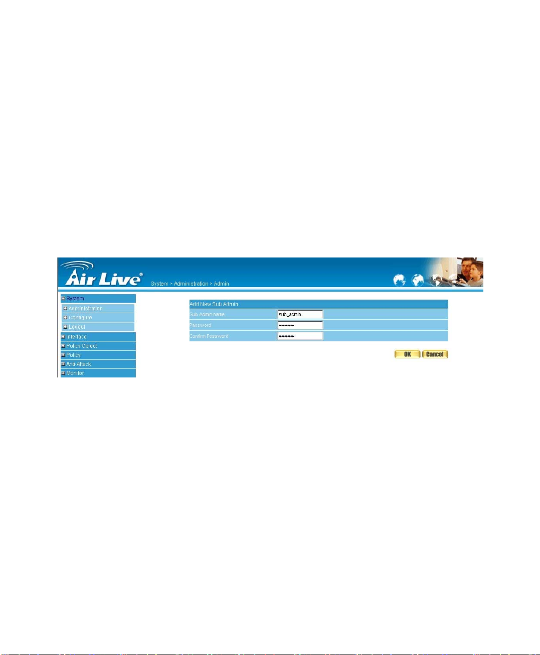
Adding a new Sub Administrator
STEP 1﹒In the Admin WebUI, click the New Sub Admin button to create a
new Sub Administrator.
STEP 2﹒In the Add New Sub Administrator WebUI (Figure 1-1) and enter the
following setting:
Sub Admin Name: sub_admin
Password: 12345
Confirm Password: 12345
STEP 3﹒Click OK to add the user or click Cancel to cancel it.
Figure1-1 Add New Sub Admin
7
Page 8
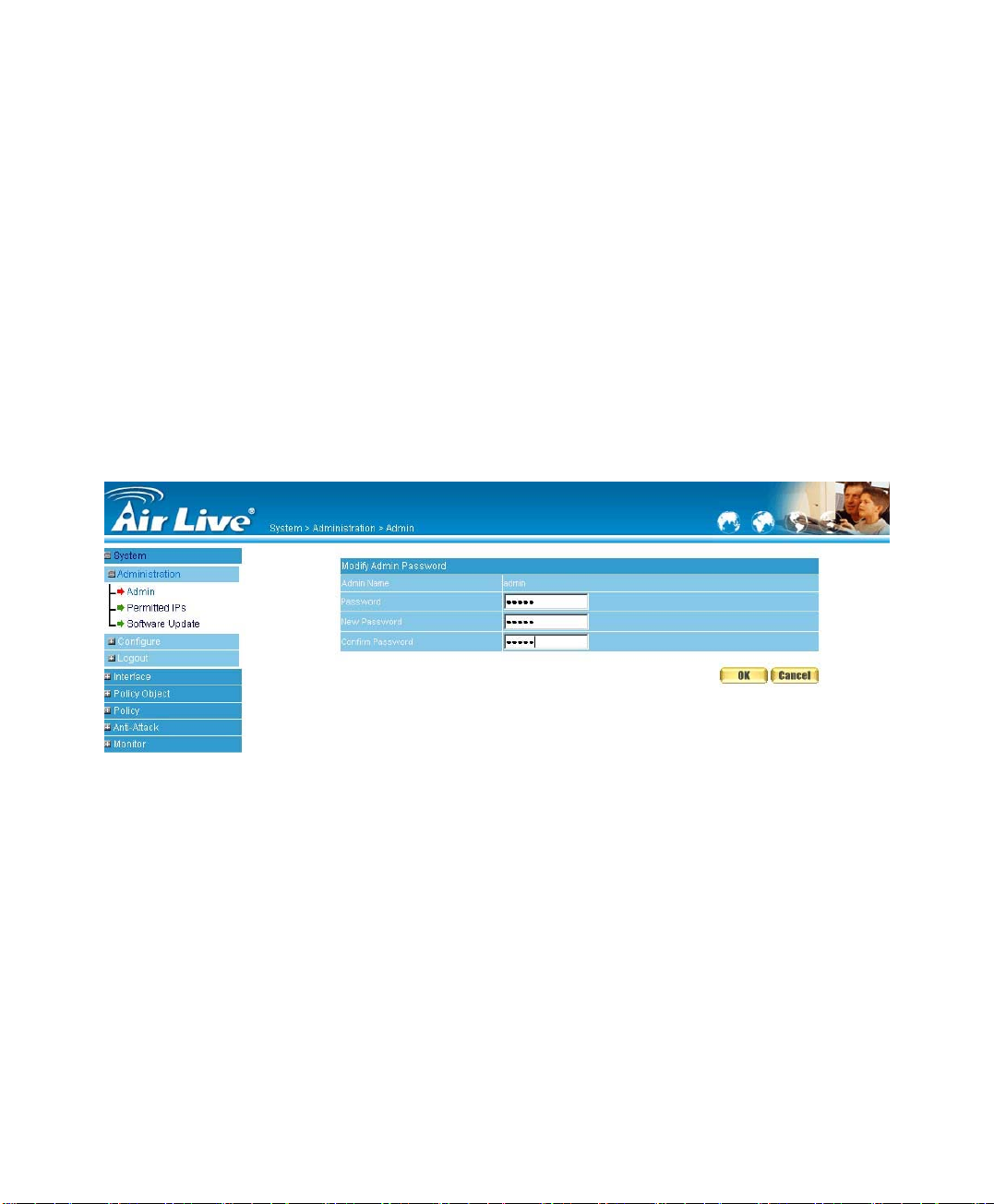
Modify the Administrator’s Password
STEP 1﹒In the Admin WebUI, locate the Administrator name you want to edit, and
click on Modify in the Configure field.
STEP 2﹒The Modify Administrator Password WebUI will appear. Enter the
following information:
Password: admin
New Password: 52364
Confirm Password: 52364 (Figure1-2)
STEP 3﹒Click OK to confirm password change.
Figure1-2 Modify Admin Password
8
Page 9
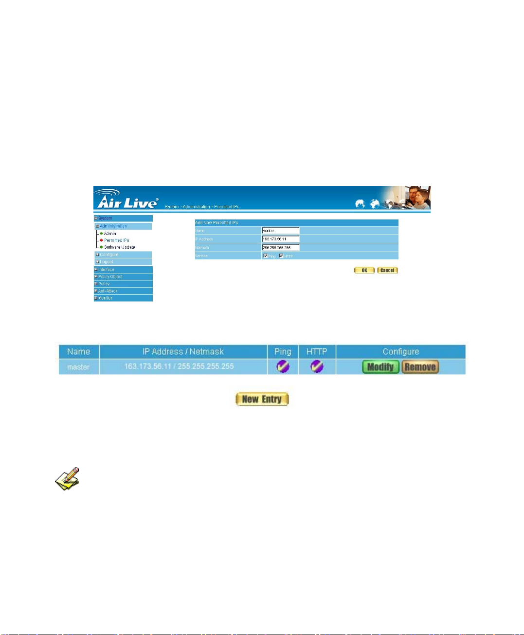
Add Permitted IPs
STEP 1﹒Add the following setting in Permitted IPs of Administration: (Figure1-3)
Name: Enter master
IP Address: Enter 163.173.56.11
Netmask: Enter 255.255.255.255
Service: Select Ping and HTTP
Click OK
Complete add new permitted IPs (Figure1-4)
Figure1-3 Setting Permitted IPs WebUI
Figure1-4 Complete Add New Permitted IPs
To make Permitted IPs be effective, it must cancel the Ping and WebUI selection
in the WebUI of RS-1200 that Administrator enter. (LAN, WAN, or DMZ Interface)
Before canceling the WebUI selection of Interface, must set up the Permitted IPs first,
otherwise, it would cause the situation of cannot enter WebUI by appointed Interface.
9
Page 10
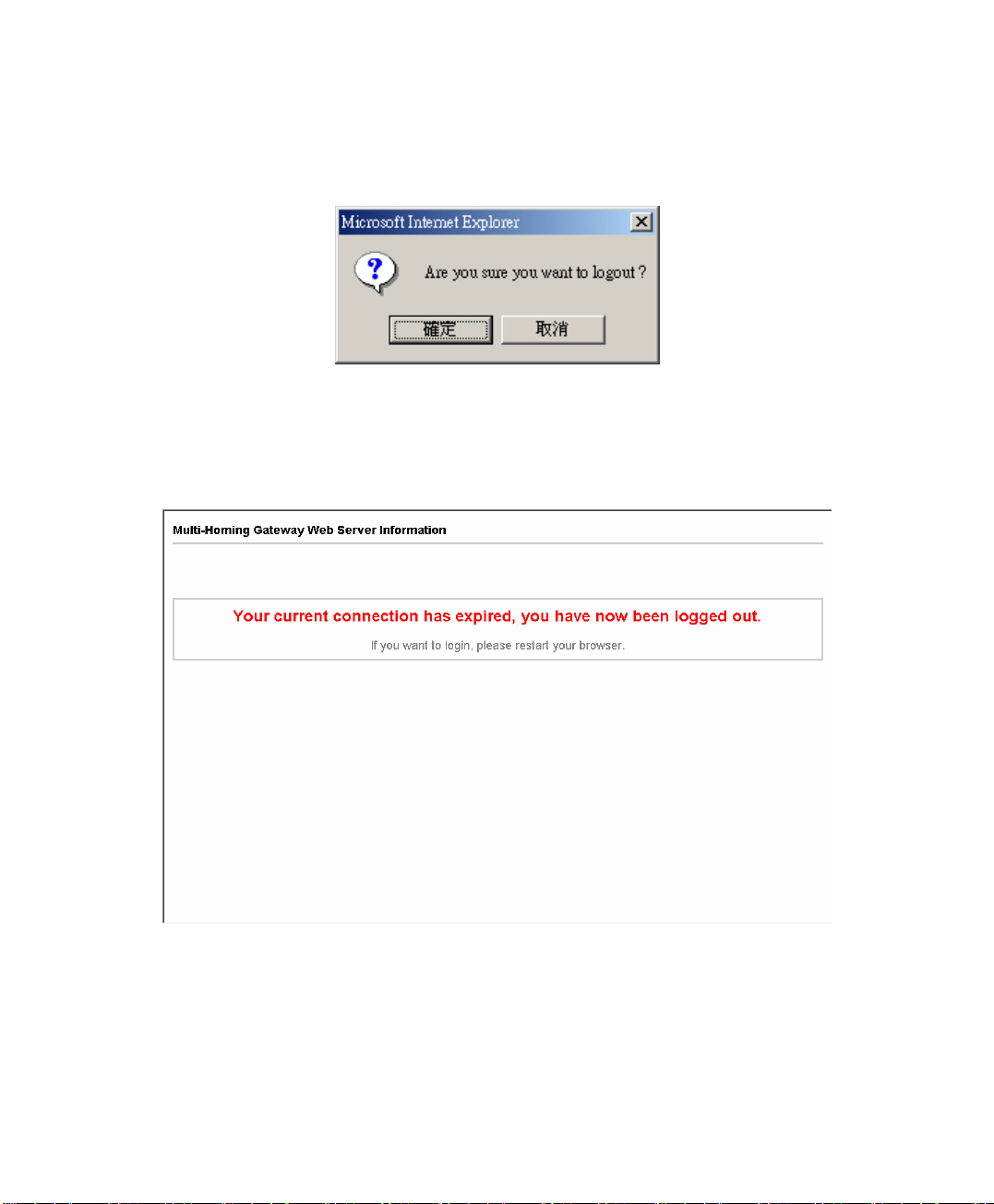
Logout
STEP 1﹒Click Logout in System to protect the system while Administrator are away.
(Figure1-5)
Figure1-5 Confirm Logout WebUI
STEP 2﹒Click OK and the logout message will appear in WebUI. (Figure1-6)
Figure1-6 Logout WebUI Message
10
Page 11
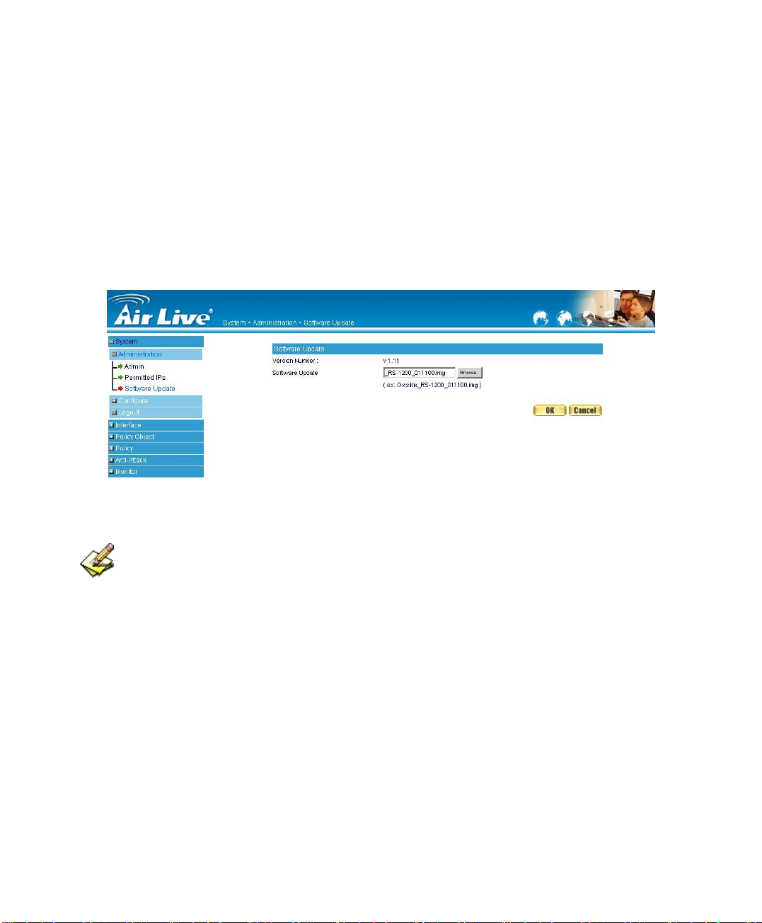
Software Update
STEP 1﹒Select Software Update in SystemÆAdministraion,
and follow the steps below:
To obtain the version number from Version Number and obt ain the latest
version from Internet. And save the latest version in the hardware of the
PC, which manage the RS-1200
Click Browse and choose the latest software version file.
Click OK and the system will update automatically. (Figure1-7)
Figure1-7 Software Update
It takes 3 minutes to update software. The system will reboot after update. During
the updating time, please don’t turn off the PC or leave the WebUI. It may cause some
unexpected mistakes. (Strong suggests updating the software from LAN to avoid
unexpected mistakes.)
11
Page 12

Chapter 2
Configure
The Configure is according to the basic setting of the AirLive RS-1200.
In this chapter the definition is Setting, Date/Time, Multiple Subnet, Route
Table, DHCP, Dynamic DNS, Hosts Table, and Language settings.
Define the required fields of Settings
AirLive RS-1200 Configuration:
The Administrator can import or export the system settings. Click OK to import the
file into the RS-1200 or click Cancel to cancel importing. You also can revive to
default value here.
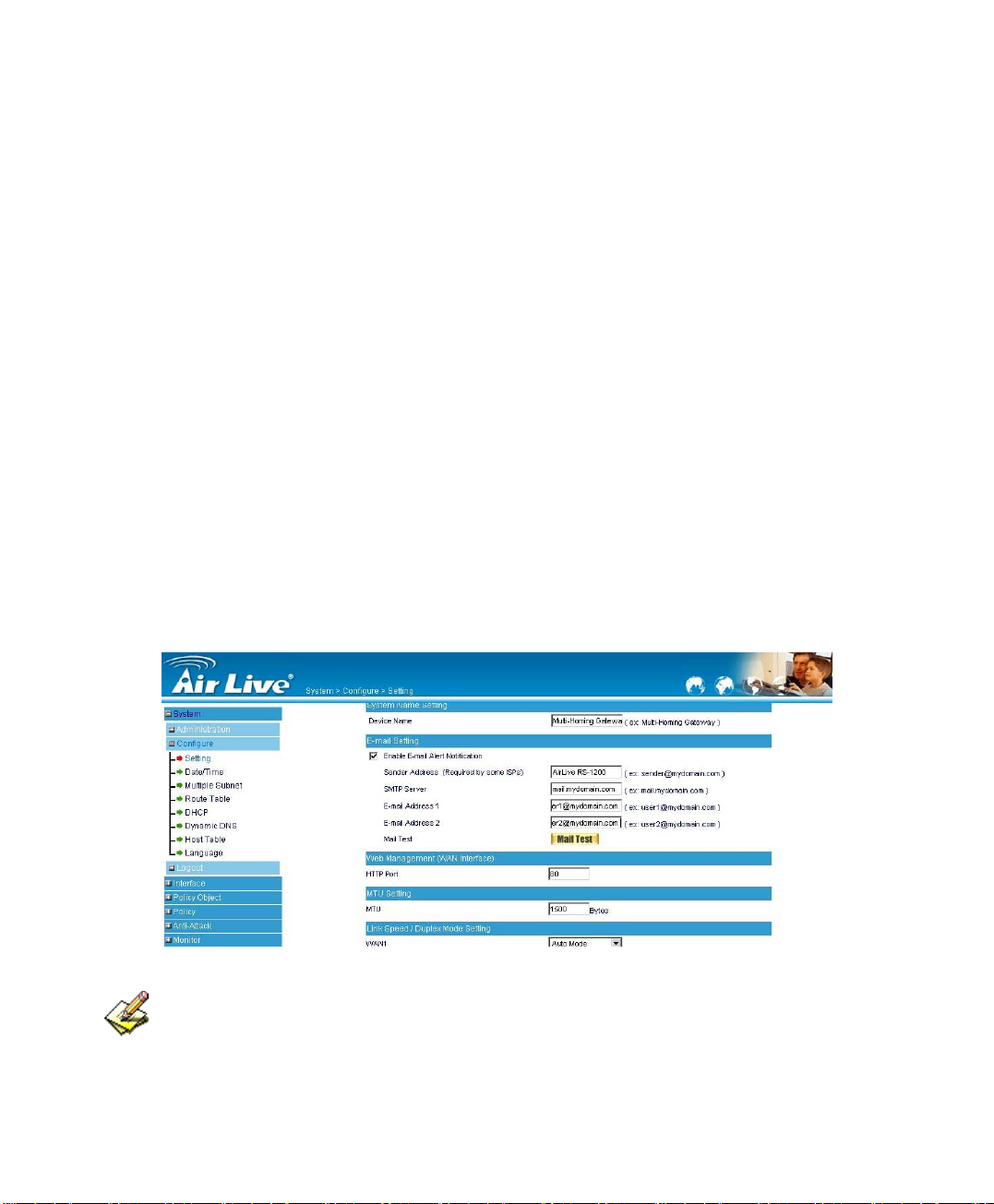
Email Settings:
Select Enable E-mail Alert Notification under E-mail Settings. This function will
enable the RS-1200 to send e-mail alerts to the System Administrator when the
network is being attacked by hackers or when emergency conditions occur. (It can
be set from Settings-Hacker Alert in System to detect Hacker Attacks)
Web Management (WAN Interface):
The System Manager can change the port number used by HTTP port
anytime. (Remote WebUI management)
After HTTP port has changed, if the administrator want to enter WebUI from
WAN, will have to change the port number of browser.
(For example: http://61.62.108.172:8080)
12
Page 13

MTU Setting:
It provides the Administrator to modify the networking package length anytime. Its
default value is 1500 Bytes
.
Link Speed / Duplex Mode:
By this function can set the transmission speed and mode of WAN Port when
connecting other device
.
Administration Packet Logging:
After enable this function; the RS-1200 will record packet which source IP or
destination address is RS-1200. And record in Traffic Log for System
Manager to inquire about.
13
Page 14

Define the required fields of Time Settings
Synchronize Time/Date:
Synchronizing the RS-1200 with the System Clock. The administrator can
configure the
Time Server (NTP) or by syncing to your computer’s clock.
RS-1200’s date and time by either syncing to an Internet Network
GMT:
International Standard Time (Greenwich Mean Time)
Define the required fields of Multiple Subnet
Forwarding Mode:
To display the mode that Multiple Subnet use. (NAT mode or Routing Mode)
WAN Interface Address:
The IP address that Multiple Subnet corresponds to WAN.
LAN Interface Address/Subnet Netmask:
The Multiple Subnet range
14
Page 15

NAT Mode:
It allows Internal Network to set multiple subnet address and connect with the
Internet through different WAN IP Addresses. For example:The lease line of a
company applies several real IP Addresses 168.85.88.0/24, and the company is
divided into R&D department, service, sales department, procurement department,
accounting department, the company can distinguish each department by different
subnet for the purpose of managing conveniently. The settings are as the
following:
1. R&D department subnet:192.168.1.1/24(LAN) ÅÆ 168.85.88.253(WAN)
2. Service department subnet:192.168.2.1/24(LAN) ÅÆ 168.85.88.252(WAN)
3. Sales department subnet:192.168.3.1/24(LAN) ÅÆ 168.85.88.251(WAN)
4. Procurement department subnet
192.168.4.1/24(LAN) ÅÆ 168.85.88.250(WAN)
5. Accounting department subnet
192.168.5.1/24(LAN) ÅÆ 168.85.88.249(WAN)
The first department (R&D department) had set while setting interface IP; the other four
ones have to be added in Multiple Subnet. After completing the settings, each
department uses the different WAN IP Address to connect to the Internet. The settings
of each department are as following:
Service Sales Procurement Accounting
IP Address 192.168.2.2~254 192.168.3.2~254 192.168.4.2~254 192.168.5.2~254
Subnet Netmask 255.255.255.0 255.255.255.0 255.255.255.0 255.255.255.0
Gateway 192.168.2.1 192.168.3.1 192.168.4.1 192.168.5.1
Routing Mode:
It is the same as NAT mode approximately but does not have to correspond to the
real WAN IP address, which let internal PC to access to Internet by its own IP.
(External user also can use the IP to connect with the Internet)
15
Page 16

Define the required fields of DHCP
Subnet:
The domain name of LAN
NetMask:
The LAN Netmask
Gateway:
The default Gateway IP address of LAN
Broadcast IP:
The Broadcast IP of LAN
Define the required fields of DDNS
Domain Name:
The domain name that provided by DDNS
WAN IP Address:
The WAN IP Address, which the domain name corresponds to.
Define the required fields of Host Table
Domain Name:
It can be set by System Manager. To let the internal user to access to the
information that provided by the host by this domain name
Virtual IP Address:
The virtual IP address respective to Host Table. It must be LAN or DMZ IP
address.
16
Page 17
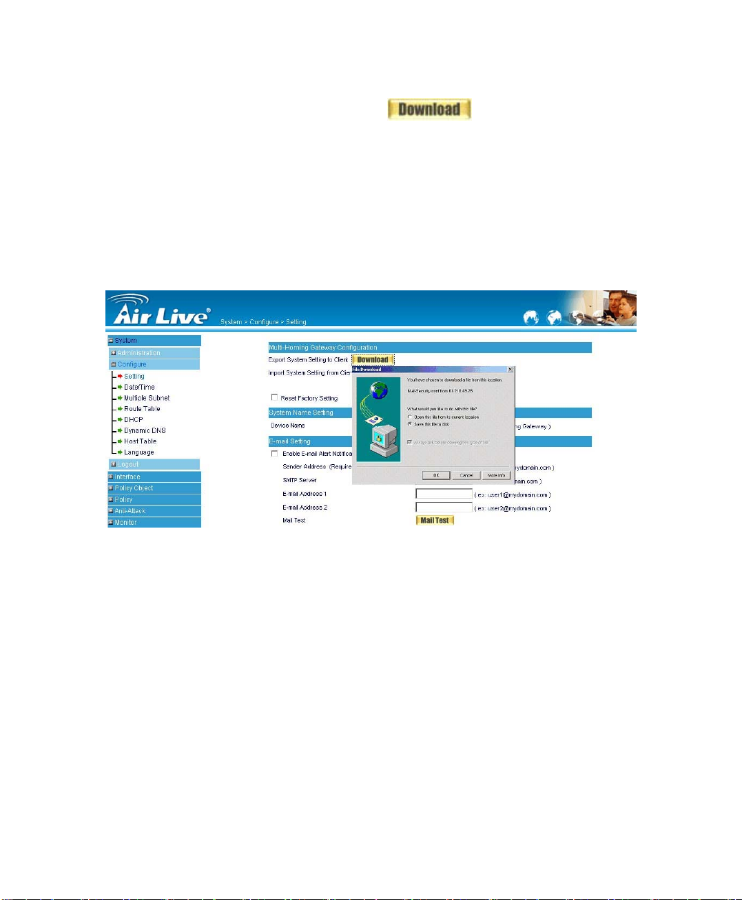
System Settings- Exporting
STEP 1﹒In System Setting WebUI, click on button next to
Export System Settings to Client.
STEP 2﹒When the File Download pop-up window appears, choose the destination
place where to save the exported file and click on Save. The setting value of
RS-1200 will copy to the appointed site instantly. (Figure2-1)
Figure2-1 Select the Destination Place to Save the Exported File
17
Page 18
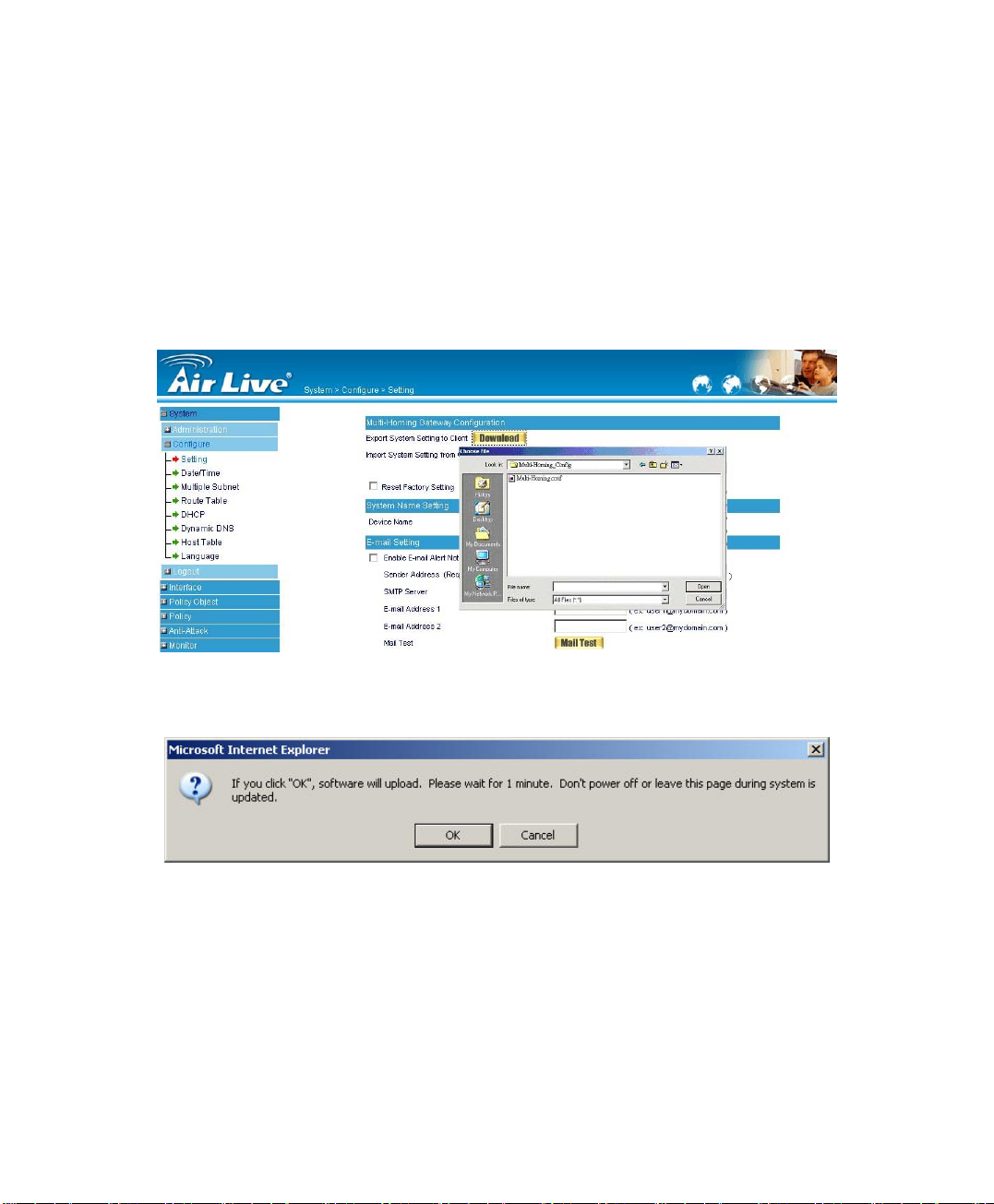
System Settings- Importing
STEP 1﹒In System Setting WebUI, click on the Browse button next to Import
System Settings from Client. When the Choose File pop-up window
appears, select the file to which contains the saved RS-1200 Settings,
then click OK. (Figure2-2)
STEP 2﹒Click OK to import the file into the RS-1200 (Figure2-3)
Figure 2-2 Enter the File Name and Destination of the Imported File
Figure 2-3 Upload the Setting File WebUI
18
Page 19
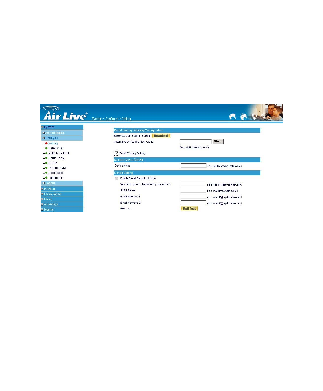
Restoring Factory Default Settings
STEP 1﹒Select Reset Factory Settings in RS-1200 Configuration WebUI
STEP 2﹒Click OK at the bottom-right of the page to restore the factory settings.
(Figure2-4)
Figure2-4 Reset Factory Settings
19
Page 20
Enabling E-mail Alert Notification
STEP 1﹒Select Enable E-mail Alert Notification under E-Mail Settings.
STEP 2﹒Device Name: Enter the Device Name or use the default value.
STEP 3﹒Sender Address: Enter the Sender Address. (Required by some ISPs.)
STEP 4﹒SMTP Server IP: Enter SMTP server’s IP address.
STEP 5﹒E-Mail Address 1: Enter the e-mail address of the first user to be notified.
STEP 6﹒E-Mail Address 2: Enter the e-mail address of the second user to be
notified. (Optional)
STEP 7﹒Click OK on the bottom-right of the screen to enable E-mail Alert Notification.
(Figure2-5)
Figure2-5 Enable E-mail Alert Notification
Click on Mail Test to test if E-mail Address 1 and E-mail Address 2 can receive the
Alert Notification correctly.
20
Page 21

Reboot RS-1200
STEP 1﹒Reboot RS-1200:Click Reboot button next to Reboot
RS-1200 Appliance.
STEP 2﹒A confirmation pop-up page will appear.
STEP 3﹒Follow the confirmation pop-up page; click OK to restart RS-1200.
(Figure2-6)
Figure2-6 Reboot RS-1200
21
Page 22
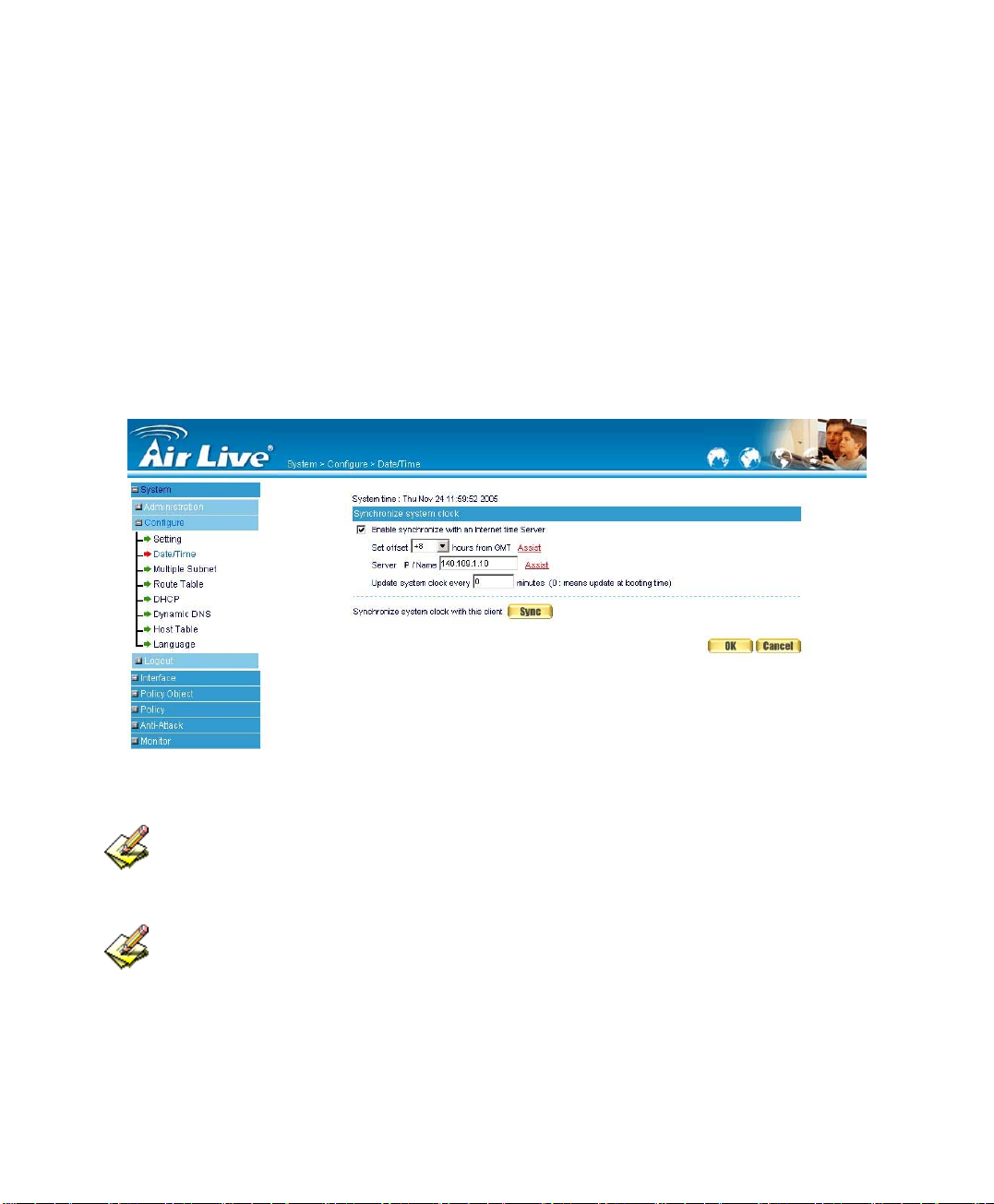
Date/Time Settings
STEP 1﹒Select Enable synchronize with an Internet time Server (Figure2-7)
STEP 2﹒Click the down arrow to select the offset time from GMT.
STEP 3﹒Enter the Server IP / Name with which you want to synchronize.
STEP 4﹒Set the interval time to synchronize with outside servers.
Figure2-7 System Time Setting
Click on the Sync button and then the RS-1200’s date and time will be
synchronized to the Administrator’s PC
The value of Set Offset From GMT and Server IP / Name can be looking for from
Assist.
22
Page 23

Multiple Subnet
Connect to the Internet through Multiple Subnet NAT or Routing Mode by the IP address
that set by the LAN user’s network card
Preparation
RS-1200 WAN1 (10.10.10.1) connect to the ISP Router (10.10.10.2) and the
subnet that provided by ISP is 162.172.50.0/24
To connect to Internet, WAN2 IP (211.22.22.22) connects with ATUR.
23
Page 24
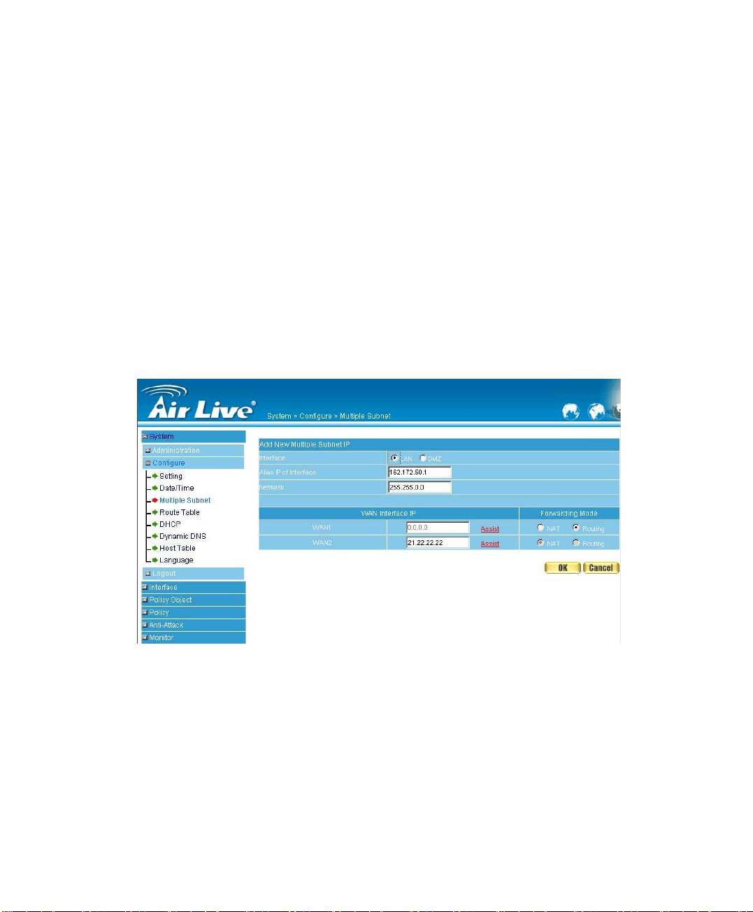
Adding Multiple Subnet
Add the following settings in Multiple Subnet of System function:
Click on New Entry
Alias IP of LAN Interface: Enter 162.172.50.1
Netmask:Enter 255.255.255.0
WAN1: Enter Interface IP 10.10.10.1, and choose Routing in
Forwarding Mode
WAN2:Enter Interface IP 211.22.22.22, and choose NAT in
Forwarding Mode
Click OK
Complete Adding Multiple Subnet (Figure2-8)
Figure 2-8 Add Multiple Subnet WebUI
24
Page 25
WAN1 and WAN2 Interface can use Assist to enter the data.
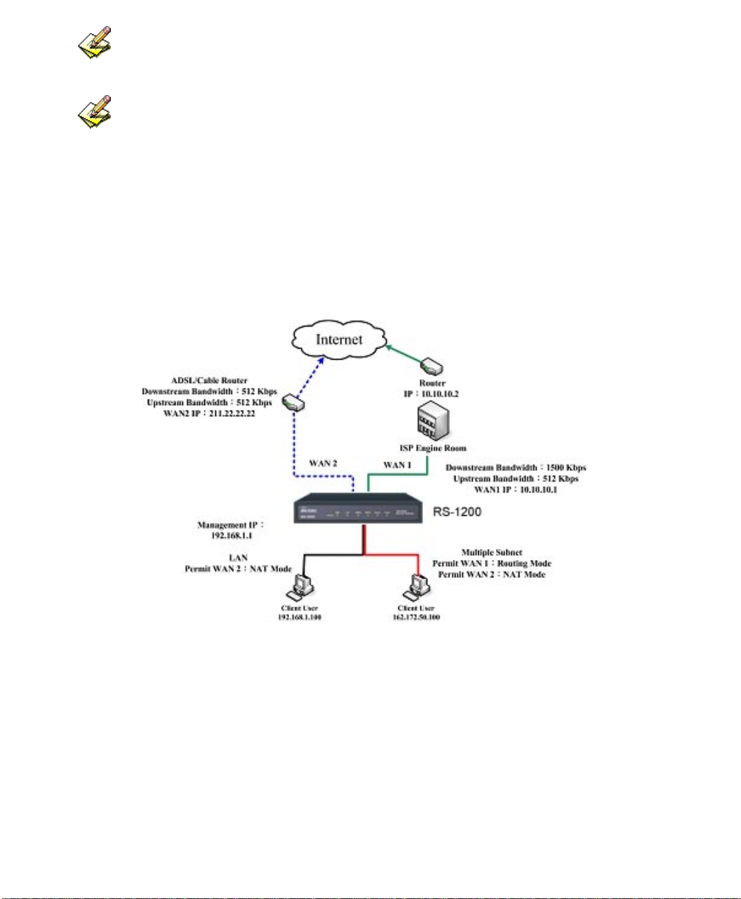
After setting, there will be two subnet in LAN: 192.168.1.0/24 (default LAN subnet)
and 162.172.50.0/24. So if LAN IP is:
˙192.168.1.xx, it must use NAT Mode to access to the Internet. (In Policy it only can
setup to access to Internet by WAN2. If by WAN1 Routing mode, then it cannot access
to Internet by its virtual IP)
˙162.172.50.xx, it uses Routing mode through WAN1 (The Internet Server can see your
IP 162.172.50.xx directly). And uses NAT mode through WAN2 (The Internet Server
can see your IP as WAN2 IP)(Figure2-9)
Figure 2-9 Multiple Subnet Network
The RS-1200’s Interface Status:
WAN1 IP: 10.10.10.1
WAN2 IP:211.22.22.22
LAN Port IP:192.168.1.1
LAN Port Multiple Subnet:162.172.50.1
25
Page 26

Route Table
To connect two different subnet router with the RS-1200 and
makes them to connect to Internet through RS-1200
Preparation
Company A: WAN1 (61.11.11.11) connects with ATUR to Internet
WAN2 (211.22.22.22) connects with ATUR to Internet
LAN subnet: 192.168.1.1/24
The Router1 which connect with LAN (10.10.10.1, support RIPv2)
its LAN subnet is 192.168.10.1/24
Company B: Router2 (10.10.10.2, support RIPv2), its LAN subnet is
192.168.20.1/24
Company A ‘s Router1 (10.10.10.1) connect directly with Company B ‘s
Router2 (10.10.10.2).
26
Page 27
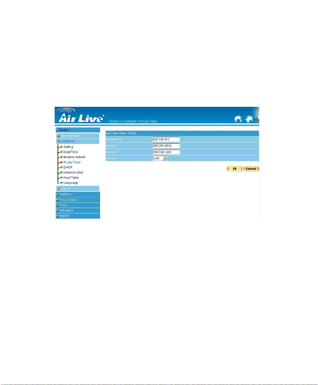
Route Table
STEP 1﹒Enter the following settings in Route Table in System function:
【Destination IP】: Enter 192.168.10.1
【Netmask】: Enter 255.255.255.0。
【Gateway】: Enter 192.168.1.252
【Interface】: Select LAN
Click OK (Figure 2-10)
Figure2-10 Add New Static Route1
STEP 2﹒Enter the following settings in Route Table in System function:
【Destination IP】: Enter 192.168.20.1
【Netmask】: Enter 255.255.255.0
【Gateway】: Enter 192.168.1.252
【Interface】: Select LAN
Click OK (Figure 2-11)
27
Page 28
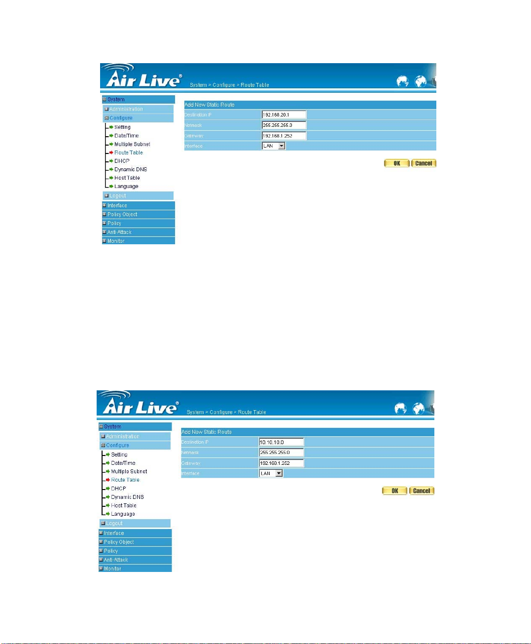
Figure2-11 Add New Static Route2
STEP 3﹒Enter the following setting in Route Table in System function:
【Destination IP】: Enter 10.10.10.0
【Netmask】: Enter 255.255.255.0
【Gateway】: Enter 192.168.1.252
【Interface】: Select LAN
Click OK (Figure 2-12)
Figure2-12 Add New Static Route3
28
Page 29
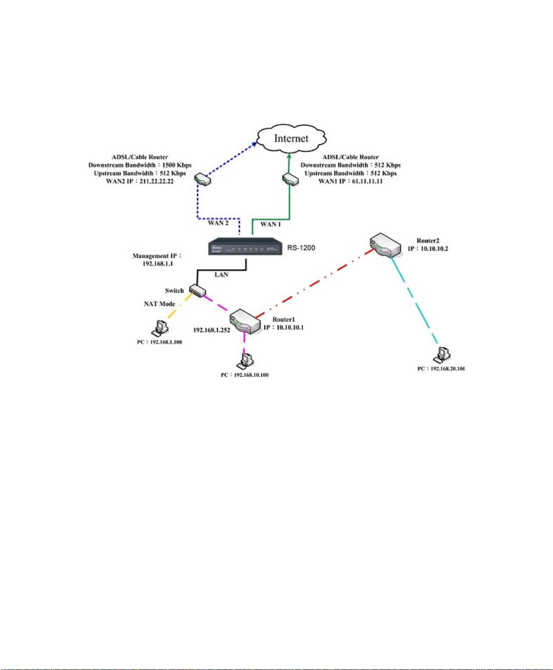
STEP 4﹒Adding successful. At this time the computer of 192.168.10.1/24,
192.168.20.1/24 and 192.168.1.1/24 can connect with each other and
connect to Internet by NAT (Figure 2-13)
Figure 2-13 Route Table Setting
29
Page 30

DHCP
STEP 1﹒Select DHCP in System and enter the following settings:
Domain Name:Enter the Domain Name
DNS Server 1: Enter the distributed IP address of DNS Server1.
DNS Server 2: Enter the distributed IP address of DNS Server2.
WINS Server 1: Enter the distributed IP address of WINS Server1.
WINS Server 2: Enter the distributed IP address of WINS Server2.
LAN Interface:
Client IP Address Range 1:
Enter the starting and the ending IP address dynamically assigning to
DHCP clients. The default value is 192.168.1.2 to 192.168.1.254 (it
must be in the same subnet)
Client IP Address Range 2:
Enter the starting and the ending IP address dynamically assigning to
DHCP clients. But it must in the same subnet as Client IP Address
Range 1 and the range cannot be repeated.
DMZ Interface: the same as LAN Interface. (DMZ works only if to
enable DMZ Interface)
Leased Time: Enter the leased time for Dynamic IP. The default time is
24 hours.
Click OK and DHCP setting is completed. (Figure2-14)
30
Page 31

Figure 2-14 DHCP WebUI
When selecting Automatically Get DNS, the DNS Server will lock it as LAN
Interface IP. (Using Occasion: When the system Administrator starts Authentication, the
users’ first DNS Server must be the same as LAN Interface IP in order to enter
Authentication WebUI)
31
Page 32

Dynamic DNS Settings
STEP 1﹒Select Dynamic DNS in System function (Figure2-15). Click New
Entry button
Service providers:Select service providers.
Automatically fill in the W AN 1/2 IP :Check to automatically fill in
the WAN 1/2 IP.。
User Name:Enter the registered user name.
Password:Enter the password
Domain name:Enter Your host domain name
Click OK to add Dynamic DNS. (Figure2-16)
Figure2-15 DDNS WebUI
Figure 2-16 Complete DDNS Setting
32
Page 33

Chart
Meaning Update
successfully
Incorrect
username or
Connecting
to server
Unknown error
password
If System Administrator had not registered a DDNS account, click on Sign up then
can enter the website of the provider.
If you do not select Automatically fill in the WAN IP and then you can enter a
specific IP in WAN IP. Let DDNS to correspond to that specific IP address.
33
Page 34

Host Table
STEP 1﹒Select Host Table in Settings function and click on New Entry
Domain Name: The domain name of the server
Virtual IP Address: The virtual IP address respective to Host Table
Click OK to add Host Table. (Figure2-17)
Figure2-17 Add New Host Table
To use Host Table, the user PC’s first DNS Server must be the same as the LAN
Port or DMZ Port IP of RS-1200. That is, the default gateway.
34
Page 35

Language
Select the Language version (English Version/ Traditional Chinese Version or
Simplified Chinese Version) and click OK. (Figure2-18)
Figure2-18 Language Setting WebUI
35
Page 36

Chapter 3
Interface
In this section, the Administrator can set up the IP addresses for
the office network.
The Administrator may configure the IP addresses of the LAN network,
the WAN 1/2 network, and the DMZ network.
The Netmask and gateway IP addresses are also configured in this section.
36
Page 37

Define the required fields of Interface
LAN:
Using the LAN Interface, the Administrator can set up the LAN network of
RS-1200.
Ping:
Select this function to allow the LAN users to ping the Interface IP Address.
HTTP:
Select to enable the user to enter the WebUI of RS-1200 from Interface IP.
WAN:
The System Administrator can set up the WAN network of RS-1200.
Balance Mode:
Auto: The RS-1200 will adjust the WAN 1/2 utility rate automatically according to
the downstream/upstream of WAN. (For users who are using various download
bandwidth)
Round-Robin: The RS-1200 distributes the W AN 1/2 download bandwid th 1:1, in
other words, it selects the agent by order. (For users who are using same
download bandwidths)
By Traffic: The RS-1200 distributes the WAN 1/2 download bandwidth by
accumulative traffic
.
By Session: The RS-1200distributes the WAN 1/2 download bandwidth by
saturated connections
.
By Packet: The RS-1200 distributes the WAN 1/2 download bandwidth by
accumulated packets and saturated connection
37
.
Page 38

Connect Mode:
Display the current connection mode:
PPPoE (ADSL user)
Dynamic IP Address (Cable Modem User)
Static IP Address
Saturated Connections:
Set the number for saturation whenever session numbers reach it,
the RS-1200 switches to the next agent on the list.
Priority:
Set priority of WAN for Internet Access.
Connection Test:
To test if the WAN network can connect to Internet or not. The testing ways are as
following:
ICMP:To test if the connection is successful or not by the Ping IP you set.
DNS:To test if the connection is successful or not by checking Domain
Name.
Upstream/Downstream Bandwidth:
The System Administrator can set up the correct Bandwidth of WAN network
Interface here.
Auto Disconnect:
The PPPoE connection will automatically disconnect after a length of idle time (no
activities). Enter the amount of idle time before disconnection in the field. Enter “0”
if you do not want the PPPoE connection to disconnect at all
38
.
Page 39

DMZ:
The Administrator uses the DMZ Interface to set up the DMZ network.
The DMZ includes:
NAT Mode:In this mode, the DMZ is an independent virtual subnet. This
virtual subnet can be set by the Administrator but cannot be the same as LAN
Interface.
Transparent Mode: In this mode, the DMZ and WAN Interface are in the
same subnet.
39
Page 40

We set up four Interface Address examples in this chapter:
No. Suitable
Situation
Ex1
Ex2
Ex3
Ex4
LAN
WAN
DMZ
DMZ
Example Page
Modify LAN Interface Settings
Setting WAN Interface Address
Setting DMZ Interface Address (NAT Mode)
Setting DMZ Interface Address (Transparent
41
42
50
51
Mode)
40
Page 41

Modify LAN Interface Settings
STEP 1﹒Select LAN in Interface and enter the following setting:
Enter the new IP Address and Netmask
Select Ping and HTTP
Click OK (Figure3-1)
Figure3-1 Setting LAN Interface WebUI
The default LAN IP Address is 192.168.1.1. After the Administrator setting the
new LAN IP Address on the computer , he/she have to restart the System to make the
new IP address effective. (when the computer obtain IP by DHCP)
Do not cancel WebUI selection before not setting Permitted IPs yet. It will cause
the Administrator cannot be allowed to enter the RS-1200 WebUI from LAN.
41
Page 42

Setting WAN Interface Address
STEP 1﹒Select WAN in Interface and click Modify in WAN1 Interface.
The setting of WAN2 Interface is almost the same as WAN1. The difference is that
WAN2 has a selection of Disable. The System Administrator can close WAN2 Interface
by this selection. (Figure3-2)
Figure3-2 Disable WAN2 Interface
42
Page 43

STEP 2﹒Setting the Connection Service (ICMP or DNS way):
ICMP:Enter an Alive Indicator Site IP (can select from Assist)
(Figure3-3)
DNS:Enter DNS Server IP Address and Domain Name (can select
from Assist) (Figure3-4)
Setting time of seconds between sending alive packet.
Figure3-3 ICMP Connection
Figure 3-4 DNS Service
Connection test is used for RS-1200 to detect if the WAN can connect or not. So
Alive Indicator Site IP, DNS Server IP Address, or Domain Name must be able to
the
use permanently. Or it will cause judgmental mistakes of the device.
43
Page 44

STEP 3﹒Select the Connecting way:
PPPoE (ADSL User) (Figure3-5):
1. Select PPPoE
2. Enter User Name as an account
3. Enter Password as the password
4. Select Dynamic or Fixed in IP Address provided by ISP.
If you select Fixed, please enter IP Address, Netmask, and Default
Gateway.
5. Enter Max. Downstream Bandwidth and Max. Upstream Bandwidth.
(According to the flow that user apply)
6. Select Ping and HTTP
7. Click OK (Figure3-6)
Figure3-5 PPPoE Connection
44
Page 45

Figure3-6 Complete PPPoE Connection Setting
If the connection is PPPoE, you can choose Service-On-Demand for WAN
Interface to connect automatically when disconnect; or to set up Auto Disconnect if
idle (not recommend)
45
Page 46

Dynamic IP Address (Cable Modem User) (Figure3-7):
1. Select Dynamic IP Address (Cable Modem User)
2. Click Renew in the right side of IP Address and then can obtain
IP automatically.
3. If the MAC Address is required for ISP then click on Clone MAC Address
to obtain MAC IP automatically.
4. Hostname: Enter the hostname provided by ISP.
5. Domain Name: Enter the domain name provided by ISP.
6. User Name and Password are the IP distribution method according to
Authentication way of DHCP+ protocol (like ISP in China)
7. Enter Max. Downstream Bandwidth and Max. Upstream Bandwidth
(According to the flow that user apply)
8. Select Ping and HTTP
9. Click OK (Figure3-8)
46
Page 47

Figure3-7 Dynamic IP Address Connection
Figure3-8 Complete Dynamic IP Connection Setting
47
Page 48

Static IP Address (Figure3-9)
1. Select Static IP Address
2. Enter IP Address, Netmask, and Default Gateway that provided by
ISP
3. Enter DNS Server1 and DNS Server2
In WAN2, the connecting of Static IP Address does not need to set DNS Server
4. Enter Max. Downstream Bandwidth and Max. Upstream Bandwidth
(According to the flow that user apply)
5. Select Ping and HTTP
6. Click OK (Figure3-10)
Figure3-9 Static IP Address Connection
48
Page 49

Figure3-10 Complete Static IP Address Connection Setting
When selecting Ping and WebUI on WAN network Interface, users will be able to
ping the RS-1200 and enter the WebUI W AN network. It may influence n etwork security.
The suggestion is to Cancel Ping and WebUI after all the settings have finished. And if
the System Administrator needs to enter UI from WAN, he/she can use Permitted IPs
to enter.
49
Page 50

Setting DMZ Interface Address (NAT Mode)
STEP 1﹒Click DMZ Interface
STEP 2﹒Select NAT Mode in DMZ Interface
Select NAT in DMZ Interface
Enter IP Address and Netmask
STEP 3﹒Select Ping and HTTP
STEP 4﹒Click OK (Figure3-11)
Figure3-11 Setting DMZ Interface Address (NAT Mode) WebUI
50
Page 51

Setting DMZ Interface Address (Transparent Mode)
STEP 1﹒Select DMZ Interface
STEP 2﹒Select Transparent Mode in DMZ Interface
Select DMZ_Transparent in DMZ Interface
STEP 1﹒Select Ping and HTTP
STEP 2﹒Click OK (Figure3-12)
Figure 3-12 Setting DMZ Interface Address (Transparent Mode) WebUI
In WAN, the connecting way must be Static IP Address and can choose
Transparent Mode in DMZ.
51
Page 52

Chapter 4
Address
The RS-1200 allows the Administrator to set Interface addresses of the
LAN network, LAN network group, WAN network, WAN network group,
DMZ and DMZ group.
An IP address in the Address Table can be an address of a computer or a
sub network. The Administrator can assign an easily recognized name to
an
IP address. Based on the network it belongs to, an IP address can be an
LAN
IP address, WAN IP address or DMZ IP address. If the Administrator needs
to create a control policy for packets of different IP addresses, he can first
add a new group in the LAN Group or the WAN Group and assign those IP
addresses into the newly created group. Using group addresses can
greatly simplify the process of building control policies.
With easily recognized names of IP addresses and names of address groups
shown in the address table, the Administrator can use these names as the source
address or destination address of control policies. The address table should be setup
before creating control policies, so that the Administrator can pick the names of correct
IP addresses from the address table when setting up control policies.
52
Page 53

Define the required fields of Address
Name:
The System Administrator set up a name as IP Address that is easily recognized.
IP Address:
It can be a PC’s IP Address or several IP Address of Subnet. Different network area
can be: Internal IP Address, External IP Address, and DMZ IP Address.
Netmask:
When correspond to a specific IP, it should be set as: 255.255.255.255.
When correspond to several IP of a specific Domain. Take 192.168.100.1 (C Class
subnet) as an example, it should be set as: 255.255.255.0.
MAC Address:
Correspond a specific PC’s MAC Address to its IP; it can prevent users changing
IP and accessing to the net service through policy without authorizing.
Get Static IP address from DHCP Server:
When enable this function and then the IP obtain from DHCP Server automatically
under LAN or DMZ will be distributed to the IP that correspond to the MAC
Address.
53
Page 54

We set up two Address examples in this chapter:
No Suitable
Situation
Ex1
Ex2
LAN
LAN Group
WAN
Example Page
Under DHCP circumstances, assign the specific IP
55
to static users and restrict them to access FTP net
service only through policy.
Set up a policy that only allows partial users to
58
connect with specific IP (External Specific IP)
54
Page 55

Under DHCP situation, assign the specific IP to static users and
restrict them to access FTP net service only through policy
STEP 1﹒Select LAN in Address and enter the following settings:
Click New Entry button (Figure4-1)
Name: Enter Rayearth
IP Address: Enter 192.168.3.2
Netmask: Enter 255.255.255.255
MAC Address : Enter the user’s MAC Address(00:B0:18:25:F5:89)
Select Get static IP address from DHCP Server
Click OK (Figure4-2)
Figure 4-1 Setting LAN Address Book WebUI
Figure4-2 Complete the Setting of LAN
55
Page 56

STEP 2﹒Adding the following setting in Outgoing Policy: (Figure4-3)
Figure 4-3 Add a Policy of Restricting the Specific IP to Access to Internet
STEP 3﹒Complete assigning the specific IP to static users in Outgoing Policy and
restrict them to access FTP net service only through policy: (Figure4-4)
Figure 4-4 Complete the Policy of Restricting the Specific IP to Access to Internet
56
Page 57

When the System Administrator setting the Address Book, he/she can choose
the way of clicking on
Address automatically.
to make the RS-1200 to fill out the user’s MAC
In LAN of Address function, the RS-1200 will default an Inside Any address
represents the whole LAN network automatically. Others like WAN, DMZ also have the
Outside Any and DMZ Any default address setting to represent the whole subnet.
The setting mode of WAN and DMZ of Address are the same as LAN; the only
difference is WAN cannot set up MAC Address.
57
Page 58

Setup a policy that only allows partial users to connect with
specific IP (External Specific IP)
STEP 1﹒Setting several LAN network Address. (Figure4-5)
Figure4-5 Setting Several LAN Network Address
58
Page 59

STEP 2﹒ Enter the following settings in LAN Group of Address:
Click New Entry (Figure 4-6)
Enter the Name of the group
Select the users in the Available Address column and click Add
Click OK (Figure 4-7)
Figure4-6 Add New LAN Address Group
Figure4-7 Complete Adding LAN Address Group
The setting mode of WAN Group and DMZ Group of Address are the same
as LAN Group.
59
Page 60

STEP 3﹒Enter the following settings in WAN of Address function:
Click New Entry (Figure4-8)
Enter the following data (Name, IP Address, Netmask)
Click OK (Figure4-9)
Figure4-8 Add New W A N A ddress
Figure4-9 Complete the Setting of WAN Address
60
Page 61

STEP 4﹒To exercise STEP1~3 in Policy (Figre4-10, 4-11)
Figure4-10 To Exercise Address Setting in Policy
Figure4-11 Complete the Policy Setting
The Address function really take effect only if use with Policy.
61
Page 62

Chapter 5
Service
TCP and UDP protocols support varieties of services, and each service consists
of a TCP Port or UDP port number, such as TELNET (23), SMTP (21), SMTP (25),
POP3 (110), etc. The RS-1200 includes two services:
Pre-defined Service and Custom Service.
The common-use services like TCP and UDP are defined in the Pre-defined
Service and cannot be modified or removed. In the custom menu, users can
define other TCP port and UDP port numbers that are not in the pre-defined menu
according to their needs. When defining custom services, the client port ranges
from 1024 to 65535 and the server port ranges from 0 to 65535
In this chapter, network services are defined and new network services can be
added. There are three sub menus under Service which are: Pre-defined,
Custom, and Group. The Administrator can simply follow the instructions below
to define the protocols and port numbers for network communication
applications. Users then can connect to servers and other computers through
these available network services.
How to use Service?
The Administrator can add new service group names in the Group option under
Service menu, and assign desired services into that new group. Using service
group the Administrator can simplify the processes of setting up control policies.
For example, there are 10 different computers that want to access 5 different
services on a server, such as HTTP, FTP, SMTP, POP3, and TELNET. Without the
help of service groups, the Administrator needs to set up 50 (10x5) control
policies, but by applying all 5 services to a single group name in the Service field,
it takes only one control policy to achieve the same effect as the 50 control
policies.
62
Page 63

Define the required fields of Service
Pre-defined WebUI’s Chart and Illustration:
Chart
Any Service
TCP Service, For example:FTP, FINGER, HTTP, HTTPS , IMAP,
SMTP, POP3, ANY, AOL, BGP, GOPHER, Inter Locator, IRC,
L2TP, LDAP, NetMeeting, NNTP, PPTP, Real Media, RLOGIN,
SSH, TCP ANY, TELNET, VDO Live, WAIS, WINFRAME,
X-WINDOWS, …etc.
UDP Service, For example:IKE, DNS, NTP, IRC, RIP, SNMP,
SYSLOG, TALK, TFTP, UDP-ANY, UUCP,…etc.
ICMP Service, Foe example:PING, TRACEROUTE…etc.
Illustration
New Service Name:
The System Manager can name the custom service.
Protocol:
The protocol type to be used in connection for device, such as TCP and UDP mode
Client Port:
The port number of network card of clients. (The range is 1024~65535, suggest to
use the default range)
Server Port:
The port number of custom service
63
Page 64

We set up two Service examples in this chapter:
A
No Suitable
Situation
Ex1
Ex2
Custom
Group
Example Page
llow external user to communicate with internal
65
user by VoIP through policy. (VoIP Port: TCP
1720, TCP 15325-15333, UDP 15325-15333)
Setting service group and restrict the specific
69
users only can access to service resource that
provided by this group through policy. (Group:
HTTP, POP3, SMTP, DNS)
64
Page 65

Allow external user to communicate with internal user by VoIP
through policy. (VoIP Port: TCP 1720, TCP 15328-15333, UDP
15328-15333)
STEP 1﹒Set LAN and LAN Group in Address function as follows: (Figure5-1, 5-2)
Figure5-1 Setting LAN Address Book WebUI
Figure5-2 Setting LAN Group Address Book WebUI
65
Page 66

STEP 2﹒Enter the following setting in Custom of Service function:
Click New Entry (Figure5-3)
Service Name: Enter the preset name VoIP
Protocol#1 select TCP, need not to change the Client Port, and set the
Server Port as: 1720:1720
Protocol#2 select TCP, need not to change the Client Port, and set the
Server Port as: 15328:15333
Protocol#3 select UDP, need not to change the Client Port, and set the
Server Port as: 15328:15333
Click OK (Figure5-4)
Figure5-3 Add User Define Service
Figure5-4 Complete the Setting of User Define Service of VoIP
66
Page 67

Under general circumstances, the range of port number of client is 1024-65535.
Change the client range in Custom of is not suggested.
If the port numbers that enter in the two spaces are different port number, then
enable the port number under the range between the two different port numbers (for
example: 15328:15333). And if the port number that enter in the two space are the same
port number, then enable the port number as one (for example: 1720:1720).
67
Page 68

STEP 3﹒Compare Service to Virtual Server. (Figure5-5)
Figure5-5 Compare Service to Virtual Server
STEP 4﹒Compare Virtual Server to Incoming Policy. (Figure5-6)
Figure5-6 Complete the Policy for External VoIP to Connect with Internal VoIP
STEP 5﹒In Outgoing Policy, complete the setting of internal users using VoIP to
connect with external network VoIP: (Figure5-7)
Figure5-7 Complete the Policy for Internal VoIP to Connect with External VoIP
Service must cooperate with Policy and Virtual Server that the function can
take effect
68
Page 69

Setting service group and restrict the specific users only can
access to service resource that provided by this group through
policy (Group: HTTP, POP3, SMTP, DNS)
STEP 1﹒Enter the following setting in Group of Service:
Click New Entry (Figure 5-8)
Name: Enter Main_Service
Select HTTP, POP3, SMTP, DNS in Available Service and click Add
Click OK (Figure 5-9)
Figure5-8 Add Service Group
69
Page 70

Figure5-9 Complete the setting of Adding Service Group
If you want to remove the service you choose from Selected Service,
choose the service you want to delete and click Remove.
70
Page 71

STEP 2﹒In LAN Group of Address function, Setting an Address Group that can
include the service of access to Internet. (Figure5-10)
Figure5-10 Setting Address Book Group
STEP 3﹒Compare Service Group to Outgoing Policy. (Figure5-11)
Figure5-11 Setting Policy
71
Page 72

Chapter 6
Schedule
In this chapter, the RS-1200 provides the Administrator to configure a
schedule for policy to take effect and allow the policies to be used at those
designated times. And then the Administrator can set the start time and
stop time or VPN connection in Policy or VPN. By using the Schedule
function, the Administrator can save a lot of management time and make
the network system most effective.
How to use the Schedule?
The system Administrator can use schedule to set up the device to carry
out the connection of Policy or VPN during several different time division
automatically.
72
Page 73

To configure the valid time periods for LAN users to access to
Internet in a day
STEP 1﹒Enter the following in Schedule:
Click New Entry (Figure6-1)
Enter Schedule Name
Set up the working time of Schedule for each day
Click OK (Figure6-2)
Figure6-1 Setting Schedule WebUI
Figure6-2 Complete the Setting of Schedule
73
Page 74

STEP 2﹒Compare Schedule with Outgoing Policy (Figure6-3)
Figure6-3 Complete the Setting of Comparing Schedule with Policy
The Schedule must compare with Policy .
74
Page 75

Chapter 7
QoS
By configuring the QoS, you can control the OutBound and InBound
Upstream/Downstream Bandwidth. The administrator can configure the
bandwidth according to the WAN bandwidth.
Downstream Bandwidth:To configure the Guaranteed Bandw idth and Maximum
Bandwidth.
Upstream Bandwidth:To configure the Guaranteed Bandwidth and Maximum
Bandwidth.
QoS Priority:To configure the priority of distributing Upstream/Downstream and
unused bandwidth.
The RS-1200 configures the bandwidth by different QoS, and selects the suitable
QoS through Policy to control and efficiently distribute bandwidth. The RS-1200
also makes it convenient for the administrator to make the Bandwidth to reach
the best utility. (Figure7-1, 7-2)
Figure7-1 the Flow Before Using QoS
75
Page 76

Figure7-2 the Flow After Using QoS (Max. Bandwidth: 400Kbps, Guaranteed Bandwidth: 200Kbps)
76
Page 77

Define the required fields of QoS
WAN:
Display WAN1 and WAN2
Downstream Bandwidth:
To configure the Guaranteed Bandwidth and Maximum Bandwidth according to the
bandwidth range you apply from ISP
Upstream Bandwidth:
To configure the Guaranteed Bandwidth and Maximum Bandwidth according to the
bandwidth range you apply from ISP
Priority:
To configure the priority of distributing Upstream/Downstream and unused
bandwidth.
Guaranteed Bandwidth:
The basic bandwidth of QoS. The connection that uses the IPSec Autokey of VPN
or Policy will preserve the basic bandwidth
.
Maximum Bandwidth:
The maximum bandwidth of QoS. The connection that uses the IPSec Autokey of
VPN or Policy, which bandwidth will not exceed the amount you set.
77
Page 78

We set up two QoS examples in this chapter:
No Suitable
Situation
Ex1
QoS
Example Page
Setting a policy that can restrict the user’s
79
downstream and upstream bandwidth.
78
Page 79

Setting a policy that can restrict the user’s downstream and
upstream bandwidth
STEP 1﹒Enter the following settings in QoS:
Click New Entry (Figure7-3)
Name: The name of the QoS you want to configure.
Enter the bandwidth in WAN1, WAN2
Select QoS Priority
Click OK (Figure7-4)
Figure7-3 QoS WebUI Setting
Figure7-4 Complete the QoS Setting
79
Page 80

STEP 2﹒Use the QoS that set by STEP1 in Outgoing Policy. (Figure7-5, 7-6)
Figure7-5 Setting the QoS in Policy
Figure7-6 Complete Policy Setting
When the administrator are setting QoS, the bandwidth range that can be set is the
value that system administrator set in the WAN of Interface. So when the System
Administrator sets the downstream and upstream bandwidth in WAN of Interface,
he/she must set up precisely.
80
Page 81

Chapter 8
Authentication
By configuring the Authentication, you can control the user’s
connection authority. The user has to pass the authentication
to access to Internet.
The RS-1200 configures the authentication of LAN’s user by setting
account and password to identify the privilege.
81
Page 82

Define the required fields of Authentication
Authentication Management
Provide the Administrator the port number and valid time to setup
RS-1200 authentication. (Have to setup the Authentication first)
Authentication Port: The internal user have to pass the authentication
to access to the Internet when enable RS-1200.
Re-Login if Idle: When the internal user access to Internet, can setup
the idle time after passing authentication. If idle time exceeds the time
you setup, the authentication will be invalid. The default value is 30
minutes.
URL to redirect when authentication succeed: The user who had
passes Authentication have to connect to the specific website. (It will
connect to the website directly which the user want to login) The default
value is blank.
Messages to display when user login: It will display the login
message in the authentication WebUI. (Support HTML) The default
value is blank (display no message in authentication WebUI)
z Add the following setting in this function: (Figure8-1)
Figure8-1 Authentication Setting WebUI
82
Page 83

z When the user connect to external network by Authentication,
the following page will be displayed: (Figure8-2)
Figure8-2 Authentication Login WebUI
83
Page 84

z It will connect to the appointed website after passing Authentication:
(Figure8-3)
Figure8-3 Connecting to the Appointed Website After Authentication
If the user ask for authentication positively, can enter the LAN IP by the
Authentication port number. And then the Authentication WebUI will be displayed.
84
Page 85

Auth-User Name:
The user account for Authentication you want to set.
Password:
The password when setting up Authentication.
Confirm Password:
Enter the password that correspond to Password
We set up four Authentication examples in this chapter:
No Suitable
Situation
Ex1
Auth User
Auth Group
Example Page
Setting specific users to connect with external
86
network only before passing the authentication
of policy.
(Adopt the built-in Auth User and Auth Group
Function)
85
Page 86

Setting specific users to connect with external network only
before passing the authentication of policy.
(Adopt the built-in Auth User and Auth Group Function)
STEP 1﹒Setup several Auth User in Authentication. (Figire8-4)
Figure8-4 Setting Several Auth Users WebUI
To use Authentication, the DNS Server of the user’s network card must be the
same as the LAN Interface Address of RS-1200.
86
Page 87

STEP 2﹒Add Auth User Group Setting in Authentication function and enter the
following settings:
Click New Entry
Name: Enter laboratory
Select the Auth User you want and Add to Selected Auth User
Click OK
Complete the setting of Auth User Group (Figure8-5)
Figure8-5 Setting Auth Group WebUI
87
Page 88

STEP 3﹒Add a policy in Outgoing Policy and input the Address and Authentication
of STEP 2 (Figure8-6, 8-7)
Figure8-6 Auth-User Policy Setting
Figure8-7 Complete the Policy Setting of Auth-User
88
Page 89

STEP 4﹒When user is going to access to Internet through browser, the authentication
UI will appear in Browser. After entering the correct user name and password,
click OK to access to Internet. (Figure8-8)
STEP 5﹒ If the user does not need to access to Internet anymore and is going to
logout, he/she can click LOGOUT Auth-User to logout the system. Or enter
the Logout Authentication WebUI (http:// LAN Interface: Authentication port
number/ logout.html) to logout (Figure8-9)
Figure8-8 Access to Internet through Authentication WebUI
Figure8-9 Logout Auth-User WebUI
89
Page 90

Chapter 9
Content Filtering
Content Filtering includes「URL」,「Script」,「P2P」,「IM」,「Download」.
【URL Blocking】: The administrator can set up to “Allow” or “Restrict”
entering the specific website by complete domain name, key words, and
met character (~and*).
【Script Blocking】: The access authority of Popup, ActiveX, Java,
Cookies
【P2P Blocking】: The authority of sending files by eDonkey, eMule, Bit
Torrent
【IM Blocking】: To restrict the authority of receiving video, file and
message from MSN Messenger, Yahoo Messenger, ICQ, QQ.
【Download Blocking】: To restrict the authority of download specific
sub-name file, audio, and some common video by http protocol directly.
90
Page 91

Define the required fields of Content Blocking
URL String:
The domain name that restricts to enter or only allow entering.
Popup Blocking:
Prevent the pop-up WebUI appearing
ActiveX Blocking:
Prevent ActiveX packets
Java Blocking:
Prevent Java packets
Cookies Blocking:
Prevent Cookies packets
eDonkey Blocking:
Prevent users to deliver files by eDonkey and eMule
BitTorrent Blocking:
Prevent users to deliver files by BitTorrent
91
Page 92

WinMX:
Prevent users to deliver files by WinMX
IM Blocking:
Prevent users to login MSN Messenger, Yahoo Messenger, ICQ, QQ, and Skype
Audio and Video Types:
Prevent users to transfer sounds and video file by http
Sub-name file Blocking:
Prevent users to deliver specific sub-name file by http
All Type:
Prevent users to send the Audio, Video types, and sub-name file…etc. by http
protocol.
92
Page 93

We set up five Content Blocking examples in this chapter:
No Suitable
Situation
Ex1
Ex2
URL Blocking
Script
Blocking
Ex3
Ex4
Ex5
P2P Blocking
IM Blocking
Download
Blocking
Example Page
Restrict the Internal Users only can access to
94
some specific Website
Restrict the Internal Users to access to Script
97
file of Website.
Restrict the Internal Users to access to the
99
file on Internet by P2P.
Restrict the Internal Users to send message,
101
files, video and audio by Instant Messaging.
Restrict the Internal Users to access to video,
103
audio, and some specific sub-name file from
http or ftp protocol directly.
93
Page 94

Restrict the Internal Users only can access to some specific
Website
※URL Blocking:
Symbol: ~ means open up; * means metacharacter
Restrict not to enter specific website:
or 「key word」of the website you want to restrict in URL String.
For example: www.kcg.gov.tw or go v.
Only open specific website to enter:
1. Add the website you want to open up in URL String. While adding, you
must enter the symbol “~” in front of the 「complete domain name」
or「key word」that represents to open these website to enter”.
For example: ~www.kcg.gov.tw or ~gov.
2. After setting up the website you want to open up, enter an order to
“forbid all” in the last URL String; means only enter * in URL String.
Enter the 「complete domain name」
Warning! The order to forbid all must be placed at last forever. If you want to
open a new website, you must delete the order of forbidding all and then
enter the new domain name. At last, re-enter the “forbid all” order again.
94
Page 95

STEP 1﹒Enter the following in URL of Content Filtering function:
Click New Entry
URL String: Enter ~yahoo, and click OK
Click New Entry
URL String: Enter ~google, and click OK
Click New Entry
URL String: Enter *, and click OK
Complete setting a URL Blocking policy (Figure9-1)
Figure9-1 Content Filtering Table
95
Page 96

STEP 2﹒Add a Outgoing Policy and use in Content Blocking function: (Figure9-2)
Figure9-2 URL Blocking Policy Setting
STEP 3﹒Complete the policy of permitting the internal users only can access to some
specific website in Outgoing Policy function: (Figure9-3)
Figure9-3 Complete Policy Settings
Afterwards the users only can browse the website that include “yahoo” and
“google” in domain name by the above policy.
96
Page 97

Restrict the Internal Users to access to Script file of Website
STEP 1﹒Select the following data in Script of Content Blocking function:
Select Popup Blocking
Select ActiveX Blocking
Select Java Blocking
Select Cookies Blocking
Click OK
Complete the setting of Script Blocking (Figure9-4)
Figure9-4 Script Blocking WebUI
97
Page 98

STEP 2﹒Add a new Outgoing Policy and use in Content Blocking function:
(Figure9-5)
Figure9-5 New Policy of Script Blocking Setting
STEP 3﹒Complete the policy of restricting the internal users to access to Script file of
Website in Outgoing Policy: (Figure9-6)
Figure9-6 Complete Script Blocking Policy Setting
The users may not use the specific function (like JAVA, cookie…etc.) to browse the
website through this policy. It can forbid the user browsing stock exchange
website…etc.
98
Page 99

Restrict the Internal Users to access to the file on Internet
by P2P
STEP 1﹒Select the following data in P2P of Content Blocking function:
Select eDonkey Blocking
Select BitTorrent Blocking
Select WinMX Blocking
Click OK
Complete the setting of P2P Blocking (Figure9-7)
Figure9-7 P2P Blocking WebUI
99
Page 100

STEP 2﹒Add a new Outgoing Policy and use in Content Blocking function:
(Figure9-8)
Figure9-8 Add New Policy of P2P Blocking
STEP 3﹒Complete the policy of restricting the internal users to access to the file on
Internet by P2P in Outgoing Policy: (Figure9-9)
Figure9-9 Complete P2P Blocking Policy Setting
P2P Transfer will occupy large bandwidth so that it may influence other users. And
P2P Transfer can change the service port free so it is invalid to restrict P2P Transfer by
Service. Therefore, the system manager must use P2P Blocking in Content Blocking
to restrict users to use P2P Transfer efficiently.
100
 Loading...