

Page 1

TIM
Three-wheeler bike
USER MANUAL
Page 2
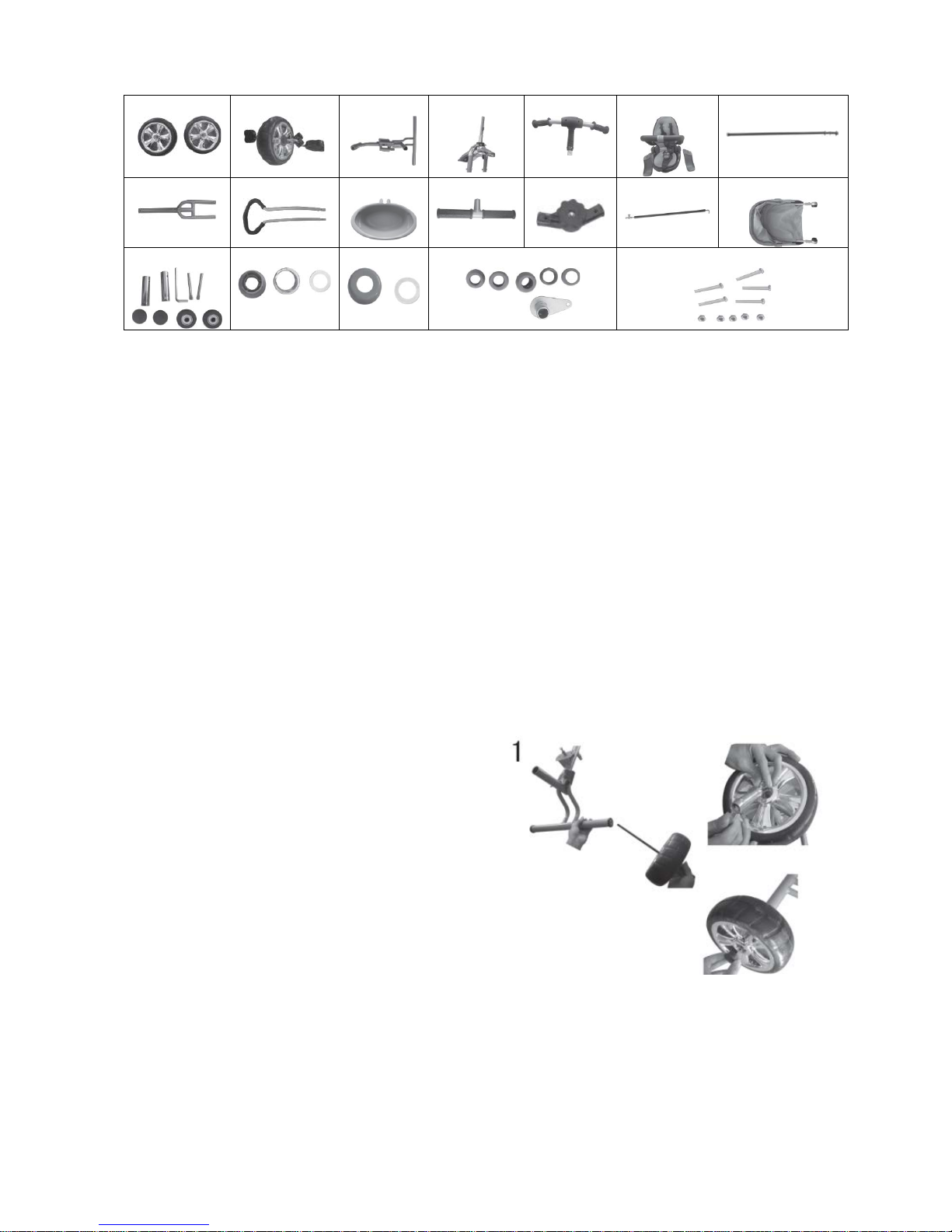
1. Accessories:
1.
2. 3. 4. 5. 6. 7.
8. 9.
10. 11. 12. 13. 14.
1. 2. 3. 4. 5.
1. Rear wheels
2. Front wheel
3. Frame
4. Front fork
5. Front handlebar
6. Seat
7. Rear axle
8. U-shaped tube
9. Rear handlebar
10. Basket
11. Footrest
12. Footrest adjuster
13. Handlebar connection tube
14. Canopy
1. Small bolts, tools, plastic parts (a)
2. Springs, gaskets (a), plastic parts (b)
3. Plastic parts (c), gaskets (b)
4. Metal and plastic parts (d)(e)(f)
5. Screws
2. Installation:
1. Back wheels installation:
Put the plastic cover (a) on the frame (3), mount
the rear wheel (1) on the rear axle (7) and slide the
rear axle (7) through the frame (3). Mount the
second rear wheel (1) on the rear axle (7) and use
tools to tighten the screws.
Page 3
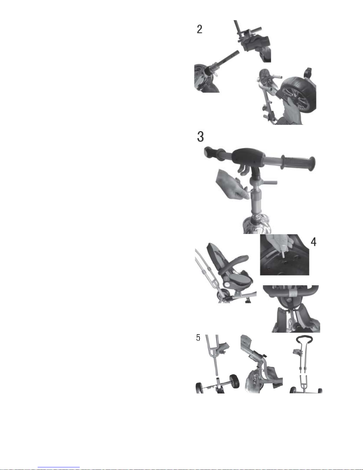
2. Front wheel installation:
Place the gasket (a) and the plastic cover (b) on
the front fork (4). Insert the fork (4) into the frame
(3).
Insert the stem of the front wheel tube (2) into the
front fork (4). Tighten all the construction with
screws.
3. Front handlebar installation:
Place the plastic cover (c) and gasket (b) on the
handlebar (5). Insert the handlebar into the frame
and push it so that you can tighten the screw.
4. Seat installation:
Position the seat (6) properly on the frame (3) and
secure it with screws. Slide the bolts of the plastic
footrests into the corresponding holes.
5. U-shape tube and rear handlebar
installation
Put the plastic cover (d) on the frame (3) and insert
the U-shaped tube (8) into the frame (3). Then,
place the metal part at the bottom and secure the
construction with the screw.
Insert the rear handlebar (9) into the guides of the
U-shaped tube (8) and secure it with screws.
Page 4
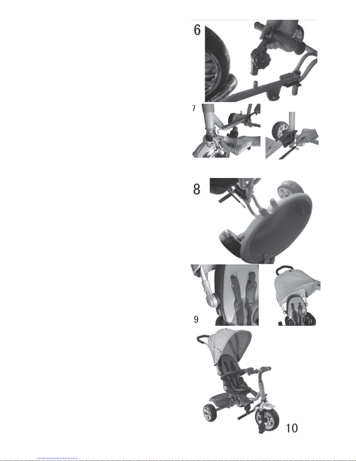
6. Footrest installation:
Combine the footrest (11) with the adjuster (12),
and then attach the whole part to the frame with a
screw.
7. Handlebar connection tube installation:
Hook the handlebar connection tube (13) onto the
metal element with an opening protruding from the
front handlebar (5). Then, hook the other end of the
tube with the metal element (with an opening) at
the bottom of the rear handlebar (9). Tighten the
screws from beneath according to the instruction in
the picture 7.
8. Basket installation:
Install the basket (10) on the rear part of the frame
(3) as it is shown in the picture 8.
9. Canopy installation:
Slide the tubes of the canopy (14) onto the plastic
guides and secure each of them with a screw.
10. Assembled tricycle
Page 5

3. Precautions:
◆ Age: older than 36 months.
◆ Weight limit: up to 25kg.
◆ Height range: 80-100cm
◆ Guardians are responsible for assembly, disassembly
and any adjustments to the device.
◆ Rear handlebar, footrest and seat belts are auxiliary elements, which purpose is to help a
parent / guardian to control the tricycle. Remove the auxiliary elements if you want the child to ride
the tricycle on their own.
◆ Do not stand on the seat or plastic footr ests.
◆ Do not use the tricycle on a slope or uneven road.
◆ Do not use the tricycle in heavy traffic streets.
◆ Store the tricycle in a dry place, protected from rain and snow.
◆ Do not modify the device.
◆ The rear handlebar should be controlled by a guardian.
◆ The plastic bag containing tools should be placed out of the sight of the child.
◆ Always keep the child in sight.
4. Maintenance:
To avoid injuries, often check the condition of the device.
1. Use a clean dry cloth to clean the body of the tricycle.
2. Make sure the screws are properly tightened and all the parts not damaged. If it is necessary,
replace the damaged parts.
3. In order to disassembly the tricycle, follow the assembly steps in reverse order.
4. Do not overload the device.
Note! All the pictures and descriptions in the manual have been submitted for illustrative purposes
only and are subject to change without prior notice.
Page 6

Instrukcja obsługi
LO-TIM
Page 7

1. Akcesoria:
1.
2. 3. 4. 5. 6. 7.
8. 9. 10. 11. 12. 13. 14.
1.
2. 3.
4. 5.
1. Tylne koła
2. Przednie koło
3. Rama
4. Przednie widełki
5. Kierownica przednia
6. Siedzisko
7. Oś tylna
8. U-kształtna rura
9. Kierownica tylna
10. Kosz
11. Podstawka na nogi
12. Regulator podstawki na nogi
13. Łącznik kierownicy
14. Daszek
1. Małe śruby, narzędzia, plastikowe części (a)
2. Sprężyny, uszczelki (a), plastikowe części (b)
3. Plastikowe części (c), uszczelki (b)
4. Metalowe i plastikowe części (d)(e)(f)
5. Śruby
2. Sposób montażu:
1. Montaż kół tylnych:
Nałóż plastikową osłonkę (a) na ramę (3),
zamontuj tylne koło (1) na tylnej osi (7) i
przepuść tylną oś (7) przez ramę (3). Załóż
drugie tylne koło (1) na tylną oś (7) i dokręć
na krętki używając narzędzi.
Page 8

2. Montaż przedniego koła:
Nałóż uszczelkę (a) i plastikową osłonkę (b)
na przednie widełki (4). Włóż widełki (4) w
ramę (3),
wstaw komponent przedniego koła (2) do
przednich widełek (4). Następnie dokręć
wszystko śrubami.
3. Montaż kierownicy przedniej:
Załóż osłonkę plastikową (c) oraz uszczelkę
(b) na kierownicę (5). Włóż kierownicę w
ramę i dociśnij, tak aby można było
przykręcić śrubę.
4. Instalacja siedziska:
Ustaw siedzisko (6) w pasujący sposób na
ramię (3), następnie dokręć je za pomocą
śrub. Wsuń plastikowe podstawki na nogi na
swoje miejsce.
5. Montaż U-kształtnej rury i
kierownicy tylnej:
Nałóż plastikową osłonkę (d) na ramę (3),
włóż U-kształtną rurę (8) w ramę (3),
następnie od dołu nałóż element metalowy i
zabezpiecz śrubą.
Włóż kierownicę tylną (9) w prowadniki Ukształtnej rury (8) i zabezpiecz ją śrubami.
Page 9

6. Montaż podstawki na nogi:
Połącz podstawkę na nogi (11) z
regulatorem (12), następnie przymocuj
całość do ramy za pomocą śruby.
7. Montaż łącznika kierownicy:
Zaczep łącznik kierownicy (13) za metalowy
element z otworem, wychodzący z
kierownicy przedniej (5), następnie połącz
łącznik z elementem metalowym z otworem,
znajdującym się na spodzie osi kierownicy
tylnej (9). Dokręć śruby od spod, tak jak na
zdjęciu nr.7.
8. Montaż kosza:
Kosz (10) należy zamontować na ramie (3)
w końcowej części. Tak jak przedstawia to
zdjęcie nr.8.
9. Montaż daszka:
Rurki daszka (14) należy wsunąć na
plastikowe prowadniki a następnie
zabezpieczyć śrubą z oby stron.
Page 10

10. Złożony trójkołowiec.
3. Środki ostrożności:
◆ Przedział wiekowy: powyżej 36 miesięcy.
◆ Limit wagowy: do 25kg.
◆ Zakres Wysokość: 80-100cm
◆ Opiekunowie są odpowiedzialni za montaż, demontaż
oraz regulację urządzenia.
◆ Uchwyt, podnóżek i pasy bezpieczeństwa są to elementy pomocnicze
dla dziecka, aby dziecko mogło samodzielnie obsługiwać urządzenie, należy zdemontować elementy
pomocnicze.
◆ Nie należy stawać na siedzeniu i podstawkach na nogi.
◆ Nie używaj go na zboczu góry lub nierównej drodze.
◆ Nie używaj go na hałaśliwej, ruchliwej ulicy.
◆ Należy przechowywać w suchym miejscu, nie narażonym na opady deszczu lub śniegu.
◆ Nie wolno modyfikować urządzenia.
◆ Uchwyt powinien być kontrolowany przez opiekuna.
◆ Plastikowa torba zawierająca narzędzia, powinna znajdować się poza zasięgiem wzroku dziecka.
◆ Podczas zabawy, mniej dziecko ciągle w zasięgu wzroku.
4.Konserwacja:
Aby uniknąć zranienia dziecka, należy często sprawdzać utrzymanie urządzenia.
1. Podczas czyszczenia korpusu, należy używać suchej szmatki.
2. Sprawdź regularnie czy śruby nie są luźne, części uszkodzone, w razie potrzeby wymień uszkodzone
części.
3. Czynności demontażu, należy wykonać odwrotnie do instrukcji montażu.
4. Unikać przeciążenia urządzenia.
Uwaga! Zdjęcia i opisy zawarte w instrukcji są poglądowe i mogą ulec zmianie bez wcześniejszego
informowania klienta.
Page 11

Declaration of Conformity
We, the undersigned:
Manufacturer:
BrandLine Group Sp. z o.o.
Address, City:
ul. Dziadoszańska 10
61-248 Poznań
Country: Polska
Declare the following apparatus:
Products name: Three-wheeler Bike
Brand and Model name: LO-Tim
Hereby we confirm above product compliance with the European directive of CE
Below standards were tested and passed:
CE
EN71-1:2014
EN71-2:2011
EN71-3:2013
Release date: 21.09.2015
May be sold in: BE CZ DK DE EE IE EL ES FR HR IT LV LT HU MT NL AT PL PT RO SI SK FI SE UK
The original document is located in the headquarter BrandLine Group Sp. z o.o.
ul. Dziadoszańska 10, 61-248 Poznań, Poland.
Page 12

 Loading...