

Page 1
Wireless N 3G/3.5G Mobile Router
Model # AR660W3G
User’s Manual
Ver. 1A
Page 2

Federal Communication Commission
Interference Statement
FCC Part 15
This equipment has been tested and found to comply with the limits for a Class B digital
device, pursuant to Part 15 of FCC Rules. These limits are designed to provide
reasonable protection against harmful interference in a residential installation. This
equipment generates, uses, and can radiate radio frequency energy and, if not installed
and used in accordance with the instructions, may cause harmful interference to radio
communications. However, there is no guarantee that interference will not occur in a
particular installation. If this equipment does cause harmful interference to radio or
television reception, which can be determined by turning the equipment off and on, the
user is encouraged to try to correct the interference by one or more of the following
measures:
1. Reorient or relocate the receiving antenna.
2. Increase the separation between the equipment and receiver.
3. Connect the equipment into an outlet on a circuit different from that to which the
receiver is connected.
4. Consult the dealer or an experienced radio technician for help.
FCC Caution
This equipment must be installed and operated in accordance with provided instructions
and a minimum 20 cm spacing must be provided between computer mounted antenna
and person’s body (excluding extremities of hands, wrist and feet) during wireless
modes of operation.
This device complies with Part 15 of the FCC Rules. Operation is subject to the following
two conditions: (1) this device may not cause harmful interference, and (2) this device
must accept any interference received, including interference that may cause undesired
operation.
Any changes or modifications not expressly approved by the party responsible for
compliance could void the authority to operate equipment.
Federal Communication Commission (FCC) Radiation Exposure Statement
This equipment complies with FCC radiation exposure set forth for an uncontrolled
environment. In order to avoid the possibility of exceeding the FCC radio frequency
exposure limits, human proximity to the antenna shall not be less than 20cm (8 inches)
during normal operation.
The antenna(s) used for this transmitter must not be co-located or operating in
conjunction with any other antenna or transmitter.
The equipment version marketed in US is restricted to usage of the channels 1-11 only.
Page 3

Table of Contents
FEDERAL COMMUNICATION COMMISSION INTERFERENCE STATEMENT ......................... 2
TABLE OF CONTENTS ............................................................................................................... 3
CHAPTER 1 INTRODUCTION..................................................................................................... 6
1.1 FEATURES...................................................................................................................................6
1.2 PACKAGE CONTENTS...................................................................................................................6
1.3 ROUTER INTERFACE ....................................................................................................................6
CHAPTER 2 CONNECTING THE ROUTER................................................................................. 9
2.1 BUILDING NETWORK CONNECTION...............................................................................................9
2.2 CONFIGURING THE ROUTER – SETUP WIZARD............................................................................10
2.3 CONNECTING TO THE ROUTER WIRELESSLY...............................................................................23
2.4 TROUBLESHOOTING...................................................................................................................26
CHAPTER 3 USING WEB CONFIGURATION UTILITY............................................................. 28
3.1 NETWORK .................................................................................................................................29
3.1.1 WAN ............................................................................................................................. 29
3.1.2 3G/3.5G........................................................................................................................29
3.1.3 LAN...............................................................................................................................30
3.1.4 DNS..............................................................................................................................33
3.1.5 DDNS............................................................................................................................ 34
3.1.6 NAT............................................................................................................................... 35
3.2 WIRELESS.................................................................................................................................36
3.2.1 Basic Settings............................................................................................................... 36
3.2.2 Wireless Security.......................................................................................................... 37
3.2.2.1 WEP........................................................................................................................... 38
3.2.2.2 WPA Pre-share Key .................................................................................................. 39
3.2.2.3 WPA RADIUS............................................................................................................ 40
3.2.3 MAC Control................................................................................................................. 41
3.2.4 Advanced Settings........................................................................................................ 42
3.2.5 WPS.............................................................................................................................. 44
3.3 APPLICATION & GAMING ............................................................................................................48
3.3.1 Port Forwarding............................................................................................................ 48
3.3.2 Port Triggering.............................................................................................................. 49
3.3.3 DMZ.............................................................................................................................. 51
3.3.4 ALG Settings................................................................................................................. 53
3.3.5 QoS............................................................................................................................... 54
3.4 ACCESS RESTRICTIONS.............................................................................................................58
3.4.1 Access Control.............................................................................................................. 58
3.4.1.1 MAC Filtering............................................................................................................. 59
3.4.1.2 IP Filtering.................................................................................................................. 60
3.4.2 URL Filtering................................................................................................................. 62
Page 4

3.5 SECURITY..................................................................................................................................64
3.5.1 Firewall ......................................................................................................................... 64
3.5.2 VPN Pass through........................................................................................................ 64
3.5.3 DoS (Denial-of-Service)................................................................................................ 65
3.6 ADMINISTRATION .......................................................................................................................66
3.6.1 Time.............................................................................................................................. 66
3.6.2 Password...................................................................................................................... 67
3.6.3 Remote Management................................................................................................... 68
3.6.4 Firmware Upgrade........................................................................................................ 69
3.6.5 System Settings............................................................................................................ 70
3.6.6 Reboot.......................................................................................................................... 70
3.6.7 System Log................................................................................................................... 71
3.6.8 Security Log.................................................................................................................. 71
3.6.9 Statistics ....................................................................................................................... 72
3.6.10 UPnP .......................................................................................................................... 73
3.7 STATUS.....................................................................................................................................74
3.7.1 Internet Connection Status........................................................................................... 74
3.7.2 LAN Status.................................................................................................................... 74
3.7.3 Wireless Status............................................................................................................. 75
3.7.4 System Status............................................................................................................... 75
3.7.5 Modem Info................................................................................................................... 75
TECHNICAL SUPPORT............................................................................................................. 77
Page 5

Chapter 1 Introduction
Congratulations on your purchase of AR660W3G Wireless N 3G/3.5G Mobile Router. This
product is specifically designed for business travelers or SOHO needs. It provides an extended
WAN solution, 3G Mobile USB modem card for Internet surfing besides regular Cable or DSL
modem and is easy to share the Internet connectivity wherever 3G mobile Internet service is
available. It is recommended to use with AirLink101® Wireless N products to provide the best
performance. The high speed of up to 300Mbps* combined with extended wireless coverage
delivers fast and reliable connections for all of your networking applications.
A full range of security features such as WEP, WPA-PSK, and WPA2-PSK provide the highest
level of wireless network security. The web-based Setup Wizard allows you to set up the router
with an easy-to-use user interface. Meanwhile, the AR660W3G works with 802.11n / g / b
network devices which ensures compatibility with your existing wireless products.
1.1 Features
• Share Broadband Internet connection from either your 3G USB Modem or Cable/DSL
• Industry’s highest wireless data rate of up to 300Mbps* with 802.11n draft 2.0
• Built-in four LAN ports (10/100M) and one WAN port (10/100M)
• Supports UMTS/HSDPA/EVDO 3G/3.5G USB modem
• Two 3dBi external antennas for wider coverage and stronger signal strength to eliminate
dead spots
• 64-bit/128-bit WEP encryption, Pre-shared Key (PSK), and Wi-Fi Protected Access
(WPA2 and WPA) support provide full protection for your wireless connection
• Stronger signal strength increases the reliability and speed of wireless connections
• Great for environments with higher wireless data traffic requirements
• Fully backward-compatible with 802.11b/g devices
• Works best with AirLink101® Wireless N and 300N Adapters
1.2 Package Contents
Before you start to use this router, please check if there’s anything missing in the package, and
contact your dealer of purchase to claim for missing items:
• Wireless N 3G/3.5G Mobile Router
• Quick installation guide
• Manual CD
• A/C power adapter
• Ethernet Cable
1.3 Router Interface
Front Panel LEDs
6
Page 6
LED
POWER On Router is powered on.
WLAN
WAN
LNK/ACT
USB
LNK/ACT
LAN 1-4
LNK/ACT
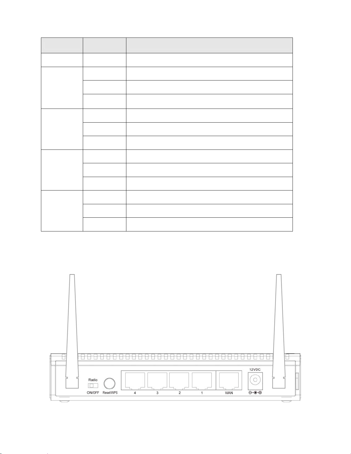
Back Panel
Light
Status
On WPS setup is in progress.
Off Wireless network is switched off.
Flashing
On WAN port is connected.
Off WAN port is not connected.
Flashing WAN port is transferring or receiving data.
On USB modem is connected
Off USB modem is not connected
Flashing USB modem is transferring or receiving data.
On LAN port is connected.
Off LAN port is not connected.
Flashing LAN port is transferring or receiving data.
Description
Wireless network is ready and WPS setup is not in
progress.
Antenna A
7
Antenna B
Page 7

Item
Name
Description
Antenna
A/B
Radio
ON/OFF
Reset /
WPS
1 - 4 Local Area Network (LAN) ports 1 to 4.
WAN Wide Area Network (WAN / Internet) port.
Power Power connector, connects to A/C power adapter.
These antennas are 3dBi dipole antennas.
Switch the button to activate or deactivate the Router’s wireless function.
Reset the router to factory default settings (clear all settings) or start security
synchronization function (WPS). Press this button and hold for 10 seconds to
restore all settings to factory defaults. Press this button for no longer than 1
second to start security synchronization.
8
Page 8
Chapter 2 Connecting the Router
2.1 Building Network Connection
Note: Prior to connecting the router, be sure to power off your computer, DSL/Cable modem(if
applicable), and the router.
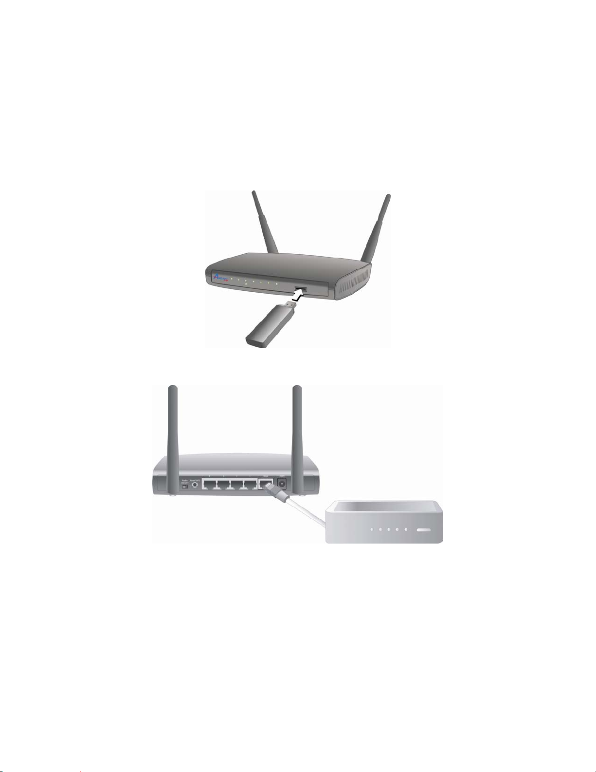
Step 1
Option 1 Plug the 3G/3.5G USB modem into the USB slot on the front panel of the router.
3G USB Modem
Option 2 Connect one end of a network cable to the WAN port of the router and connect the
other end of the cable to the DSL/Cable modem. Power on the modem.
Cable/DSL Modem
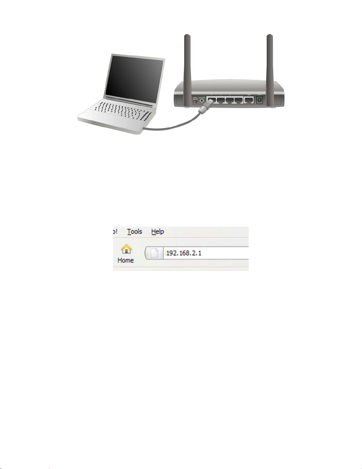
Step 2 With another network cable, connect one end of the cable to your computer’s Ethernet
port and connect the other end to one of the LAN ports of the router. (After setup finishes, you
can remove the network cable between the computer and router if you want to use wireless
connection.)
9
Page 9
Step 3 Plug the power adapter to the router and connect it to an outlet or power strip.
Step 4 Power on your computer.
Step 5 Make sure the Power, WAN or USB, WLAN, and the LAN port that the computer is
connected to are lit. If not, try the above steps again.
2.2 Configuring the Router – Setup Wizard
Step 1 Open the web browser (i.e. Internet Explorer or Mozilla Firefox) and type 192.168.2.1 in
the URL address bar and press Enter.
Step 2 Enter admin for both the user name and password and click OK.
10
Page 10
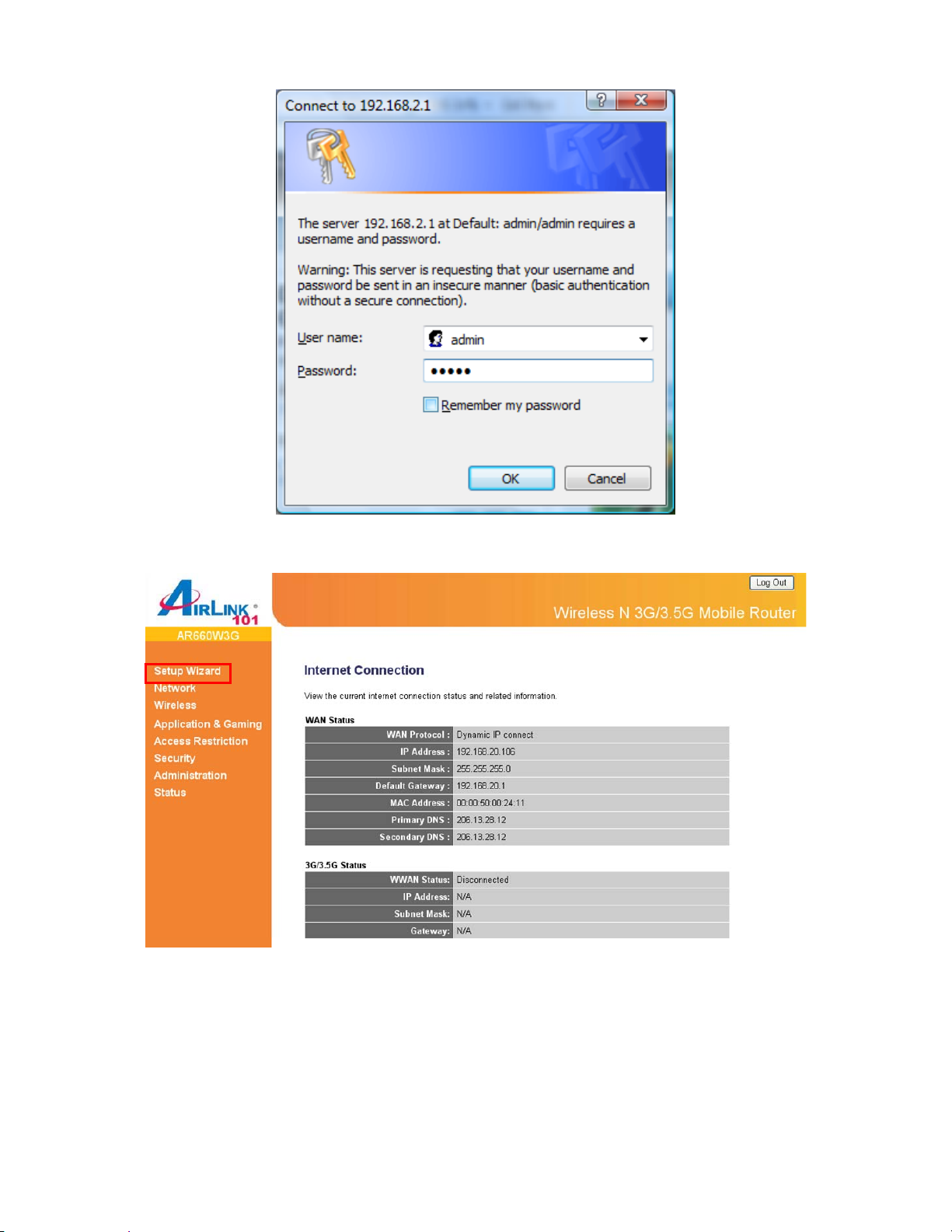
Step 3 Click on Setup Wizard.
Step 4 Configure the Time Zone Settings of the Router. Click Next.
11
Page 11
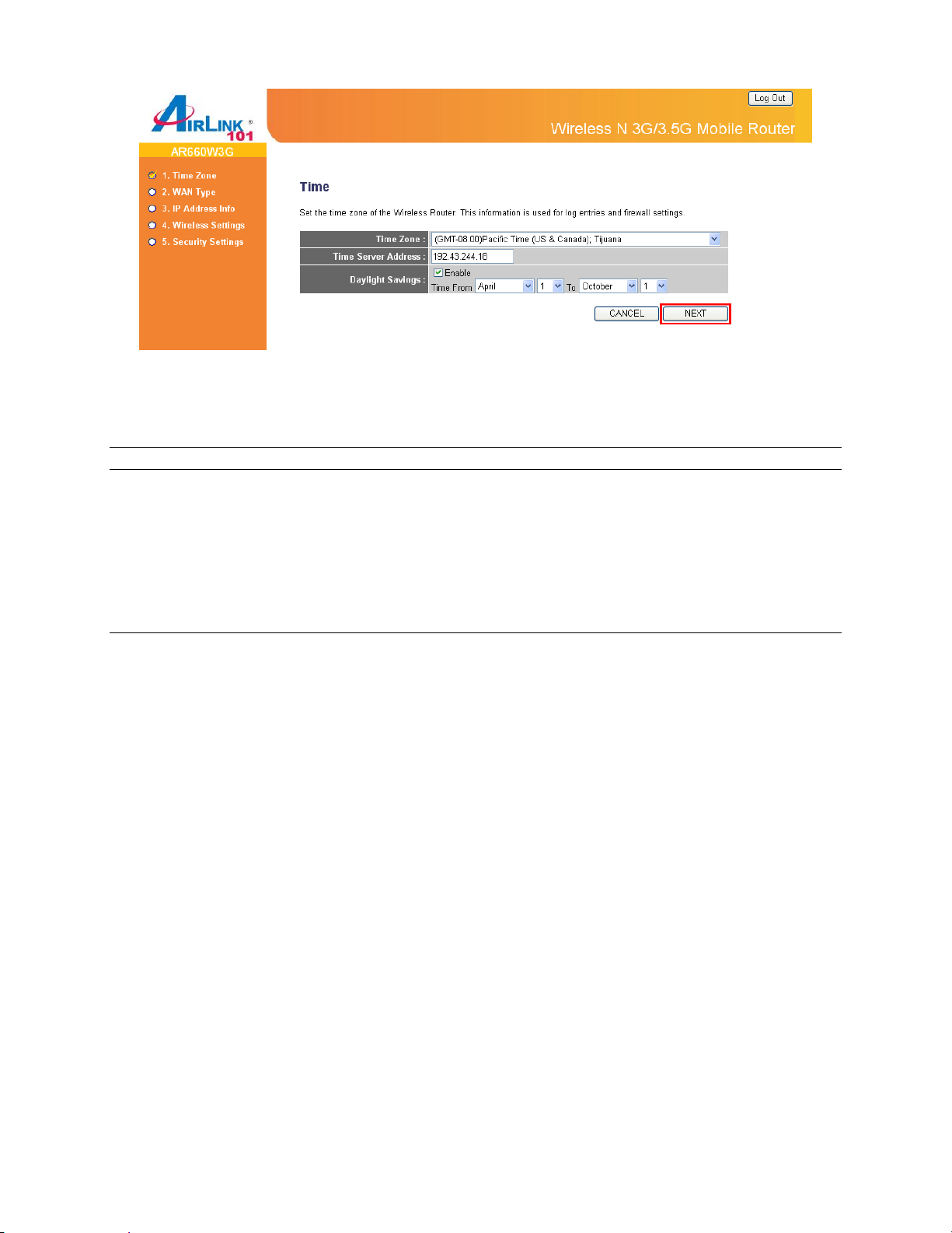
The Time Zone allows your router to base its time on the settings configured here, this will affect
functions such as Log entries and Firewall settings.
Parameter Description
Time Zone You can select your local time zone here. The router will sync
time according to your time zone selection.
Time Server Address Input the IP address / host name of time server here
Daylight Saving If the country you live uses daylight saving, please check the
Enable box and choose the duration of daylight saving.
Step 5 Please choose the broadband (Internet connection) type you are using in this page. If
you’re not sure, please contact your Internet service provider. A wrong Internet connection type
will cause connection problem, and you may not be able to connect to internet.
12
Page 12
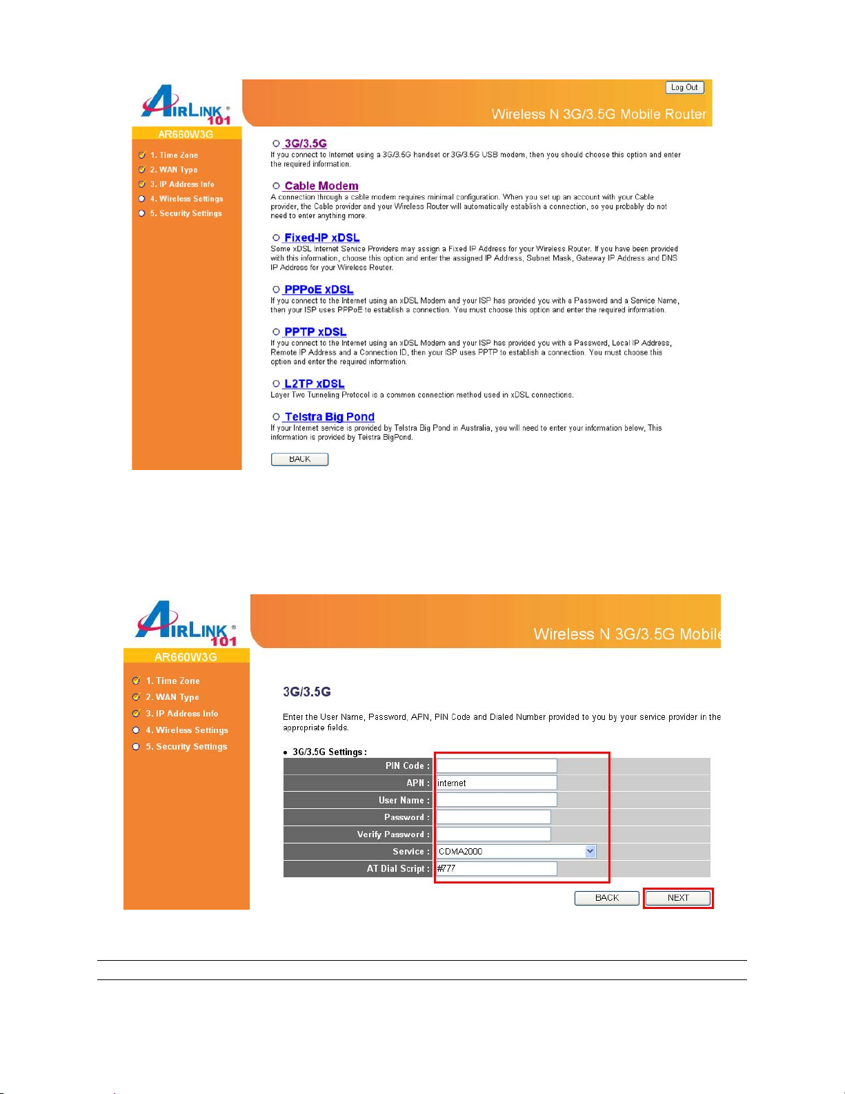
3G/3.5G
Click on 3G/3.5G if you are connecting to Internet through a 3G USB modem.
When the 3G/3.5G detailed settings come up, enter the Internet connection parameters if it is
required by your wireless 3G Internet Service Provider and then click NEXT.
Note: The setting shown above is for Verizon Wireless USB720 Modem.
Parameter Description
13
Page 13
PIN Code Please input Pin Code for your UMTS or HSDPA or EVDO
connection, this is optional, and only required if your service
provider asks you to do so.
APN Please input the APN code assigned by your Internet service
provider here.
User Name Please input user name assigned by your Internet service
provider here.
Password Please input password assigned by your Internet service
provider here.
Verify Password Please input password again for confirmation.
Service Please select your service type between CDMA2000 or 3G/3.5G
Only. You may try both service types if you are not sure which
one your USB modem card uses.
AT Dial Script Please input Dialed Number for your UMTS or HSDPA
connection, the default is *99#. This field should not be altered
except when required by your service provider.
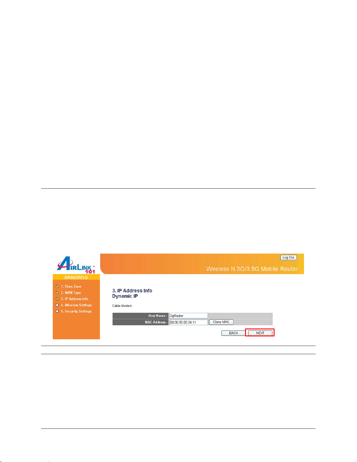
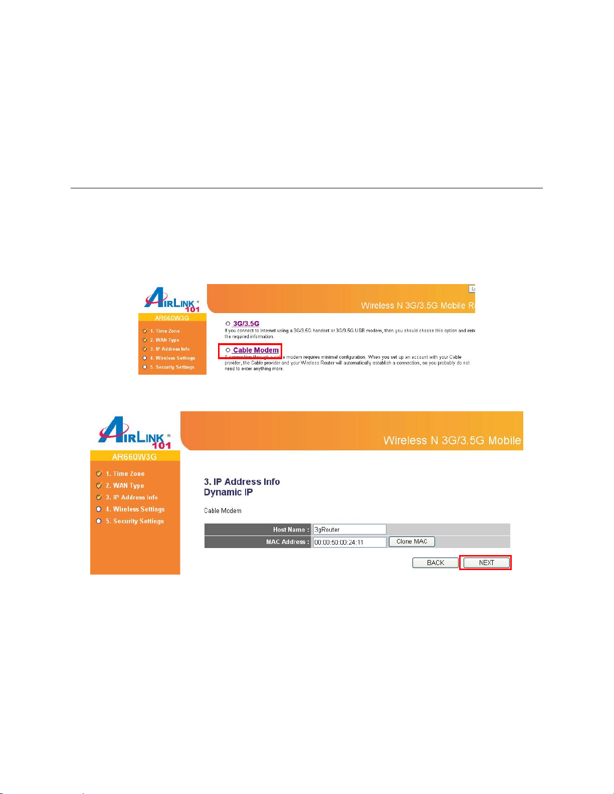
Cable
Click on Cable Modem if you are connecting to Internet through a cable modem.
When the Dynamic IP settings come up, click “Clone MAC” button and click NEXT.
Parameter Description
Host Name Please input the host name of your computer, this is optional,
and only required if your service provider asks you to do so.
MAC Address Please input MAC address of your computer here, if your service
provider only permits computer with certain MAC address to
access internet. If you are using the computer which used to
connect to Internet via cable modem, you can simply press
“Clone Mac address” button to fill the MAC address field with the
MAC address of your computer.
14
Page 14
DSL
For DSL users, your Internet type is either Dynamic IP or PPPoE. If you are not sure which one
you have, it is suggested to select PPPoE xDSL for your WAN type, and if you cannot connect
to the Internet after the Setup Wizard finished, go through the Setup Wizard again and select
Cable Modem. Otherwise, you can call your ISP to confirm which Internet type you have.
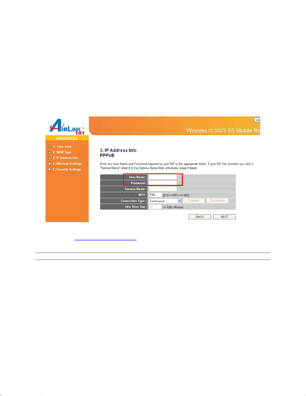
Option 1: PPPoE Settings
Click on PPPoE xDSL for your WAN type. Enter your user name and password provided by
your ISP. Click NEXT.
Note: Depending on the ISP, you may need to include the domain name with your username.
Example: username@sbcglobal.net
Parameter Description
User Name Please input user name assigned by your Internet service
provider here.
Password Please input the password assigned by your Internet service
provider here.
Service Name Please give a name to this Internet service (this is optional).
MTU Please input the MTU value of your network connection here. If
you don’t know, you can use default value.
Connection Type Please select the connection type you wish to use. There are 3
options:
1) ‘Continuous’ - keep internet connection alive, do not
disconnect,
15
Page 15
2) “Connect on Demand” - only connects to Internet when there’s
a connect attempt.
3) ‘Manual’ - only connects to Internet when ‘Connect’ button on
this page is pressed, and disconnects when ‘Disconnect button
is pressed.
Idle Time Out Specify the time to shutdown internet connect after no internet
activity is detected by minute. This option is only available when
connection type is ‘Connect on Demand’.
Option 2: Dynamic IP Settings
Click on Cable Modem for your WAN type.
When the Dynamic IP settings come up, leave the settings as default and click NEXT.
Fixed IP
Click on Fixed-IP xDSL if your ISP (Internet Service Provider) has provided you a set of IP
addresses for your Internet connection.
Enter the IP address, Subnet Mask and Default Gateway provided by your ISP.
Note: You must use the addresses provided by your Internet service provider, wrong setting
value will cause connection problem.
16
Page 16
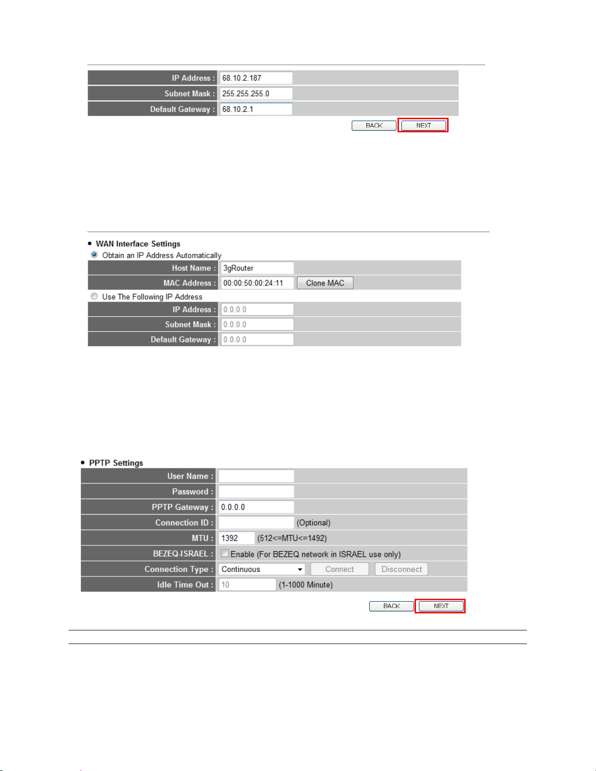
PPTP
PPTP xDSL requires two kinds of setting: WAN interface setting (setup IP address) and PPTP
setting (PPTP user name and password).
Here we start from WAN interface setting:
Select the type of how you obtain IP address from your service provider here. You can choose
“Obtain an IP address automatically” (equal to DHCP, please refer to „Cable Modem section
above), or “Use the following IP address” (i.e. static IP address).
WAN interface settings must be correctly set, or the Internet connection will fail even those
settings of PPTP settings are correct. Please contact your Internet service provider if you don’t
know what you should fill in these fields.
Now please go to PPTP settings section:
Parameter Description
User Name Please input user name assigned by your Internet service
provider here.
Password Please input the password assigned by your Internet service
provider here.
17
Page 17
PPTP Gateway Please input the IP address of PPTP gateway assigned by your
Internet service provider here.
Connection ID Please input the connection ID here, this is optional and
you can leave it blank.
MTU Please input the MTU value of your network connection here. If
you don’t know, you can use default value.
BEZEQ-ISRAEL Setting item BEZEQ-ISRAEL is only required to check if you’re
using the service provided by BEZEQ network in Israel.
Connection Type Please select the connection type of Internet connection you
wish to use, please refer to last section for detailed descriptions.
Idle Time Out Please input the idle time out of Internet connection you wish to
use, and refer to last section for detailed descriptions.
When you finish with all settings, please click NEXT.
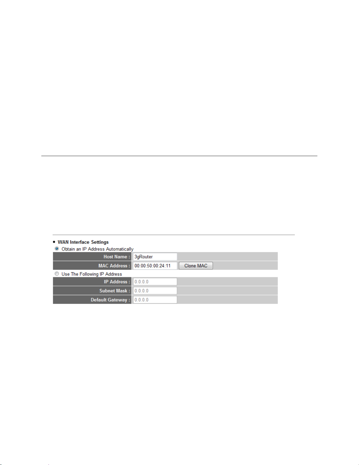
L2TP
L2TP is another connection method for xDSL and other Internet connection types, and all
required setting items are the same with PPTP connection. Like PPTP, there are two kinds of
required setting, we will start from “WAN Interface Settings”:
Select the type of how you obtain IP address from your service provider here. You can choose
“Obtain an IP address automatically” (equal to DHCP, please refer to „Cable Modem section
above), or “Use the following IP address” (i.e. static IP address).
WAN interface settings must be correctly set, or the Internet connection will fail even those
settings of L2TP settings are correct. Please contact your Internet service provider if you don’t
know what you should fill in these fields.
Now please go to L2TP settings section:
18
Page 18
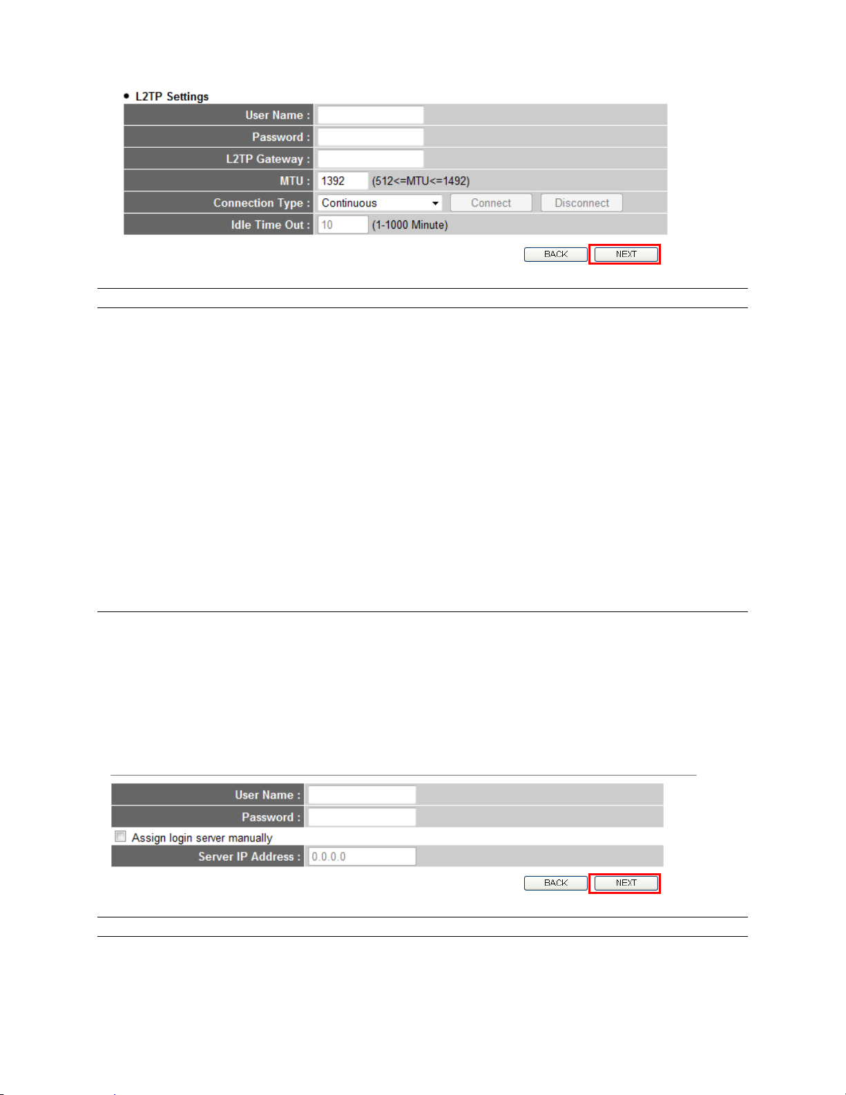
Parameter Description
User Name Please input user name assigned by your Internet service
provider here.
Password Please input the password assigned by your Internet service
provider here.
L2TP Gateway Please input the IP address of L2TP gateway
assigned by your Internet service provider here.
MTU Please input the MTU value of your network connection here. If
you don’t know, you can use default value.
Connection Type Please select the connection type of Internet connection you
wish to use, please refer to last section for detailed descriptions.
Idle Time Out Please input the idle time out of Internet connection you wish to
use, and refer to last section for detailed descriptions.
When you finish with all settings, please click NEXT.
Telstra Big Pond
This setting only works when you are using Telstra Big Pond’s network service in Australia. You
need to input:
Parameter Description
User Name Please input user name assigned by Telstra.
Password Please input the password assigned by Telstra.
19
Page 19
Assign login server manually Check this box to choose login server by yourself.
Server
IP Address Please input the IP address of login server here.
When you finish with all settings, please click NEXT.
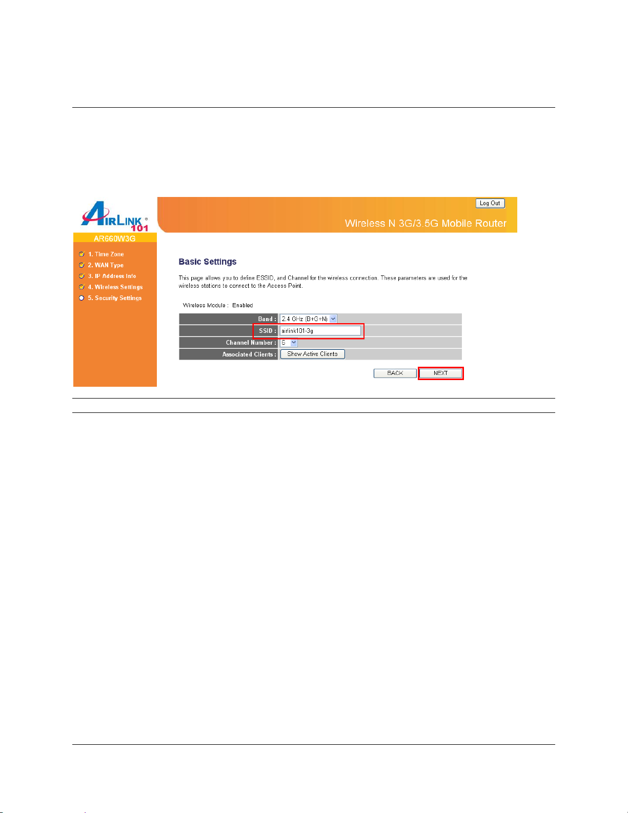
Step 6 Keep the default SSID (wireless network name) or change it to a desired name, so you
can always recognize your wireless network with it. Click Next.
Parameter Description
Band
Please select the radio band from one of the following options.
2.4GHz (B): 2.4GHz band, only allows 802.11b wireless network client
to connect to this router (maximum transfer rate 11Mbps).
2.4 GHz (N): 2.4GHz band, only allows 802.11n wireless network client
to connect to this router (maximum transfer rate 300Mbps).
2.4 GHz (B+G):2.4GHz band, only allows 802.11b and 802.11g wireless
network client to connect to this router (maximum transfer rate 11Mbps
for 802.11b clients, and maximum 54Mbps for 802.11g clients).
2.4 GHz (G): 2.4GHz band, only allows 802.11g wireless network client
to connect to this router (maximum transfer rate 54Mbps).
2.4 GHz (B+G+N): 2.4GHz band, allows 802.11b, 802.11g, and 802.11n
wireless network client to connect this router (maximum transfer rate
11Mbps for 802.11b clients, maximum 54Mbps for 802.11g clients, and
maximum 300Mbps for 802.11n clients).
SSID
This is the name of the wireless network. You can type any
alphanumerical characters here, maximum 32 characters. SSID is used
to identify your own wireless router from others when there are other
wireless routers in the same area. The default SSID is ‘airlink101’; it’s
recommended to change it to a name that you can identify, such as
myhome, office_room1, etc.
20
Page 20
Channel Number Select a channel from the dropdown list of ‘Channel Number’ for
broadcasting. You can choose any channel number you want to use, and
almost all wireless clients can locate the channel you’re using
automatically without any problem. However, it’s still useful to remember
the channel number you use, some wireless client supports manual
channel number selecting, and this would help in certain scenario when
there is some radio communication problem.
Associated Clients Click “Show Active Clients” button, then an “Active Wireless Client Table”
will pop up. You can see the status of all active wireless stations that are
connecting to the access point.
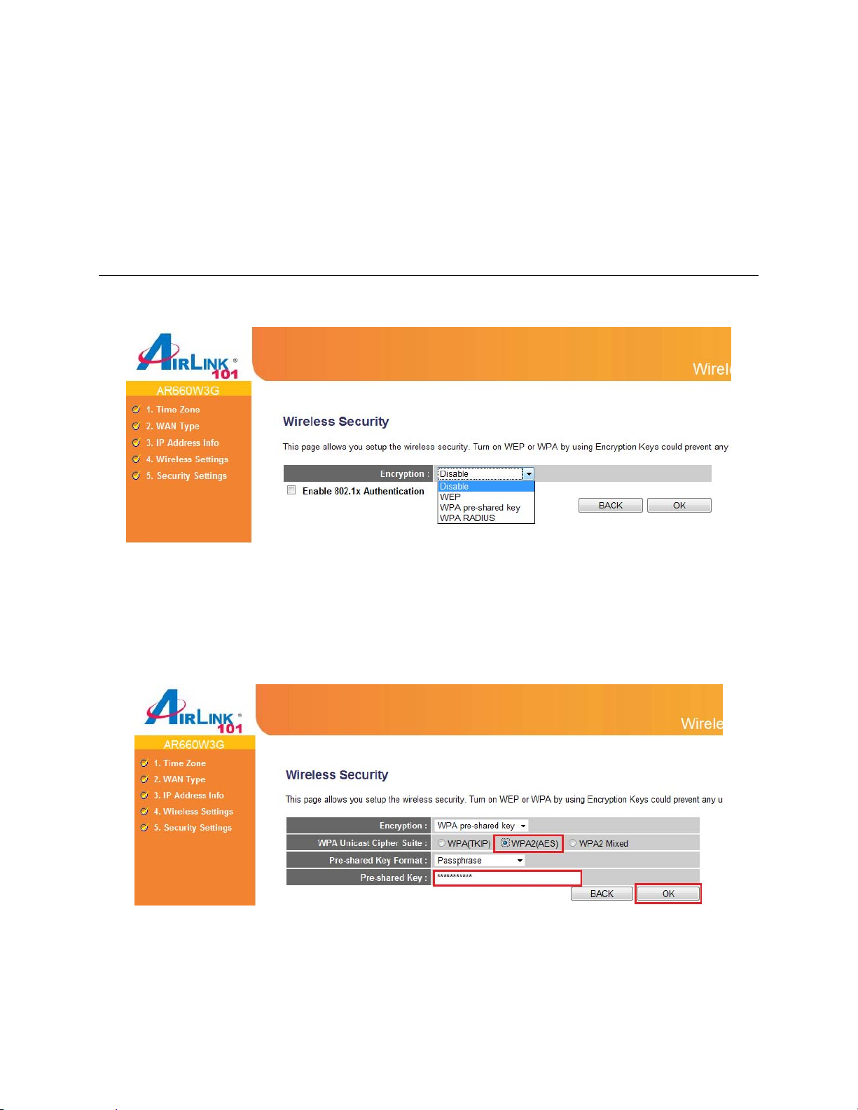
Step 7 Select a desired Security Mode from the drop-down menu.
WPA2(AES) is the most secured encryption mode for general users. WEP is the most common
encryption but the least secured. It is recommended to use WPA2 (AES) for your wireless
security if all wireless devices on your network can support this mode.
WPA2(AES)
Select WPA pre-shared key for Encryption.
Enter the settings below:
• WPA Unicast Cipher Suite: Select WPA2(AES)
• Pre-Shared Key Format: Select Passphrase
• Pre-shared Key: Enter a key between 8 to 63 characters (alphanumeric, case sensitive).
This is the security key for your wireless network
21
Page 21
Click OK to save the settings.
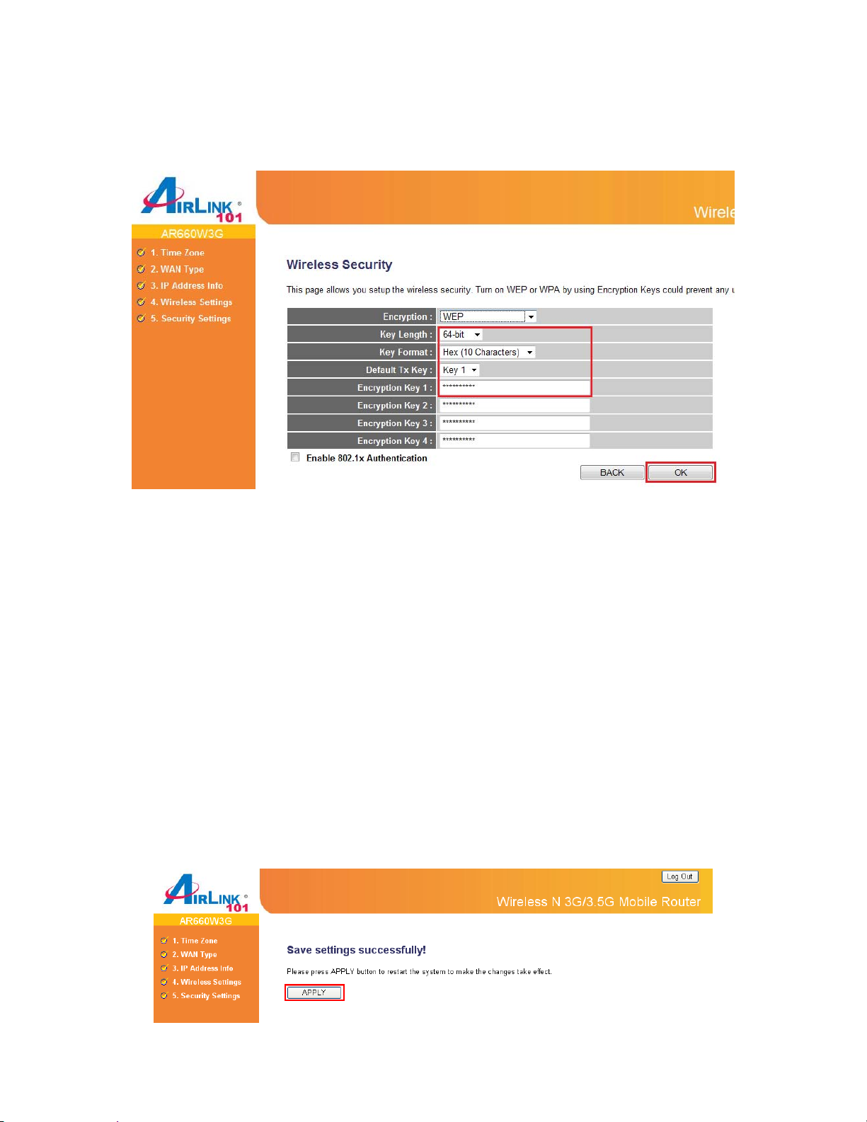
WEP
Enter the settings below:
• Key Length: Select 64-bit or 128-bit
• Key Format: Select ASCII or Hex
• Default Tx Key: Select Key 1
• Encryption Key 1: If you selected 64-bit key length and ASCII key format, enter 5
alphanumeric characters. If you selected 128-bit key length and ASCII key format, enter
13 alphanumeric characters. If you selected 64-bit key length and HEX key format, enter
10 hexadecimal characters (0~9, A~F) for Key Setting. If you selected 128-bit key length
and HEX key format, enter 26 hexadecimal characters. This is the security key for your
wireless network.
Click on OK to save and activate all the settings. Now, you can start to use the router as your
internet gateway.
Note: It is suggested to write down the security settings (Encryption and Key) you
configured for the Router on a piece of paper and keep it in a safe place.
Step 8 Click Apply to restart the router.
22
Page 22
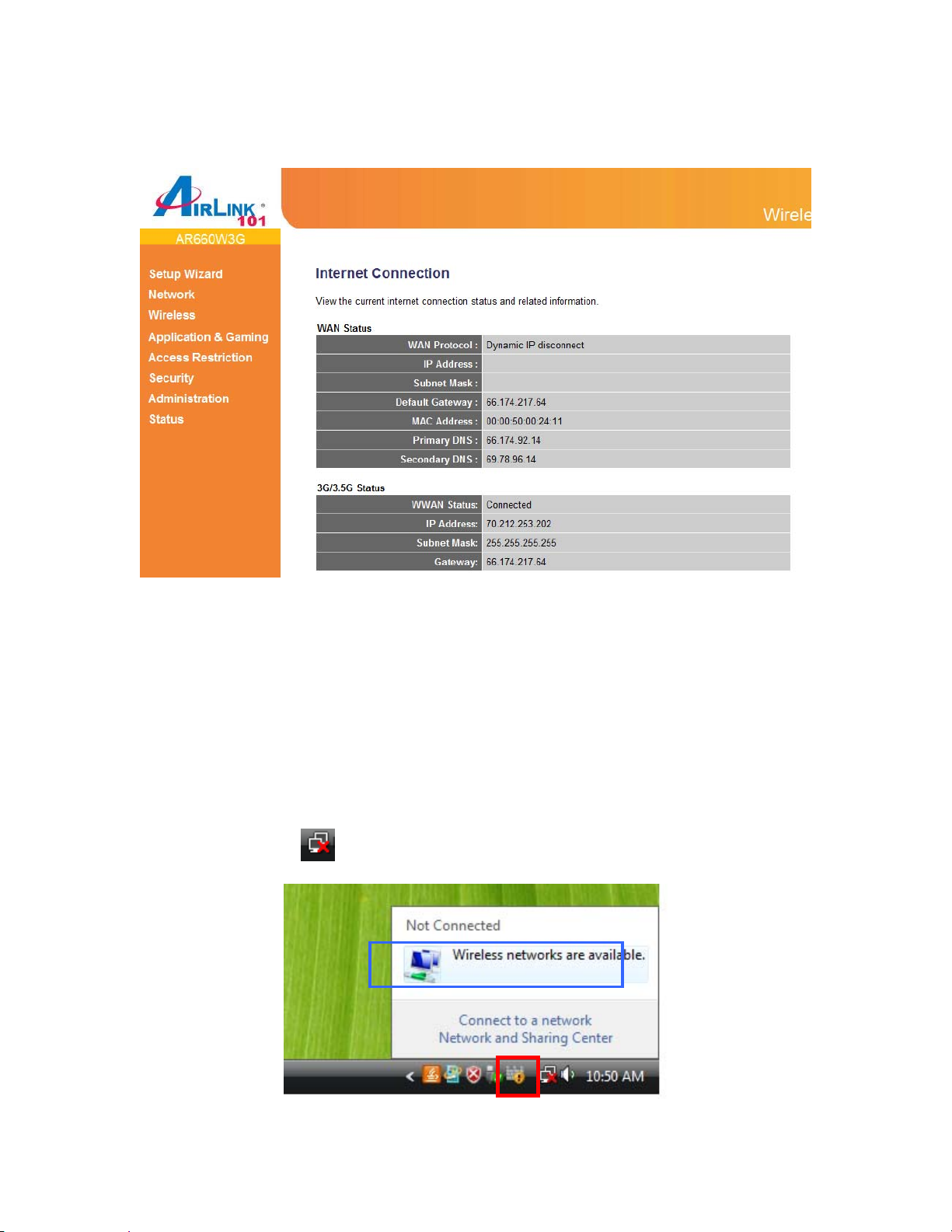
After 30 seconds, you will go back to the Status page with valid IP address assigned by you ISP
(or configured by yourself if you use Static IP) in either WAN or 3G/3.5G Status section. If either
section has valid IP addresses assigned, the router is connected to the Internet.
Congratulations! Your router configuration has been finished. You should now be able to
access the Internet; if not, please go to section 2.4 for troubleshooting.
2.3 Connecting to the Router Wirelessly
You must configure your wireless computer in order to establish a wireless connection to the
router. In this section, you can find the instructions of how to connect to the router wirelessly
with your Vista computer. You can also refer to the manual of your wireless network card
regarding how to connect to a router wirelessly.
Step 1 Click on this icon
are available.
on the task bar of your desktop, then click on Wireless networks
Step 2 Select the wireless network you want to connect to and click Connect.
23
Page 23
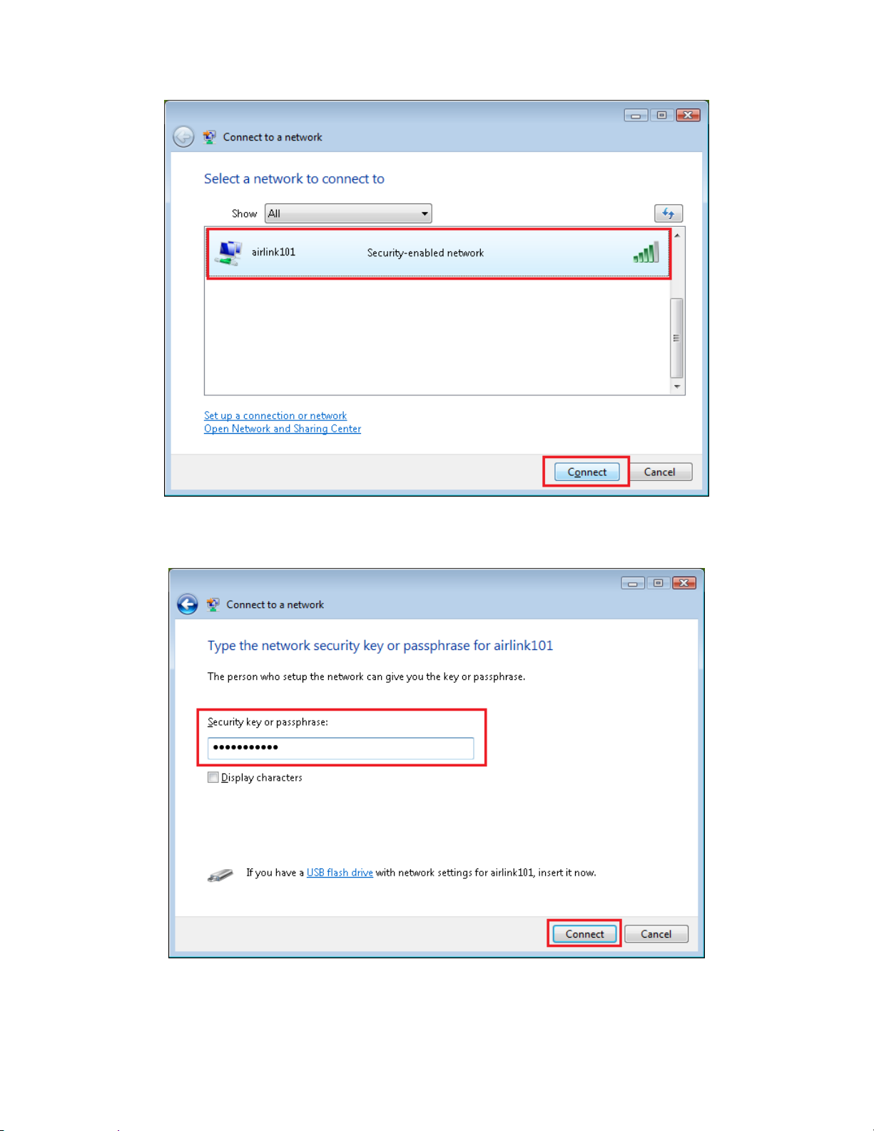
Step 3 Enter the Security key you configured for the Router (see Step 8 in Section 2). Click
Connect.
Step 4 Click on Close. Now the wireless connection has been established successfully with the
Router.
24
Page 24

25
Page 25

2.4 Troubleshooting
If you have trouble connecting to the Internet with Cable/DSL modem, try the following steps:
Step 1 Power off the Cable/DSL modem, router, and computer and wait for 5 minutes.
Step 2 Turn on the Cable/DSL modem and wait for the lights on the modem to settle down.
Step 3 Turn on the router and wait for the lights on the router to settle down.
Step 4 Turn on the computer.
Step 5 Log in to the router and you will see the Internet Connection Status.
Step 6 Verify that the Internet IP Address, Subnet Mask, and Default Gateway under WAN
Status section have valid numbers assigned to them (instead of all 0’s).
If you have trouble connecting to the Internet with 3G/3.5G USB modem, there are few things
your can try:
1. Make sure your 3G/3.5G modem is compatible with AR660W3G Wireless N 3G/3.5G Router.
Please check the compatibility list at www.airlink101.com
2. Make sure the 3G/3.5G USB modem works when it is directly connected to your computer
3. Make sure the 3G/3.5G USB modem is properly connected to the Router. The LED indicator
on the USB modem should be lit up.
4. Double check the 3G/3.5G modem settings you configured for the Router, and make sure all
settings are correct.
5. Verify that the Internet IP Address, Subnet Mask, and Default Gateway under 3G/3.5G
Status section have valid numbers assigned to them (instead of all 0’s).
26
.
Page 26

27
Page 27

Chapter 3 Using Web Configuration
Utility
The Web Configuration Utility contains advanced features that allow you to configure the router
to meet your network’s needs such as: Access Control, QoS (Quality of Service), Port
Forwarding (Virtual Server) and other functions. If you have already configured the Setup
Wizard, you do NOT need to configure any other thing here for you to start using the Internet.
Below is a general description of the advanced functions available for this router.
Menu Description
3.0 Setup Wizard This quick setup wizard can guide you through the basic settings
of this Router. Please see instructions in Chapter 2.2.
3.1 Network This section allows you to configure the Internet, 3G/3.5G settings
with your ISP, the settings of your local area network (LAN), such
as enable/disable the DHCP server, Dynamic DNS information,
and NAT function.
3.2 Wireless This section allows you to setup the Router’s SSID, security key,
WPS, etc.
3.3 Application & Gaming This section allows you to configure router’s setting for your
special applications or gaming requirements, such as open certain
ports for your applications.
3.4 Access Restrictions This section allows you to set up the access control rules, such as
MAC filtering, URL filtering to prevent the LAN users from
accessing certain type of website.
3.5 Security This Firewall section allows you to configure Hacker Prevention
and VPN pass through.
3.6 Administration The section allows you to specify a time zone, change the system
password, save/reload the router configuration, upgrade firmware
and so on.
3.7 Status You can see Router’s status in this section.
28
Page 28

3.1 Network
3.1.1 WAN
Use the WAN setting page to change your Internet connection type. The WAN setting page
allows you to configure the Internet connection type of your ISP. The WAN settings offer the
following selections for the router’s WAN port, Dynamic IP, Static IP, PPPoE, PPTP, L2TP and
Telstra Big Pond. Please choose one type and complete the detail settings below.
Please see Chapter 2.2, Step 5 for the detailed description of each WAN type.
3.1.2 3G/3.5G
Configure the 3G/3.5G settings if you like to connect to the Broadband Internet with your
3G/3.5G USB Modem.
29
Page 29

Note: The setting shown above is for Verizon 720 USB Modem.
Parameter Description
PIN Code Please input Pin Code for your UMTS or HSDPA or EVDO
connection, this is optional, and only required if your service
provider asks you to do so.
APN Please input the APN code assigned by your Internet service
provider here.
User Name Please input user name assigned by your Internet service
provider here.
Password Please input password assigned by your Internet service
provider here.
Verify Password Please input password again for confirmation.
Service Please select your service type between CDMA2000 or 3G/3.5G
Only. You may try both service types if you are not sure which
one your USB modem card uses.
AT Dial Script Please input Dialed Number for your UMTS or HSDPA
connection, the default is *99#. This field should not be altered
except when required by your service provider.
3.1.3 LAN
This page allows you to specify an IP address for your router, configure the DHCP Server and
Static DHCP Lease Table.
30
Page 30

¾ LAN IP section
Parameters Default Description
IP address 192.168.2.1 This is the router’s LAN IP address (Your LAN clients
default gateway IP address).
Subnet Mask 255.255.255.0 Specify a Subnet Mask for your LAN segment.
802.1d Spanning Tree Disable If you wish to activate 802.1d spanning tree function,
select “Enabled”, or set it to “Disabled”
If 802.1d Spanning Tree function is enabled, this router
will use the spanning tree protocol to prevent from
network loop happened in the LAN ports.
DHCP Server Enable By enablting the DHCP server, the router will
automatically give your LAN clients an IP address. If the
DHCP server is not enabled then you’ll have to manually
set your LAN client’s IP addresses; make sure the LAN
Client is in the same subnet as this broadband router if
you want the router to be your LAN client’s default
gateway.
¾ DHCP Server section
Parameters Description
Lease Time Please choose a lease time (the duration that every
computer can keep a specific IP address) of every IP
address assigned by this router from dropdown menu.
Start IP Please input the start IP address of the IP range.
End IP Please input the end IP address of the IP range. Domain
Name (4): If you wish, you can also optionally input the
domain name for your network. This is optional.
DHCP Client Range You can configure a particular IP address range for your
DHCP server to assign IP addresses to your LAN
Clients.
Note: By default the IP range is from: Start IP
192.168.2.100 to End IP 192.168.2.200. If you want your
PC to have a static/fixed IP address then you’ll have to
choose an IP address outside this IP address range.
Static DHCP Specify the Static DHCP Addresses for your LAN clients.
Domain Name Enter the domain name of your LAN interface if there is
one.
31
Page 31

¾ Static DHCP Lease Table section
This function allows you to assign a static IP address to a specific computer forever, so you
don’t have to set the IP address for a computer, and still enjoy the benefit of using DHCP
server. Maximum 16 static IP addresses can be assigned here. (If you set “Lease Time” to
forever in DHCP Server section, you can assign an IP address to a specific computer
permanently).
Parameters Description
Enable Static DHCP Leases Check this box to enable this function, otherwise DHCP
uncheck it to disable this function.
MAC Address Input the MAC address of the computer or network
device (total 12 characters, with character from 0 to 9,
and from a to f, like “00:11:22:aa:bb:cc”)
IP address Input the IP address you want to assign to this computer
or network device
Add After you entered MAC address and IP address pair,
click this button to add the pair to static DHCP leases
table.
After you clicked “Add”, the MAC address and IP address mapping will be added to “Static
DHCP Lease Table” section.
If you want to delete a specific item, please check the “Select” box of a MAC address and IP
address mapping, then click “Delete” button. If you want to delete all mappings, click “Delete
All”.
After you finish with all settings, please click “Apply” button.
If you want to reset all settings in this page, please click “Cancel” button.
32
Page 32

After you clicked Apply, the following message will be displayed on your web browser:
You can click “Continue” to back to previous setup page to continue on other setup procedures,
or click “Apply” to reboot the router so the settings will take effect (Please wait for about 30
seconds while router is rebooting).
3.1.4 DNS
If you select Dynamic IP or PPPoE as Internet connection method, at least one DNS server’s
IP address should be assigned automatically. However, if you have preferred DNS server, or
your service provider didn’t assign the IP address of DNS server because of any reason, you
can input the IP address of DNS server here.
Parameter Description
Primary DNS Please input the IP address of DNS server provided by your
service provider.
Secondary DNS Please input the IP address of another DNS server provided by
your service provider, this is optional.
After you finish with all settings, please click “Apply” button.
If you want to reset all settings in this page, please click “Cancel” button.
After you clicked Apply, the following message will be displayed on your web browser:
33
Page 33

You can click “Continue” to back to previous setup page to continue on other setup procedures,
or click “Apply” to reboot the router so the settings will take effect (Please wait for about 30
seconds while router is rebooting).
3.1.5 DDNS
DDNS allows you to map the static domain name to a dynamic IP address. You must get an
account, password and a static domain name from a DDNS service provider. This router
supports DynDNS (www.dyndns.org
), and TZO (www.tzo.com).
Parameters Default Description
Dynamic DNS Disable Enable/Disable the DDNS function of this router.
Provider Select a DDNS service provider.
Domain name Your static domain name that use DDNS.
Account The account/username that your DDNS service provider
assigned to you.
Password/Key The password you set for the DDNS service account
above.
After you finish with all settings, please click “Apply” button.
If you want to reset all settings in this page, please click “Cancel” button.
34
Page 34

After you clicked Apply, the following message will be displayed on your web browser:
You can click “Continue” to back to previous setup page to continue on other setup procedures,
or click “Apply” to reboot the router so the settings will take effect (Please wait for about 30
seconds while router is rebooting).
3.1.6 NAT
Network address translations solve the problem if sharing a single IP address to multiple
computers. Without NAT, all computers must be assigned with a valid public IP address to get
connected to Internet, but Internet service providers only provide very few IP addresses to every
user. Therefore it’s necessary to use NAT technology to share a single Internet IP address to
multiple computers on local network, so everyone can get connected to Internet.
Please follow the following instructions to set NAT parameters:
The NAT function is enabled by default; to disable, please select “Disable”. Do not disable NAT
unless you have professional knowledge on routing.
After you finish with all settings, please click “Apply” button.
If you want to reset all settings in this page, please click “Cancel” button.
After you clicked Apply, the following message will be displayed on your web browser:
35
Page 35

You can click “Continue” to back to previous setup page to continue on other setup procedures,
or click “Apply” to reboot the router so the settings will take effect (Please wait for about 30
seconds while router is rebooting).
3.2 Wireless
3.2.1 Basic Settings
You can set parameters that are used for wireless clients to connect to this router. The
parameters include SSID, Channel Number, etc.
Parameters Default Description
Band 2.4 GHz (B+G+N) Please select the radio band from one of the following
options.
2.4GHz(B): 2.4GHz band, only allows 802.11b wireless
network client to connect this router (maximum transfer
rate 11Mbps*).
2.4 GHz (N): 2.4GHz band, only allows 802.11n wireless
network client to connect this router (maximum transfer
rate 300Mbps*).
2.4 GHz (B+G):2.4GHz band, only allows 802.11b and
802.11g wireless network client to connect this router
(maximum transfer rate 11Mbps for 802.11b clients, and
maximum 54Mbps for 802.11g clients*).
2.4 GHz (G): 2.4GHz band, only allows 802.11g wireless
network client to connect this router (maximum transfer
rate 54Mbps*).
2.4 GHz (B+G+N): 2.4GHz band, allows 802.11b,
802.11g, and 802.11n wireless network client to connect
this router (maximum transfer rate 11Mbps for 802.11b
36
Page 36

clients, maximum 54Mbps for 802.11g clients, and
maximum 300Mbps for 802.11n clients*).
SSID airlink101 This is the name of your wireless network. You can type
any alphanumerical characters here, maximum 32
characters. SSID is used to identify your own wireless
router from others when there are other wireless routers
in the same area. It’s recommended to change default
SSID value to the one which is meaningful to you, like
myhome, office_room1, etc.
Channel
Show
Number 6 Please select a channel from the dropdown list of
‘Channel Number’ for broadcasting. You can choose any
channel number you want to use, and almost all wireless
clients can locate the channel you’re using automatically
without any problem. However, it’s still useful to
remember the channel number you use, some wireless
client supports manual channel number select, and this
would help in certain scenario when there is some radio
communication problem.
Active Clients Click “Show Active Clients” button, then an “Active
Wireless Client Table” will pop up. You can see the
status of all active wireless clients that are connecting to
the Router.
After you finish with all settings, please click “Apply” button.
If you want to reset all settings in this page, please click “Cancel” button.
After you clicked Apply, the following message will be displayed on your web browser:
You can click “Continue” to back to previous setup page to continue on other setup procedures,
or click “Apply” to reboot the router so the settings will take effect (Please wait for about 30
seconds while router is rebooting).
3.2.2 Wireless Security
The AR660W3G provides complete wireless LAN security functions, including WEP,
IEEE 802.11x, WPA2/WPA-PSK and WPA with RADIUS. With these security functions,
you can prevent your wireless LAN from illegal access. Please make sure your wireless
clients use the same security settings.
37
Page 37

Parameters Default Description
Encryption You can choose Disable, WEP, WPA pre-share key,
WPA RADIUS for encryption mode.
Enable 802.1x Authentication IEEE 802.1x is an authentication protocol. Every user
must use a valid account to login to this Access Point
before accessing the wireless LAN. The authentication is
processed by a RADIUS server. Check this box to
authenticates user by IEEE 802.1x.
After you finish with all security settings, please click “Apply” button.
If you want to reset all settings in this page, please click “Cancel” button.
After you clicked Apply, the following message will be displayed on your web browser:
You can click “Continue” to back to previous setup page to continue on other setup procedures,
or click “Apply” to reboot the router so the settings will take effect (Please wait for about 30
seconds while router is rebooting).
3.2.2.1 WEP
Select “WEP” for the “Encryption” mode if you wish to use WEP to encrypt your wireless
network.
38
Page 38

Parameters Description
Key Length You can select the WEP key length for encryption, 64-bit or 128-
bit. Larger WEP key length will provide higher level of security,
but the throughput will be lower.
Key Format You may select to select ASCII Characters (alphanumeric
format) or Hexadecimal Digits (in the “A-F”, “a-f” and “0-9” range)
to be the WEP Key.
Default Tx Key You can set up to four sets of WEP key, and you can decide
which key is being used by default here. If you don’t know which
one you should use, select ‘Key 1’.
Encryption Key 1~4 The WEP key are used to encrypt data transmitted in the
wireless network. Fill the text box by following the rules below.
64-bit WEP: input 10-digit Hex values (in the “A-F”, “a-f” and “09” range) or 5-digit ASCII character as the encryption keys.
128-bit WEP: input 26-digit Hex values (in the “A-F”, “a-f” and “09” range) or 13-digit ASCII characters as the encryption keys.
3.2.2.2 WPA Pre-share Key
Wi-Fi Protected Access (WPA) is an advanced security standard. You can use a pre-shared key
to authenticate wireless stations and encrypt data during communication. It uses TKIP/AES to
change the encryption key frequently. So the encryption key is not easy to be broken by
hackers. This can improve security very much.
Select “WPA Pre-share Key” for the “Encryption” mode if you wish to use WPA/WPA2-PSK to
encrypt your wireless network.
39
Page 39

Parameters Description
WPA Unicast Cipher Suite Available options are: WPA (TKIP), WPA2 (AES), and WPA2
Mixed. You can select one of them, but you have to make sure
your wireless client supports the cipher you selected.
Pre-shared Key Format You may select Passphrase (alphanumeric format) or Hex (in the
“A-F”, “a-f” and “0-9” range) to be the Pre-shared Key.
Pre-shared Key The Pre-shared key is used to authenticate and encrypt data
transmitted in the wireless network. You may create your own
key here for wireless clients to connect to your router.
3.2.2.3 WPA RADIUS
IEEE 802.1x is an authentication protocol. Every user must use a valid account to login to this
wireless router before accessing the wireless LAN. The authentication is processed by a
RADIUS server. This mode only authenticates user by IEEE 802.1x, but it does not encryption
the data during communication.
Select “WPA RADIUS” for the “Encryption” mode if you wish to use WPA RADIUS to encrypt
your wireless network.
40
Page 40

Parameters Description
WPA Unicast Cipher Suite Please select a type of WPA cipher suite.
Available options are: WPA (TKIP), WPA2 (AES), and WPA2
Mixed. You can select one of them, but you have to make sure
your wireless client support the cipher you selected.
RADIUS Server IP Address Please input the IP address of your Radius authentication server
here.
RADIUS Server Port Please input the port number of your Ra dius authentication
server here. Default setting is 1812.
RADIUS Server Password Please input the password of your Radius authentication server
here.
3.2.3 MAC Control
This function will help you to prevent unauthorized users from connecting to your wireless
router. Only those wireless devices with the MAC addresses you specified here are allowed to
access your wireless router. You can use this function with other security measures described in
previous section together.
Up to 20 MAC addresses can be added by using this function.
41
Page 41

Parameters Description
Delete If you want to delete a specific MAC address entry,
check the ‘select’ box of the MAC address you want to
delete, then click ‘Delete’ button. (You can select more
than one MAC addresses).
Delete All If you want to delete all MAC addresses listed here,
please click ‘Delete All’ button.
Enable MAC Control
MAC Address
Comment
Add Click “Add” button to add the MAC address and
Clear Click “Clear” to remove the value you inputted in MAC
Reset You can also click ‘Reset’ button to unselect all.
Input the MAC address of your wireless devices here,
You can input any text here as the comment of this MAC
Check/Uncheck to enable/disable wireless MAC control.
format ‘xx:xx:xx:xx:xx:xx’.
address, like ‘ROOM 2A Computer’ or anything.
associated comment to the MAC address filtering table.
address and comment field.
After you finish with all settings, please click “Apply” button.
If you want to reset all settings in this page, please click “Cancel” button.
After you clicked Apply, the following message will be displayed on your web browser:
You can click “Continue” to back to previous setup page to continue on other setup procedures,
or click “Apply” to reboot the router so the settings will take effect (Please wait for about 30
seconds while router is rebooting).
3.2.4 Advanced Settings
You can set advanced wireless LAN parameters of this router. The parameters include
Authentication Type, Fragment Threshold, RTS Threshold, Beacon Interval, Preamble Type, etc.
It is suggested not to change these parameters unless you know what effect the changes will
have on this router.
42
Page 42

Parameters Description
Fragment Threshold
“Fragment Threshold” specifies the maximum size of packet
during the fragmentation of data to be transmitted. The default
value is 2346.
RTS Threshold When the packet size is smaller than the RTS threshold, the
wireless router will not use the RTS/CTS mechanism to send this
packet.
Beacon Interval
The interval of time that this wireless router broadcast a beacon.
Beacon is used to synchronize the wireless network.
DTIM Period Set the DTIM period of wireless radio. Do not modify default
value if you don’t know what it is, default value is 3.
Data Rate Set the wireless data transfer rate to a certain value. Since most
of wireless devices will negotiate with each other and pick a
proper data transfer rate automatically, it’s not necessary to
change this value unless you know what will happen after
modification.
N Data Rate Same as above, but only for 802.11n clients.
Channel Width Set channel width of wireless radio. Do not modify default value
if you don’t know what it is, default setting is ‘Auto 20/40 MHz’.
Preamble Type
The “Long Preamble” can provide better wireless LAN
compatibility while the “Short Preamble” can provide better
wireless LAN performance.
43
Page 43

Broadcast ESSID Decide if the wireless router will broadcast its own ESSID or not.
You can hide the ESSID of your wireless router by selecting
“Disable”
CTS Protect
Tx Power You can set the output power of wireless radio. Unless you are
WMM The short of Wi-Fi MultiMedia, it will enhance the data transfer
It is recommended to enable the protection mechanism. This
mechanism can decrease the rate of data collision between
802.11b and 802.11g/802.11n wireless stations. When the
protection mode is enabled, the throughput of the AP will be a
little lower due to many of frame traffic should be transmitted.
using this wireless router in a really big space, you may not have
to set output power to 100%. This will enhance security
(malicious / unknown users in distance will not be able to reach
your wireless router).
performance of multimedia contents when they are being
transferred over wireless network. The default value is “Disable”.
After you finish with all settings, please click “Apply” button.
If you want to reset all settings in this page, please click “Cancel” button.
After you clicked Apply, the following message will be displayed on your web browser:
You can click “Continue” to back to previous setup page to continue on other setup procedures,
or click “Apply” to reboot the router so the settings will take effect (Please wait for about 30
seconds while router is rebooting).
3.2.5 WPS
The AR660W3G Airlink101 Wireless N 3G/3.5G Mobile Router has a Easy Setup Button built-in
which allows you to connect your wireless computer with the router easily and safely. Your
wireless adapter must support this feature as well. If not, you will need to set up the wireless
security manually and you can skip this section.
44
Page 44

Please make sure this feature is enabled on the Router (see the screenshot above). In the
instructions below, we are going to use the Airlink101 WLAN Monitor utility comes with the
AWLL6077v2 Airlink101 Golden 300N Wireless USB Adapter as an example.
Step 1 Go to the computer with Airlink101 Wireless N adapter, AWLL6077v2 connected.
Step 2 Push and hold the Easy Setup Button on the Adapter until you see the following window
pops up on the computer monitor.
Step 3 Within the following 2 minutes, push the Easy Setup Button the Router. The WLAN LED
will stay solid green instead of blinking.
45
Page 45

Step 4 The Router will now start the handshake with the wireless adapter which will take about
30 seconds. When you see the window similar to the one below, the connection has been
established.
Parameters Description
Enable WPS Check this box to enable WPS function, uncheck it to disable
WPS.
Wi-Fi Protected Setup Information WPS-related system information will be displayed here:
WPS Status: If the wireless security (encryption) function of this
wireless router is properly set, you’ll see “Configured” message
46
Page 46

here. If wireless security function has not been set, you’ll see
“unConfigured”.
Self PIN code: This is the WPS PIN code of this wireless router.
This code is useful when you need to build wireless connection
by WPS with other WPS-enabled wireless devices.
SSID: The SSID of this wireless router will be displayed here.
Authentication Mode: The wireless security authentication mode
of this wireless router will be displayed here. If you dont enable
security function of the wireless router before WPS is activated,
the router will auto set the security to WPA (AES) and generate a
set of passphrase key for WPS connection.
Passphrase Key: The wireless security key of the router will be
displayed here.
Config Mode There are “Registrar” and “Enrollee” modes for the WPS
connection. When “Registrar” is enabled, the wireless clients will
follow the router’s wireless settings for WPS connection. When
“Enrollee” mode is enabled, the router will follow the wireless
settings of wireless client for WPS connection.
Configure by Push Button Click “Start PBC” to start Push-Button style WPS setup
procedure. This wireless router will wait for WPS requests from
wireless clients for 2 minutes. The “WLAN” LED on the wireless
router will be steady on for 2 minutes when this wireless router is
waiting for incoming WPS request.
Configure by Pin Code Please input the PIN code of the wireless client you wish to
connect, and click “Start PIN” button. The “WLAN” LED on the
wireless router will be steady on when this wireless router is
waiting for incoming WPS request.
47
Page 47

3.3 Application & Gaming
3.3.1 Port Forwarding
The Port Forwarding allows you to re-direct a particular range of service port numbers (from the
Internet/WAN Ports) to a particular LAN IP address. It helps you to host some servers behind
the router NAT firewall.
Parameter Description
Enable Port Forwarding Enable Port Forwarding
Private IP This is the private IP address of the server behind the NAT
firewall. Note: You need to give your LAN PC clients a
fixed/static IP address for Port Forwarding to work properly.
Computer Name Pull down the menu and all the computers connected to the
router will be listed here. If you do not see any computer after
you click on the drop-down menu, select the option “Refresh”
and you will be given a list of computers that are connected to
your network. You can easily select the computer name without
checking the IP address of the computer.
Type This is the protocol type to be forwarded. You can choose to
forward “TCP” or “UDP” packets only or select “both” to forward
both “TCP” and “UDP” packets.
Port Range The range of ports to be forward to the private IP.
Comment The description of this setting.
Current Port Forwarding Table From the table, you can check each Port forwarding setting.
48
Page 48

Delete Selected If you want to delete a setting, check the ‘select’ box of the
setting you want to delete, then click ‘Delete Selected’ button.
(You can select more than one setting).
Delete All If you want to delete all settings listed here, please click ‘Delete
All’ button.
Reset You can also click ‘Reset’ button to unselect all.
After you finish with all settings, please click “Apply” button.
If you want to reset all settings in this page, please click “Cancel” button.
After you clicked Apply, the following message will be displayed on your web browser:
You can click “Continue” to back to previous setup page to continue on other setup procedures,
or click “Apply” to reboot the router so the settings will take effect (Please wait for about 30
seconds while router is rebooting).
3.3.2 Port Triggering
Some applications require multiple connections, such as Internet gaming, video conferencing,
Internet telephony and others. These applications cannot work when Network Address
Translation (NAT) is enabled. If you need to run applications that require multiple connections,
specify the port normally associated with an application in the “Trigger Port” field, select the
protocol type as TCP or UDP, then enter the public ports associated with the trigger port to open
them for inbound traffic. Note: The range of the Trigger port is 1 to 65535.
49
Page 49

Parameter Description
Enable Port Triggering Check to enable Port Trig gering, or uncheck to disable.
IP Address This is the private IP of the computer/server behind the NAT
firewall. Note: You need to give your PC a fixed/static IP
address for Port Triggering to work properly.
Computer Name This is the computer that you need to enable the port triggering
function. Select a PC from here if you do not know its IP
address and click on the << button to add the IP address to the
left blank. If you do not see any computer after you click on the
drop-down menu, select the option “Refresh” and you will be
given a list of computers that are connected to your network.
TCP/UDP Port to Open
This is the TCP/UDP ports you want to trigger. Type in a range
of TCP/UDP ports to be triggered. For instance, “5000-5300” or
“9091, 9093-9100”, depending on your special application’s
requirement.
Comment The description of this setting.
Popular Application This list includes many popular applications you may be using.
Select the application you want to use and click on the Add
button next to it; you will see the proper port numbers added to
the “TCP/UDP Port to Open” blank.
Add (in red box)
Click on Add button in the red box to save the trigger rule you
set into the Trigger-Port Table.
Current Trigger-Port Table From the table, you can select each Port triggering setting by
checking the “Select” checkbox.
50
Page 50

Delete Selected If you want to delete a setting, check the ‘select’ box of the
setting you want to delete, then click ‘Delete Selected’ button.
(You can select more than one setting).
Delete
Reset
All If you want to delete all settings listed here, please click ‘Delete
All’ button.
You can also click ‘Reset’ button to unselect all.
After you finish with all settings, please click “Apply” button.
If you want to reset all settings in this page, please click “Cancel” button.
After you clicked Apply, the following message will be displayed on your web browser:
You can click “Continue” to back to previous setup page to continue on other setup procedures,
or click “Apply” to reboot the router so the settings will take effect (Please wait for about 30
seconds while router is rebooting).
3.3.3 DMZ
If you have a local client PC that cannot run an Internet application (e.g. Games) properly from
behind the NAT firewall, then you can open the client up to unrestricted two-way Internet access
by defining a DMZ Host. The DMZ function allows you to re-direct all packets going to your
WAN port IP address to a particular IP address in your LAN.
51
Page 51

Parameters Description
Enable DMZ Check/uncheck to enable/disable DMZ.
Public IP You can select “Dynamic IP” or “Static IP” here. If you select “Dynamic
IP”, you have to select an Internet connection session from drop down
menu; if you select “Static IP”, please input the IP address that you want
to map to a specific private IP address.
Client PC IP address Please input the private IP address that the Internet IP address will be
mapped to.
Computer Name Pull down the menu and all the computers connected to the router will be
listed here. You can easily to select the computer name without checking
the IP address of the computer. If you do not see any computer after you
click on the drop-down menu, select the option “Refresh” and you will be
given a list of computers that are connected to your network.
Add Click “Add” button to add the public IP address and a ssoci ated private IP
address to the DMZ table.
Reset Click “Reset” to remove the value you inputted in Public IP address and
Client PC IP address field.
Current DMZ table All existing public IP address and private IP address mappin g will be
displayed here.
Delete If you want to delete a specific DMZ entry, check the “Select”‟ box of the
DMZ entry you want to delete, then click “Delete”‟ button. (You can
select more than one DMZ entries).
Delete All If you want to delete all DMZ entries listed here, please click “Delete All‟”
button.
52
Page 52

Reset You can also click “Reset”‟ button to unselect all DMZ entries.
After you finish with all settings, please click “Apply” button.
If you want to reset all settings in this page, please click “Cancel” button.
After you clicked Apply, the following message will be displayed on your web browser:
You can click “Continue” to back to previous setup page to continue on other setup procedures,
or click “Apply” to reboot the router so the settings will take effect (Please wait for about 30
seconds while router is rebooting).
3.3.4 ALG Settings
Application Layer Gateway (ALG) is a special function of this router. It includes many preset
routing rules for numerous applications which require special support. With these supports,
those applications which required special support will be able to work with NAT architecture.
There are many applications listed here. Please check the box of the special support for
applications you need.
After you finish with all settings, please click “Apply” button.
53
Page 53

If you want to reset all settings in this page, please click “Cancel” button.
After you clicked Apply, the following message will be displayed on your web browser:
You can click “Continue” to back to previous setup page to continue on other setup procedures,
or click “Apply” to reboot the router so the settings will take effect (Please wait for about 30
seconds while router is rebooting).
3.3.5 QoS
Quality of service provides an efficient way for computers on the network to share the internet
bandwidth with a promised quality of internet service. Without QoS, all computers and devices
on the network will compete with each other to get internet bandwidth, and some applications
which require guaranteed bandwidth (like video streaming and network telephone) will be
affected, therefore an unpleasing result will occur, like the interruption of video / audio transfer.
With this function, you can limit the maximum bandwidth or give a guaranteed bandwidth for a
specific computer, to avoid said unpleasing result from happening.
Parameter Description
54
Page 54

Enable QoS Check this box to enable QoS, and uncheck this box to disable
QoS.
Total Download Bandwidth You can set the limit of total download bandwidth in kbits. To
disable download bandwidth limitation, input 0 here.
Total Upload Bandwidth You can set the limit of total upload bandwidth in kbits. To
disable upload bandwidth limitation, input 0 here.
Current
Add Click “Add” b utton to add a new QoS rule, see section 3.3.5.1
Edit If you want to modify the content of a specific rule, please check
Delete
Delete
Move Up You can raise the priority of the QoS rule you selected by
Move Down You can lower the priority of the QoS rule you selected by
QoS Table From the table, you can check each QoS rule setting.
“Add a new QoS rule”‟ below.
its “Select”‟ box, then click “Edit” button. Only one rule should
be selected a time! If you didn’t select a rule before clicking
“Edit” button, you’ll be prompted to add a new rule.
Selected If you want to delete a setting, check the ‘select’ box of the
setting you want to delete, then click ‘Delete Selected’ button.
(You can select more than one setting).
All If you want to delete all settings listed here, please click ‘Delete
All’ button.
clicking this button.
clicking this button.
3.3.5.1 Add a new QoS rule
After you click “Add” button in QoS menu, the following message will appear:
55
Page 55

Parameter Description
Rule Name Please give a name to this QoS rule (up to 15 alphanumerical
characters).
Bandwidth Set the bandwidth limitation of this QoS rule. You have to select
the data direction of this rule (Upload of Download), and the
speed of bandwidth limitation in Kbps, then select the type of
QoS: “guarantee”‟ (guaranteed usable bandwidth for this rule) or
“max” (set the maximum bandwidth for the application allowed by
this rule).
Local IP Address Specify the local (source) IP address that will be affected by this
rule. Please input the starting IP address in the left field, and
input the end IP address in the right field to define a range of IP
addresses, or just input the IP address in the left field to define a
single IP address.
Local Port Range Please input the range of local (source) port numbers that will be
affected by this rule. If you want to apply this rule on port 80 to
90, please input ‟80-90‟; if you want to apply this rule on a single
port, just input the port number, such as 80.
Remote IP Address Specify the remote (destination) IP address that will be affected
by this rule. Please input the starting IP address in the left field,
and input the end IP address in the right field to define a range of
IP addresses, or just input the IP address in the left field to
define a single IP address.
Remote Port Range Please input the range of remote (destination) port number that
will be affected by this rule. If you want to apply this rule on port
80 to 90, please input ‟80-90‟; if you want to apply this rule on a
single port, just input the port number, such as 80‟. If the remote
56
Page 56

(destination) IP address and /or port number is universal, just
leave it blank.
Traffic Type Please select the traffic type of this rule, available options are
None, SMTP, HTTP, POP3, and FTP. You can select a specific
traffic type for this rule, if you want to make this rule as a IP
address based rule (apply the limitation on all traffics from / to
the specified IP address / port number), select “None”.
Protocol Please select the protocol type of this rule, available options are
TCP and UDP. If you don‟t know what protocol your application
uses, please try “TCP” first, and switch to “UDP” if this rule
doesn’t seems to work.
After you finish with all settings, please click “Save” button, you’ll be brought back to previous
menu, and the rule you just set will appear in current QoS table; if you did anything wrong, you’ll
get an error message when you click “Save” button, please correct your input by the instructions
given by the error message.
After you finish with all QoS settings, please click “Apply” button.
If you want to reset all settings in this page, please click “Cancel” button.
After you clicked Apply, the following message will be displayed on your web browser:
You can click “Continue” to back to previous setup page to continue on other setup procedures,
or click “Apply” to reboot the router so the settings will take effect (Please wait for about 30
seconds while router is rebooting).
57
Page 57

3.4 Access Restrictions
This function allows you to configure some Internet access rules for your local computers based
on the IP address, applications, URL or keywords.
3.4.1 Access Control
This function allows or denies computers with specific MAC address from connecting to the
network; it can also allow or deny computers with specific IP address, protocol, or port.
58
Page 58

3.4.1.1 MAC Filtering
If you want to restrict users from accessing certain Internet applications/services (e.g. Internet
websites, email, FTP etc.) by their MAC addresses, then you can set up the filtering rules here.
Parameters Description
Enable MAC Filtering Check this box to enable the MAC filtering function. Please
select “Deny” or “Allow” to decide the behavior of MAC filtering
table. If you select Deny, all MAC addresses listed in filtering
table will be denied from connecting to the network; if you select
Allow, only MAC addresses listed in filtering table will be able to
connect to the network, and all other network devices are
rejected.
Client PC MAC Address
Computer Name Pull down the menu and all the computers connected to the
Input the MAC address of the devices you want to filter, format
‘xx:xx:xx:xx:xx:xx’.
router will be listed here. You can easily to select the computer
name without checking the IP address of the computer. If you do
not see any computer after you click on the drop-down menu,
select the option “Refresh” and you will be given a list of
computers that are connected to your network
59
Page 59

Comment You can input any text here as the comment of this MAC
address, like ‘ROOM 2A Computer’.
Add Click “Add” button to add the MAC address and associated
comment to the MAC address filtering table.
Reset Remove all inputted values.
Current
Delete Selected
Delete All
Reset
MAC Filtering Table From the table, you can check each MAC Address filter setting.
If you want to delete a specific MAC address entry, check the
‘select’ box of the MAC address you want to delete, then click
‘Delete’ button. (You can select more than one MAC addresses).
If you want to delete all MAC addresses listed here, please click
‘Delete All’ button.
You can also click ‘Reset’ button to unselect all.
3.4.1.2 IP Filtering
If you want to restrict users from accessing certain Internet applications/services (e.g. Internet websites,
email, FTP etc.) by their IP addresses, then you can set up the filtering rules here. Entries in this table are
restricted to use certain type of connections from the router. IP filters can be helpful in securing or
restricting your local network.
Parameters Description
Enable IP Filtering Please select “Deny” or “Allow” to decide the behavior of IP
filtering table. If you select deny, all IP addresses listed in
filtering table will be denied from connecting to the network; if
you select allow, only IP addresses listed in filtering table will be
able to connect to the network, and rejecting all other network
devices.
Add PC Click “Add PC” to add a new IP address to IP filtering table. See
more information below.
Delete If you want to delete a specific setting, check the ‘select’ box of
the setting you want to delete, then click ‘Delete Selected’ button.
(You can select more than one setting).
Delete All If you want to delete all settings listed here, please click ‘Delete
All’ button.
60
Page 60

Click Add PC to add a new IP address to IP filtering table, up to 20 IP addresses can be added.
Parameters Description
Client PC Description Please input any text to describe this IP address, up to 16
alphanumerical characters.
Client PC IP address Please input the starting IP address in the left field, and input the
end IP address in the right field to define a range of IP addresses,
or just input the IP address in the left field to define a single IP
address.
Client PC Service Please check all services you want to allow or deny this IP
address to use, you can check multiple services.
61
Page 61

Protocol If the service you need is not listed above, you can create a new
service on your own. Please select TCP or UDP, if you’re not
sure, please select “Both”.
Port Range Please input the port range of new service here. If you want to
specify port 80 to 90, please input “80-90”; if you want to apply
this rule on a single port, just input the port number, such as 80.
Add When you finish with all settings, please click “Add” to save
settings, you’ll be brought back to previous menu, and the rule
you just set will appear in current IP filtering table.
After you finish with all settings, please click “Apply” button.
If you want to reset all settings in this page, please click “Cancel” button.
After you clicked Apply, the following message will be displayed on your web browser:
You can click “Continue” to back to previous setup page to continue on other setup procedures,
or click “Apply” to reboot the router so the settings will take effect (Please wait for about 30
seconds while router is rebooting).
3.4.2 URL Filtering
You can block access to some Websites or web contents from local PCs by entering a full URL address
or just keyword of the Web site. This filter can help parents to manage the Internet usage for their children
(i.e. Parental Control).
62
Page 62

Parameter Description
Enable URL Filtering
Enable/Disable URL Blocking.
URL/Keyword
You can enter the full URL address of a website or any
keyword of certain web contents you want to block.
Current URL Blocking Table
From the table, you can check each URL filter setting.
Delete If you want to delete a setting, check the ‘select’ box of the
setting you want to delete, then click ‘Delete Selected’ button.
(You can select more than one setting).
Delete All If you want to delete all settings listed here, please click ‘Delete
All’ button.
Reset You can also click ‘Reset’ button to unselect all.
After you finish with all settings, please click “Apply” button.
If you want to reset all settings in this page, please click “Cancel” button.
After you clicked Apply, the following message will be displayed on your web browser:
You can click “Continue” to back to previous setup page to continue on other setup procedures,
or click “Apply” to reboot the router so the settings will take effect (Please wait for about 30
seconds while router is rebooting).
63
Page 63

3.5 Security
3.5.1 Firewall
Excepting NAT, this router also provides firewall function to block malicious intruders from
accessing your computers on local network. These functions include inbound attack prevention,
and block outbound traffics, like block URLs which have pre-defined keywords.
Please select “Enable” or “Disable to enable or disable firewall function of this router. Click
“Apply” to save the settings you made.
3.5.2 VPN Pass through
64
Page 64

Parameter Description
IPsec pass through
pass through the router for VPN connection.
PPTP pass through
pass through the router for VPN connection
L2TP pass through
pass through the router for VPN connection.
Check this box and the router will enable IPsec packets
Check this box and the router will enable PPTP packets
Check this box and the router will enable L2TP packets
3.5.3 DoS (Denial-of-Service)
Denial of Service (DoS) is a common attack measure, by transmitting a great amount of data or
request to your Internet IP address and server, the Internet connection will become very slow,
and server may stop responding because it is not capable to handle too much traffics.
This router has a built-in DoS attack prevention mechanism; when you activate it, the router will
stop the DoS attack for you.
Parameter Description
Ping of Death Set the threshold of when this DoS prevention mechanism will be
activated. Please check the box of Ping of Death, and input the
frequency of threshold (how many packets per second, minute,
or hour), you can also input the “Burst” value, which means when
this number of “Ping of Death” packet is received in very short
time, this DoS prevention mechanism will be activated.
Discard Ping From WAN Check the box to discard this ping request to the WAN IP
address of the router.
Port Scan Many kind of port scan methods are listed here, please check
one or more DoS attack methods you want to prevent.
65
Page 65

Sync Flood Like Ping of Death, you can set the threshold of when this DoS
prevention mechanism will be activated.
3.6 Administration
The Administration page allows you to specify a time zone, to change the system password and
to specify a remote management port, to upgrade firmware, to save/reload configuration
settings, to enable system log, to view the statistics information, and to enable/disable UPnP for
the Router.
3.6.1 Time
Parameter Description
Time Zone You can select your local time zone here. The router will sync
time according to your time zone selection.
Time Server Address Input the IP address / host name of time server here
Daylight Saving If the country you live uses daylight saving, please check the
Enable box and choose the duration of daylight saving.
After you finish with all settings, please click “Apply” button.
If you want to reset all settings in this page, please click “Cancel” button.
After you clicked Apply, the following message will be displayed on your web browser:
66
Page 66

You can click “Continue” to back to previous setup page to continue on other setup procedures,
or click “Apply” to reboot the router so the settings will take effect (Please wait for about 30
seconds while router is rebooting).
3.6.2 Password
You can change the password required to log into the Router’s web configuration utility. The
default user name and password are “admin”. It is suggested to change the administrator’s
default password as soon as you start to use the Router, and store it in a safe place. The
password can consist of 0 to 12 alphanumeric characters, and are case sensitive.
Parameters Description
Current Password Enter the current password of the router.
New Password Enter your new password.
Confirmed Password Enter your new password again for verification purposes.
Note: If you forget your password, you’ll have to reset the router to the
factory default (user name and password are both ‘admin’) by pushing
and holding the reset button on the back of the router for 10 seconds.
After you finish with all settings, please click “Apply” button.
If you want to reset all settings in this page, please click “Cancel” button.
67
Page 67

After you clicked Apply, the following message will be displayed on your web browser:
You can click “Continue” to back to previous setup page to continue on other setup procedures,
or click “Apply” to reboot the router so the settings will take effect (Please wait for about 30
seconds while router is rebooting).
3.6.3 Remote Management
Enable the remote management so an authorized user can configure the Router from a remote site with
its WAN IP address. You can specify a port for the remote management.
Parameters Description
Host Address Input the IP address of the remote host you wish to initiate a
management access.
Port You can define the port number this router should expect an incoming
request. If you‟re providing a web service (default port number is 80),
you should try to use other port number. You can use the default port
setting “8080”, or something like “32245” or “1429”. (Any integer between
1 and 65534)
Enabled Select the field to start the configuration
After you finish with all settings, please click “Apply” button.
68
Page 68

If you want to reset all settings in this page, please click “Cancel” button.
After you clicked Apply, the following message will be displayed on your web browser:
You can click “Continue” to back to previous setup page to continue on other setup procedures,
or click “Apply” to reboot the router so the settings will take effect (Please wait for about 30
seconds while router is rebooting).
3.6.4 Firmware Upgrade
To upgrade the firmware for the Router, you need to download the firmware file and save it to
your local hard disk first. You may need to unzip it if it is a .zip file.
Click NEXT to start the firmware upgrade.
Click on Browse to select the firmware you just downloaded/unzipped, then click APPLY to
start the upgrade process. (You may have to wait a few minutes for the upgrade to complete).
69
Page 69

NOTE: Never interrupt the upgrade process by closing the web browser or physically disconnect your
computer from router. If the firmware you uploaded is corrupt, the firmware upgrade will fail, and you may
contact Airlink101 Technical Support for help.
3.6.5 System Settings
The System Settings screen allows you to save (Backup) the router’s current configuration
setting. Saving the configuration settings provides an added protection and convenience should
problems occur with the router and you have to reset to factory default. When you save the
configuration settings (Backup) you can re-load the saved settings into the router through the
Restore function. If extreme problems occur you can use the Restore Settings to Default
function, this will set all configurations to its original default settings (e.g. when you first
purchased the router).
Parameters Description
Backup Settings Click Save button to save the router’s current configuration to a file
named “config.bin” on your PC.
Restore Settings Click “Browse” button to locate the file you have saved before and click
"Upload” button to restore the saved configuration to the Broadband
router.
Restore to Factory Default Click Reset button if you want to force the router restore the original
factory settings.
3.6.6 Reboot
Click “Yes” to reboot the router. The settings of the router will not change.
70
Page 70

3.6.7 System Log
All important system events are logged. You can use this function to check the event log of your
router.
Parameters Description
Save Save current event log to a text file.
Clear Delete all event logs displayed here.
Refresh Refresh the event log display.
3.6.8 Security Log
All information about network and system security is kept here, and you can use this function to
check the security event log of your router.
71
Page 71

Parameters Description
Save Save current event log to a text file.
Clear Delete all event logs displayed here.
Refresh Refresh the event log display.
3.6.9 Statistics
View the statistics of packets sent and received on WAN, LAN and Wireless LAN.
Click Refresh to display the latest information.
72
Page 72

3.6.10 UPnP
Check the box to enable UPnP feature here. After you enable the UPnP feature, all client systems that
support UPnP, like Windows XP, can discover this router automatically.
There is only one option in this page, please select “Enable” or “Disable” to enable or disable
UPnP function.
After you finish with all settings, please click “Apply” button.
If you want to reset all settings in this page, please click “Cancel” button.
After you clicked Apply, the following message will be displayed on your web browser:
You can click “Continue” to back to previous setup page to continue on other setup procedures,
or click “Apply” to reboot the router so the settings will take effect (Please wait for about 30
seconds while router is rebooting).
73
Page 73

3.7 Status
The Status section allows you to monitor the current status of your router. You can use the
Status page to monitor: the Internet, LAN connection, Wireless status, and the current firmware
version of the Router.
3.7.1 Internet Connection Status
You can use this function to show the status of current Internet connection, including WAN
status of the connection to your Cable/DSL modem, and 3G/3.5G Status of your USB modem.
3.7.2 LAN Status
You can use this function to show the LAN status of your router, including TCP/IP setting,
DHCP Server status, and MAC address.
74
Page 74

3.7.3 Wireless Status
You can use this function to show the Wireless LAN status of your router, including ESSID (the
name of your wireless network), Channel number, and Security.
3.7.4 System Status
You can use this function to know the system information and firmware version of this router.
3.7.5 Modem Info
You can use this function to check the information of the 3G/3.5G USB modem.
75
Page 75

76 77
Page 76

Technical Support
E-mail: support@airlink101.com
Toll Free: 1-888-746-3238
Website: www.airlink101.com
* The AR660W3G may not support all 3G/3.5G USB modem, please go to www.airlink101.com
the compatibility list.
*Theoretical maximum wireless signal rate derived from IEEE standard 802.11g and draft 802.11n
specifications. Actual data throughput will vary. Network conditions and environmental factors, including
volume of network traffic, building materials and construction, mix of wireless products used, radio
frequency interference (e.g., cordless telephones and microwaves) as well as network overhead lower
actual data throughput rate. This product is based on IEEE draft 802.11n specification and is not
guaranteed to be compatible with future versions of IEEE 802.11n specification. Compatibility with draft
802.11n devices from other manufactures is not guaranteed. Specifications are subject to change without
notice. Photo of product may not reflect actual content. All products and trademarks are the property of
their respective owners. Copyright ©2009 Airlink101®
to check
 Loading...