


Installation and Operating Instructions
QuietAir 100/120mm Axial Fan
9041551 Issue 1 01/13
Warranty:
Applicable to units installed and used in the United Kingdom. Airflow’s Warranty covers the QuietAir fan for TWO years. The Warranty can be upgraded to THREE years from date of
purchase against faulty material or workmanship by registering on our web site at www.airflow.com.
The Warranty covers the product only and not the installation cost..
In the event of any defective parts being found, Airflow Developments Ltd reserve the right to repair or at our discretion replace without charge provided that the unit
1. Has been installed and used in accordance with the fitting and wiring instructions supplied with each unit
2. Has not been connected to an unsuitable electrical supply
3. Has not been subjected to issue, neglect or damage.
4. Has not been modified or repaired by any person not authorised by Airflow Developments Ltd.
5. Has been installed in accordance with latest Building Regulations and IEE wiring regulations.
Airflow Developments shall not be liable for any loss, injury or other consequential damage, in the event of a failure of the equipment or arising from, or in connection with, the
equipment excepting only that nothing in this condition shall be construed as to exclude or restrict liability for negligence.
This warranty does not in any way affect any statutory or other consumer rights.
Airflow Developments Limited
Aidelle House, Lancaster Road, Cressex Business Park
High Wycombe, Buckinghamshire
HP12 3QP, United Kingdom
E-mail: info@airflow.co.uk
Telephone: +44 (0) 1494 525252
Facsimile: +44 (0) 1494 461073
airflow.com
MODEL:QT 100T - Two Speed Fan (75/90m3/hr)
QT 120T - Two Speed Fan (150/170m3/hr)
with Delay Start, and Adjustable
Timer control
• Low Energy
• Whisper Quiet
• Long Life
• Extra Safe
• Delay Start
• Auto Refresh Intervals

Installation and Operation Instructions
QuietAir 100T & QuietAir 120T
Contents
CHAPTER 1. GENERAL INFORMATION . . . . . . . . . . . . . . . . . . . . . . . . . . . . . . . . . . . . . . . . . . . . . . . . . . . . . . . .Page 1
1.0 Important information . . . . . . . . . . . . . . . . . . . . . . . . . . . . . . . . . . . . . . . . . . . . . . . . . . . . . . . . . . . . . . . . . .Page 1
1.1 Warning and safety instructions . . . . . . . . . . . . . . . . . . . . . . . . . . . . . . . . . . . . . . . . . . . . . . . . . . . . . . . . . . .Page 1
1.2 Warranty – Exclusion of liability . . . . . . . . . . . . . . . . . . . . . . . . . . . . . . . . . . . . . . . . . . . . . . . . . . . . . . . . . . .Page 1
1.3 Certificates . . . . . . . . . . . . . . . . . . . . . . . . . . . . . . . . . . . . . . . . . . . . . . . . . . . . . . . . . . . . . . . . . . . . . . . . . .Page 1
1.4 Receipt . . . . . . . . . . . . . . . . . . . . . . . . . . . . . . . . . . . . . . . . . . . . . . . . . . . . . . . . . . . . . . . . . . . . . . . . . . . . .Page 1
1.5 Storage . . . . . . . . . . . . . . . . . . . . . . . . . . . . . . . . . . . . . . . . . . . . . . . . . . . . . . . . . . . . . . . . . . . . . . . . . . . . .Page 1
1.6 Application/Operation . . . . . . . . . . . . . . . . . . . . . . . . . . . . . . . . . . . . . . . . . . . . . . . . . . . . . . . . . . . . . . . . . .Page 1
1.7 Performance . . . . . . . . . . . . . . . . . . . . . . . . . . . . . . . . . . . . . . . . . . . . . . . . . . . . . . . . . . . . . . . . . . . . . . . . .Page 1
1.8 General information . . . . . . . . . . . . . . . . . . . . . . . . . . . . . . . . . . . . . . . . . . . . . . . . . . . . . . . . . . . . . . . . . . . .Page 1
1.9 Safety . . . . . . . . . . . . . . . . . . . . . . . . . . . . . . . . . . . . . . . . . . . . . . . . . . . . . . . . . . . . . . . . . . . . . . . . . . . . . .Page 1
1.10 Electrical connection . . . . . . . . . . . . . . . . . . . . . . . . . . . . . . . . . . . . . . . . . . . . . . . . . . . . . . . . . . . . . . . . . . .Page 2
1.11 Overview of types QT100T & QT120T . . . . . . . . . . . . . . . . . . . . . . . . . . . . . . . . . . . . . . . . . . . . . . . . . . . . . .Page 2
1.12 Accessories . . . . . . . . . . . . . . . . . . . . . . . . . . . . . . . . . . . . . . . . . . . . . . . . . . . . . . . . . . . . . . . . . . . . . . . . . .Page 2
CHAPTER 2. SCOPE OF DELIVERY AND ASSEMBLY . . . . . . . . . . . . . . . . . . . . . . . . . . . . . . . . . . . . . . . . . . . . .Page 2
2.0 Scope of delivery / packing unit . . . . . . . . . . . . . . . . . . . . . . . . . . . . . . . . . . . . . . . . . . . . . . . . . . . . . . . . . . .Page 2
CHAPTER 3. INSTALLATION . . . . . . . . . . . . . . . . . . . . . . . . . . . . . . . . . . . . . . . . . . . . . . . . . . . . . . . . . . . . . . . . .Page 2
3.0 Preparation for wall or ceiling installation (surface mounted) . . . . . . . . . . . . . . . . . . . . . . . . . . . . . . . . . . . . . .Page 2
3.1 Cable exit from the wall . . . . . . . . . . . . . . . . . . . . . . . . . . . . . . . . . . . . . . . . . . . . . . . . . . . . . . . . . . . . . . . . .Page 2
3.2 Drill holes . . . . . . . . . . . . . . . . . . . . . . . . . . . . . . . . . . . . . . . . . . . . . . . . . . . . . . . . . . . . . . . . . . . . . . . . . . .Page 2
3.3 Wall or ceiling installation . . . . . . . . . . . . . . . . . . . . . . . . . . . . . . . . . . . . . . . . . . . . . . . . . . . . . . . . . . . . . . . .Page 3
3.4 Cable connection . . . . . . . . . . . . . . . . . . . . . . . . . . . . . . . . . . . . . . . . . . . . . . . . . . . . . . . . . . . . . . . . . . . . .Page 3
CHAPTER 4. ELECTRICAL CONNECTION . . . . . . . . . . . . . . . . . . . . . . . . . . . . . . . . . . . . . . . . . . . . . . . . . . . . . .Page 4
4.0 Electrical connection . . . . . . . . . . . . . . . . . . . . . . . . . . . . . . . . . . . . . . . . . . . . . . . . . . . . . . . . . . . . . . . . . . .Page 4
4.1 Electronic control board . . . . . . . . . . . . . . . . . . . . . . . . . . . . . . . . . . . . . . . . . . . . . . . . . . . . . . . . . . . . . . . .Page 4
CHAPTER 1
INSTALLATION AND
OPERATING
INSTRUCTIONS
WARNING
1.0 Important information
To ensure safety and correct operation please read and observe the following instructions carefully before proceeding.
The electrical connection must be fully isolated from the supply up to the final assembly ! Keep the installation and
operating instructions as a reference at the device. After the final assembly the document must be handed out to the
operator (tenant/owner).
1.1 Warning and safety instructions
Accompanying symbol is a safety-relevant prominent warning label. All safety regulations and/or symbols
must be absolutely adhered to, so that any danger situation is avoided.
1.2 Warranty – Exclusion of liability
If the preceding instructions are not observed all warranty claims and accommodation treatment are excluded.
This also applies to any liability claims extended to the manufacturer.
The use of accessories not offered or recommended is not permitted. Potential damages are not liable for
warranty.
1.3 Certificates
If the product is installed correctly and used to its intended purpose, it conforms to all applicable European
Standards at its date of manufacture.
1.4 Receipt
Please check delivery immediately on receipt for accuracy and damage. If damaged, please notify carrier immediately.
In case of delayed notification, any possible claim may be void.
1.5 Storage
When storing for a prolonged time the following steps are to be taken to avoid damaging influences: Protection of
motor by dry, air- dustproof packing (plastic bags with drying agent and moisture indicators). The storage place must
be water proof, vibration-free and free of temperature variations.
When storing for several years or non rotation of motor an inspection of the bearings with possible relubrication and an
electrical inspection to VDE 0701 and VDE 0530 are absolutely necessary before starting operation. When transhipping
(especially over longer distances) check if the packing is adequate for method and manner of transportation.
Damages due to improper transportation, storage or putting into operation are not liable for warranty.
CHAPTER 5. CLEANING AND MAINTENANCE . . . . . . . . . . . . . . . . . . . . . . . . . . . . . . . . . . . . . . . . . . . . . . . . . . .Page 4
5.0 Cleaning and maintenance . . . . . . . . . . . . . . . . . . . . . . . . . . . . . . . . . . . . . . . . . . . . . . . . . . . . . . . . . . . . . .Page 4
5.1 Dismantling of the fascia . . . . . . . . . . . . . . . . . . . . . . . . . . . . . . . . . . . . . . . . . . . . . . . . . . . . . . . . . . . . . . . .Page 4
CHAPTER 6. FAULT DIAGNOSTICS . . . . . . . . . . . . . . . . . . . . . . . . . . . . . . . . . . . . . . . . . . . . . . . . . . . . . . . . . . .Page 4
6.0 Troubleshooting . . . . . . . . . . . . . . . . . . . . . . . . . . . . . . . . . . . . . . . . . . . . . . . . . . . . . . . . . . . . . . . . . . . . . . .Page 4
Wiring diagram QT100T & QT120T
Correct Disposal of This Product (Waste Electrical & Electronic Equipment)
(Applicable in the European Union and other European countries with separate collection systems)
This marking shown on the product or its Operation and Installation Instruction, indicates that it shou ld not be disposed with other household wastes at the end of its
working life. To prevent possible harm to the environment or human health from uncontrolled waste disposal, please separate this from other types of wastes and
recycle it responsibly to promote the sustainable reuse of material resources.
Household users should contact either the retailer where they purchased this product, or their local government office, for details of where and how they can take this
item for environmentally safe recycling.
Business users should contact their supplier and check the terms and conditions of the purchase contract.
This product should not be mixed with other commercial wastes for disposal.
. . . . . . . . . . . . . . . . . . . . . . . . . . . . . . . . . . . . . . . . . . . . . . . . . . . . . . . . . . . . . .Page 5
NOTE
NOTE
1.6 Application/Operation
The fans are designed for air extraction of living spaces. If the unit is to be used in other applications where high
humidity, excessive dust, temperature in excess of 40 °C or long periods at standstill (not running), please contact your
local dealer for advice. This also applies for special technical and electrical applications. The complete fan corresponds
to protection IP 45 (jet water-protected) , protection class II and is suitable for use in zone 1 of bathrooms.
The fan may only be used for its intended purpose !
1.7 Performance
The unit must be installed correctly to achieve the optimum performance. This applies to the installation of the unit, the
ducting and the replacement air supply.
If installing in a room where the fan can affect a fuel burning device (e.g. a gas boiler) which has a balanced flue, it is the
installer’s responsibility to ensure that there is sufficient replacement air to prevent fumes being drawn down the flue
when the fan is operating at maximum extract rate.
The catalogue noise levels stated are A-rated sound power levels LWA (to DIN 45635 T.1). The A-rated sound pressure level LPA depends on the acoustic condition in the room in which it is installed. These affect considerably the adjusting noise.
1.8 General information
Intake air duct: Every room which must be ventilated must have an intake air opening to prevent negative pressure
conditions.
1.9 Safety
- All servicing and installations may only be carried out by a certified electrician.
- The fans may be operated only with the rated voltage indicated on the type plate.
- Technical data on type plate are to be adhered to without fail.
- The degree of protection given on the type plate is only valid with designed installation in accordance
with these installation and operating instructions and with closed fascia.
1
Installation and Operation Instructions
Installation and Operation Instructions
WARNING
CHAPTER 2
SCOPE OF DELIVERY AND
ASSEMBLY
1.10 Electrical connection
All work must be carried out with the equipment fully isolated from the power supply. The electrical connection
are to be carried out in accordance with the relevant wiring diagram and are only to be done by a certified electrician. The electrical connection must be fully isolated from the supply up to the final assembly !
All relevant safety regulation, national standards and norms are to be adhered to. An appliance is required for cut off
from the supply with a minimum of 3 mm contact opening of each pole.
The rated voltage and frequency must correspond with the data on the type plate. The insertion of mains supply cable
is carried out via a cable grommet which is included in the delivery. Never lead cable over sharp edges. The equipment
corresponds to protection IPX5 (jet water-protected).
In addition, they correspond to the safety class II.
1.11 Overview of type.
QuietAir 100T
QuietAir 120T with timer overrun and interval operation
1.12 Accessories (optional)
Wall switch 0-1-2
2.0 Scope of delivery / packing unit
Leave the fan in its box until installation. Check that the fan is in good condition and has not been damaged in transit.
fig.1
with timer overrun and interval operation
1. Fascia
2. Cover of control board including 2 x fastening screws
3. Electronic control board
4. Casing
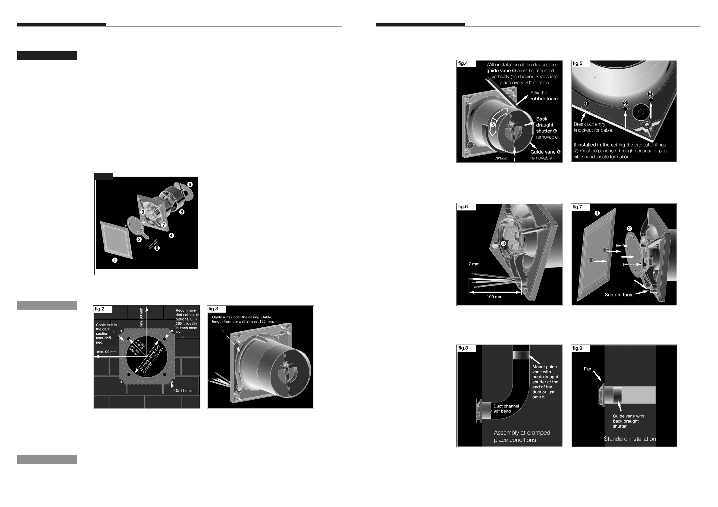
5. Guide vane removable at reduced installation depth
6. Removable back draught shutter
7. Cable grommet
8. Assembly kit
Ref:no. 71523101
with impeller
2 x screws with plugs for wall mounting
3.3 Wall or ceiling installation
3.4 Cable connections
1. Pull cable through grommet, don’t cut open!
2. Cut cable at least to length 180 mm and remove cable jacket at least 100 mm in length.
3. Connect fan according to wiring diagram (see page 5).
4. Run cable in the conduit. Ensure cable / grommett is sealed to maintain IP45.
NOTE
NOTE
3.0 Preparation for wall or ceiling installation (surface mounted)
The assembly and start-up of the fan unit should be carried out first after finishing all other work and after the final
cleaning in order to avoid damage and contamination of the fan unit.
The position of the cable exit is variable (see fig.2/3).
3.1 Cable exit from the wall
- Distance to the duct centre depending on cable exit 58/68 mm with a variable position under the casing.
- For a simple assembly an exit is recommended as shown (turnable by 90° in each case).
The optimal position is 45° each if the cable exit is directly at the position of the cable grommet.
- Duct inside diameter QT100T =100mm / QT120T =120mm and distance to room corners: at least 90 mm
- Mounting hole radius QT100T = 58mm / QT120T = 68mm
3.2 Drill holes
- Set casing against the wall, mark the holes and drill. Fasten with at least 2 screws and plugs. For surface installation
the casing is provided with a side entry knockout (Fig.5, Pos.1) for the cable ! The mains supply cable is to be kept in
such a way that no ingress of moisture is made possible along the cable.
- Length of single conductor 100 mm
- Length of stripped insulation 7 mm
- Strip plastic-sheathed cable flush with conduit.
1. Press cover of control board (2) on casing and
fasten with screws.
2. Snap in fascia. (1)
2
3

Installation and Operation Instructions
Installation and Operation Instructions
CHAPTER 4
ELECTRICAL
CONNECTION
WARNING
NOTE
CHAPTER 5
CLEANING AND
MAINTENANCE
CHAPTER 6
TROUBLESHOOTING
4.0 Electrical connection
All work must be carried out with the equipment fully isolated from the power supply. The electrical connection
is to be carried out in accordance with the relevant wiring diagram and are only to be done by a certified
electrician. The fans may not be operated with transformer controllers.
Fan should be protected by a 3A fuse at all times.
All relevant safety regulation, national standards and norms are to be adhered to.
4.1 Electronic control board
The electronic control board allows the operation with 2 speeds (75/90 m3hr) for QT100T and (150/170 m3hr) for
QT120T. The control board is fitted into a splash-proof casing.
EMV regulation
Important indication for the electromagnetic compatibility
Interference resistance according to DIN EN 55014-2 depending upon impulse form and energy rate of 1000 V to
4000 V. With operation with fluorescent tubes, switch power supplies, electronically regulated halogen bulbs etc. these
values can be exceeded.
In this case additional suppression shielding activities are necessary (L -, C or RC elements, protection diodes,
resistors).
5.0 Cleaning and maintenance
- Before cleaning, ensure that the fan is isolated from the power supply.
- Prevent unintentional restart !
- Clean device only with a damp cloth.
- The device is maintenance-free.
5.1 Dismantling of fascia
Procedure:
1. Isolate the device from the power supply and prevent unintentional restart!
2. Remove the fascia (1) by using the correct tool (e.g. screw driver) and applying light pressure on the spring catches
left and right of the fascia (Fig.10).
3. Unfasten the screws of the control board cover (2) (Fig.11).
6.0 Troubleshooting
- If the thermal protection trips this could be the result of dirt build-up, a hard running impeller and/or bearings.
Too high winding temperature through insufficient motor cooling, or too high air flow temperature could be the cause
of disturbance.
- Abnormal noises can mean worn out bearings.
- Vibrations can originate from an unbalanced or dirty impeller or due to the installation.
- Extreme performance reduction can occur if the fan must work against too high resistance of the ventilation system
or if there is a lack of sufficient supply air (causing also higher sound level).
Wiring diagram overview
QT100T - 75(90)m3/hr
QT120T - 150(170)m3/hr
M1/... N SS-917
M1/... NC
1 2
LN
L
N
1
2
WARNING
Electrical connection:
- Terminal N / L:
The supply voltage of 230 V is connected permanently to
terminalN/L
- Terminal 1:
The time functions are activated via terminal1.
The following functions are implemented:
1. Start delay (0 sec, 45 sec, 90 sec, 120 sec)
DIP-switch S1-2 (see wiring diagram SS-920.2)
After switching on terminal1, the fan starts first after the adjusted
delayed time. Thus a room can be entered for a short time (via
two-pole switch) e.g. during combined on/off switching with the
light without the fan being started for operation. Factory setting
approx. 120 sec.
2. Operation with push-button switch
During start delay the fan can be switched on via terminal1 with a
push-button switch at deactivated start delay (sampling pulse min.
0,5 sec.).
3. Run on time (6 min., 10 min., 15 min., 21 min.)
DIP-switch S3+4 (see wiring diagram SS-920.2)
After switching off terminal1, the fan keeps running and switches
off after the adjusted time automatically. Factory setting approx.
15 min.
4. Interval operation (0 hrs., 8 hrs., 12 hrs., 24 hrs.)
DIP-switch S5+6 (see wiring diagram SS-920.2)
The fan can be put in adjustable time intervals into operation automatically. After the adjusted run on time the fan switches off automatically. The intervaltime starts after the last switch off process
on terminal1 (time input), also with manualoperation in the meantime (terminal2). The manualoperation does not have influence on
the interval operation. The turn-on time in the interval operation
corresponds to the adjusted run on time. Factory setting approx. 0
hrs.
In delivered condition the intervaloperation is deactivated. The DIP
switches have to be adjusted according to the table for a desired
interval.
5. Changing the factory setting
DIP-switch (see wiring diagram SS-920.2). Isolate the unit from the
mains electric supply !
- Terminal 2:
The continuous operation is activated via terminal 2 (see wiring
diagram SS-917). With activated time function, the manualstage
(terminal2) is inactive.
Room lighting
In connection with the room lighting (terminal 1 or 2), a two-pole
switch must be used.
a) time function
a) Zeitfunktion
b) manual on
b) manuellEin
b)a)
Internalfunctionalprinciple / Jumper positionConnection client
SS-931
N
L
1
time function/- input
Zeit-Eingang
manual input
Manueller-Eingang
M1~
2
Jumper 1
A / B
A
Kl.1=
LN
Adjustment of DIP-switchs
1 2
QT ... T
on
off
1 2 3 4 5 6
LN
Important: Wiring in parallel
Wiring in parallel of several fans is not permitted.
- Jumper
Depending on the jumper setting, the fan QT100T runs with 75 or 90 m³/h or rather the fan
QT120T with 150 or 170 m³/h.
Jumper 1 (see wiring diagram SS-931)
QT100T / QT 120T
Position A – Factory setting
Kl. 1 = 75 m³/h / 150 m³/h, activation via time function
Kl.2 = 90 m³/h / 170 m³/h, manualon
Position B
Kl.1 = 90 m³/h / 170 m³/h, activation via time function
Kl.2 = 75 m³/h / 150 m³/h, manualon
Operation test – Test mode:
When applying the supply voltage the fan is in the test mode for 1 minute.
(Requirement: Factory setting of DIP-switch, see wiring diagram SS-920.2)
In this case the delayed start and the overrun function is deactivated within the first
minute, or for a switching cycle.
S1
1 2
Kl.2=
Einschaltv erzöger ung
Dela yed star t
Démarrage tempor isé
Nachlauf /
Einschaltz eit
Run on time /
Running time
Temporisation /
Durée de f onctionnement
Intervallz eit,
Einschaltdauer=
Nachlauf ze it
Interval time
Running time = Run on time
Durée inter valle
Durée de f onctionnement =
Temporisation
0 sec
45 sec
90 sec
120 sec
6 min
10 min
15 min
21 min
0 Std
8 Std
12 Std
24 Std
B
Kl.1=
Kl.2=
DIP-Schalter/
1 2
off
off
on
off
on
off
on
on
SS-920.2
S
Switch / Commutateur
3
4
off off
off
on
on
off
on on
55
off off
on
off on
on on
6
off
4
5
5

Addendum – 10/2016
The Building Regulations 2010, Statutory Instrument Part 9, paragraph 42, imposes a requirement
that testing and reporting of mechanical ventilation performance is conducted in accordance with an
approved procedure.
Compliance with this requirement by an assessed and registered ‘Competent Person’ should follow a
‘Best Practice’ process and adopt air flow measurement, Method A – The Unconditional Method –
using a suitable UKAS certified measuring instrument. Generically referred to as a ‘Zero Pressure
Air Flow Meter’ or ‘Powered Flow Meter’.
Further information on this method is detailed in NHBC Building Regulations Guidance Note G272a
10/13 and BSRIA ‘A Guide to Measuring air flow rates’ document BG46/2015
 Loading...