

Page 1
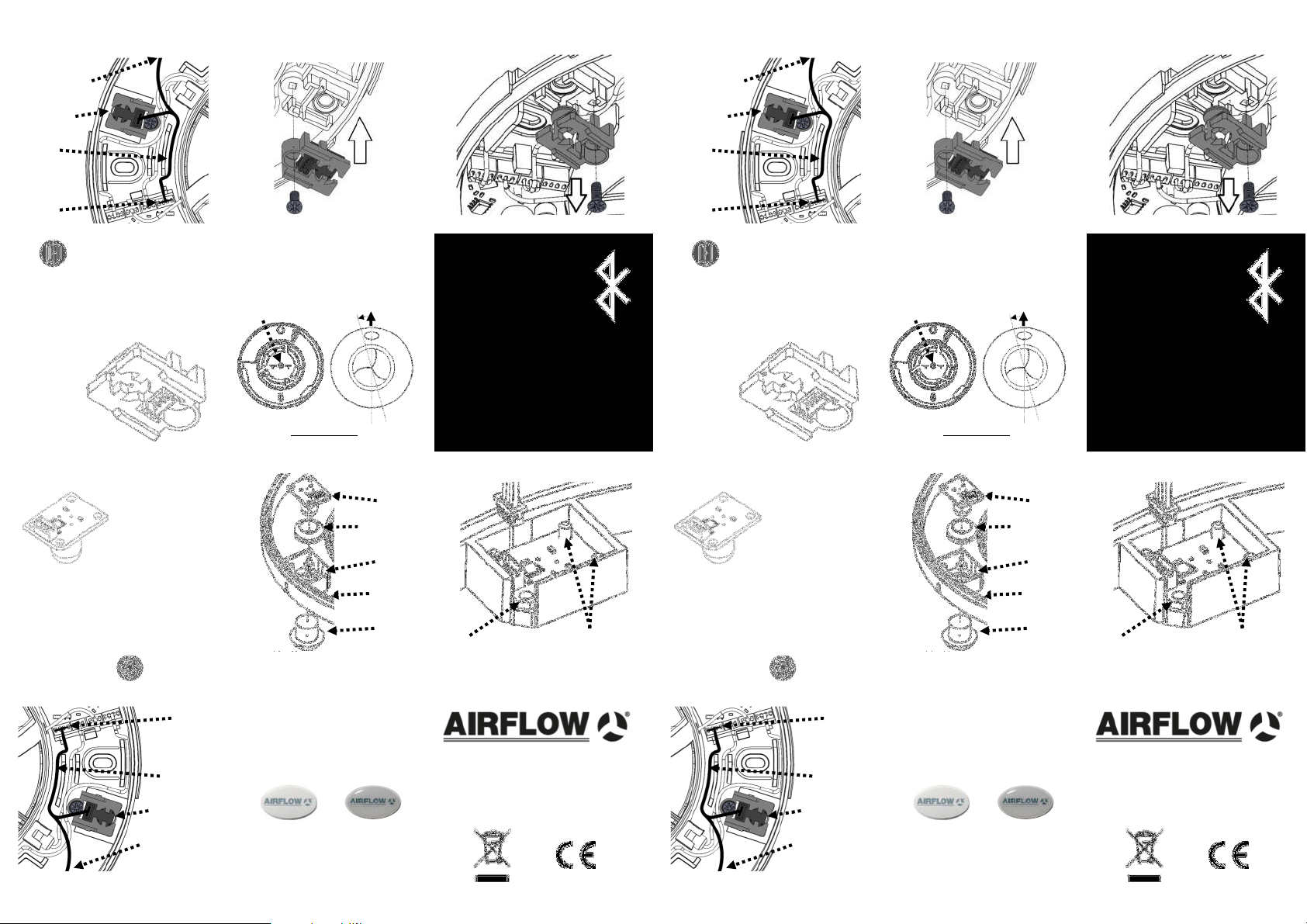
HT 2 HT 3 HT 4
slot (furthest left) as labelled above.
Timer module and connect to free module
Attach cable supplied into the Humidity
own holder) and screw into position.
shown above (the module will come with it’s
Place Humidity Timer sensor into location
from iCONsmart main body.
Remove existing Humidity Blank
slot (furthest left) as labelled above.
Timer module and connect to free module
Attach cable supplied into the Humidity
HT 2 HT 3 HT 4
own holder) and screw into position.
shown above (the module will come with it’s
Place Humidity Timer sensor into location
from iCONsmart main body.
Remove existing Humidity Blank
(see overleaf)
To MST module
HT module
Cable
Socket
Module
HT 1
(HT) Module
Humidity Timer
Motion Sensor Timer
(MST) Module
Allows the user to activate motion sensing
capabilities that trigger the iCONsmart
when motion is detected.
Once installed ensure that the Motion
Sensor is activated in ‘Settings’—’Motion
Sensor Activation’.
Module
Socket
Cable
HT module
(see overleaf)
To MST from
Module Socket
Connect this cable from MST into
module slot on the main body.
zone’ that it should stay within.
your room, as well as the ideal ‘health
in ‘myAirflow’ that shows the live state of
This gives access to the Room Heal th tab
range of the room from 40% to 100%.
Allows the user to control the humidity
Remove blanking grommet already in IPX
cover. Replace with MST sealing grommet.
Position MST in sealing grommet and press
into seal ensuring location pins line up.
MST 1
NOTE: When purchasing one module,
one cable connector is supplied. When
purchasing the combination of both
modules (MSHT) you will be supplied with
one connector that will fit the module
socket and both modules.
Firmly push white oval lens cap from
inside the front cover and replace with
translucent lens supplied with MST
module.
MST 4
Locking screw
White Lens
Translucent Lens
Fan Preparation
MST
MST Sealing
Grommet
MST tray
location
Under side
of IPX Cover
Blanking
Grommet
and lift off to show main body.
Remove locking screw from IPX cover
remove.
cover and twist anticlockwise to
Remove screw from bottom of front
Screw
Front Cover IPX Cover
Cable
Exit
Plug the cable provided into the MST
terminal once secured in IPX cover.
MST 2
Disposal
Do not dispose of with household waste.
Please recycle where facilities exist.
Check with your local authority for recycling
advice.
MST 5
Location Pins
iCONsmart Micro Modules
MST 3
(see overleaf)
To MST module
HT module
Cable
Socket
Module
HT 1
(HT) Module
Humidity Timer
Motion Sensor Timer
(MST) Module
Allows the user to activate motion sensing
capabilities that trigger the iCONsmart
when motion is detected.
Once installed ensure that the Motion
Sensor is activated in ‘Settings’—’Motion
Sensor Activation’.
Module
Socket
Cable
HT module
(see overleaf)
To MST from
Module Socket
Connect this cable from MST into
module slot on the main body.
zone’ that it should stay within.
your room, as well as the ideal ‘health
in ‘myAirflow’ that shows the live state of
This gives access to the Room Heal th tab
range of the room from 40% to 100%.
Allows the user to control the humidity
Remove blanking grommet already in IPX
cover. Replace with MST sealing grommet.
Position MST in sealing grommet and press
into seal ensuring location pins line up.
MST 1
NOTE: When purchasing one module,
one cable connector is supplied. When
purchasing the combination of both
modules (MSHT) you will be supplied with
one connector that will fit the module
socket and both modules.
Firmly push white oval lens cap from
inside the front cover and replace with
translucent lens supplied with MST
module.
MST 4
Locking screw
White Lens
Translucent Lens
Fan Preparation
MST
MST Sealing
Grommet
MST tray
location
Under side
of IPX Cover
Blanking
Grommet
and lift off to show main body.
Remove locking screw from IPX cover
remove.
cover and twist anticlockwise to
Remove screw from bottom of front
Screw
Front Cover IPX Cover
Cable
Exit
Plug the cable provided into the MST
terminal once secured in IPX cover.
MST 2
Disposal
Do not dispose of with household waste.
Please recycle where facilities exist.
Check with your local authority for recycling
advice.
MST 5
iCONsmart Micro Modules
Location Pins
MST 3
Page 2
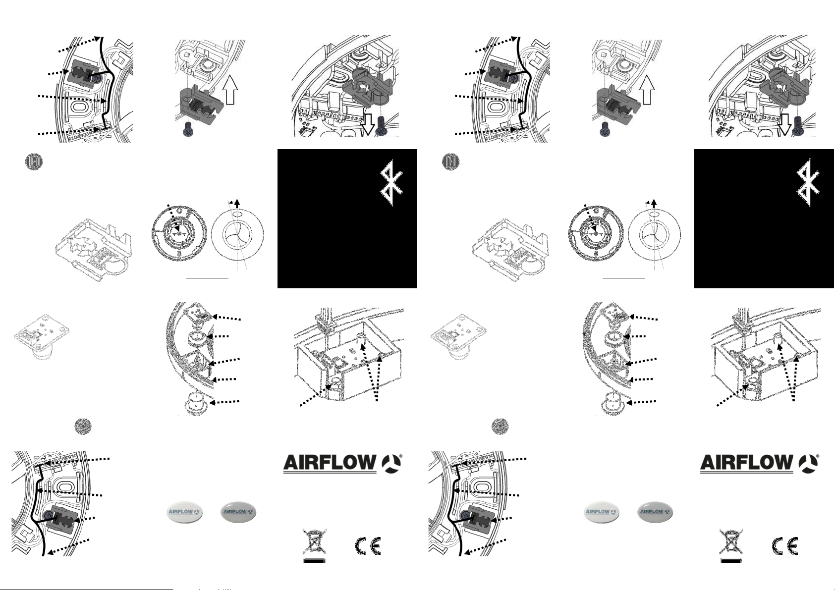
HT 2 HT 3 HT 4
slot (furthest left) as labelled above.
Timer module and connect to free module
Attach cable supplied into the Humidity
own holder) and screw into position.
shown above (the module will come with it’s
Place Humidity Timer sensor into location
from iCONsmart main body.
Remove existing Humidity Blank
slot (furthest left) as labelled above.
Timer module and connect to free module
Attach cable supplied into the Humidity
HT 2 HT 3 HT 4
own holder) and screw into position.
shown above (the module will come with it’s
Place Humidity Timer sensor into location
from iCONsmart main body.
Remove existing Humidity Blank
(see overleaf)
To MST module
HT module
Cable
Socket
Module
HT 1
(HT) Module
Humidity Timer
Motion Sensor Timer
(MST) Module
Allows the user to activate motion sensing
capabilities that trigger the iCONsmart
when motion is detected.
Once installed ensure that the Motion
Sensor is activated in ‘Settings’—’Motion
Sensor Activation’.
Module
Socket
Cable
HT module
(see overleaf)
To MST from
Module Socket
Connect this cable from MST into
module slot on the main body.
zone’ that it should stay within.
your room, as well as the ideal ‘health
in ‘myAirflow’ that shows the live state of
This gives access to the Room Heal th tab
range of the room from 40% to 100%.
Allows the user to control the humidity
Remove blanking grommet already in IPX
cover. Replace with MST sealing grommet.
Position MST in sealing grommet and press
into seal ensuring location pins line up.
MST 1
NOTE: When purchasing one module,
one cable connector is supplied. When
purchasing the combination of both
modules (MSHT) you will be supplied with
one connector that will fit the module
socket and both modules.
Firmly push white oval lens cap from
inside the front cover and replace with
translucent lens supplied with MST
module.
MST 4
Locking screw
White Lens
Translucent Lens
Fan Preparation
MST
MST Sealing
Grommet
MST tray
location
Under side
of IPX Cover
Blanking
Grommet
and lift off to show main body.
Remove locking screw from IPX cover
remove.
cover and twist anticlockwise to
Remove screw from bottom of front
Screw
Front Cover IPX Cover
Cable
Exit
Plug the cable provided into the MST
terminal once secured in IPX cover.
MST 2
Disposal
Do not dispose of with household waste.
Please recycle where facilities exist.
Check with your local authority for recycling
advice.
MST 5
Location Pins
iCONsmart Micro Modules
MST 3
(see overleaf)
To MST module
HT module
Cable
Socket
Module
HT 1
(HT) Module
Humidity Timer
Motion Sensor Timer
(MST) Module
Allows the user to activate motion sensing
capabilities that trigger the iCONsmart
when motion is detected.
Once installed ensure that the Motion
Sensor is activated in ‘Settings’—’Motion
Sensor Activation’.
Module
Socket
Cable
HT module
(see overleaf)
To MST from
Module Socket
Connect this cable from MST into
module slot on the main body.
zone’ that it should stay within.
your room, as well as the ideal ‘health
in ‘myAirflow’ that shows the live state of
This gives access to the Room Heal th tab
range of the room from 40% to 100%.
Allows the user to control the humidity
Remove blanking grommet already in IPX
cover. Replace with MST sealing grommet.
Position MST in sealing grommet and press
into seal ensuring location pins line up.
MST 1
NOTE: When purchasing one module,
one cable connector is supplied. When
purchasing the combination of both
modules (MSHT) you will be supplied with
one connector that will fit the module
socket and both modules.
Firmly push white oval lens cap from
inside the front cover and replace with
translucent lens supplied with MST
module.
MST 4
Locking screw
White Lens
Translucent Lens
Fan Preparation
MST
MST Sealing
Grommet
MST tray
location
Under side
of IPX Cover
Blanking
Grommet
and lift off to show main body.
Remove locking screw from IPX cover
remove.
cover and twist anticlockwise to
Remove screw from bottom of front
Screw
Front Cover IPX Cover
Cable
Exit
Plug the cable provided into the MST
terminal once secured in IPX cover.
MST 2
Disposal
Do not dispose of with household waste.
Please recycle where facilities exist.
Check with your local authority for recycling
advice.
MST 5
iCONsmart Micro Modules
Location Pins
MST 3
 Loading...