

Page 1
www.airflow.com
USER’S
USER’S
MANUAL
MANUAL
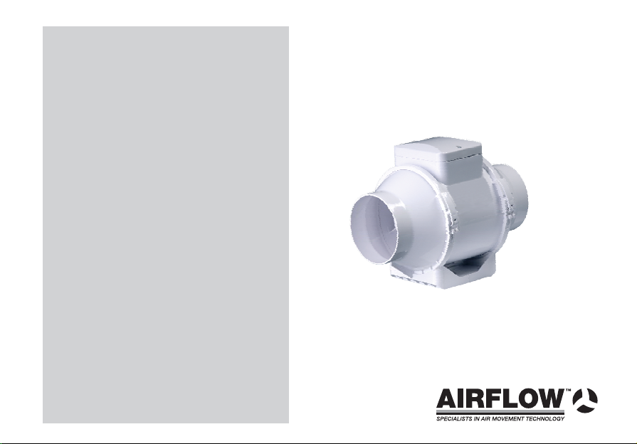
IN-LINE MIXED FLOW
Page 2
DESTINATION
The in-line fans with channels'
diameters ranging from 100 to 1 0 mm
are designed for installation in the ventilating systems
that require high pressure, powerful air flow.
The pumped air should not contain dust and other
solid admixtures, as well as sticky substances and
fibrous materials, the temperature of the transferred
air must not exceed +45°C. Fans are installed
horizontally or vertically and can be used both for
exhaust and for blowing ventilation. The fans are
manufactured as two-speed ones and are designed
for long-term operation without switching off mains.
By the type of protection against electrical shock the
fans belong to Class II.
The degree of protection against access to the
hazardous parts and water intrusions is IPX4.
Design of the fans is being constantly perfected, so some models
could differ from the ones, described in this certificate.
mixed flow
5
THE BASIC TECHNICAL DATA
The fans' designations, their parameters, connective
and mounting dimensions are provided in
tab.1,2 and on figs.1-5.
Fans are intended for connection to 230 V AC, 50 Hz.
It is permitted to use the fan under ambient
air temperature from +5 C to +40 C
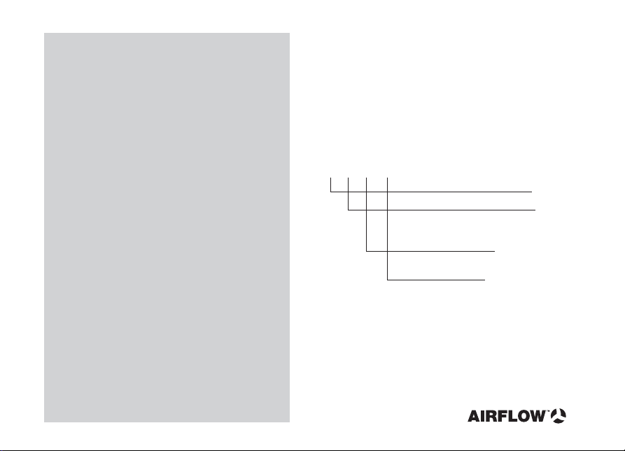
The scheme of designation of fans.
AV
ÕÕ
00
Õ
Type of fan
Air duct diameter
for connection
100 mm,125 mm,150 mm
S - increased
productivity
Ò - equipped
with timer
Notes.
The diameter of the air duct should match with
the diameter of fan delivery pipe.
An example of the fan record.
AV S125 is the fan of the higher power,
designed for the installation in a ventilating duct
with diameter of 125 mm.
2
Page 3
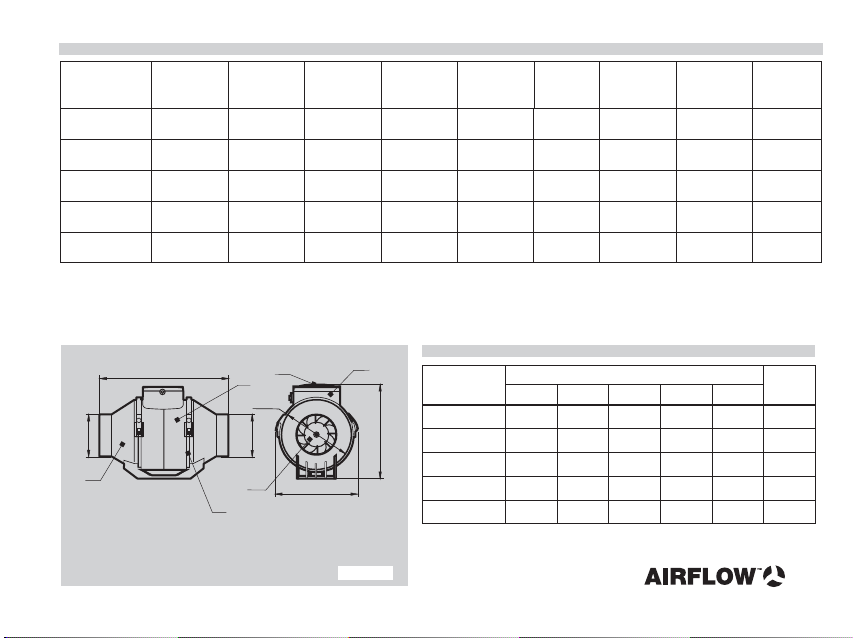
table 1
Typ e
AV 100
AV S100
AV 125
AV S125
AV 150
Consum
ption
,
Air flow
3
m/h
145\187
180\190
220\280
285\345
467\552 275\320
R.P.M.
2450\2500
2400\2500
2400\2500
2400\2500
2350\2450
current, A
0,16\0,25
0,21\0,28
0,19\0,26
0,21\0,28
0,24\0,34
Power,
25\28
47\65
28\38
47\65
54\76
Pressure,
W
Pa
121\135
330\350
107\138
335\357
Launching
capacity, ìF
-
4
-
4
4
Noise level,
dBA, 3 m
27\34
26\30
27\32
25\33
27\33
oltage, VV
230
230
230
230
230
Connection
layout
Fig.2/4*
Fig.3/5*
Fig.2/4*
Fig.3/5*
Fig.3/5*
The fans of the -series have two working speeds, that is shown in the tab. 1 with record through a fraction:
in the numerator the minimum velocity, in the denominator the maximal velocity.
AV
* - equipped with timer.
L
D
5
1 - body;
2 - terminal box;
3 - terminal box cover;
4 - impeller;
5 - jet;
6 - clamp.
3
1
D1
D
4
6
2
B
figure 1
table 2
Typ e
H
AV 100
100AV S
AV 125
125AV S
AV 150
DD1
96
96
123
123
148
Sizes, mm
126
185
136
185
185
B
H
190
165
250
220
165
190
220
250
220
250 952
3
L
246
367
246
952
Weight
kg
,51
3,4
,41
3,0
3,3
,
Page 4
DELIVERY SET
The delivery set includes:
- fan - 1 piece;
- dowels and screws - 4 pieces;
-;
user’s manual
- packing box.
MAINTENANCE
Maintenance of the fan is carried out only after
switching it off the mains. Maintenance consists
of periodical cleaning of the surfaces from dust
and dirt, when the fan is switched off the mains.
To remove the dust, use a soft dry brush or
compressed air. Blades of the impeller require careful
cleaning every 6 months. To do this, dismantle the
fan from the channel, take off the clamps 6 and r
emove the body 1. Using the water solution and
detergent, wash the blades of the turbine, avoiding
fluid intrusion onto the electric motor.
STORAGE RULES
Store the fan in the manufacturer's packaging in
an aerated premise at the temperature from
+5°C to + 40°C and relative humidity of the air
of not more than 80 % (at T = 25°C).
SAFETY REQUIREMENTS
By the type of protection against electrical shock the fans belong to the
Class II.
The degree of protection against access to the hazardous parts and
water penetration is IPX4.
All actions, related to connection of fans to the mains and
adjustment of the timer turn-off delay time are to be carried
only if the mains voltage is switched off.
RECOMMENDATIONS
For horizontal installation of the fan, to place an air duct with the length
of not less than 1m at the suction pipe side; for vertical installation
of the fan, it is necessary to place a canopy top at the suction pipe side.
Connection of the fans is carried out by a specialist electrician who
has a special access to the operations performed.
Operation of the fans outside the working temperature range is forbidden,
as well as exploitation in premises with aggressive impurities in the air.
Before connection of the fan to the mains it is necessary to ensure
that there are no visible damages of impeller, body, lattice, as well
as extraneous objects in the blowing part of the body,
which can damage runner vanes.
Maintenance and repair of the fan should be carried out only
after its switching off the mains.
ATTENTION!
Operation of the fan with extraneous subjects in the blowing part
of the body, which can damage or jam the runner vanes, is forbidden.
Precautions must be taken to avoid the black-flow of gases
into the room from the open flue of gas or other
appliances.
fuel-burning
4
Page 5
INSTALLATION AND CONNECTION
OF THE FAN TO THE MAINS
The fan (fig.1) consists of the body 1 with fixed
electric motor and impeller 4; launching capacitor
fixed inside the terminal box 2 (for
125 );
AV AV
terminal box cover 3, pipes 5 (pipe diameter
corresponds to the diameter of the air duct);
quick-detachable clamps 6.
Air moving direction of the air should coincide
with the direction of the arrow on the fan body.
For the installation of the fan it is necessary
to carry out following operations:
- remove two clamps 6 and to take out the body 1;
- drill holes for dowels, according to the coupling
sizes and fix the pipes by means of 4 screws;
- insert the body 1 and fix it with clamps 6.
- connect air ducts of the relevant diameter.
Connection of the fan to the single-phase
circuit should be carried out through the switch
built-in into the stationary wiring. The gap between
contacts of switch at all poles should be not less
than3mm.
150S and
5
AV S,
100
Connection layouts of the fan to the stationary wiring
are shown on figs. 2-5.
In case of one-speed operation at one speed,
it is necessary to connect the wire L of the mains
to one of the terminals, corresponding to the s
elected rotation speed:
L maximum speed
H
L minimum speed
L
Speed of the fan is switched using external switch S1.
Fan with timer T (figs 4, 5) ensures automatic
turning off the fan after certain time from 2 to 30 minutes,
set up by the timer. Turn-off delay time is adjusted, using
the handle of potentiometer, rotating it clockwise to increase
the delay time and anticlockwise to decrease it. Layout in fig.5
shows how to operate the fan using lighting switch. For such
connection, lighting lamp H is turned off by the switch, and the fan
continues working during the time, set up by the timer.
To connect the fan to the mains, it is necessary to:
- remove the cover from terminal box,
- extend electric wires through the gasket ring,
located on the terminal box,
- remove insulation from the ends of wires by5-6mm,
insert them into appropriate terminals until insulation is rested
against the metal part of the terminals, and fix them with screws,
- place back the terminal box cover.
ATTENTION!
Launching the fan, equipped with timer, occurs within
approximately 5 s after turning on external switch S2.
Page 6
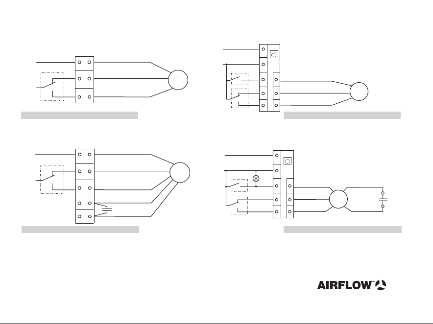
Connection diagram of fans of the 100, 125-seriesAV AV
Õ
N
L
figure 2
S1
max
min
N
L
L
white
black
H
brown
L
Ì
Connection diagram of fans of the 100T, 125T-seriesAV AV
N
L
S2
S1
max
min
N
L
LT
L
L
Ò
-
+
+
white
H
L
black
brown
Ì
figure 4
Connection diagram of fans of the 125S, -seriesAV AV AV100S, 150
N
S1
L
figure 3
X terminal box;
-
M electric motor;
-
C capacitor;
-
L minimum rotation speed;
-
L
L - maximum rotation speed;
H
max
min
Õ
N
L
H
L
L
white
black
red
yellow
brown
S1 external switch of fan speed,
-
S2 external switch;
-
T-timer
Connection diagram of fans of the 125S , -seriesAV T AV T AV T100S , 150
Ò
N
L
LT
L
L
-
H
L
N
Ì
installed in case of necessity
of switching speed during operation;
L
S2
max
S1
min
+
+
white
black
red
yellow
Ì
brown
figure 5
6
Page 7
THE ACCEPTANCE CERTIFICATE
The fan complies with the European norms
and directives.
Model
Manufacturing
Stamp of the inspector
Sold
The name of the trading company, stamp of the shop
Date of sale
AIRFLOW10EN-03
 Loading...