

Airflow Aria 100B, Aria 100PC, Aria 100T, Aria 100HT, Aria 100MST Installation Instructions
Page 1
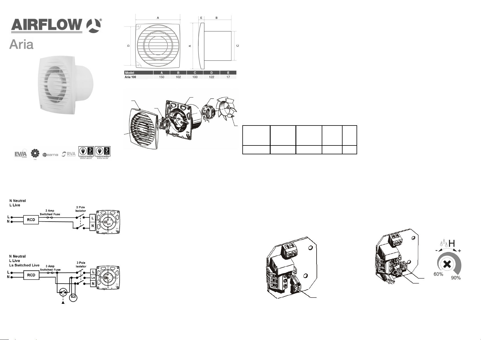
Fan Dimensions
Range Overview
Electrical Installation
Fan Range
Installation and Operating Guide
Aria 100B - 90000687
Aria 100PC - 90001400
Aria 100T - 90000688
Aria 100HT - 90000689
Aria 100MST - 90000690
Electrical Installation
Aria 100B, Aria 100PC, Aria 100MST
Wiring for fans with no external switching
Aria 100T, Aria 100HT
Wiring for fans with external switching
Note: An external switch can be connected to the Live
for Aria 100B and Aria 100PC fans.
Page 5 of 16 Page 6 of 16 Page 7 of 16 Page 8 of 16
Aria 100
Fan Overview
1
5
2
1.Cover, 2.Casing, 3.Motor
4. Impeller, 5.Control.
Page 2 of 16
3
Mechanical Installation
Aria fans can be wall mounted.
For mounting the fan, a ø100mm hole is required for
the spigot, as well as at least two holes for the
mounting screws. When mounting the fan, remove
the front cover and place the fan into the pre drilled
hole. Make sure that the spigot fits into any preinstalled ducting. Wire the fan appropriately
according to page 5, ensuring that the cables from
the fan are routed through the provided cable hole.
Use at least two mounting screws to secure the fan to
the ceiling or wall ensuring not to over tighten and
replace the front cover with the retention screw.
Ensure free running of the fan impeller and that
flexible duct connections are not over tightened to the
fan outlet spigot.
Airflow recommends that rigid ducting is used instead
of flexible ducting, this will ensure maximum
performance.
Aria fans are designed for ventilation of domestic
premises i.e. bathrooms, toilets and shower rooms.
They are recommended for 'through the wall'
installation.
The Aria 100B model may be used as a simple extract
fan operated by a remote switch.
The Aria 100PC model may be used as a simple
extract fan operated by a remote switch and a pull cord.
The Aria 100T model includes an adjustable timer
function 2 to 30 minutes.
The Aria 100HT model includes an adjustable timer
function 2 to 30 minutes and an adjustable humidity
function 60 to 90% RH.
The Aria 100MST models includes adjustable timer
function 2 to 30 minutes and motion sensing.
4
Fan Size
100mm 66.5 31.8 6 26
Max flow,
m3/h
Max Pressure
Pa
Page 3 of 16
Nominal
power, W
Fan Adjustment - Timer
The fan with timer function switches on when the
voltage is supplied to the Ls terminal via an external
switch.
After the voltage to the Ls terminal is disconnected
the fan continues to run for the set run on timer
period between 2 and 30 minutes. The run on timer
period is adjusted by turning the potentiometer (T)
clockwise to increase and anti-clockwise to decrease.
T
The Aria fan range is IPX4 rated and is suitable for
mounting in Zone 2 in bathrooms, toilets, kitchens,
utility rooms and inside shower cubicles when installed
with a 30mA RCD. In addition AFDD protection is also
required.
The fan requires a 220 - 240V 50Hz single phase
supply. Class II equipment. BS EN 60417. An external
3A fuse is required for each fan unit. Cable sizes
(max): Fixed flat wiring 2 core 1mm2, 3 core 1/1.5mm
All electrical installation work to be carried out by a
competent person in compliance with the relevant
Building Regulations/Standards as well as the current
edition of BS7671 (IET Wiring Regulations).
Important Notes
The Aria range also complies with the requirements of
the EU norms and directives. Do not place the
ventilator near direct heat sources, e.g. radiant
Noise
level
dB(A)
heaters, or where temperatures can exceed 40°C
(104°F). Precautions must be taken to avoid back flow
of gases in rooms with open flue fuel burning
appliances.
Page 4 of 16
Fan Adjustment - Humidity & Timer
Humidity and timer functions are activated when the
voltage is supplied to the Ls terminal via an external
switch or when the humidity level rises above the set %
RH level (adjustable between 60 and 90% RH).
After the voltage to the Ls terminal is disconnected or
the humidity level falls below the set %RH level, the fan
continues to run for the set overrun period between 2
and 30 minutes.
T
H
The humidity level is adjusted by turning the
potentiometer (H) clockwise to increase and anticlockwise to decrease.
To set the maximum humidity level the potentiometer
(H) has to set at the max position (90%).
See page 7 “Fan adjustment -Timer” for timer
adjustment instructions.
2
Page 2
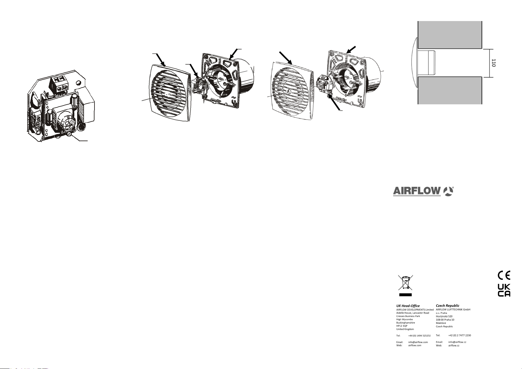
Fan Adjustment - Motion Sensor & Timer
The fan with motion sensor and timer function
switches on when movement is detected between a
distance of 1 and 4 meters from the fan. The sensor
has a detection angle of 100° horizontally.
Once movement ceases, the fan continues to run for
the set overrun period which is adjustable between 2
and 30 minute.
Fan Assembly - Timer / Humidity & Timer
Front cover
Electronic
Control
T & HT
Fan body
assembly
Front
Fan Assembly - Motion Sensor & Timer
Fan body
assembly
Through The Wall Installation
T
Page 9 of 16
Best Practice Recommendations
The Building Regulations 2010, Statutory
Instrument Part 9, paragraph 42, imposes a
requirement that testing and reporting of
mechanical ventilation performance is conducted in
accordance with an approved procedure.
Compliance with this requirement by an assessed
and registered ‘Competent Person’ should follow a
‘Best Practice’ process and adopt air flow
measurement, Method A – The Unconditional
Method – using a suitable UKAS certified
measuring instrument. Generically referred to as a
‘Zero Pressure Air Flow Meter’ or ‘Powered Flow
Meter’.
Further information on this method is detailed in
NHBC Building Regulations Guidance Note G272a
10/13 and BSRIA ‘A Guide to Measuring air flow
rates document BG46/2015.
Page 10 of 16
Maintenance
SAFETY FIRST: ALWAYS ISOLATE THE FAN UNIT
FROM THE POWER SUPPLY BEFORE REMOVING
THE COVER.
When installed according to these instructions the
Aria range is completely safe. The materials used do
not constitute a hazard.
Cleaning
The external housing of the fan can be wiped with a
damp cloth. Do not use household cleaners
containing abrasives.
Note: Always isolate the fan when cleaning. Never
clean any parts of the fan assembly by immersing in
water or using a dishwasher.
Warning
This appliance can be used by children aged from 8
years and above and persons with reduced physical,
sensory or mental capabilities or lack of experience
and knowledge if they have been given supervision
or instruction concerning use of the appliance in a
safe way and understand the hazards involved.
Children shall not play with the appliance. Cleaning
and user maintenance shall not be made by children
without supervision
Page 14 of 16 Page 15 of 16 Page 16 of 16
Electronic
control
Page 11 of 16
Warranty
Airflow guarantees the Aria for 2 years from date of
purchase against faulty material or workmanship,
Applicable to unites installed and used in the UNITED
KINGDOM.
Warranty covers the fan, not the re-instalaltion of this
if required. In the event of any defective parts being
found, Airflow Developments Ltd reserves the right to
repair, or at our discretion replace without charge
provided the unit:
• Has been installed in accordance with the fitting
and wiring instructions supplied with each unit.
• Has not been connected to an unsuitable electrical supply.
• Has not been subjected to misuse, neglect or
damage.
• Has not been modified or repaired by any person
not authorised by Airflow Developments Ltd.
• Has been installed by a person who is recognised
as a competent person who is part of a competent
scheme provider (e.g. NICEIC Ventilation
Scheme).
To maximise airflow rigid ducting should be used.
Where flexible ducting is used the diameter must be
maintained and it is good ventilation practice that the
ducting is extended to 90% of its possible length in
order to maintain the best possible airflow. Ensure
that flexible duct connections are not over tightened
to the fan outlet spigot.
The fan and ducting should be installed in accordance
with the requirements of the Domestic Ventilation
Compliance Guide, part of the Building Regulations.
Page 12 of 16
Airflow Developments Ltd shall not be liable for any
loss, injury or other consequential damage, in
the event of a failure of the equipment or arising
from, or in connection with, the equipment
excepting only that nothing in this condition shall be
construed as to exclude or restrict liability for
negligence. Full details at airflow.com/terms
This warranty does not in any way affect any
statutory or other consumer rights.
Disposal
Do not dispose of with household waste.
Please recycle where facilities exist.
Check with your local authority for recycling
advice.
Germany
Airow Lutechnik GmbH
Wolbersacker 16
53359 Rheinbach
Germany
Tel: +49 (0) 222 69205 0
Email: info@airow.de
Web: airow.de
80000510 Issue 4 02/21
 Loading...