


SmartCool™
Downflow – Precision Air Conditioning
R410A
Installation, Maintenance and
Commissioning
SmartCoolTM - D Precision Air Conditioning
About Airedale Products & Customer Services
Warranty
Warranty is only valid in the event that
CAUTION
Spares
Training
Customer Services
Legal Notices
All AIAC products or parts (non consumable) supplied for installation within the UK mainland and commissioned by an AIAC engineer, carry a full Parts & Labour warranty for a period of 12 months from the date of commissioning or 18 months from the date of despatch, whichever is the sooner.
Parts or Equipment supplied by AIAC for installation within the UK or for Export that are properly commissioned in accordance with AIAC standards and specification, not commissioned by an AIAC engineer; carry a 12 month warranty on non consumable Parts only from the date of commissioning or 18 months from the date of despatch, whichever is the sooner.
Parts or equipment installed or commissioned not to acceptable AIAC standards or specification invalidate all warranty.
In the period between delivery and commissioning the equipment: is properly protected & serviced as per the AIAC installation & maintenance manual provided where applicable the glycol content is maintained to the correct level.
In the event of a problem being reported and once warranty is confirmed as valid under the given installation and operating conditions, the Company will provide the appropriate warranty coverage (as detailed above) attributable to the rectification of any affected Airedale equipment supplied (excluding costs for any specialist access or lifting equipment that must be ordered by the customer).
Any spare part supplied by Airedale under warranty shall be warranted for the unexpired period of the warranty or 3 months from delivery, whichever period is the longer.
To be read in conjunction with the Airedale Conditions of Sale - Warranty and Warranty Procedure, available upon request.
Warranty cover is not a substitute for maintenance. Warranty cover is conditional to maintenance being carried out in accordance with the recommendations provided during the warranty period. Failure to have the maintenance procedures carried out will invalidate the warranty and any liabilities by Airedale International Air Conditioning Ltd.
A spares list for 1 3 and 5 years will be supplied with every unit and is also available from our Spares department on request.
As well as our comprehensive range of products, Airedale offers a modular range of Refrigeration and Air Conditioning Training courses, for further information please contact Airedale.
For further assistance, please e-mail: enquiries@airedale.com or telephone:
UK Sales Enquiries |
+ 44 (0) 113 239 1000 |
enquiries@airedale.com |
International Enquiries |
+ 44 (0) 113 239 1000 |
enquiries@airedale.com |
Spares Hot Line |
+ 44 (0) 113 238 7878 |
spares@airedale.com |
Airedale Service |
+ 44 (0) 113 239 1000 |
service@airedale.com |
Technical Support |
+ 44 (0) 113 239 1000 |
tech.support@airedale.com |
Training Enquiries |
+ 44 (0) 113 239 1000 |
marketing@airedale.com |
For information, visit us at our Web Site: www.airedale.com
AIAC Ltd endeavours to ensure that the information in this document is correct and fairly stated, but none of the statements are to be relied upon as a statement or representation of fact. AIAC Ltd does not accept liability for any error or omission, or for any reliance placed on the information contained in this document.
The development of Airedale products and services is continuous and the information in this document may not be up to date. It is important to check the current position with AIAC Ltd at the address stated. This document is not part of a contract or licence unless expressly agreed.
No part of this document may be reproduced or transmitted in any form or by any means, electronic or mechanical, including photocopying, recording, or information storage and retrieval systems, for any purpose other than the purchaser’s personal use, without the express written permission of AIAC Ltd.
Cover image is the SC25D100-X2X2-0; Controller display is for illustration only.
ã 2013 Airedale International Air Conditioning Limited. All rights reserved. Printed in the UK.
2
Precision Air Conditioning
Installation, Maintenance and Commissioning Manual :6877419 02/2013

Precision Air Conditioning |
SmartCoolTM – D |
About Airedale Products & Customer Services...................................................................... |
2 |
Warranty................................................................................................................................. |
2 |
Spares.................................................................................................................................... |
2 |
Training .................................................................................................................................. |
2 |
Health and Safety....................................................................................................................... |
6 |
Specifier’s Guide Indoor Unit ................................................................................................... |
7 |
Nomenclature......................................................................................................................... |
7 |
Introduction ............................................................................................................................ |
8 |
System Configurations.............................................................................................................. |
9 |
Dual Circuit............................................................................................................................. |
9 |
Dual Cool ............................................................................................................................. |
10 |
Chilled Water........................................................................................................................ |
11 |
Installation Data ....................................................................................................................... |
12 |
Dimensions .......................................................................................................................... |
12 |
Positioning............................................................................................................................ |
13 |
Minimum Unit Clearance...................................................................................................... |
13 |
Electrical Services Incoming Cable ...................................................................................... |
14 |
Incoming Mains Gland Plate ................................................................................................ |
14 |
Weights ................................................................................................................................ |
15 |
Refrigerant Pipe Sizing Guide .............................................................................................. |
18 |
Refrigerant Charging Guide ................................................................................................. |
19 |
Packaged Unit Pre-Charged Refrigerant Volumes............................................................... |
21 |
Design Data – Water Cooled & Free Cooling....................................................................... |
22 |
System Pressure Strength Test ........................................................................................... |
23 |
System Leak Test ................................................................................................................ |
23 |
Evacuation ........................................................................................................................... |
24 |
Refrigerant Handling ............................................................................................................ |
25 |
Oil Charging Guide............................................................................................................... |
26 |
Pressure switch settings....................................................................................................... |
26 |
Compressor Oil Information ................................................................................................. |
27 |
Chilled Water System........................................................................................................... |
29 |
Humidification....................................................................................................................... |
29 |
Condensate Drain Pipework................................................................................................. |
32 |
Fitting Instructions ................................................................................................................ |
33 |
Pipe Clips............................................................................................................................. |
33 |
Condensate Drain Priming ................................................................................................... |
33 |
Checking for Leaks .............................................................................................................. |
33 |
Condensate Pump Operation............................................................................................... |
33 |
Fan Speeds.......................................................................................................................... |
35 |
Pipework Schematics.............................................................................................................. |
47 |
X2X2 .................................................................................................................................... |
48 |
X2C0 .................................................................................................................................... |
49 |
W2W2 .................................................................................................................................. |
50 |
W2C0 ................................................................................................................................... |
51 |
W2F0.................................................................................................................................... |
52 |
C000..................................................................................................................................... |
53 |
C0C0.................................................................................................................................... |
54 |
Controls .................................................................................................................................... |
55 |
PCO3 CONTROLLER.......................................................................................................... |
55 |
DISPLAY KEYPAD CONNECTIONS ................................................................................... |
56 |
Addressing the Display Keypad ........................................................................................... |
57 |
Use Of Extra Functions Buttons ........................................................................................... |
59 |
Navigation ............................................................................................................................ |
59 |
EVD EVO Driver Setup ........................................................................................................ |
60 |
Removable Plug and Play Display ....................................................................................... |
60 |
Driver Initialization (Driver Reset Function).......................................................................... |
61 |
Precision Air Conditioning
Installation, Maintenance and Commissioning Manual :6877419 02/2013
3
SmartCoolTM - D |
Precision Air Conditioning |
||||
|
|
Input / Outputs...................................................................................................................... |
|
63 |
|
|
Technical Data.......................................................................................................................... |
|
64 |
|
|
|
System Operating Limits......................................................................................................... |
|
64 |
|
|
|
Air Cooled Models (X2X2) ....................................................................................................... |
|
65 |
|
|
|
|
Performance Data – Air Cooled Models ............................................................................... |
|
65 |
|
|
|
Mechanical DataX2X2........................................................................................................ |
|
67 |
|
|
|
Electrical Data – X2X2.......................................................................................................... |
|
70 |
|
|
|
Sound Data – X2X2.............................................................................................................. |
|
73 |
|
|
|
Interconnecting Wiring –X2X2 .............................................................................................. |
|
74 |
|
|
Air Cooled and Chilled Water Models (X2C0) ........................................................................ |
|
76 |
|
|
|
|
Performance Data – Air Cooled & Chilled Water Models ..................................................... |
76 |
|
|
|
|
Mechanical Data –X2C0....................................................................................................... |
|
78 |
|
|
|
Electrical Data –X2C0 .......................................................................................................... |
|
84 |
|
|
|
Sound Data – X2C0.............................................................................................................. |
|
90 |
|
|
|
Waterside pressure drops – X2C0 ....................................................................................... |
|
91 |
|
|
|
Interconnecting Wiring – X2C0............................................................................................. |
|
92 |
|
|
Water Cooled Models (W2W2)................................................................................................. |
|
94 |
|
|
|
|
Performance Data – Water Cooled Models .......................................................................... |
|
94 |
|
|
|
Mechanical Data – W2W2.................................................................................................... |
|
95 |
|
|
|
Electrical Data – W2W2........................................................................................................ |
|
98 |
|
|
|
Sound Data - Water Cooled Models................................................................................... |
|
101 |
|
|
|
Waterside pressure drop - W2W2 ...................................................................................... |
|
102 |
|
|
|
Interconnecting Wiring – W2W2 ......................................................................................... |
|
103 |
|
|
Water Cooled and Chilled Water models (W2C0)................................................................ |
|
105 |
|
|
|
|
Performance Data –Water Cooled & Chilled Water Models ............................................... |
105 |
|
|
|
|
Mechanical Data – W2C0................................................................................................... |
|
107 |
|
|
|
Electrical DataW2C0 ........................................................................................................ |
|
113 |
|
|
|
Sound Data – W2C0........................................................................................................... |
|
119 |
|
|
|
Waterside Pressure Drops W2C0 ...................................................................................... |
|
120 |
|
|
|
Interconnecting Wiring – W2C0.......................................................................................... |
|
122 |
|
|
Water Cooled and Free Cooling (W2F0)............................................................................... |
|
124 |
|
|
|
|
Performance Data – Water Cooled & Free Cooling............................................................ |
|
124 |
|
|
|
Mechanical Data – W2F0 ................................................................................................... |
|
126 |
|
|
|
Electrical Data – W2F0....................................................................................................... |
|
132 |
|
|
|
Sound Data – W2F0........................................................................................................... |
|
138 |
|
|
|
Waterside Pressure Drops W2F0....................................................................................... |
|
139 |
|
|
|
Interconnecting Wiring – W2F0 .......................................................................................... |
|
141 |
|
|
Chilled Water Single Circuit (C000) ...................................................................................... |
|
143 |
|
|
|
|
Performance Data – Chilled Water – Single Circuit............................................................ |
|
143 |
|
|
|
Mechanical Data – C000 .................................................................................................... |
|
144 |
|
|
|
Electrical Data - C000......................................................................................................... |
|
147 |
|
|
|
Sound Data – C000............................................................................................................ |
|
149 |
|
|
|
Waterside Pressure Drop C000.......................................................................................... |
|
150 |
|
|
|
Interconnecting Wiring – C000 ........................................................................................... |
|
151 |
|
|
Chilled Water Dual Circuit (C0C0)......................................................................................... |
|
152 |
|
|
|
|
Performance Data – Chilled Water – Dual Circuit .............................................................. |
|
152 |
|
|
|
Mechanical Data – C0C0.................................................................................................... |
|
153 |
|
|
|
Electrical Data - C0C0........................................................................................................ |
|
156 |
|
|
|
Sound DataC0C0 ............................................................................................................. |
|
158 |
|
|
|
Waterside pressure drop - C0C0........................................................................................ |
|
159 |
|
|
|
Interconnecting Wiring – C0C0........................................................................................... |
|
160 |
|
|
Commissioning Data ............................................................................................................. |
|
161 |
|
|
|
|
Humidifier ........................................................................................................................... |
|
162 |
|
|
|
Head Pressure Control....................................................................................................... |
|
164 |
|
|
|
Precision Air Conditioning |
|
|
|
4 |
|
|
|
|
|
|
|
|
|
|
|
|
Installation, Maintenance and Commissioning Manual :6877419 02/2013 |
|
|
||
|
|
|
|
||

Precision Air Conditioning |
SmartCoolTM – D |
Electronically Commutated (EC) Fan Motor....................................................................... |
165 |
EC Fan interrogation .......................................................................................................... |
165 |
Suction Throttle Valve ........................................................................................................ |
166 |
Hot Gas Re-Heat (HGRH).................................................................................................. |
166 |
Commissioning procedure ................................................................................................... |
167 |
Commissioning Checklist ................................................................................................... |
167 |
Pre Commissioning checks................................................................................................ |
167 |
Fan Section ........................................................................................................................ |
168 |
Chiller /Glycol units ............................................................................................................ |
169 |
Heating............................................................................................................................... |
169 |
Humidification..................................................................................................................... |
170 |
Condenser.......................................................................................................................... |
170 |
Water cooled condenser .................................................................................................... |
170 |
Refrigeration circuit ............................................................................................................ |
171 |
Indoor unit optional extras.................................................................................................. |
173 |
Controls.............................................................................................................................. |
174 |
Maintenance ........................................................................................................................... |
175 |
Filter Changing................................................................................................................... |
175 |
3 Monthly............................................................................................................................ |
176 |
6 Monthly............................................................................................................................ |
176 |
12 Monthly.......................................................................................................................... |
176 |
Humidifier Bottle Change ................................................................................................... |
177 |
Evaporator Fan removal..................................................................................................... |
178 |
Troubleshooting Indoor Unit................................................................................................. |
179 |
Suction throttle valve (STV)................................................................................................ |
181 |
Hot Gas Re-heat (HGRH) .................................................................................................. |
181 |
Humidifier........................................................................................................................... |
181 |
Unit Alarms:........................................................................................................................ |
182 |
Specifier’s Guide Outdoor unit............................................................................................. |
190 |
Unit Identification................................................................................................................ |
190 |
Standard Features ............................................................................................................. |
191 |
Optional Extras - Energy Saving ........................................................................................ |
193 |
Installation data...................................................................................................................... |
194 |
Dimensions / Weights / Positioning .................................................................................... |
194 |
Unit Lifting .......................................................................................................................... |
199 |
Re-orientation to Vertical Discharge................................................................................... |
200 |
Positioning.......................................................................................................................... |
201 |
Siting Recommendations ................................................................................................... |
201 |
Pipework Connections........................................................................................................ |
201 |
Holding Charge .................................................................................................................. |
201 |
Pipework Installation - Good Practices............................................................................... |
201 |
Performance Data – Condensers....................................................................................... |
202 |
Performance Data – Dry Coolers ....................................................................................... |
204 |
Sound Data ........................................................................................................................ |
206 |
Mechanical Data – Condensers and Dry Coolers .............................................................. |
208 |
Dry Cooler Waterside Pressure Drop................................................................................. |
212 |
Electrical Data .................................................................................................................... |
213 |
Interconnecting Wiring........................................................................................................ |
213 |
Troubleshooting..................................................................................................................... |
214 |
Unmatched Outdoor Units.................................................................................................. |
214 |
Airedale Matched Outdoor Units ........................................................................................ |
215 |
Maintenance ........................................................................................................................... |
216 |
Precision Air Conditioning
Installation, Maintenance and Commissioning Manual :6877419 02/2013
5

SmartCoolTM - D |
Precision Air Conditioning |
General
Health and Safety
IMPORTANT |
The information contained in this manual is critical to the correct operation and |
|
maintenance of the unit and should be read by all persons responsible for the installation, |
|
commissioning and maintenance of this Airedale unit. |
Safety |
The equipment has been designed and manufactured to meet international safety |
|
standards but, like any mechanical/electrical equipment, care must be taken if you are to |
|
obtain the best results. |
CAUTION |
1 Installation, service and maintenance of Airedale equipment should only be |
|
carried out by technically trained competent personnel. |
CAUTION |
2 When working with any air conditioning units ensure that the electrical isolator |
|
is switched off prior to servicing or repair work and that there is no power to |
|
any part of the equipment. |
|
3 Also ensure that there are no other power feeds to the unit such as fire alarm |
|
circuits, BMS circuits etc. |
|
4 Electrical installation commissioning and maintenance work on this equipment |
|
should be undertaken by competent and trained personnel in accordance with local |
|
relevant standards and codes of practice. |
|
5 The refrigerant used in this range of products is classified under the COSHH |
|
regulations as an irritant, with set Workplace Exposure Levels (WEL) for |
|
consideration if this plant is installed in confined or poorly ventilated areas. |
|
6 A full hazard data sheet in accordance with COSHH regulations is available should |
|
this be required. |
Protective personal |
Airedale recommends that personal protective equipment is used whilst installing, |
equipment |
maintaining and commissioning equipment. |
Refrigerant Warning |
The Airedale SmartCool uses R410A refrigerant which is a high pressure refrigerant. It |
|
requires careful attention to proper storage and handling procedures. |
|
Use on manifold gauge sets designed for use with R410A refrigerant. Use only refrigerant |
|
recovery units and cylinders designed for high pressure refrigerants. |
|
R410A must only be charged in the liquid state. |
|
The refrigerant must be stored in a clean, dry area away from sunlight. The refrigerant |
|
must never be stored above 50°C. |
Manual Handling |
Some operations when servicing or maintaining the unit may require additional assistance |
|
with regard to manual handling. This requirement is down to the discretion of the |
|
engineer. Remember do not perform a lift that exceeds your ability. |
Environmental Policy |
It is our policy to: |
|
∙ Take a proactive approach to resolve environmental issues and ensure |
|
compliance with regulatory requirements. |
|
∙ Train personnel in sound environmental practices. |
|
∙ Pursue opportunities to conserve resources, prevent pollution and eliminate |
|
waste. |
|
∙ Manufacture products in a responsible manner with minimum impact on the |
|
environment. |
|
∙ Reduce our use of chemicals and minimise their release to the environment. |
|
∙ Measure, control and verify environmental performance through internal and |
|
external audits. |
|
∙ Continually improve our environmental performance. |
6
Precision Air Conditioning
Installation, Maintenance and Commissioning Manual :6877419 02/2013

Precision Air Conditioning |
SmartCoolTM – D |
Specifier’s Guide Indoor Unit
Nomenclature
|
|
International Example è |
SC19D065 - C000 -0 |
SC |
19 |
D |
065 |
- |
C |
0 |
0 |
0 |
- |
0 |
|
|
Dual Cool Example è |
SC31D065 - X2C0 -0 |
SC |
31 |
D |
065 |
- |
X |
2 |
C |
0 |
- |
0 |
|
|
Mono Cool Example è |
SC25D100 - X2X2 -0 |
SC |
25 |
D |
100 |
- |
X |
2 |
X |
2 |
- |
0 |
|
|
|
|
|
|
|
|
|
|
|
|
|
|
|
|
SmartCool |
SC |
|
|
|
|
|
|
|
|
|
|
|
|
|
Decimetre Case Width (dm) |
19 - 31 |
|
|
|
|
|
|
|
|
|
|
|
|
|
Upflow |
U |
|
|
|
|
|
|
|
|
|
|
|
|
|
Downflow |
D |
|
|
|
|
|
|
|
|
|
|
|
|
|
Nominal Capacity (kW) |
033-150 |
|
|
|
|
|
|
|
|
|
|
|
|
|
Separator |
- |
|
|
|
|
|
|
|
|
|
|
|
|
a l ) |
Air Cooled (Comp Indoor) |
X |
|
|
|
|
|
|
|
|
|
|
|
|
Water Cooled (Comp Indoor) |
W |
|
|
|
|
|
|
|
|
|
|
|
|
|
D u it 1 |
Chilled Water |
C |
|
|
|
|
|
|
|
|
|
|
|
|
o uc |
No Compressor |
0 |
|
|
|
|
|
|
|
|
|
|
|
|
/ |
|
|
|
|
|
|
|
|
|
|
|
|
|
|
o n C ir |
Single Compressor |
1 |
|
|
|
|
|
|
|
|
|
|
|
|
M |
Tandem Compressor |
2 |
|
|
|
|
|
|
|
|
|
|
|
|
( |
|
|
|
|
|
|
|
|
|
|
|
|
|
|
|
Inverter Compressor |
V |
|
|
|
|
|
|
|
|
|
|
|
|
|
No Option |
0 |
|
|
|
|
|
|
|
|
|
|
|
|
a l ) |
Air Cooled (Comp Indoor) |
X |
|
|
|
|
|
|
|
|
|
|
|
|
Water Cooled (Comp Indoor) |
W |
|
|
|
|
|
|
|
|
|
|
|
|
|
D u it 2 |
Free Cooling |
F |
|
|
|
|
|
|
|
|
|
|
|
|
o cu |
Chilled Water |
C |
|
|
|
|
|
|
|
|
|
|
|
|
/ |
|
|
|
|
|
|
|
|
|
|
|
|
|
|
on Cir |
|
|
|
|
|
|
|
|
|
|
|
|
|
|
No Compressor |
0 |
|
|
|
|
|
|
|
|
|
|
|
|
|
( |
Single Compressor |
1 |
|
|
|
|
|
|
|
|
|
|
|
|
M |
|
|
|
|
|
|
|
|
|
|
|
|
|
|
|
Tandem Compressor |
2 |
|
|
|
|
|
|
|
|
|
|
|
|
|
Inverter Compressor |
V |
|
|
|
|
|
|
|
|
|
|
|
|
|
Seperator |
- |
|
|
|
|
|
|
|
|
|
|
|
|
e |
400V 3PH 50Hz |
0 |
|
|
|
|
|
|
|
|
|
|
|
|
V o lt a g |
|
|
|
|
|
|
|
|
|
|
|
|
|
|
|
|
|
|
|
|
|
|
|
|
|
|
|
|
|
Note
Dual Cool units are defined as those having 2 different cooling mediums (i.e. R410A and Chilled Water [X2C0]).
Dual Circuit units are defined as those having 2 independent cooling circuits (i.e. X2X2 or C0C0).
General
Precision Air Conditioning
Installation, Maintenance and Commissioning Manual :6877419 02/2013
7
SmartCoolTM - D |
Precision Air Conditioning |
G ene
Introduction |
Designed to provide environmental precision air conditioning for applications such as |
||
|
telecommunication facilities, data centers, computer rooms, clean rooms and |
||
|
laboratories. |
|
|
|
|
|
|
|
|
Description |
Capacity kW (1) |
|
X2X2 |
Dual circuit direct expansion air cooled |
55 -122 |
|
X2C0 |
Dual cool direct expansion air cooled and |
(X2) 30 – 82.5 |
|
|
chilled water |
(C0) 50 - 102 |
|
W2W2 |
Dual circuit direct expansion water cooled |
54 -123 |
|
W2C0 |
Dual cool direct expansion water cooled and |
(W2) 30 - 85 |
|
|
chilled water |
(C0) 50 - 102 |
|
W2F0 |
Dual cool water cooled and glycol free cooling |
(W2) 30 - 86 |
|
|
|
(F0) 50 - 102 |
|
C000 |
Single circuit chilled water |
69 -149 |
|
C0C0 |
Dual circuit chilled water |
20 -102 |
(1) Based on nominal unit capacities
Full function units provide full control of temperature, humidity and filtration.
The modular design of the SmartCool allows grouping of differing model types and capacities to be installed side by side. The flexibility of this type of installation provides for multi-circuit functionality.
A full range of air cooled condensers is available with the direct expansion indoor units to provide a matched system with optional performance upgrade, refer to Outdoor Unit
A full range of Dry coolers is available to complement the free cooling indoor units. Dry coolers are a cost effective and safe solution against legionella.
Also available is a full range of Airedale water chillers to complement the chilled water indoor units.
The range has been designed and optimised for operation with ozone benign refrigerant
R410A.
CE Directive |
Airedale certify that the equipment detailed in this manual conforms with the following |
|
|
EC Directives: |
|
|
Electromagnetic Compatibility Directive (EMC) |
2004/108/EC |
|
Low Voltage Directive (LVD) |
2006/95/EC |
|
Machinery Directive (MD) |
89/392/EEC in the version |
|
|
2006/427/EC |
|
Pressure Equipment Directive (PED) |
97/23/EC |
To comply with these directives appropriate national & harmonised standards have been applied. These are listed on the Declaration of Conformity, supplied with each product.
8
Precision Air Conditioning
Installation, Maintenance and Commissioning Manual :6877419 02/2013
Precision Air Conditioning |
SmartCoolTM – D |
System Configurations
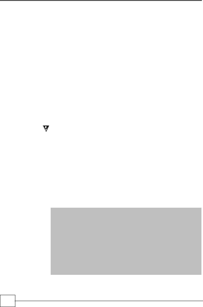
Dual Circuit
X2X2
The SmartCool X2X2 is an air cooled, direct expansion (DX), double circuit system linked to two separate, remotely mounted air cooled condensers.
Optimised for heat transfer using energy efficient refrigerant R410A in each circuit, the X2X2 system is located within the conditioned space, absorbing room heat and transferring it outside to the condensers.
By using one or more same/dissimilar sized scroll compressors across the X2X2 double circuit, part load efficiency can be maximised and capacity more precisely matched to application.
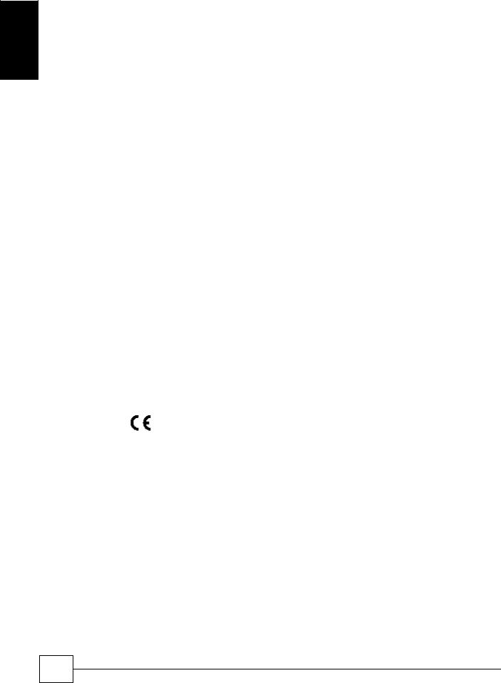
W2W2
Suitable for applications favouring reduced refrigerant charges, the SmartCool W2W2 is a double circuit system featuring, DX cooling within the case and dry coolers outside.
Warm room air is passed through two completely independent evaporator coils and an integral plate condenser transfers the heat load to the glycol solution which is then channelled outside to two air cooled dry coolers.
General
Precision Air Conditioning
Installation, Maintenance and Commissioning Manual :6877419 02/2013
9
SmartCoolTM - D |
Precision Air Conditioning |
G ene
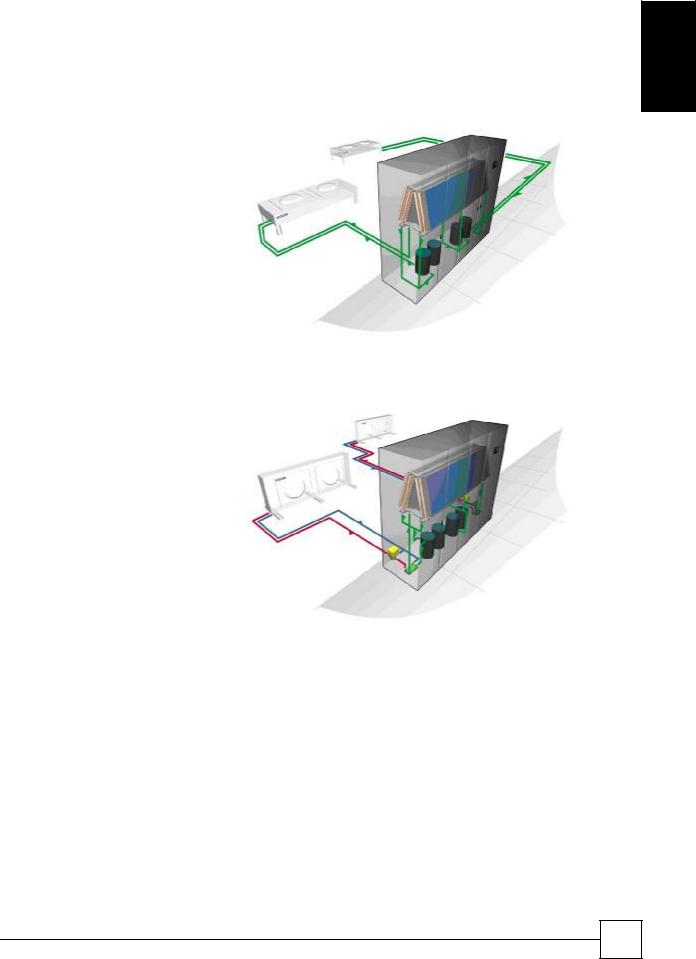
Dual Cool
X2C0
For redundancy in critical applications, the SmartCool dual cool X2C0 offers two different cooling mediums, air cooled DX and chilled water, within the same case.
The X2C0 system is managed by the Airetronix microprocessor to select which medium acts as the primary source of cooling or which acts as back-up, should the primary source fail or is unable to cope with the heat load.
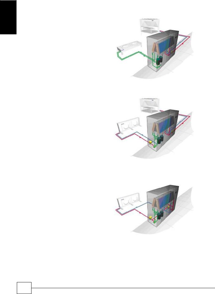
W2C0
For applications where a water cooled system is preferred over air cooled, the SmartCool W2C0 comprises two different cooling mediums within the same case: DX water cooled, as in the W2W2 system, and chilled water, as in the C000 system.
The Airetronix microprocessor elects which medium acts as the primary source of cooling and which as back-up, if the primary source fails or is unable to cope with the heat load.
W2F0
The W2F0 system includes a free-cooling coil in conjunction with the evaporator. In low ambient conditions, particularly in relation to the high temperatures and continuous system operation of a server environment, the W2F0 system will run with minimum energy. At times of higher ambient, sophisticated Airetronix controls technology will modulate the 3-way water regulating valves to transition from free cooling back to mechanical cooling.
Typically the SmartCool W2F0 single circuit freecooling system uses 46%* less energy than a standard air cooled DX system.
10
Precision Air Conditioning
Installation, Maintenance and Commissioning Manual :6877419 02/2013
Precision Air Conditioning
Chilled Water
C000
Where a chilled water single circuit system is preferred, warm room air is blown across the efficient cooling coils of the SmartCool C000 and the heat transferred to a chilled water system such as Airedale’s high efficiency TurboChill.
By controlling the 3-way water regulating valve, the intelligent Airetronix microprocessor can achieve precise control of temperature and humidity.
SmartCoolTM – D
General
C0C0
In the SmartCool C0C0 unit, the cooling coils are split into two independent systems, each with a 3-way water regulating valve, and cooled by chilled water from two separate chillers.
For extra security, the dual circuit configuration of
SmartCool C0C0 offers 2N redundancy.
Precision Air Conditioning |
11 |
|
Installation, Maintenance and Commissioning Manual :6877419 02/2013 |
||
|
SmartCoolTM - D |
Precision Air Conditioning |
Installation Data
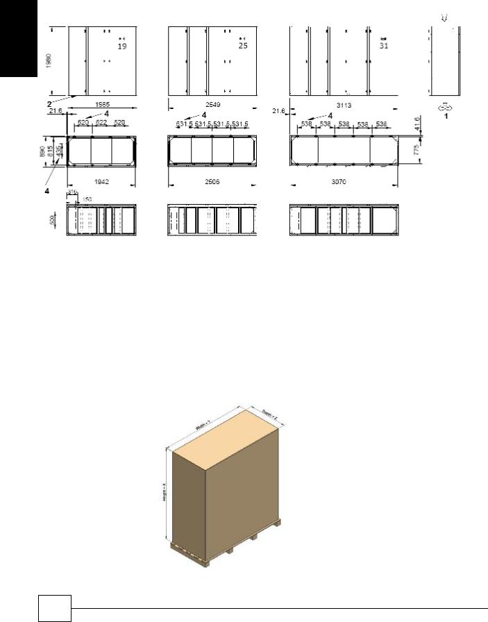
Dimensions
Standard Airflow Configuration (mm)
Installation
|
|
H x D x W |
SC19D |
mm |
1980 x 890 x 1985 |
SC25D |
mm |
1980 x 890 x 2549 |
SC31D |
mm |
1980 x 890 x 3113 |
(1)Forward or reversed air discharge available as standard on all products. Does not require configuring.
(2)Area denotes services entry location. For specific details please contact Airedale.
(3)Open base. Shaded area denotes air discharge.
(4)M6 fixing holes positions for mounting ceiling duct extensions or plenums.
Packed Dimensions |
For specific markets units shall be shipped, mounted on wooden pallet and covered with |
|
polythene. The pallet shall be mechanically fixed to the unit for transportation only |
|
(Please contact Airedale for this option) |
X = 160mm
Y = 50mm
Z = 50mm
12
Precision Air Conditioning
Installation, Maintenance and Commissioning Manual :6877419 02/2013
Precision Air Conditioning |
SmartCoolTM – D |
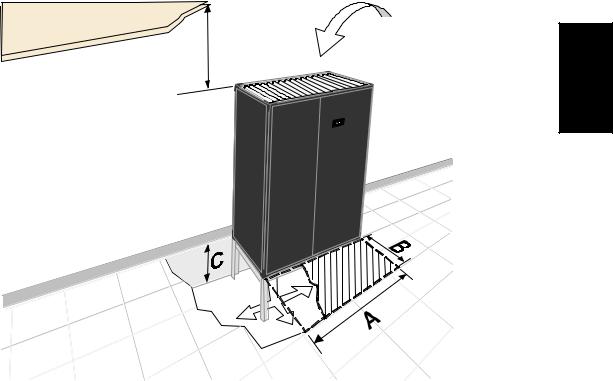
Positioning
(D)
(2)
(1)
Minimum Unit Clearance
Open & Enclosed Floorstand Option
|
|
|
|
|
A |
|
B |
C - Floorstand(3) |
||
SC19D |
|
mm |
1985 |
|
800 |
|
Min 200 – Max 750 |
|||
SC25D |
|
mm |
|
|
2549 |
|
|
800 |
|
(+ 50mm Feet Adjustable +/- |
|
|
|
|
|
|
20mm) (4) |
||||
SC31D |
|
mm |
3113 |
|
800 |
|
||||
|
|
|
|
|||||||
Minimum Ceiling Clearance- (D)
|
|
Forward Only |
Forward and 1 Side |
Forward and 2 Sides |
All Faces |
|
SC19D |
mm |
720 |
|
500 |
380 |
250 |
SC25D |
mm |
740 |
|
550 |
440 |
280 |
SC31D |
mm |
750 |
|
590 |
480 |
300 |
Notes
(1)Shown with optional open floor stand.
(2)Shaded area indicates minimum service and maintenance requirements. The unit must be installed with allowance for carpet tile clearance.
(3)Dimension C denotes recommended minimum/maximum floor stand height, refer to Airedale for special applications, please specify at order.
(4)Min = Threaded foot at minimum extension (additional to “C” dimension). Max = Threaded foot at maximum extension (additional to “C” dimension).
Precision Air Conditioning |
13 |
|
Installation, Maintenance and Commissioning Manual :6877419 02/2013 |
||
|
nI s
n
SmartCoolTM - D |
Precision Air Conditioning |
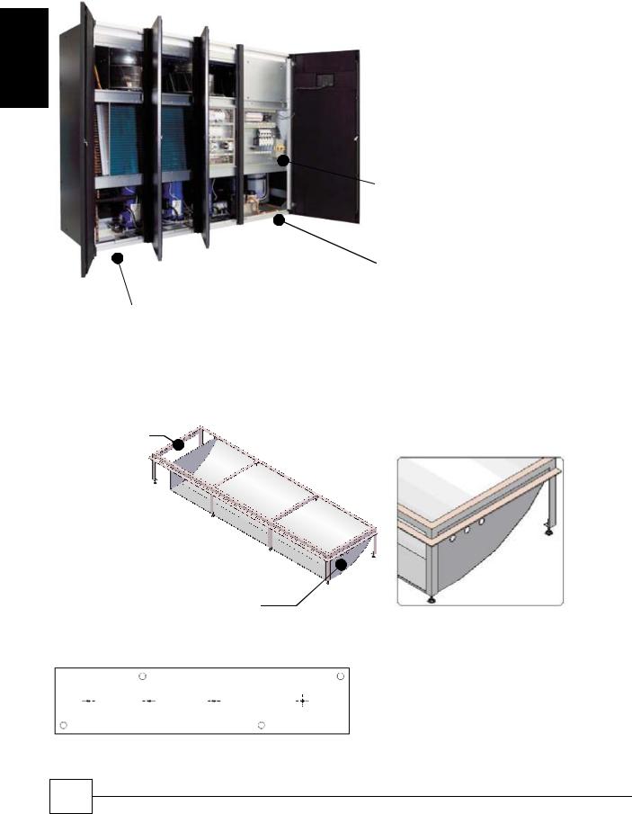
Electrical Services Incoming Cable
Service connections to the smartcool unit are from the left hand side. Provision must be made when sizing cable lengths.
Installation
Mains Electrical Incoming Isolator Termination
Electrical Services Entry Option 2
Mechanical Services Entry + Electrical Option 1
The Floorstand provided by Airedale however has provision for cable entry via the right hand side should it be required, adjacent to the condensate drain.
Option 1
Option 2
Electrical services through floor stand (Next to condensate drain)
Incoming Mains Gland Plate
|
|
|
|
4 hole centres are punched in the gland plate for |
|
|
|
|
|
location of cable glands. The plate is removable for |
|
|
|
|
|
drilling to required size. |
|
1 |
2 |
3 |
4 |
Holes1 and 2 for interconnecting wiring to Outdoor unit. |
|
Holes 3 and 4 for Mains incoming Supply A and B |
|||||
|
|
|
|
14
Precision Air Conditioning
Installation, Maintenance and Commissioning Manual :6877419 02/2013
Precision Air Conditioning |
|
|
|
SmartCoolTM – D |
|
||||||||
Weights |
|
|
|
|
|
|
|
|
|
|
|
|
|
|
|
|
|
|
|
|
|
|
|
|
|
|
|
|
|
|
Unit |
|
|
Shipped Weight (kg) |
|
|
Installed Weight (kg) |
|
|
|
|
|
|
|
|
|
|
|
|
|
|
|
|
|
s |
|
|
|
|
|
|
|
|
|
|
|
|
|
nI |
|
|
|
|
|
|
|
|
|
|
|
|
|
|
|
|
|
SC19D055-X2X2-0 |
|
900 |
|
900 |
|
|
|
|
||
|
X2X2 |
|
SC19D070-X2X2-0 |
|
900 |
|
910 |
|
|
|
|
||
|
|
SC19D080-X2X2-0 |
|
900 |
|
910 |
|
|
|
|
|||
|
|
|
|
|
|
|
|
|
|||||
|
|
|
SC25D080-X2X2-0 |
|
|
1020 |
|
|
1020 |
|
|
|
|
|
|
|
SC25D090-X2X2-0 |
|
|
1110 |
|
|
1120 |
|
|
|
|
|
|
|
|
|
|
|
|
|
|
|
|||
|
|
|
SC25D100-X2X2-0 |
|
|
1130 |
|
|
1130 |
|
|
|
|
|
|
|
SC31D100-X2X2-0 |
|
1280 |
|
1290 |
|
|
|
|
||
|
|
|
SC31D120-X2X2-0 |
|
1300 |
|
1310 |
|
|
|
|
||
|
|
|
SC31D130-X2X2-0 |
|
1300 |
|
1310 |
|
|
|
|
||
|
|
|
|
|
|
|
|
|
|
|
|
||
|
|
|
Unit |
|
|
Shipped Weight (kg) |
|
|
Installed Weight (kg) |
|
|
||
|
|
|
|
|
|
|
|
|
|
|
|
|
|
|
|
|
SC19D033-X2C0-0 |
|
820 |
|
860 |
|
|
|
|
||
|
|
|
SC19D038-X2C0-0 |
|
820 |
|
860 |
|
|
|
|
||
|
|
|
SC19D045-X2C0-0 |
|
820 |
|
860 |
|
|
|
|
||
|
|
|
SC19D064-X2C0-0 |
|
|
890 |
|
920 |
|
|
|
|
|
|
|
|
SC19D070-X2C0-0 |
|
|
900 |
|
930 |
|
|
|
|
|
|
X2C0 |
|
SC19D076-X2C0-0 |
|
|
900 |
|
930 |
|
|
|
|
|
|
|
SC25D045-X2C0-0 |
|
940 |
|
980 |
|
|
|
|
|||
|
|
SC25D050-X2C0-0 |
|
990 |
|
1030 |
|
|
|
|
|||
|
|
SC25D055-X2C0-0 |
|
1000 |
|
1040 |
|
|
|
|
|||
|
|
|
SC25D067-X2C0-0 |
|
|
1010 |
|
1050 |
|
|
|
|
|
|
|
|
SC25D073-X2C0-0 |
|
|
1010 |
|
1060 |
|
|
|
|
|
|
|
|
SC25D080-X2C0-0 |
|
|
1020 |
|
1060 |
|
|
|
|
|
|
|
|
SC31D055-X2C0-0 |
|
1150 |
|
1200 |
|
|
|
|
||
|
|
|
SC31D065-X2C0-0 |
|
1150 |
|
1210 |
|
|
|
|
||
|
|
|
SC31D075-X2C0-0 |
|
1160 |
|
1210 |
|
|
|
|
||
|
|
|
SC31D077-X2C0-0 |
|
|
1170 |
|
1220 |
|
|
|
|
|
|
|
|
SC31D080-X2C0-0 |
|
|
1170 |
|
1220 |
|
|
|
|
|
|
|
|
SC31D083-X2C0-0 |
|
|
1170 |
|
1220 |
|
|
|
|
|
Note
(1)Shipped weights
(2)Installed weight includes refrigerant charges/ internal water volume.
Precision Air Conditioning |
15 |
|
Installation, Maintenance and Commissioning Manual :6877419 02/2013 |
||
|

|
SmartCoolTM - D |
|
Precision Air Conditioning |
|||||||||
|
Weights |
|
|
|
|
|
|
|
|
|
|
|
|
|
|
|
|
|
|
|
|
|
|
|
|
|
|
|
|
Unit |
|
|
Shipped Weight (kg) |
|
|
Installed Weight (kg) |
|
|
Installation |
|
W2W2 |
|
|
|
|
|
|
|
|||
|
|
|
|
|
|
|
|
|
|
|
||
|
|
SC19D055-W2W2-0 |
940 |
|
940 |
|
|
|||||
|
|
|
|
|
|
|
||||||
|
|
|
|
SC19D070-W2W2-0 |
970 |
|
980 |
|
|
|||
|
|
|
|
SC19D080-W2W2-0 |
970 |
|
980 |
|
|
|||
|
|
|
|
SC25D080-W2W2-0 |
|
|
1090 |
|
|
1110 |
|
|
|
|
|
|
SC25D090-W2W2-0 |
|
|
1220 |
|
|
1230 |
|
|
|
|
|
|
|
|
|
|
|
|
|||
|
|
|
|
SC25D100-W2W2-0 |
|
|
1230 |
|
|
1250 |
|
|
|
|
|
|
SC31D100-W2W2-0 |
1390 |
|
1400 |
|
|
|||
|
|
|
|
SC31D120-W2W2-0 |
1400 |
|
1410 |
|
|
|||
|
|
|
|
SC31D130-W2W2-0 |
1400 |
|
1420 |
|
|
|||
|
|
|
|
|
|
|
|
|
|
|||
|
|
|
|
Unit |
|
|
Shipped Weight (kg) |
|
|
Installed Weight (kg) |
|
|
|
|
|
|
|
|
|
|
|
|
|
|
|
|
|
|
|
SC19D033-W2C0-0 |
850 |
|
880 |
|
|
|||
|
|
|
|
SC19D038-W2C0-0 |
860 |
|
890 |
|
|
|||
|
|
|
|
SC19D045-W2C0-0 |
860 |
|
890 |
|
|
|||
|
|
|
|
SC19D064-W2C0-0 |
|
|
950 |
|
|
980 |
|
|
|
|
|
|
SC19D070-W2C0-0 |
|
|
950 |
|
|
980 |
|
|
|
|
W2C0 |
|
SC19D076-W2C0-0 |
|
|
960 |
|
|
990 |
|
|
|
|
|
SC25D045-W2C0-0 |
980 |
|
1020 |
|
|
||||
|
|
|
SC25D050-W2C0-0 |
1050 |
|
1090 |
|
|
||||
|
|
|
SC25D055-W2C0-0 |
1050 |
|
1100 |
|
|
||||
|
|
|
|
SC25D067-W2C0-0 |
|
|
1070 |
|
|
1110 |
|
|
|
|
|
|
SC25D073-W2C0-0 |
|
|
1070 |
|
|
1120 |
|
|
|
|
|
|
SC25D080-W2C0-0 |
|
|
1080 |
|
|
1120 |
|
|
|
|
|
|
SC31D055-W2C0-0 |
1210 |
|
1260 |
|
|
|||
|
|
|
|
SC31D065-W2C0-0 |
1220 |
|
1270 |
|
|
|||
|
|
|
|
SC31D075-W2C0-0 |
1220 |
|
1270 |
|
|
|||
|
|
|
|
SC31D077-W2C0-0 |
|
|
1230 |
|
|
1280 |
|
|
|
|
|
|
SC31D080-W2C0-0 |
|
|
1230 |
|
|
1280 |
|
|
|
|
|
|
SC31D083-W2C0-0 |
|
|
1230 |
|
|
1290 |
|
|
Note
(1)Shipped weights
(2)Installed weight includes refrigerant charges/ internal water volume.
16
Precision Air Conditioning
Installation, Maintenance and Commissioning Manual :6877419 02/2013
Precision Air Conditioning |
|
|
SmartCoolTM – D |
|
|||||||
Weights |
|
|
|
|
|
|
|
|
|
|
|
|
|
|
Unit |
|
Shipped Weight (kg) |
Installed Weight (kg) |
|
|
|
||
|
|
|
|
|
|
|
|
|
|
|
|
|
|
|
SC19D033-W2F0-0 |
|
850 |
|
880 |
|
|
|
nI s |
|
|
|
SC19D038-W2F0-0 |
|
860 |
|
890 |
|
|
|
|
|
|
|
SC19D045-W2F0-0 |
|
860 |
|
890 |
|
|
|
|
|
|
|
SC19D064-W2F0-0 |
|
950 |
|
980 |
|
|
|
|
|
|
|
SC19D070-W2F0-0 |
|
950 |
|
980 |
|
|
|
|
|
W2F0 |
|
SC19D076-W2F0-0 |
|
960 |
|
990 |
|
|
|
|
|
|
SC25D045-W2F0-0 |
|
980 |
|
1020 |
|
|
|
|
|
|
|
|
|
|
|
|
|
||||
|
|
SC25D050-W2F0-0 |
|
1050 |
|
1090 |
|
|
|
|
|
|
|
SC25D055-W2F0-0 |
|
1050 |
|
1100 |
|
|
|
|
|
|
|
|
SC25D067-W2F0-0 |
|
1070 |
|
1110 |
|
|
|
|
|
|
|
SC25D073-W2F0-0 |
|
1070 |
|
1120 |
|
|
|
|
|
|
|
SC25D080-W2F0-0 |
|
1080 |
|
1120 |
|
|
|
|
|
|
|
SC31D055-W2F0-0 |
|
1210 |
|
1260 |
|
|
|
|
|
|
|
SC31D065-W2F0-0 |
|
1220 |
|
1270 |
|
|
|
|
|
|
|
SC31D075-W2F0-0 |
|
1220 |
|
1270 |
|
|
|
|
|
|
|
SC31D077-W2F0-0 |
|
1230 |
|
1280 |
|
|
|
|
|
|
|
SC31D080-W2F0-0 |
|
1230 |
|
1280 |
|
|
|
|
|
|
|
SC31D083-W2F0-0 |
|
1230 |
|
1290 |
|
|
|
|
|
|
|
|
|
|
|
|
|
|
|
|
|
|
|
Unit |
|
Shipped Weight (kg) |
|
Installed Weight (kg) |
|
|
|
|
|
|
|
|
|
|
|
|
|
|
|
|
|
|
|
SC19D065-C000-0 |
|
725 |
|
780 |
|
|
|
|
|
C000 |
|
SC19D075-C000-0 |
|
725 |
|
780 |
|
|
|
|
|
|
SC19D090-C000-0 |
|
730 |
|
780 |
|
|
|
|
|
|
|
|
|
|
|
|
|
|
|||
|
|
|
SC25D090-C000-0 |
|
840 |
|
920 |
|
|
|
|
|
|
|
SC25D100-C000-0 |
|
840 |
|
920 |
|
|
|
|
|
|
|
SC25D110-C000-0 |
|
840 |
|
920 |
|
|
|
|
|
|
|
SC31D110-C000-0 |
|
1000 |
|
1080 |
|
|
|
|
|
|
|
SC31D130-C000-0 |
|
1000 |
|
1080 |
|
|
|
|
|
|
|
SC31D150-C000-0 |
|
1000 |
|
1080 |
|
|
|
|
|
|
|
|
|
|
|
|
|
|||
|
|
|
Unit |
|
Shipped Weight (kg) |
Installed Weight (kg) |
|
|
|||
|
|
|
|
|
|
|
|
|
|
|
|
|
|
|
SC19D033-C0C0-0 |
|
730 |
|
790 |
|
|
|
|
|
C0C0 |
|
SC19D038-C0C0-0 |
|
730 |
|
790 |
|
|
|
|
|
|
SC19D045-C0C0-0 |
|
730 |
|
790 |
|
|
|
|
|
|
|
|
|
|
|
|
|
|
|||
|
|
|
SC25D045-C0C0-0 |
|
850 |
|
930 |
|
|
|
|
|
|
|
SC25D050-C0C0-0 |
|
850 |
|
930 |
|
|
|
|
|
|
|
SC25D055-C0C0-0 |
|
850 |
|
930 |
|
|
|
|
|
|
|
SC31D055-C0C0-0 |
|
1010 |
|
1100 |
|
|
|
|
|
|
|
SC31D065-C0C0-0 |
|
1010 |
|
1100 |
|
|
|
|
|
|
|
SC31D075-C0C0-0 |
|
1010 |
|
1100 |
|
|
|
|
|
Note |
|
|
|
|
|
|
|
|
|
|
(1)Shipped weights
(2)Installed weight includes refrigerant charges/ internal water volumes.
Precision Air Conditioning |
17 |
|
Installation, Maintenance and Commissioning Manual :6877419 02/2013 |
||
|
SmartCoolTM - D |
Precision Air Conditioning |
Refrigerant Pipe Sizing Guide
The refrigerant pipe sizing information below is for a guide only. Pipe sizes based on 100% load.
|
|
|
|
|
|
|
|
|
|
|
|
|
|
|
|
|
|
|
|
|
Equivalent Pipe Lengths with R410A |
|
|
|
||||||
Installation |
|
|
Indoor |
|
Outdoor |
|
Indoor Unit |
|
|
|
|
|
|
|
|
|
|
|
|
|
|
|
|
|
||||||
|
|
Unit |
|
Unit |
|
Connection Size |
|
0-15m |
|
Discharge |
|
15-40m |
|
|
Discharge |
|||||||||||||||
|
|
|
|
|
|
|
|
|
|
|
|
|
|
Liquid |
|
Horizontal |
|
Vertical |
|
Liquid |
|
Horizontal |
|
Vertical |
||||||
|
|
|
|
|
|
|
|
|
Liquid |
|
Disch |
(3) |
|
(1) |
|
(2) |
|
(3) |
|
(1) |
(2) |
|
||||||||
|
|
|
SC19D055-X2X2-0 |
|
CR50 |
1/2" |
|
7/8" |
|
5/8" |
|
7/8" |
|
3/4" |
|
5/8" |
|
7/8" |
7/8" |
|
||||||||||
|
|
|
SC19D070-X2X2-0 |
|
|
CR65 |
|
|
5/8" |
|
|
7/8" |
|
|
5/8" |
|
|
7/8" |
|
|
7/8" |
|
|
5/8" |
|
|
7/8" |
|
7/8" |
|
|
|
|
SC19D080-X2X2-0 |
|
CR65 |
5/8" |
|
7/8" |
|
5/8" |
|
7/8" |
|
7/8" |
|
3/4" |
|
7/8" |
7/8" |
|
||||||||||
|
|
|
SC25D080-X2X2-0 |
|
|
CR65 |
|
|
5/8" |
|
|
7/8" |
|
|
5/8" |
|
|
7/8" |
|
|
7/8" |
|
|
3/4" |
|
|
7/8" |
|
7/8" |
|
|
|
|
SC25D090-X2X2-0 |
|
CR65 |
7/8" |
|
1 1/8" |
|
5/8" |
|
7/8" |
|
7/8" |
|
3/4" |
|
7/8" |
7/8" |
|
||||||||||
|
|
|
SC25D100-X2X2-0 |
|
|
CR80 |
|
|
7/8" |
|
|
1 1/8" |
|
|
3/4" |
|
|
1 1/8" |
|
|
1 1/8" |
|
|
3/4" |
|
|
1 1/8" |
|
1 1/8" |
|
|
|
|
|
|
|
|
|
|
|
|
|
|
|
|
|
|
|
|
|
|
||||||||||
|
|
|
SC31D100-X2X2-0 |
|
CR80 |
7/8" |
|
1 1/8" |
|
3/4" |
|
1 1/8" |
|
1 1/8" |
|
3/4" |
|
1 1/8" |
1 1/8" |
|
||||||||||
|
|
|
SC31D120-X2X2-0 |
|
|
CR105 |
|
|
7/8" |
|
|
1 1/8" |
|
|
3/4" |
|
|
1 1/8" |
|
|
1 1/8" |
|
|
3/4" |
|
|
1 1/8" |
|
1 1/8" |
|
|
|
|
SC31D130-X2X2-0 |
|
CR105 |
7/8" |
|
1 1/8" |
|
3/4" |
|
1 1/8" |
|
1 1/8" |
|
7/8" |
|
1 1/8" |
1 1/8" |
|
||||||||||
|
|
|
SC19D033-X2C0-0 |
|
|
CR50 |
|
|
1/2" |
|
|
7/8" |
|
|
5/8" |
|
|
7/8" |
|
|
3/4" |
|
|
5/8" |
|
|
7/8" |
|
7/8" |
|
|
|
|
SC19D038-X2C0-0 |
|
CR65 |
5/8" |
|
7/8" |
|
5/8" |
|
7/8" |
|
7/8" |
|
5/8" |
|
7/8" |
7/8" |
|
||||||||||
|
|
|
SC19D045-X2C0-0 |
|
|
CR65 |
|
|
5/8" |
|
|
7/8" |
|
|
5/8" |
|
|
7/8" |
|
|
7/8" |
|
|
3/4" |
|
|
7/8" |
|
7/8" |
|
|
|
|
SC19D064-X2C0-0 |
|
CR105 |
5/8" |
|
7/8" |
|
|
3/4” |
|
1 1/8” |
|
1 1/8” |
|
7/8” |
|
1 3/8” |
|
1 1/8” |
|||||||||
|
|
|
SC19D070-X2C0-0 |
|
|
CR105 |
|
|
7/8" |
|
|
1 1/8" |
|
|
3/4” |
|
|
1 1/8” |
|
|
1 1/8” |
|
|
7/8” |
|
|
1 3/8” |
|
1 1/8” |
|
|
|
|
SC19D076-X2C0-0 |
|
CR105 |
7/8" |
|
1 1/8" |
|
|
3/4” |
|
1 1/8” |
|
1 1/8” |
|
7/8” |
|
1 3/8” |
|
1 1/8” |
|||||||||
|
|
|
SC25D045-X2C0-0 |
|
|
CR65 |
|
|
7/8" |
|
|
1 1/8" |
|
|
5/8" |
|
|
7/8" |
|
|
7/8" |
|
|
3/4" |
|
|
7/8" |
|
7/8" |
|
|
|
|
SC25D050-X2C0-0 |
|
CR65 |
7/8" |
|
1 1/8" |
|
5/8" |
|
7/8" |
|
7/8" |
|
3/4" |
|
7/8" |
7/8" |
|
||||||||||
|
|
|
SC25D055-X2C0-0 |
|
|
CR80 |
|
|
7/8" |
|
|
1 1/8" |
|
|
3/4" |
|
|
1 1/8" |
|
|
1 1/8" |
|
|
3/4" |
|
|
1 1/8" |
|
1 1/8" |
|
|
|
|
SC25D067-X2C0-0 |
|
CR105 |
7/8" |
|
1 3/8" |
|
|
3/4” |
|
1 1/8” |
|
1 1/8” |
|
7/8” |
|
1 3/8” |
|
1 1/8” |
|||||||||
|
|
|
SC25D073-X2C0-0 |
|
|
CR105 |
|
|
7/8" |
|
|
1 3/8" |
|
|
3/4” |
|
|
1 1/8” |
|
|
1 1/8” |
|
|
7/8” |
|
|
1 3/8” |
|
1 1/8” |
|
|
|
|
SC25D080-X2C0-0 |
|
CR105 |
7/8" |
|
1 3/8" |
|
|
3/4” |
|
1 1/8” |
|
1 1/8” |
|
7/8” |
|
1 3/8” |
|
1 1/8” |
|||||||||
|
|
|
SC31D055-X2C0-0 |
|
|
CR80 |
|
|
7/8" |
|
|
1 3/8" |
|
|
3/4" |
|
|
1 1/8" |
|
|
1 1/8" |
|
|
3/4" |
|
|
1 1/8" |
|
1 1/8" |
|
|
|
|
SC31D065-X2C0-0 |
|
CR105 |
7/8" |
|
1 3/8" |
|
3/4" |
|
1 1/8" |
|
1 1/8" |
|
3/4" |
|
1 1/8" |
1 1/8" |
|
||||||||||
|
|
|
SC31D075-X2C0-0 |
|
|
CR105 |
|
|
7/8" |
|
|
1 3/8" |
|
|
3/4" |
|
|
1 1/8" |
|
|
1 1/8" |
|
|
7/8" |
|
|
1 1/8" |
|
1 1/8" |
|
|
|
|
SC31D077-X2C0-0 |
|
CR105 |
7/8" |
|
1 3/8" |
|
|
3/4” |
|
1 1/8” |
|
1 1/8” |
|
7/8” |
|
1 3/8” |
|
1 1/8” |
|||||||||
|
|
|
SC31D080-X2C0-0 |
|
|
CR105 |
|
|
7/8" |
|
|
1 3/8" |
|
|
3/4” |
|
|
1 1/8” |
|
|
1 1/8” |
|
|
7/8” |
|
|
1 3/8” |
|
1 1/8” |
|
|
|
|
SC31D083-X2C0-0 |
|
CR105 |
7/8" |
|
1 3/8" |
|
|
3/4” |
|
1 1/8” |
|
1 1/8” |
|
7/8” |
|
1 3/8” |
|
1 1/8” |
|||||||||
(1)For interconnecting pipework with a predominantly horizontal layout.
(2)For interconnecting pipework with a predominantly vertical layout.
(3)Careful pipework selection must be done if the liquid line rises. Additional system sub cooling may be required to overcome friction losses.
IMPORTANT |
Tandem Compressor and suction throttle valve applications: |
|
In part load, gas velocity should be taken into account when selecting and commissioning |
|
pipework to ensure full oil return. |
REMEMBER excessive pressure loss in interconnecting pipework will impair system performance; this should be factored in during the design of the system and where necessary oil separators employed.
Excessive pressure drop in liquid lines can cause poor refrigerant distribution to expansion devices and can cause malfunction of the system (especially with condensers lower than the evaporator)
Oil Traps |
For long vertical rises in both liquid and discharge lines, it is essential that oil traps are |
|
located every 4m to ensure proper oil movement / entrapment. In addition there should be |
|
an oil trap at the exit of the air handling unit before a vertical riser is applied (refer to |
|
example below). |
Pipe Supports |
The following table identifies the maximum |
|
distance between pipe supports on vertical |
|
and horizontal pipe runs. |
Pipe O/D (inches) |
Support distance (m) |
3/8 - 7/8 |
1.0 |
1 1/8 - 2 1/8 |
2.0 |
CAUTION |
All pipework should be clamped prior to insulation being applied. Clamping over |
|
insulation is not acceptable. |
Horizontal Sections |
It is good practice to ensure a slight gradient toward the compressor in the direction of the |
|
refrigerant flow for suction lines running horizontal. This assists oil return to the |
|
compressor. A gradient of approximately 1:200 (0.5%) shall be used. |
18
Precision Air Conditioning
Installation, Maintenance and Commissioning Manual :6877419 02/2013

Precision Air Conditioning |
SmartCoolTM – D |
||||||||
Liquid Line |
If the system is configured with the SmartCool higher than the condenser unit h it may |
||||||||
|
|
|
be required to increase the degree of sub cooling to prevent flashing gas. This flashing is |
||||||
|
|
|
caused by excess pressure drop caused by the static head of refrigerant and can cause |
||||||
|
|
|
poor operation of the evaporator and metering device. |
||||||
|
|
|
Careful pipe sizing is recommended to ensure that the liquid does not form gas due to |
||||||
|
|
|
excess pressure drop |
|
|
|
|
|
|
|
|
|
Increasing the liquid line size minimizes pipe friction and flashing due to friction pressure |
||||||
|
|
|
drop. |
|
|
|
|
|
|
|
|
|
However as a fail safe it is recommended that the condenser is installed below the |
||||||
|
|
|
indoor unit to allow for correct liquid drain. |
||||||
Pipe Insulation |
The liquid line of the system must be insulated if passing through extremely warm places |
||||||||
|
|
|
(Boiler houses etc). Ensuring that the refrigerant does not become flash gas. |
||||||
Condenser above Air Handling Unit |
Condenser below Air Handling Unit |
||||||||
|
|
|
|
|
|
|
|
|
|
|
|
|
|
|
|
|
|
|
|
|
|
|
|
|
|
|
|
|
|
|
|
|
|
|
|
|
|
|
|
|
|
|
|
|
|
|
|
|
|
|
|
|
|
|
|
|
|
|
|
nI s
Warning: May have flash gas occurring in liquid line if riser friction losses are excessive.
Discharge Line |
Liquid |
Diagrams above for illustration only |
Refrigerant Charging Guide
The following information can be used to estimate the refrigerant quantity required in a typical split system installation.
Unit Refrigerant Charge The following table shows the refrigerant charge / circuit for the indoor and outdoor units.
(kg/Circuit)
Indoor Unit |
HGRH(1) |
Standard Condenser |
Larger Condenser |
|||
|
|
|
|
|
|
|
(Indoor Unit) |
kg/Circuit |
kg/Circuit |
(Outdoor Unit) |
kg/Circuit |
(Outdoor Unit) |
kg/Circuit |
SC19D055-X2X2 |
4.41 |
4.56 |
CR50 |
4.9 |
CR65 |
9.78 |
SC19D070-X2X2 |
4.66 |
4.81 |
CR65 |
9.78 |
CR80 |
8.37 |
SC19D080-X2X2 |
4.66 |
4.81 |
CR65 |
9.78 |
CR80 |
8.37 |
SC25D080-X2X2 |
5.84 |
6.04 |
CR65 |
9.78 |
CR80 |
8.37 |
SC25D090-X2X2 |
6.37 |
6.60 |
CR65 |
9.78 |
CR80 |
8.37 |
SC25D100-X2X2 |
6.38 |
6.60 |
CR80 |
8.37 |
CR105 |
16.72 |
SC31D100-X2X2 |
7.56 |
7.83 |
CR80 |
8.37 |
CR105 |
16.72 |
SC31D120-X2X2 |
7.57 |
7.83 |
CR105 |
16.72 |
CR130 |
22.05 |
SC31D130-X2X2 |
7.67 |
7.94 |
CR105 |
16.72 |
CR130 |
22.05 |
SC19D033-X2C0 |
4.34 |
4.49 |
CR50 |
4.9 |
CR65 |
9.78 |
SC19D038-X2C0 |
4.59 |
4.74 |
CR65 |
9.78 |
CR80 |
8.37 |
SC19D045-X2C0 |
4.59 |
4.74 |
CR65 |
9.78 |
CR80 |
8.37 |
SC19D064-X2C0 |
5.13 |
5.33 |
CR105 |
16.72 |
CR130 |
22.05 |
SC19D070-X2C0 |
5.13 |
5.34 |
CR105 |
16.72 |
CR130 |
22.05 |
SC19D076-X2C0 |
5.14 |
5.34 |
CR105 |
16.72 |
CR130 |
22.05 |
SC25D045-X2C0 |
5.77 |
5.97 |
CR65 |
9.78 |
CR80 |
8.37 |
SC25D050-X2C0 |
6.31 |
6.53 |
CR65 |
8.37 |
CR80 |
8.37 |
SC25D055-X2C0 |
6.31 |
6.53 |
CR80 |
8.37 |
CR105 |
16.72 |
SC25D067-X2C0 |
6.31 |
6.56 |
CR105 |
16.72 |
CR130 |
22.05 |
SC25D073-X2C0 |
6.32 |
6.57 |
CR105 |
16.72 |
CR130 |
22.05 |
SC25D080-X2C0 |
6.32 |
6.57 |
CR105 |
16.72 |
CR130 |
22.05 |
SC31D055-X2C0 |
7.49 |
7.75 |
CR80 |
8.37 |
CR105 |
16.72 |
SC31D065-X2C0 |
7.49 |
7.76 |
CR105 |
16.72 |
CR130 |
22.05 |
SC31D075-X2C0 |
7.49 |
7.76 |
CR105 |
16.72 |
CR130 |
22.05 |
SC31D077-X2C0 |
7.50 |
7.79 |
CR105 |
16.72 |
CR130 |
22.05 |
SC31D080-X2C0 |
7.50 |
7.79 |
CR105 |
16.72 |
CR130 |
22.05 |
SC31D083-X2C0 |
7.50 |
7.79 |
CR105 |
16.72 |
CR130 |
22.05 |
(1)Fitted with optional hot gas re-heat
Precision Air Conditioning |
19 |
|
Installation, Maintenance and Commissioning Manual :6877419 02/2013 |
||
|
Installation
SmartCoolTM - D |
Precision Air Conditioning |
||
Liquid Line Refrigerant |
The following table shows the refrigerant charge / metre for the liquid line, using R410A |
||
Charge (kg/m) |
and assuming a liquid line temperature of 40°C. |
||
|
|
|
|
|
Liquid Line (m) |
kg/m |
|
|
3/8” |
0.05 |
|
|
1/2” |
0.09 |
|
|
5/8” |
0.15 |
|
|
3/4” |
0.21 |
|
|
7/8” |
0.30 |
|
|
1 1/8” |
0.53 |
|
IMPORTANT
Calculation of Liquid Line
Refrigerant Charge (kg)
The pipe sizes/refrigerant charges quoted are for guidance only. It is the responsibility of the installing contractor/site engineer to check the pipe sizes/refrigerant charges are correct for each system installation and application. Excess pressure drop on a system may require additional refrigerant charges to ensure correct unit operation.
Split systems may require additional oil which should be added to the low side of each compressor.
Design should be in accordance with accepted refrigeration practice to ensure good oil return to the compressor(s) under all normal operating conditions.
The liquid line refrigerant charge can be calculated using the following equation:
LR = L x m |
Where: |
||
|
LR |
= Total Liquid Line Refrigerant charge (kg) |
|
|
L |
= |
Length of Interconnecting pipework (metres) |
|
m |
= |
Liquid Line Refrigerant charge / metre. Refer to |
|
|
|
Liquid Line Refrigerant |
Charge (kg/m), above.
Calculation of System |
The system refrigerant charge can be calculated using the following equation: |
|||
Refrigerant Charge (kg) |
|
Where: |
||
SR = LR + IR + OR |
||||
|
||||
|
|
SR |
= Total System Refrigerant charge (kg) |
|
|
|
|||
|
|
LR |
= Total Liquid Line Refrigerant charge. (As calculated from above) |
|
|
|
IR |
= Indoor Unit Refrigerant Charge. |
|
|
|
OR |
= Outdoor Unit Refrigerant Charge. |
|
Example |
Indoor Unit Model Ref. |
= SC19D055-X2X2-0 |
|
Outdoor Unit Model Ref. |
= CR50 Condenser |
|
Interconnecting Pipework |
= 10 metres |
Selecting The Liquid Line Size From the Refrigerant Pipe Sizing Guide, the liquid line size given for pipework length of 10 metres is:
Liquid Line Size |
= 5/8” |
Liquid Line Refrigerant |
LR = L x m |
Charge |
|
|
|
|
LR = 10 x 0.15 |
System Refrigerant Charge |
|
SR = LR + IR + OR |
Where:
L |
= 10 metres |
m |
= 0.15 kg/m |
Liquid Line Charge = 1.5 kg |
|
Where: |
|
LR |
= 1.5 kg. (As calculated from above) |
IR |
= 4.41 kg |
OR |
= 4.9 kg |
SR = 1.5 + 5.57 + 4.9 System Refrigerant Charge = 10.81kg / Circuit
20
Precision Air Conditioning
Installation, Maintenance and Commissioning Manual :6877419 02/2013
Precision Air Conditioning |
SmartCoolTM – D |
|
Liquid Sub Cooling |
The degree of liquid sub cooling required to prevent flashing of liquid refrigerant can be calculated by |
|
|
the following method. |
|
Given the following as an example:
∙Refrigerant R410A
∙Condensing temperature (54.4°C)
∙Liquid lift 20m
∙Piping friction loss 0.21 bar
∙Losses through valves and fittings 0.5 Bar
1.Determine the pressure drop due to pipe friction = 0.21 Bar
2.Pressure drop due to valves and fittings = 0.5 Bar
3.Pressure loss due to liquid lift = height x 0.115 = 20 x 0.115 = 2.3 bar
Note:- At normal liquid temperatures the static pressure loss due to elevation at the top of a liquid lift 0.115 bar/m
Therefore:- Total pressure loss in liquid line = 3.01bar
Condensing pressure @ Condensing temperature (54.4°C) = 34 Bar
Total pressure loss in liquid line = 3.01 Bar
Nett pressure at Expansion valve = 34 - 3.01 = 30.99 bar
Saturation temperature at the Nett pressure at expansion valve (30.99 bar) = 52°C (from Refrigerant tables)
Sub cooling required
=Condensing temperature — Saturation temperature at the Nett pressure at expansion valve
=54.4 - 52 = 2.4 °C
Therefore liquid sub cooling required to prevent liquid flashing = 2.4 °C
Packaged Unit Pre-Charged Refrigerant Volumes
Indoor unit |
kg / circuit |
HGRH kg / circuit |
SC19D055-W2W2 |
5.75 |
5.90 |
SC19D070-W2W2 |
7.32 |
7.47 |
SC19D080-W2W2 |
7.32 |
7.47 |
SC25D080-W2W2 |
8.51 |
8.70 |
SC25D090-W2W2 |
10.85 |
11.07 |
SC25D100-W2W2 |
10.85 |
11.07 |
SC31D100-W2W2 |
12.04 |
12.30 |
SC31D120-W2W2 |
12.04 |
12.30 |
SC31D130-W2W2 |
12.04 |
12.31 |
SC19D033-W2C0 |
5.68 |
5.83 |
SC19D038-W2C0 |
7.25 |
7.40 |
SC19D045-W2C0 |
7.25 |
7.40 |
SC19D064-W2C0 |
9.60 |
9.81 |
SC19D070-W2C0 |
9.61 |
9.81 |
SC19D076-W2C0 |
9.61 |
9.82 |
SC25D045-W2C0 |
8.44 |
8.63 |
SC25D050-W2C0 |
10.78 |
11.00 |
SC25D055-W2C0 |
10.78 |
11.00 |
SC25D067-W2C0 |
10.79 |
11.04 |
SC25D073-W2C0 |
10.79 |
11.04 |
SC25D080-W2C0 |
10.80 |
11.04 |
SC31D055-W2C0 |
11.96 |
12.23 |
SC31D065-W2C0 |
11.97 |
12.23 |
SC31D075-W2C0 |
11.97 |
12.23 |
SC31D077-W2C0 |
11.97 |
12.26 |
SC31D080-W2C0 |
11.98 |
12.27 |
SC31D083-W2C0 |
11.98 |
12.27 |
(1)Fitted with optional hot gas re-heat
Indoor unit |
kg / circuit |
HGRH kg / circuit |
SC19D033-W2F0 |
5.68 |
5.83 |
SC19D038-W2F0 |
7.25 |
7.40 |
SC19D045-W2F0 |
7.25 |
7.40 |
SC19D064-W2F0 |
9.60 |
9.81 |
SC19D070-W2F0 |
9.61 |
9.81 |
SC19D076-W2F0 |
9.61 |
9.82 |
SC25D045-W2F0 |
8.44 |
8.63 |
SC25D050-W2F0 |
10.78 |
11.00 |
SC25D055-W2F0 |
10.78 |
11.00 |
SC25D067-W2F0 |
10.79 |
11.04 |
SC25D073-W2F0 |
10.79 |
11.04 |
SC25D080-W2F0 |
10.80 |
11.04 |
SC31D055-W2F0 |
11.96 |
12.23 |
SC31D065-W2F0 |
11.97 |
12.23 |
SC31D075-W2F0 |
11.97 |
12.23 |
SC31D077-W2F0 |
11.97 |
12.26 |
SC31D080-W2F0 |
11.98 |
12.27 |
SC31D083-W2F0 |
11.98 |
12.27 |
|
|
|
nI s
Precision Air Conditioning |
21 |
|
Installation, Maintenance and Commissioning Manual :6877419 02/2013 |
||
|

SmartCoolTM - D |
Precision Air Conditioning |
nI s
Design Data – Water Cooled & Free Cooling
Dry Cooler (kW) |
The dry cooler design duty is equivalent to the Total Heat of Rejection (THR) from the indoor unit. |
|
This value can be taken from the performance data in the technical manual using the following. |
Parameters required are:
∙Ambient conditions (°C dB) Airedale recommend a 10°C lower than the EWT.
∙Glycol content (%)
∙ Entering & leaving water/glycol temperatures (°C) (EWT and LWT)
∙Mean condensing temperature (°C) Based on 5°C above leaving water/glycol temperature
Calculation of Design |
The maximum design volumetric flow rate can be calculated using the following equation: |
||||
Volumetric Flow Rate (l/s) |
|
|
|
|
|
& |
Q |
|
|
|
|
|
|
|
|
||
|
V = |
|
|
|
|
|
|
ρ x Cp x |
T |
|
|
|
Where: |
= |
Total Heat Rejection (kW). |
||
|
Q |
||||
|
T |
= |
Temperature Difference between Water/Glycol Entering/ Leaving (°C). |
||
|
ρ |
= |
Density. Refer to table below. |
||
|
Cp |
= |
Specific heat capacity. Refer to table below. |
||
Calculation of Indoor Unit
Pressure Drop ( Ps)
The maximum indoor unit pressure drop can be calculated using the following equation:
DPs= DPw x Pχ
Using the volumetric flow rate calculated above, the pressure drop ( Pw) can be taken from the relevant pressure drop graph..
Where: |
|
|
Ps |
= |
Maximum Water/Glycol Pressure Drop for the indoor unit (kPa). |
Pw |
= |
Equivalent Water Pressure Drop for indoor unit (kPa). |
Pχ |
= |
% Glycol Pressure Drop Correction Factor @ 20°C Water Temperature. |
|
|
Refer to table below. |
|
|
The resultant pressure drop ( |
Ps) is the maximum pressure drop based on the indoor unit |
|
|||||||||
|
|
running at the prescribed conditions. |
|
|
|
|
|
|
|||||
|
|
This will typically occur when the water/glycol temperature is approximately 20°C and the |
|
||||||||||
|
|
water/glycol is being circulated through the free cooling coil and through the water cooled |
|
||||||||||
|
|
condenser. |
|
|
|
|
|
|
|
|
|||
|
|
The indoor unit pressure drop will reduce at other operating conditions. |
|
|
|||||||||
Specific Heat Capacity (Cp) |
|
|
|
|
|
|
|
|
|
|
|
|
|
|
Water/Glycol Temperature °C |
|
|
|
|
|
Ethylene Glycol (Volume) / Freezing Point °C |
|
|
||||
|
|
|
|
|
0% / 0°C |
10% / -4°C |
20% / -9°C |
30% / -15°C |
40% / -23°C |
||||
|
|
|
|
|
|
Fχ |
Fχ |
Fχ |
Fχ |
Fχ |
|||
|
|
20 |
|
|
|
4.183 |
|
3.972 |
|
3.815 |
3.645 |
3.468 |
|
|
|
25 |
|
|
|
4.181 |
|
3.981 |
|
3.826 |
3.660 |
3.485 |
|
|
|
30 |
|
|
|
4.179 |
|
3.989 |
|
3.838 |
3.674 |
3.502 |
|
|
|
35 |
|
|
|
4.178 |
|
3.998 |
|
3.849 |
3.688 |
3.518 |
|
|
|
40 |
|
|
|
4.179 |
|
4.007 |
|
3.861 |
3.702 |
3.535 |
|
|
|
45 |
|
|
|
4.181 |
|
4.015 |
|
3.872 |
3.716 |
3.552 |
|
ρ |
|
|
|
|
|
|
|
|
|
|
|
|
|
|
|
|
|
|
|
|
Ethylene Glycol (Volume) / Freezing Point °C |
|
|
||||
Density ( ) |
|
|
|
|
|
|
|
|
|
|
|
|
|
|
|
Water/Glycol Temperature °C |
|
0% / 0°C |
|
10% / -4°C |
|
20% / -9°C |
30% / -15°C |
40% / -23°C |
|||
|
|
|
|
|
|
Fχ |
|
Fχ |
|
Fχ |
Fχ |
Fχ |
|
|
|
20 |
|
|
|
998 |
|
1013 |
|
1030 |
1045 |
1060 |
|
|
|
25 |
|
|
|
997 |
|
1012 |
|
1028 |
1043 |
1058 |
|
|
|
30 |
|
|
|
996 |
|
1010 |
|
1026 |
1041 |
1055 |
|
|
|
35 |
|
|
|
994 |
|
1008 |
|
1024 |
1039 |
1053 |
|
|
|
40 |
|
|
|
992 |
|
1006 |
|
1022 |
1036 |
1050 |
|
|
|
45 |
|
|
|
990 |
|
1003 |
|
1020 |
1035 |
1048 |
|
Pressure Drop Correction |
|
|
|
|
|
|
|
|
|
|
|||
|
Water/Glycol Temperature °C |
|
|
|
|
Ethylene Glycol (Volume) |
|
|
|||||
Factor (Pχ) |
|
|
0% |
|
10% |
|
20% |
30% |
40% |
|
|||
|
|
|
Pχ |
Pχ |
Pχ |
Pχ |
Pχ |
||||||
|
|
|
|
|
|
||||||||
|
|
20 |
|
|
|
0.983 |
|
1.0125 |
|
1.054 |
1.0958 |
1.15 |
|
22
Precision Air Conditioning
Installation, Maintenance and Commissioning Manual :6877419 02/2013

Precision Air Conditioning |
SmartCoolTM – D |
|
Installation Data |
|
|
System Pressure |
The system must be pressure tested to ensure that the pipework is installed satisfactory. |
|
Strength Test
Nitrogen (Oxygen free) should only be used.
Strength Pressure Test is the pressure applied to a refrigeration system for its integral strength and it is usually defined as maximum working pressure (MWP) x factor of 1.43.
The pressure test ideally should be carried out for a period of one hour.
IMPORTANT Low pressure transducers and switches must be removed whilst the high pressure strength test is carried out.
CAUTION |
Before carrying out the pressure test, precautions shall be taken to evacuate all |
|
personnel from the area of risk and post notices advising that the system or |
|
equipment is under pressure. |
|
The test pressure in the system should be held for at least one hour. A longer period may |
|
be appropriate for larger systems or a fall in pressure due to leaks may not be detected. |
|
Any fall in pressure indicates a leak which should be traced. |
System Leak Test |
The system leak test is carried out with the low pressure transducers and switches fitted. |
|
Leak Pressure Test is the pressure applied to a refrigeration system or part of a system to |
|
test for leakage. This test pressure is defined as Maximum Working Pressure of the |
|
particular system x factor of 1.1. |
RECORD |
Record on commissioning sheet provided once completed. |
IMPORTANT It is important that solenoid valves are energised correctly to ensure that the Hot Gas Reheat coil is fully pressure tested (the normally closed (NC) valve should be energised).
The use of a magnetic coil lifter is recommended.
Filter Drier |
The filter drier must be installed as close to the expansion valve as possible. It should be |
|
the last component within the system to be installed. |
IMPORTANT |
Failure to correctly fit a filter drier can cause malfunction of the system. They are |
|
however no substitute to good refrigeration practices with regard to system |
|
cleanliness. |
nI s
Precision Air Conditioning |
23 |
|
Installation, Maintenance and Commissioning Manual :6877419 02/2013 |
||
|
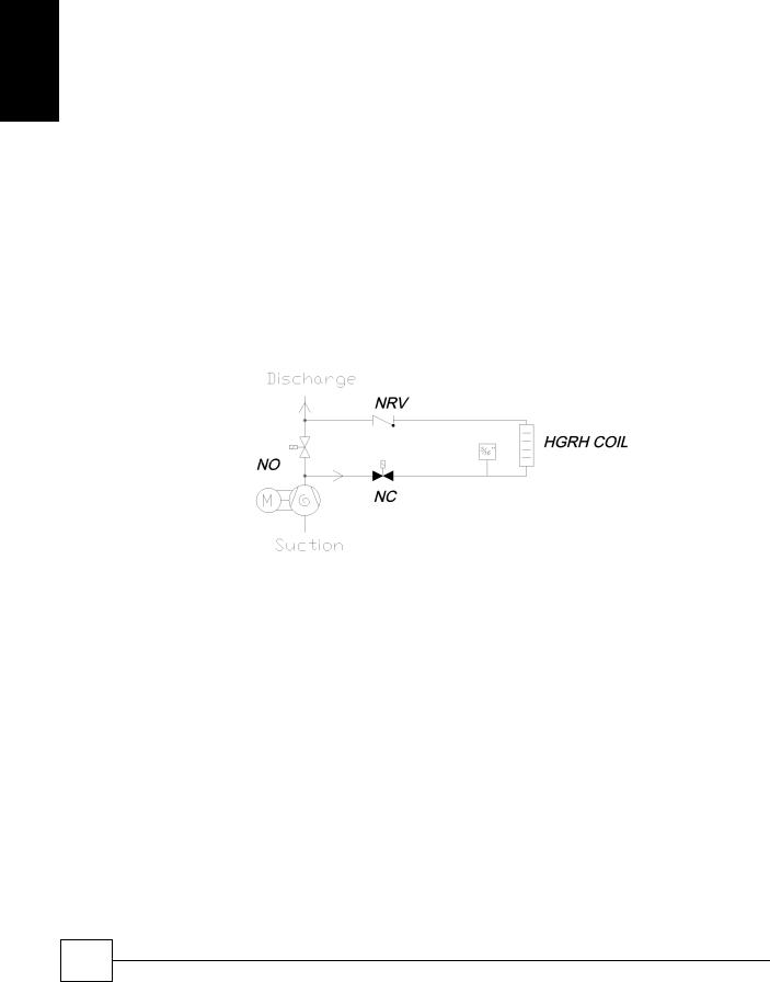
SmartCoolTM - D |
Precision Air Conditioning |
onti nI s
Installation Data
Evacuation |
Evacuation for systems operating on R410A refrigerant should be carried out as follows |
|
|
1 |
The procedure should be carried out using a high vacuum pump. The pump should |
|
|
be connected to the high and low pressure sides of the system via a gauge manifold |
|
|
fitted with compound gauges. A high vacuum gauge should be fitted to the system at |
|
|
the furthest point from the vacuum pump. |
|
2 |
Triple evacuation should be used to ensure that all contaminants are removed or at |
|
|
least reduced to significantly low proportions. |
|
3 |
The vacuum pump should be operated until a pressure of 1.5 Torr (200 Pa) absolute |
|
|
pressure is reached, at which time the vacuum pump should be stopped and the |
|
|
vacuum broken with oxygen free nitrogen until the pressure rises above zero. |
|
4 |
The above operation should be repeated a second time. |
|
5 |
The system should then be evacuated a third time but this time to 0.5 Torr (absolute |
|
|
pressure and broken with the correct refrigerant, until pressures equalise between |
|
|
the charging bottle and the system. |
RECORD  Record on commissioning sheet provided once completed.
IMPORTANT It is important that solenoid valves are energises correctly to ensure that the Hot Gas Reheat Coil is fully evacuated. (The Normally Closed (NC) valve should be energised).
The use of a magnetic coil lifter is recommended.
CAUTION Ensure that the evacuation gauge is isolated before introducing any pressure. The gauge may become dangerous when exposed to any positive pressure.
24
Precision Air Conditioning
Installation, Maintenance and Commissioning Manual :6877419 02/2013
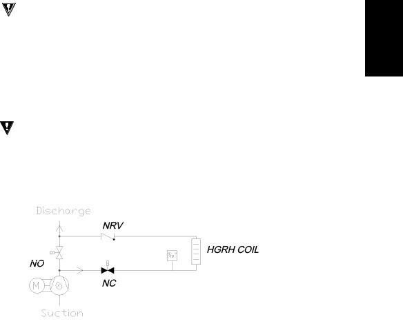
Precision Air Conditioning |
SmartCoolTM – D |
Installation Data
Refrigerant Handling |
Only certified personnel must charge the systems with refrigerant |
CAUTION |
Personal protective equipment must be worn when handling refrigerants. |
Charging Gauges |
The refrigerant Schrader connections on the SmartCool units are 5/16” to allow for the |
|
increase working pressures of R410A. Gauges designed for R410A must only be used. |
Refrigerant Quality |
The system must be charged with clean virgin refrigerant R410A only. |
Refrigerant Charge |
The exact refrigerant charge is dependant on site circumstances and operating |
Weights |
temperatures. Pipework runs must be taken into consideration. The refrigerant charge |
|
must be weighed into the system and recorded within your F-Gas record. |
RECORD |
Record on commissioning sheet provided once completed. |
IMPORTANT It is important that solenoid valves are energised correctly to ensure that the Hot Gas ReHeat coil is broken of vacuum (the Normally Closed (NC) valve should be energised).
The use of a magnetic coil lifter is recommended.
|
The valve must also be energised when charging the system with refrigerant. |
|
The solenoid valve head must be put back on the body before unit operation. |
Schrader Caps |
Schrader caps must be replaced following connection of service gauges to the unit. |
Final Leak Test |
A final leak test must be carried out following removal of service gauges prior to leaving |
|
site ensuring that the system complies with F-Gas regulations. |
Precision Air Conditioning |
25 |
|
Installation, Maintenance and Commissioning Manual :6877419 02/2013 |
||
|
nI s
SmartCoolTM - D |
Precision Air Conditioning |
Installation Data
nI s
Oil Charging Guide The compressor(s) is supplied with oil for up to approximately 20m of interconnecting pipework.
Compressors |
The compressor oil sight glass (where fitted) should indicate a level of between 1/3 |
||
|
and 2/3 to ensure correct operation. |
|
|
|
Run the compressor(s) for a minimum of 1 hour to check oil return and motor function. For |
||
|
tandem or trio sets, checks should be performed in part load operation. |
||
|
1. Use a temperature metering device on each circuit: |
|
|
|
2. Check operation and superheat readings are within acceptable limits. |
||
|
3. Check suction and discharge pressure are within acceptable limits. |
||
|
4. Check there is NO foaming in the compressor sight glass. This would indicate the |
||
|
presence of liquid returning to the compressor. |
|
|
|
5. Check sight glass following commissioning and top oil up if level has fallen below |
||
|
minimum. |
|
|
|
6. If oil has been added to allow for long pipe runs, large number of oil traps, etc, |
||
|
and the level in the compressors keep decreasing; the oil return in the system is |
||
|
insufficient. A pipework design check is required. |
|
|
IMPORTANT |
It is possible to check the oil level of a compressor a few moments after it is turned off. |
||
|
However the oil level must not be observed when the compressor is turned off. The |
||
|
refrigerant in the system can give a false indication of this level. |
|
|
|
In this case the oil level should be at about 1/3. |
|
|
IMPORTANT |
For applications with pipework in excess of 20m, long vertical runs, special |
||
|
operating conditions etc, ensure good oil return is guaranteed AND add sufficient |
||
|
oil to the system. |
|
|
|
REMEMBER, TOO MUCH or TOO LITTLE OIL can cause compressor damage. As a |
||
|
rule NO MORE than 10% additional oil should be added to any system. |
||
|
ALWAYS use the oil specified by the compressor manufacturer. |
||
|
Polyolester oil is extremely hygroscopic and will rapidly absorb moisture from the |
||
|
air. The oil must therefore not be left open to the atmosphere for long periods of |
||
|
time. The system must be correctly evacuated to ensure all moisture is removed. |
||
Pressure switch settings |
High pressure switch cut-out |
40.3 bar |
(583psi) |
|
High pressure switch cut-in |
30.0 bar |
(435psi) |
|
High pressure switch differential |
10.3 bar |
(148psi) |
|
Low pressure switch cut-out |
1.0 bar |
(14psi) |
|
Low pressure cut-in |
3.0 bar |
(43psi) |
|
Low pressure differential |
2.0 bar |
(29psi) |
26
Precision Air Conditioning
Installation, Maintenance and Commissioning Manual :6877419 02/2013

Precision Air Conditioning |
|
|
SmartCoolTM – D |
||||||||||||||||||||
Compressor Oil Information |
|
|
|
|
|
|
|
|
|
|
|
|
|
|
|
|
|||||||
|
|
|
|
|
|
|
|
|
|
|
|
|
|
|
|
|
|
|
|
|
|
|
|
|
|
|
|
|
|
|
|
|
|
|
|
|
|
|
|
|
Oil |
Recommended |
Motor |
Discharge Gas |
|
Oil |
|
|
|
|
|
|
|
Total oil |
|
Compressor |
oil |
Temperature |
|
||||||||||||
|
|
|
Unit |
|
|
Sight |
Protection |
Temperature |
sump |
|
|||||||||||||
|
|
|
|
charge (l) |
|
Weight (kg) |
replacement |
Range |
|
||||||||||||||
|
|
|
|
|
|
|
Glass |
Type |
Protection |
heater |
|
||||||||||||
|
|
|
|
|
|
|
|
|
|
|
|
|
|
|
|
|
variant |
|
|
||||
|
|
|
|
|
|
|
|
|
|
|
|
|
|
|
|
|
|
|
|
|
|
|
|
|
|
|
|
|
|
CP1 |
|
CP2 |
|
CP1 |
|
CP2 |
|
|
|
|
|
|
|
||||
|
|
|
SC19D055-X2X2 |
1.57 |
1.57 |
|
37.2 |
|
37.2 |
|
|
|
|
|
|
|
|
||||||
|
|
|
SC19D070-X2X2 |
|
|
1.57 |
|
|
1.57 |
|
|
37.2 |
|
|
37.2 |
|
Yes |
PVE Lubricant |
Internal |
Thermodisc |
|
No |
|
|
X2X2 |
|
SC19D080-X2X2 |
1.57 |
1.57 |
|
37.2 |
|
37.2 |
|
320HV |
|
|
||||||||||
|
|
|
|
|
|
|
|
|
|
|
|||||||||||||
|
|
SC25D080-X2X2 |
|
|
1.57 |
|
|
1.57 |
|
|
37.2 |
|
|
37.2 |
|
|
|
|
|
|
|
|
|
|
|
SC25D090-X2X2 |
3 |
|
3 |
|
58 |
|
58 |
|
|
|
|
|
|
|
|
||||||
|
|
|
|
|
|
|
|
|
|
|
|
|
|
||||||||||
|
|
|
SC25D100-X2X2 |
|
|
3 |
|
|
3 |
|
|
58 |
|
|
58 |
|
|
|
|
Discharge |
Opens |
|
|
|
|
|
SC31D100-X2X2 |
3 |
|
3 |
|
58 |
|
58 |
|
Yes |
POE 160SZ |
Internal |
Gas |
Yes |
|
||||||
|
|
|
|
|
|
|
@135°C |
|
|||||||||||||||
|
|
|
|
|
|
|
|
|
|
|
|
|
|
|
|
|
|
|
|
Thermostat |
|
|
|
|
|
|
SC31D120-X2X2 |
|
|
3.3 |
|
|
3.3 |
|
|
64.2 |
|
|
64.2 |
|
|
|
|
|
|
|
|
|
|
|
SC31D130-X2X2 |
3.3 |
|
3.3 |
|
64.2 |
|
64.2 |
|
|
|
|
|
|
|
|
|||||
|
|
|
SC19D033-X2C0 |
|
|
1.57 |
|
|
1.57 |
|
|
37.2 |
|
|
37.2 |
|
|
PVE Lubricant |
|
|
|
|
|
|
|
|
SC19D038-X2C0 |
1.57 |
1.57 |
|
37.2 |
|
37.2 |
|
Yes |
Internal |
Thermodisc |
|
No |
|
|||||||
|
|
|
|
|
|
320HV |
|
|
|||||||||||||||
|
|
|
SC19D045-X2C0 |
|
|
1.57 |
|
|
1.57 |
|
|
37.2 |
|
|
37.2 |
|
|
|
|
|
|
|
|
|
|
|
SC19D064-X2C0 |
3.3 |
|
3.3 |
|
67 |
|
67 |
|
|
|
|
Discharge |
Opens |
|
|
|||||
|
|
|
SC19D070-X2C0 |
|
|
3.3 |
|
|
3.3 |
|
|
69 |
|
|
69 |
|
Yes |
POE 160SZ |
Internal |
Gas |
Yes |
|
|
|
|
|
|
|
|
|
|
|
|
|
|
@135°C |
|
||||||||||
|
|
|
SC19D076-X2C0 |
3.6 |
|
3.3 |
|
72 |
|
72 |
|
|
|
|
Thermostat |
|
|
||||||
|
|
|
|
|
|
|
|
|
|
|
|
|
|||||||||||
|
|
|
|
|
|
|
|
|
|
|
|
|
|
||||||||||
|
|
|
|
|
|
1.57 |
|
|
1.57 |
|
|
37.2 |
|
|
37.2 |
|
Yes |
PVE Lubricant |
Internal |
Thermodisc |
|
No |
|
|
X2C0 |
|
SC25D045-X2C0 |
|
|
|
|
|
|
|
|
|
320HV |
|
|
||||||||
|
|
|
|
|
|
|
|
|
|
|
|
|
|
|
|
|
|
|
|
|
|||
|
|
SC25D050-X2C0 |
3 |
|
3 |
|
58 |
|
58 |
|
|
|
|
|
|
|
|
||||||
|
|
SC25D067-X2C0 |
|
|
3.3 |
|
|
3.3 |
|
|
67 |
|
|
67 |
|
|
|
|
|
|
|
|
|
|
|
|
SC25D055-X2C0 |
|
|
3 |
|
|
3 |
|
|
58 |
|
|
58 |
|
|
|
|
|
|
|
|
|
|
|
|
|
|
|
|
|
|
|
|
|
|
|
|
|
|
|
|||||
|
|
|
SC25D073-X2C0 |
|
|
3.3 |
|
|
3.3 |
|
|
69 |
|
|
69 |
|
|
|
|
|
|
|
|
|
|
|
SC25D080-X2C0 |
3.6 |
|
3.6 |
|
72 |
|
72 |
|
|
|
|
Discharge |
Opens |
|
|
|||||
|
|
|
SC31D055-X2C0 |
|
|
3 |
|
|
3 |
|
|
58 |
|
|
58 |
|
Yes |
POE 160SZ |
Internal |
Gas |
Yes |
|
|
|
|
|
|
|
|
|
|
|
|
|
|
@135°C |
|
||||||||||
|
|
|
SC31D065-X2C0 |
3.3 |
|
3.3 |
|
64.2 |
|
64.2 |
|
|
|
|
Thermostat |
|
|
||||||
|
|
|
|
|
|
|
|
|
|
|
|
|
|||||||||||
|
|
|
|
|
|
|
|
|
|
|
|
|
|
||||||||||
|
|
|
SC31D075-X2C0 |
|
|
3.3 |
|
|
3.3 |
|
|
64.2 |
|
|
64.2 |
|
|
|
|
|
|
|
|
|
|
|
SC31D077-X2C0 |
3.3 |
|
3.3 |
|
69 |
|
69 |
|
|
|
|
|
|
|
|
|||||
|
|
|
SC31D080-X2C0 |
|
|
3.3 |
|
|
3.3 |
|
|
69 |
|
|
72 |
|
|
|
|
|
|
|
|
|
|
|
SC31D083-X2C0 |
3.6 |
|
3.8 |
|
72 |
|
72 |
|
|
|
|
|
|
|
|
|||||
|
|
|
SC19D055-W2W2 |
|
|
1.57 |
|
|
1.57 |
|
|
37.2 |
|
|
37.2 |
|
|
|
|
|
|
|
|
|
|
|
SC19D070-W2W2 |
1.57 |
1.57 |
|
37.2 |
|
37.2 |
|
Yes |
PVE Lubricant |
Internal |
Thermodisc |
|
No |
|
||||||
|
W2W2 |
|
SC19D080-W2W2 |
|
|
1.57 |
|
|
1.57 |
|
|
37.2 |
|
|
37.2 |
|
|
320HV |
|
|
|
|
|
|
|
SC25D080-W2W2 |
1.57 |
1.57 |
|
37.2 |
|
37.2 |
|
|
|
|
|
|
|
|
|||||||
|
|
SC25D090-W2W2 |
|
|
3 |
|
|
3 |
|
|
58 |
|
|
58 |
|
|
|
|
|
|
|
|
|
|
|
SC25D100-W2W2 |
3 |
|
3 |
|
58 |
|
58 |
|
|
|
|
Discharge |
Opens |
|
|
||||||
|
|
|
SC31D100-W2W2 |
|
|
3.3 |
|
|
3.3 |
|
|
64.2 |
|
|
64.2 |
|
Yes |
POE 160SZ |
Internal |
Gas |
Yes |
|
|
|
|
|
|
|
|
|
|
|
|
|
|
@135°C |
|
||||||||||
|
|
|
SC31D120-W2W2 |
3.3 |
|
3.3 |
|
64.2 |
|
64.2 |
|
|
|
|
Thermostat |
|
|
||||||
|
|
|
|
|
|
|
|
|
|
|
|
|
|||||||||||
|
|
|
|
|
|
|
|
|
|
|
|
|
|
||||||||||
|
|
|
SC31D130-W2W2 |
|
|
3.3 |
|
|
3.3 |
|
|
64.2 |
|
|
64.2 |
|
|
|
|
|
|
|
|
nI s
Precision Air Conditioning |
27 |
|
Installation, Maintenance and Commissioning Manual :6877419 02/2013 |
||
|

SmartCoolTM - D |
Precision Air Conditioning |
Installation
Compressor Oil Information
|
|
|
Oil |
Recommended |
Motor |
Discharge |
|
|
|
|
Total Oil |
Compressor Weight |
Gas |
Temperature |
Oil sump |
||||
Unit |
Sight |
oil replacement |
Protection |
||||||
Charge (l) |
(kG) |
Temperature |
Range |
heater |
|||||
|
Glass |
variant |
Type |
||||||
|
|
|
Protection |
|
|
||||
|
|
|
|
|
|
|
|
|
SC19D033-W2C0 |
1.57 |
1.57 |
37.2 |
37.2 |
|
PVE Lubricant |
|
|
|
|
|
SC19D038-W2C0 |
1.57 |
1.57 |
37.2 |
37.2 |
Yes |
Internal |
Thermodisc |
|
No |
|
|
320HV |
|
|||||||||
|
SC19D045-W2C0 |
1.57 |
1.57 |
37.2 |
37.2 |
|
|
|
|
|
|
|
|
|
|
|
|
|
|||||
|
SC19D064-W2C0 |
3.3 |
3.3 |
67 |
67 |
|
|
|
Discharge |
Opens |
|
|
SC19D070-W2C0 |
3.3 |
3.3 |
69 |
69 |
Yes |
POE 160SZ |
Internal |
Gas |
Yes |
|
|
@135°C |
||||||||||
|
SC19D076-W2C0 |
3.6 |
3.6 |
72 |
72 |
|
|
|
Thermostat |
|
|
|
|
|
|
|
|
||||||
|
|
PVE Lubricant |
|
|
|
|
|||||
|
|
1.57 |
1.57 |
37.2 |
37.2 |
Yes |
Internal |
Thermodisc |
|
No |
|
|
SC25D045-W2C0 |
320HV |
|
||||||||
W2C0 |
|
|
|
|
|
|
|
|
|
||
SC25D050-W2C0 |
3 |
3 |
58 |
58 |
|
|
|
|
|
|
|
SC25D067-W2C0 |
3.3 |
3.3 |
69 |
69 |
|
|
|
|
|
|
|
|
SC25D055-W2C0 |
3 |
3 |
58 |
58 |
|
|
|
|
|
|
|
SC25D073-W2C0 |
3.3 |
3.3 |
69 |
69 |
|
|
|
|
|
|
|
SC25D080-W2C0 |
3.6 |
3.6 |
72 |
72 |
|
|
|
Discharge |
Opens |
|
|
SC31D055-W2C0 |
3 |
3 |
58 |
58 |
Yes |
POE 160SZ |
Internal |
Gas |
Yes |
|
|
@135°C |
||||||||||
|
SC31D065-W2C0 |
3.3 |
3.3 |
64.2 |
64.2 |
|
|
|
Thermostat |
|
|
|
|
|
|
|
|
||||||
|
|
|
|
|
|
|
|||||
|
SC31D075-W2C0 |
3.3 |
3.3 |
64.2 |
64.2 |
|
|
|
|
|
|
|
SC31D077-W2C0 |
3.3 |
3.3 |
69 |
69 |
|
|
|
|
|
|
|
SC31D080-W2C0 |
3.3 |
3.6 |
69 |
72 |
|
|
|
|
|
|
|
SC31D083-W2C0 |
3.6 |
3.6 |
72 |
72 |
|
|
|
|
|
|
|
SC19D033-W2F0 |
1.57 |
1.57 |
37.2 |
37.2 |
|
PVE Lubricant |
|
|
|
|
|
SC19D038-W2F0 |
1.57 |
1.57 |
37.2 |
37.2 |
Yes |
Internal |
Thermodisc |
|
No |
|
|
320HV |
|
|||||||||
|
SC19D045-W2F0 |
1.57 |
1.57 |
37.2 |
37.2 |
|
|
|
|
|
|
|
|
|
|
|
|
|
|||||
|
SC19D064-W2F0 |
3.3 |
3.3 |
67 |
67 |
|
|
|
Discharge |
Opens |
|
|
SC19D070-W2F0 |
3.3 |
3.3 |
69 |
69 |
yes |
POE 160SZ |
Internal |
Gas |
Yes |
|
|
@135°C |
||||||||||
|
Sc19D076-W2F0 |
3.6 |
3.6 |
72 |
72 |
|
|
|
Thermostat |
|
|
|
|
|
|
|
|
||||||
|
|
PVE Lubricant |
|
|
|
|
|||||
|
SC25D045-W2F0 |
1.57 |
1.57 |
37.2 |
37.2 |
Yes |
Internal |
Thermodisc |
|
No |
|
|
320HV |
|
|||||||||
W2F0 |
|
|
|
|
|
|
|
|
|
|
|
SC25D050-W2F0 |
3 |
3 |
58 |
58 |
|
|
|
|
|
|
|
SC25D067-W2F0 |
3.3 |
3.3 |
67 |
67 |
|
|
|
|
|
|
|
|
SC25D055-W2F0 |
3 |
3 |
58 |
58 |
|
|
|
|
|
|
|
SC25D073-W2F0 |
3.3 |
3.3 |
69 |
69 |
|
|
|
|
|
|
|
SC25D080-W2F0 |
3.6 |
3.6 |
72 |
72 |
|
|
|
Discharge |
Opens |
|
|
SC31D055-W2F0 |
3 |
3 |
58 |
58 |
yes |
POE 160SZ |
Internal |
Gas |
Yes |
|
|
@135°C |
||||||||||
|
SC31D065-W2F0 |
3.3 |
3.3 |
64.2 |
64.2 |
|
|
|
Thermostat |
|
|
|
|
|
|
|
|
||||||
|
|
|
|
|
|
|
|||||
|
SC31D075-W2F0 |
3.3 |
3.3 |
64.2 |
64.2 |
|
|
|
|
|
|
|
SC31D077-W2F0 |
3.3 |
3.3 |
69 |
69 |
|
|
|
|
|
|
|
SC31D080-W2F0 |
3.3 |
3.6 |
69 |
72 |
|
|
|
|
|
|
|
SC31D083-W2F0 |
3.6 |
3.6 |
72 |
72 |
|
|
|
|
|
|
28
Precision Air Conditioning
Installation, Maintenance and Commissioning Manual :6877419 02/2013

Precision Air Conditioning |
SmartCoolTM – D |
Installation Data
Chilled Water System The chilled water coil is factory pressure tested to 20 barg. The chilled water system maximum operating pressure is 10 barg.
The chilled water pipework external to the unit is required to be pressure tested to ensure water tightness.
The chilled water coils need to be bled of air prior to unit operation. The bleed valve is positioned at the top of the coil; with access through the front door.
For the valve working pressure, please contact Airedale.
IMPORTANT  Air in a chilled water system may reduce the cooling performance of the unit. The required pump power input would also be increased.
Humidification
Humidifier - Intelligent Humidification shall be provided by an electrode boiler. The sealed humidifier design shall Modulation ensure that only clean sterile steam is supplied to the conditioned area and corrosive salts
and minerals are held in the disposable bottle. The steam shall be distributed through a sparge pipe fitted to the coil assembly.
Featuring modulating capacity output control as standard, the system shall provide continuous modulation of steam output in response to a proportional control signal. The output control shall range is 20%-100% of the humidifier rated value and be designed to give an approximate steam output of +/- 5% at 25°C (at the sensor), thus ensuring precise control of the conditioned space.
The cylinder operating life time shall be automatically optimised via the integrated water conductivity sensor, which combined with the  controls shall monitor and regulate the water refill cycle to reduce excessive salt deposits and the progressive wear of the cylinder.
All humidifier parameters and alarms shall be accessible and adjustable via the microprocessor display keypad unit, main features shall include not less than:
Supply water conductivity (μS/cm)
Actual steam output (kg/h)
Required steam output (kg/h)
Actual current rating (A)
Required current rating (A)
Status mode (Start Up, Running, Filling, Draining)
Installation
Precision Air Conditioning |
29 |
|
Installation, Maintenance and Commissioning Manual :6877419 02/2013 |
||
|

SmartCoolTM - D |
Precision Air Conditioning |
|
Humidifier Bottle |
Limit Values for the supply water with Medium to High conductivity in an immersed |
|
Information |
electrode humidifier. |
|
Installation
|
|
|
Min |
Max |
Hydrogen ions |
|
pH |
7 |
8.5 |
Specific conductivity at 20°C |
σR, 20°C |
μS/cm |
300 |
1250 |
Total dissolved solids |
TDS |
mg/l |
(1) |
(1) |
Dry residue at 180°C |
R180 |
mg/l |
(1) |
(1) |
Total hardness TH |
|
mg/l CaCO3 |
100(2) |
400 |
Temporary hardness |
|
mg/l CaCO3 |
60(3) |
300 |
Iron + Manganese |
|
mg/l Fe + Mn |
0 |
0.2 |
Chlorides |
|
ppmCl |
0 |
30 |
Silica |
|
mg/l SiO2 |
0 |
20 |
Residual chlorine |
|
mg/l Cl |
0 |
0.2 |
Calcium sulphate |
|
mg/l CaSO4 |
0 |
100 |
Metallic impurities |
|
mg/l |
0 |
0 |
Solvents, diluents, soaps, lubricants |
|
mg/l |
0 |
0 |
(1)Values depending on specific conductivity; in general: TDS 0.93 * σ20; R180 0.65 * σ20
(2)not lower than 200% of the chloride content in mg/l of Cl-
(3)not lower than 300% of the chloride content in mg/l of Cl-
Limit Values for the supply water with Medium to Low conductivity in an immersed electrode humidifier
|
|
|
Min |
Max |
Hydrogen ions |
|
pH |
7 |
8.5 |
Specific conductivity at 20°C |
σR, 20°C |
μS/cm |
125 |
500 |
Total dissolved solids |
TDS |
mg/l |
(1) |
(1) |
Dry residue at 180°C |
R180 |
mg/l |
(1) |
(1) |
Total hardness TH |
|
mg/l CaCO3 |
50(2) |
250 |
Temporary hardness |
|
mg/l CaCO3 |
30(3) |
150 |
Iron + Manganese |
|
mg/l Fe + Mn |
0 |
0.2 |
Chlorides |
|
ppmCl |
0 |
20 |
Silica |
|
mg/l SiO2 |
0 |
20 |
Residual chlorine |
|
mg/l Cl |
0 |
0.2 |
Calcium sulphate |
|
mg/l CaSO4 |
0 |
60 |
Metallic impurities |
|
mg/l |
0 |
0 |
Solvents, diluents, soaps, lubricants |
|
mg/l |
0 |
0 |
(1)Values depending on specific conductivity; in general: TDS 0.93 * σ20; R180 0.65 * σ20
(2)not lower than 200% of the chloride content in mg/l of Cl-
(3)not lower than 300% of the chloride content in mg/l of Cl-
|
Warning: no relation can be demonstrated between water hardness and |
|
conductivity. |
|
IMPORTANT WARNING: do not treat water with softeners! |
|
This could cause corrosion of the electrodes or the formation of foam, leading to |
|
potential operating problems or failures. |
IMPORTANT |
The water supply should conform to Local Water Regulations and within the |
|
following guidelines: |
|
Supply water pressure between 1.0 barg to 8.0 barg, > 8.0 bar a pressure reducing valve |
|
should be fitted. |
|
A minimum flow rate of 1.21 l/min is required. |
|
The humidifier inlet is fitted with a braided flexible hose, having 3/4” BSPF connection. |
IMPORTANT |
Ensure the union between the humidifier assembly and supply hose is fully |
|
tightened. Any looseness, misalignment or damage to the union can lead to |
|
water leakage. |
CAUTION |
It is recommended that a shut off valve and a mechanical strainer be fitted to the |
|
water supply prior to the humidifier assembly. |
Water Conductivity |
As standard the humidifier is fitted with the standard conductivity cylinder which covers |
|
the majority of water supplies. Low and high conductivity options can be specified at |
|
order. |
30
Precision Air Conditioning
Installation, Maintenance and Commissioning Manual :6877419 02/2013
 Loading...