


onditioning
R410A
aintenance and
Downflow – Precision Air C
SmartCool™
Installation, M
Commissioning
Precision Air Conditioning
Warranty
Warranty is only valid in
Spares
Training
Customer Services
Legal Notices
ã
SmartCoolTM - D
Precision Air Conditioning
About Airedale Products & Customer Services
the event that
CAUTION
All AIAC products or parts (non consumable) supplied for installation within the UK mainland and
commissioned by an AIAC engineer, carry a full Parts & Labour warranty for a period of 12 months
from the date of commissioning or 18 months from the date of despatch, whichever is the sooner.
Parts or Equipment supplied by AIAC for installation within the UK or for Export that are properly
commissioned in accordance with AIAC standards and specification, not commissioned by an AIAC
engineer; carry a 12 month warranty on non consumable Parts only from the date of commissioning
or 18 months from the date of despatch, whichever is the sooner.
Parts or equipment installed or commissioned not to acceptable AIAC standards or specification
invalidate all warranty.
In the period between delivery and commissioning the equipment: is properly protected & serviced as
per the AIAC installation & maintenance manual provided where applicable the glycol content is
maintained to the correct level.
In the event of a problem being reported and once warranty is confirmed as valid under the given
installation and operating conditions, the Company will provide the appropriate warranty coverage
(as detailed above) attributable to the rectification of any affected Airedale equipment supplied
(excluding costs for any specialist access or lifting equipment that must be ordered by the customer).
Any spare part supplied by Airedale under warranty shall be warranted for the unexpired period of
the warranty or 3 months from delivery, whichever period is the longer.
To be read in conjunction with the Airedale Conditions of Sale - Warranty and Warranty Procedure,
available upon request.
Warranty cover is not a substitute for maintenance. Warranty cover is conditional to maintenance
being carried out in accordance with the recommendations provided during the warranty period.
Failure to have the maintenance procedures carried out will invalidate the warranty and any liabilities
by Airedale International Air Conditioning Ltd.
A spares list for 1 3 and 5 years will be supplied with every unit and is also available from our Spares
department on request.
As well as our comprehensive range of products, Airedale offers a modular range of Refrigeration
and Air Conditioning Training courses, for further information please contact Airedale.
For further assistance, please e-mail: enquiries@airedale.com or telephone:
UK Sales Enquiries + 44 (0) 113 239 1000 enquiries@airedale.com
International Enquiries + 44 (0) 113 239 1000 enquiries@airedale.com
Spares Hot Line + 44 (0) 113 238 7878 spares@airedale.com
Airedale Service + 44 (0) 113 239 1000 service@airedale.com
Technical Support + 44 (0) 113 239 1000 tech.support@airedale.com
Training Enquiries + 44 (0) 113 239 1000 marketing@airedale.com
For information, visit us at our Web Site: www.airedale.com
AIAC Ltd endeavours to ensure that the information in this document is correct and fairly stated, but
none of the statements are to be relied upon as a statement or representation of fact. AIAC Ltd does
not accept liability for any error or omission, or for any reliance placed on the information contained
in this document.
The development of Airedale products and services is continuous and the information in this
document may not be up to date. It is important to check the current position with AIAC Ltd at the
address stated. This document is not part of a contract or licence unless expressly agreed.
No part of this document may be reproduced or transmitted in any form or by any means, electronic
or mechanical, including photocopying, recording, or information storage and retrieval systems, for
any purpose other than the purchaser’s personal use, without the express written permission of
AIAC Ltd.
Cover image is the SC25D100-X2X2-0; Controller display is for illustration only.
2013 Airedale International Air Conditioning Limited. All rights reserved. Printed in the UK.
2
Installation, Maintenance and Commissioning Manual :6877419 02/2013

Precision Air Conditioning
Installation, Maintenance and Commissioning Manual :6877419 02/2013
Precision Air Conditioning
SmartCoolTM – D
About Airedale Products & Customer Services ...................................................................... 2
Warranty ................................................................................................................................. 2
Spares .................................................................................................................................... 2
Training .................................................................................................................................. 2
Health and Safety ....................................................................................................................... 6
Specifier’s Guide Indoor Unit ................................................................................................... 7
Nomenclature ......................................................................................................................... 7
Introduction ............................................................................................................................ 8
System Configurations .............................................................................................................. 9
Dual Circuit ............................................................................................................................. 9
Dual Cool ............................................................................................................................. 10
Chilled Water ........................................................................................................................ 11
Installation Data ....................................................................................................................... 12
Dimensions .......................................................................................................................... 12
Positioning ............................................................................................................................ 13
Minimum Unit Clearance ...................................................................................................... 13
Electrical Services Incoming Cable ...................................................................................... 14
Incoming Mains Gland Plate ................................................................................................ 14
Weights ................................................................................................................................ 15
Refrigerant Pipe Sizing Guide .............................................................................................. 18
Refrigerant Charging Guide ................................................................................................. 19
Packaged Unit Pre-Charged Refrigerant Volumes ............................................................... 21
Design Data – Water Cooled & Free Cooling ....................................................................... 22
System Pressure Strength Test ........................................................................................... 23
System Leak Test ................................................................................................................ 23
Evacuation ........................................................................................................................... 24
Refrigerant Handling ............................................................................................................ 25
Oil Charging Guide ............................................................................................................... 26
Pressure switch settings....................................................................................................... 26
Compressor Oil Information ................................................................................................. 27
Chilled Water System ........................................................................................................... 29
Humidification ....................................................................................................................... 29
Condensate Drain Pipework ................................................................................................. 32
Fitting Instructions ................................................................................................................ 33
Pipe Clips ............................................................................................................................. 33
Condensate Drain Priming ................................................................................................... 33
Checking for Leaks .............................................................................................................. 33
Condensate Pump Operation ............................................................................................... 33
Fan Speeds .......................................................................................................................... 35
Pipework Schematics .............................................................................................................. 47
X2X2 .................................................................................................................................... 48
X2C0 .................................................................................................................................... 49
W2W2 .................................................................................................................................. 50
W2C0 ................................................................................................................................... 51
W2F0.................................................................................................................................... 52
C000..................................................................................................................................... 53
C0C0 .................................................................................................................................... 54
Controls .................................................................................................................................... 55
PCO3 CONTROLLER .......................................................................................................... 55
DISPLAY KEYPAD CONNECTIONS ................................................................................... 56
Addressing the Display Keypad ........................................................................................... 57
Use Of Extra Functions Buttons ........................................................................................... 59
Navigation ............................................................................................................................ 59
EVD EVO Driver Setup ........................................................................................................ 60
Removable Plug and Play Display ....................................................................................... 60
Driver Initialization (Driver Reset Function) .......................................................................... 61
3

Precision Air Conditioning
SmartCoolTM - D
Input / Outputs ...................................................................................................................... 63
Technical Data .......................................................................................................................... 64
System Operating Limits ......................................................................................................... 64
Air Cooled Models (X2X2) ....................................................................................................... 65
Performance Data – Air Cooled Models ............................................................................... 65
Mechanical Data- X2X2 ........................................................................................................ 67
Electrical Data – X2X2 .......................................................................................................... 70
Sound Data – X2X2 .............................................................................................................. 73
Interconnecting Wiring –X2X2 .............................................................................................. 74
Air Cooled and Chilled Water Models (X2C0) ........................................................................ 76
Performance Data – Air Cooled & Chilled Water Models ..................................................... 76
Mechanical Data –X2C0 ....................................................................................................... 78
Electrical Data –X2C0 .......................................................................................................... 84
Sound Data – X2C0.............................................................................................................. 90
Waterside pressure drops – X2C0 ....................................................................................... 91
Interconnecting Wiring – X2C0 ............................................................................................. 92
Water Cooled Models (W2W2)................................................................................................. 94
Performance Data – Water Cooled Models .......................................................................... 94
Mechanical Data – W2W2 .................................................................................................... 95
Electrical Data – W2W2 ........................................................................................................ 98
Sound Data - Water Cooled Models ................................................................................... 101
Waterside pressure drop - W2W2 ...................................................................................... 102
Interconnecting Wiring – W2W2 ......................................................................................... 103
Water Cooled and Chilled Water models (W2C0) ................................................................ 105
Performance Data –Water Cooled & Chilled Water Models ............................................... 105
Mechanical Data – W2C0 ................................................................................................... 107
Electrical Data- W2C0 ........................................................................................................ 113
Sound Data – W2C0........................................................................................................... 119
Waterside Pressure Drops W2C0 ...................................................................................... 120
Interconnecting Wiring – W2C0 .......................................................................................... 122
Water Cooled and Free Cooling (W2F0) ............................................................................... 124
Performance Data – Water Cooled & Free Cooling ............................................................ 124
Mechanical Data – W2F0 ................................................................................................... 126
Electrical Data – W2F0 ....................................................................................................... 132
Sound Data – W2F0 ........................................................................................................... 138
Waterside Pressure Drops W2F0 ....................................................................................... 139
Interconnecting Wiring – W2F0 .......................................................................................... 141
Chilled Water Single Circuit (C000) ...................................................................................... 143
Performance Data – Chilled Water – Single Circuit ............................................................ 143
Mechanical Data – C000 .................................................................................................... 144
Electrical Data - C000......................................................................................................... 147
Sound Data – C000 ............................................................................................................ 149
Waterside Pressure Drop C000 .......................................................................................... 150
Interconnecting Wiring – C000 ........................................................................................... 151
Chilled Water Dual Circuit (C0C0) ......................................................................................... 152
Performance Data – Chilled Water – Dual Circuit .............................................................. 152
Mechanical Data – C0C0 .................................................................................................... 153
Electrical Data - C0C0 ........................................................................................................ 156
Sound Data- C0C0 ............................................................................................................. 158
Waterside pressure drop - C0C0 ........................................................................................ 159
Interconnecting Wiring – C0C0 ........................................................................................... 160
Commissioning Data ............................................................................................................. 161
Humidifier ........................................................................................................................... 162
Head Pressure Control ....................................................................................................... 164
Precision Air Conditioning
4
Installation, Maintenance and Commissioning Manual :6877419 02/2013

Precision Air Conditioning
Installation, Maintenance and Commissioning Manual :6877419 02/2013
Precision Air Conditioning
SmartCoolTM – D
Electronically Commutated (EC) Fan Motor ....................................................................... 165
EC Fan interrogation .......................................................................................................... 165
Suction Throttle Valve ........................................................................................................ 166
Hot Gas Re-Heat (HGRH) .................................................................................................. 166
Commissioning procedure ................................................................................................... 167
Commissioning Checklist ................................................................................................... 167
Pre Commissioning checks ................................................................................................ 167
Fan Section ........................................................................................................................ 168
Chiller /Glycol units ............................................................................................................ 169
Heating ............................................................................................................................... 169
Humidification ..................................................................................................................... 170
Condenser .......................................................................................................................... 170
Water cooled condenser .................................................................................................... 170
Refrigeration circuit ............................................................................................................ 171
Indoor unit optional extras .................................................................................................. 173
Controls .............................................................................................................................. 174
Maintenance ........................................................................................................................... 175
Filter Changing ................................................................................................................... 175
3 Monthly ............................................................................................................................ 176
6 Monthly ............................................................................................................................ 176
12 Monthly .......................................................................................................................... 176
Humidifier Bottle Change ................................................................................................... 177
Evaporator Fan removal ..................................................................................................... 178
Troubleshooting Indoor Unit................................................................................................. 179
Suction throttle valve (STV) ................................................................................................ 181
Hot Gas Re-heat (HGRH) .................................................................................................. 181
Humidifier ........................................................................................................................... 181
Unit Alarms: ........................................................................................................................ 182
Specifier’s Guide Outdoor unit ............................................................................................. 190
Unit Identification ................................................................................................................ 190
Standard Features ............................................................................................................. 191
Optional Extras - Energy Saving ........................................................................................ 193
Installation data...................................................................................................................... 194
Dimensions / Weights / Positioning .................................................................................... 194
Unit Lifting .......................................................................................................................... 199
Re-orientation to Vertical Discharge ................................................................................... 200
Positioning .......................................................................................................................... 201
Siting Recommendations ................................................................................................... 201
Pipework Connections........................................................................................................ 201
Holding Charge .................................................................................................................. 201
Pipework Installation - Good Practices ............................................................................... 201
Performance Data – Condensers ....................................................................................... 202
Performance Data – Dry Coolers ....................................................................................... 204
Sound Data ........................................................................................................................ 206
Mechanical Data – Condensers and Dry Coolers .............................................................. 208
Dry Cooler Waterside Pressure Drop ................................................................................. 212
Electrical Data .................................................................................................................... 213
Interconnecting Wiring........................................................................................................ 213
Troubleshooting..................................................................................................................... 214
Unmatched Outdoor Units .................................................................................................. 214
Airedale Matched Outdoor Units ........................................................................................ 215
Maintenance ........................................................................................................................... 216
5
Precision Air Conditioning
IMPORTANT
S
afety
CAUTION
1 Installation, service and maintenance of Airedale equipment should only be
CAUTION
2 When working with any air conditioning units ensure that the electrical i
solator
Protective personal
Refrigerant Warning
Manual Handling
Environmental Policy
SmartCoolTM - D
Health and Safety
General
Precision Air Conditioning
The information contained in this manual is critical to the correct operation and
maintenance of the unit and should be read by all persons responsible for the installation,
commissioning and maintenance of this Airedale unit.
The equipment has been designed and manufactured to meet international safety
standards but, like any mechanical/electrical equipment, care must be taken if you are to
obtain the best results.
carried out by technically trained competent personnel.
is switched off prior to servicing or repair work and that there is no power to
any part of the equipment.
3 Also ensure that there are no other power feeds to the unit such as fire alarm
circuits, BMS circuits etc.
4 Electrical installation commissioning and maintenance work on this equipment
should be undertaken by competent and trained personnel in accordance with local
relevant standards and codes of practice.
5 The refrigerant used in this range of products is classified under the COSHH
regulations as an irritant, with set Workplace Exposure Levels (WEL) for
consideration if this plant is installed in confined or poorly ventilated areas.
6 A full hazard data sheet in accordance with COSHH regulations is available should
this be required.
equipment
Airedale recommends that personal protective equipment is used whilst installing,
maintaining and commissioning equipment.
The Airedale SmartCool uses R410A refrigerant which is a high pressure refrigerant. It
requires careful attention to proper storage and handling procedures.
Use on manifold gauge sets designed for use with R410A refrigerant. Use only refrigerant
recovery units and cylinders designed for high pressure refrigerants.
R410A must only be charged in the liquid state.
The refrigerant must be stored in a clean, dry area away from sunlight. The refrigerant
must never be stored above 50°C.
Some operations when servicing or maintaining the unit may require additional assistance
with regard to manual handling. This requirement is down to the discretion of the
engineer. Remember do not perform a lift that exceeds your ability.
It is our policy to:
· Take a proactive approach to resolve environmental issues and ensure
compliance with regulatory requirements.
· Train personnel in sound environmental practices.
· Pursue opportunities to conserve resources, prevent pollution and eliminate
waste.
· Manufacture products in a responsible manner with minimum impact on the
environment.
· Reduce our use of chemicals and minimise their release to the environment.
· Measure, control and verify environmental performance through internal and
external audits.
· Continually improve our environmental performance.
6
Installation, Maintenance and Commissioning Manual :6877419 02/2013

Precision Air Conditioning
Installation, Maintenance and Commissioning Manual :6877419 02/2013
International Example
SC19D065 - C000 -0
SC19D
065 - C000 -0Dual Cool Example
SC31D065 - X2C0 -0
SC31D
065 - X2C0 -0Mono Cool Example
SC25D100 - X2X2 -0
SC25D
100 - X2X2 -
0
19 - 31
Mono / Dual
(Circuit 1)
Mono / Dual
(Circuit 2)
Precision Air Conditioning
Specifier’s Guide Indoor Unit
Nomenclature
è
è
è
SmartCool SC
Decimetre Case Width (dm)
Upflow U
Downflow D
Nominal Capacity (kW)033-150
Separator -
Air Cooled (Comp Indoor) X
Water Cooled (Comp Indoor) W
Chilled Water C
No Compressor 0
Single Compressor 1
Tandem Compressor 2
Inverter Compressor V
No Option 0
Air Cooled (Comp Indoor) X
Water Cooled (Comp Indoor) W
Free Cooling F
Chilled Water C
No Compressor 0
Single Compressor 1
Tandem Compressor 2
Inverter Compressor V
Seperator -
400V 3PH 50Hz 0
SmartCoolTM – D
General
Voltage
Note
Dual Cool units are defined as those having 2 different cooling mediums (i.e. R410A and Chilled Water [X2C0]).
Dual Circuit units are defined as those having 2 independent cooling circuits (i.e. X2X2 or C0C0).
7
Precision Air Conditioning
Introduction
CE Directive
SmartCoolTM - D
General
Precision Air Conditioning
Designed to provide environmental precision air conditioning for applications such as
telecommunication facilities, data centers, computer rooms, clean rooms and
laboratories.
Description Capacity kW (1)
X2X2 Dual circuit direct expansion air cooled 55 -122
X2C0 Dual cool direct expansion air cooled and
chilled water
W2W2 Dual circuit direct expansion water cooled 54 -123
W2C0 Dual cool direct expansion water cooled and
chilled water
W2F0 Dual cool water cooled and glycol free cooling (W2) 30 - 86
C000 Single circuit chilled water 69 -149
C0C0 Dual circuit chilled water 20 -102
(1) Based on nominal unit capacities
Full function units provide full control of temperature, humidity and filtration.
The modular design of the SmartCool allows grouping of differing model types and
capacities to be installed side by side. The flexibility of this type of installation provides for
multi-circuit functionality.
A full range of air cooled condensers is available with the direct expansion indoor units to
provide a matched system with optional performance upgrade, refer to Outdoor Unit
A full range of Dry coolers is available to complement the free cooling indoor units. Dry
coolers are a cost effective and safe solution against legionella.
Also available is a full range of Airedale water chillers to complement the chilled water
indoor units.
The range has been designed and optimised for operation with ozone benign refrigerant
R410A.
Airedale certify that the equipment detailed in this manual conforms with the following
EC Directives:
Electromagnetic Compatibility Directive (EMC) 2004/108/EC
Low Voltage Directive (LVD) 2006/95/EC
Machinery Directive (MD) 89/392/EEC in the version
2006/427/EC
Pressure Equipment Directive (PED) 97/23/EC
To comply with these directives appropriate national & harmonised standards have been
applied. These are listed on the Declaration of Conformity, supplied with each product.
(X2) 30 – 82.5
(C0) 50 - 102
(W2) 30 - 85
(C0) 50 - 102
(F0) 50 - 102
8
Installation, Maintenance and Commissioning Manual :6877419 02/2013
Precision Air Conditioning
Installation, Maintenance and Commissioning Manual :6877419 02/2013
Precision Air Conditioning
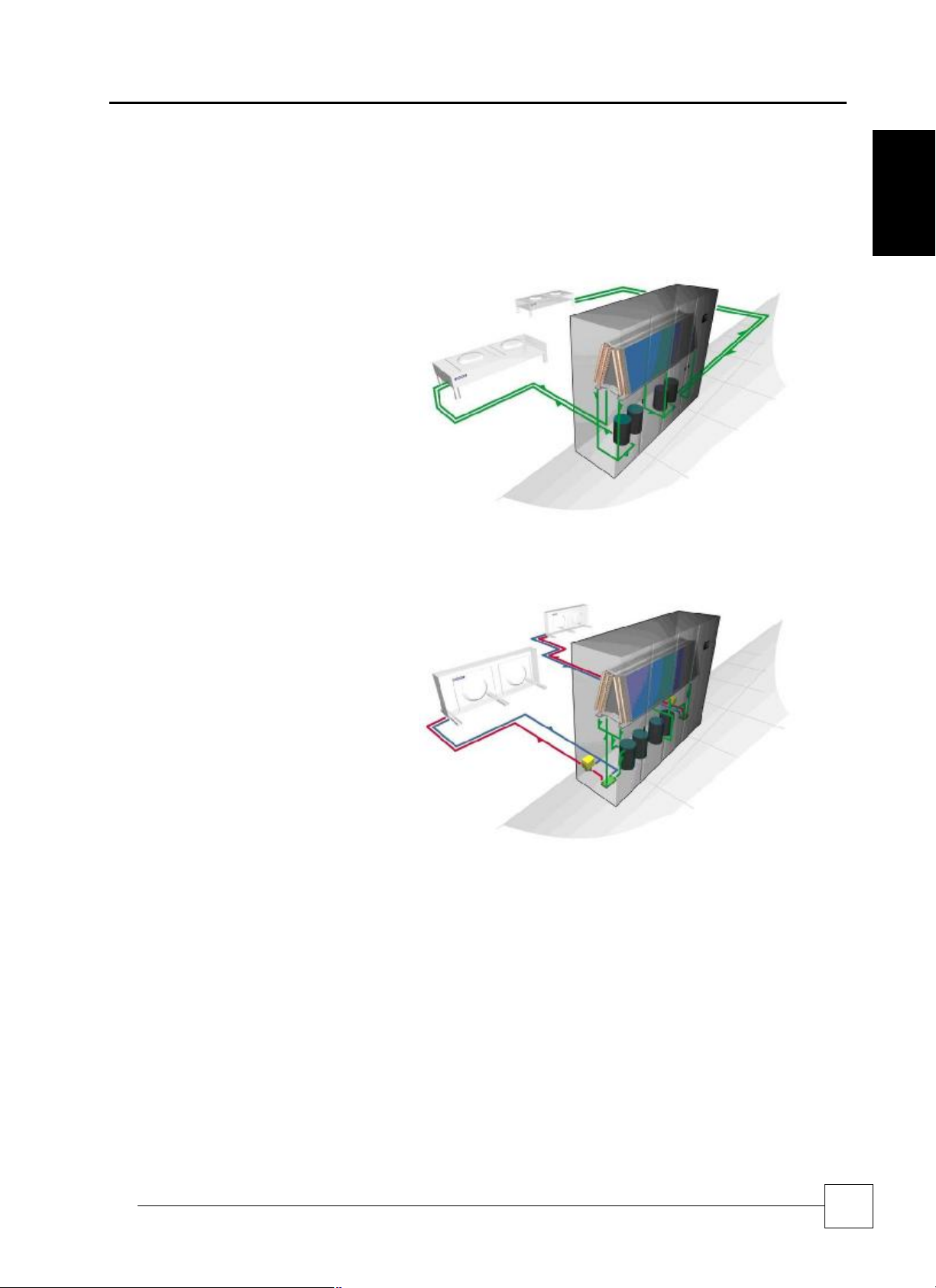
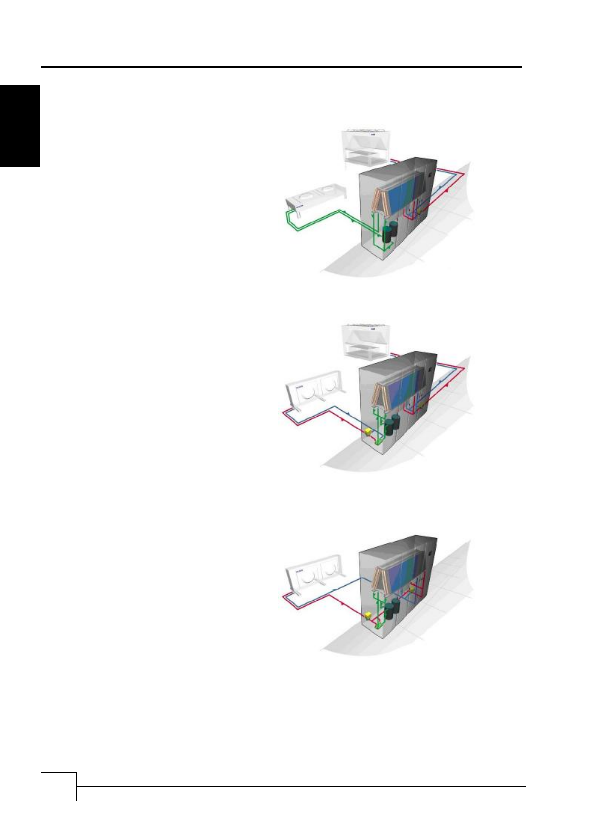
System Configurations
Dual Circuit
X2X2
The SmartCool X2X2 is an air cooled, direct
expansion (DX), double circuit system linked
to two separate, remotely mounted air cooled
condensers.
Optimised for heat transfer using energy
efficient refrigerant R410A in each circuit, the
X2X2 system is located within the conditioned
space, absorbing room heat and transferring it
outside to the condensers.
By using one or more same/dissimilar sized
scroll compressors across the X2X2 double
circuit, part load efficiency can be maximised
and capacity more precisely matched to
application.
SmartCoolTM – D
General
W2W2
Suitable for applications favouring reduced
refrigerant charges, the SmartCool W2W2 is a
double circuit system featuring, DX cooling
within the case and dry coolers outside.
Warm room air is passed through two
completely independent evaporator coils and
an integral plate condenser transfers the heat
load to the glycol solution which is then
channelled outside to two air cooled dry
coolers.
9
Precision Air Conditioning
SmartCoolTM - D
Dual Cool
General
X2C0
For redundancy in critical applications, the SmartCool
dual cool X2C0 offers two different cooling mediums,
air cooled DX and chilled water, within the same case.
The X2C0 system is managed by the Airetronix
microprocessor to select which medium acts as the
primary source of cooling or which acts as back-up,
should the primary source fail or is unable to cope with
the heat load.
Precision Air Conditioning
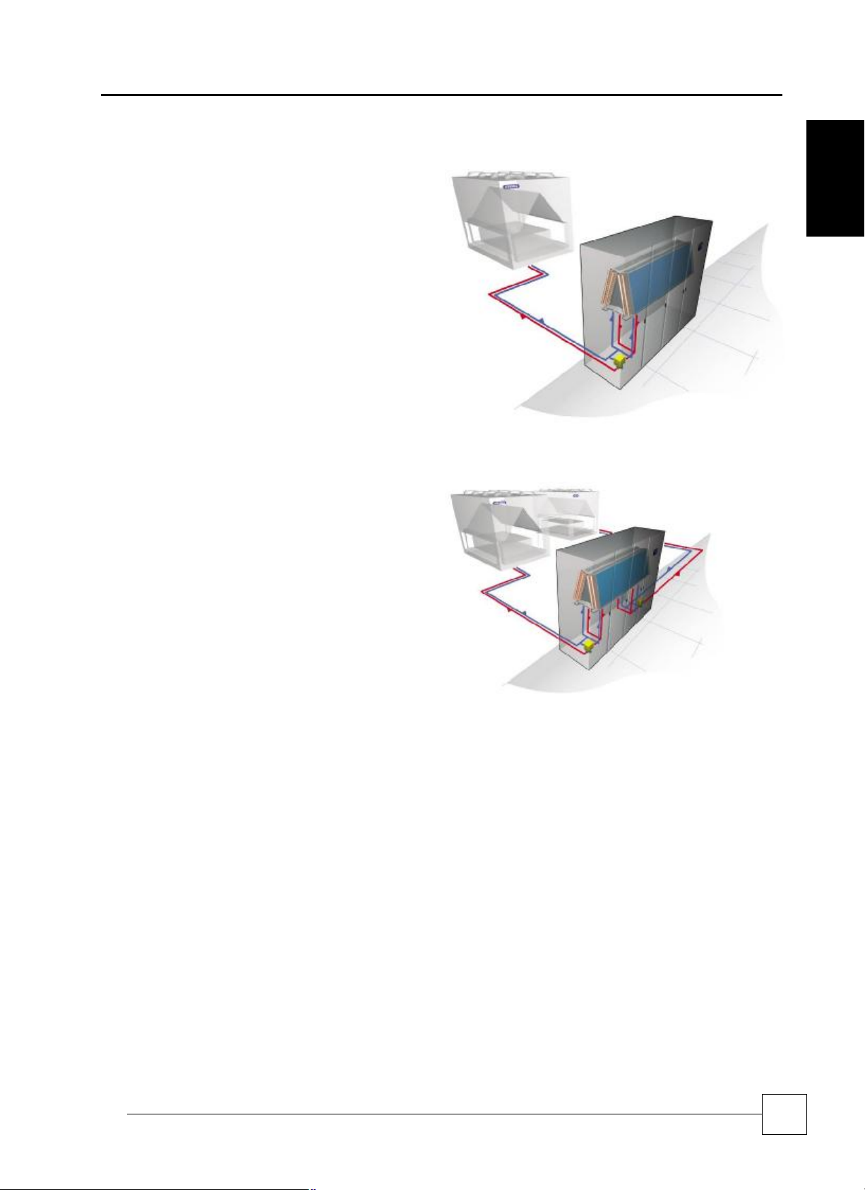
W2C0
For applications where a water cooled system is
preferred over air cooled, the SmartCool W2C0
comprises two different cooling mediums within the
same case: DX water cooled, as in the W2W2 system,
and chilled water, as in the C000 system.
The Airetronix microprocessor elects which medium
acts as the primary source of cooling and which as
back-up, if the primary source fails or is unable to cope
with the heat load.
W2F0
The W2F0 system includes a free-cooling coil in
conjunction with the evaporator. In low ambient
conditions, particularly in relation to the high
temperatures and continuous system operation of a
server environment, the W2F0 system will run with
minimum energy. At times of higher ambient,
sophisticated Airetronix controls technology will
modulate the 3-way water regulating valves to
transition from free cooling back to mechanical cooling.
Typically the SmartCool W2F0 single circuit freecooling system uses 46%* less energy than a standard
air cooled DX system.
10
Installation, Maintenance and Commissioning Manual :6877419 02/2013
Precision Air Conditioning
Installation, Maintenance and Commissioning Manual :6877419 02/2013
Chilled Water
Precision Air Conditioning
C000
Where a chilled water single circuit system is preferred,
warm room air is blown across the efficient cooling coils
of the SmartCool C000 and the heat transferred to a
chilled water system such as Airedale’s high efficiency
TurboChill.
By controlling the 3-way water regulating valve, the
intelligent Airetronix microprocessor can achieve precise
control of temperature and humidity.
SmartCoolTM – D
General
C0C0
In the SmartCool C0C0 unit, the cooling coils are split
into two independent systems, each with a 3-way water
regulating valve, and cooled by chilled water from two
separate chillers.
For extra security, the dual circuit configuration of
SmartCool C0C0 offers 2N redundancy.
11
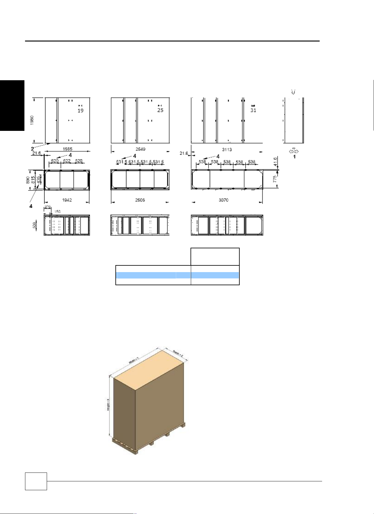
Precision Air Conditioning
Dimensions
Stan
dard Airflow Configuration (mm)
Packed Dimensions
SmartCoolTM - D
Installation Data
Installation
Precision Air Conditioning
SC19D
SC25D
SC31D
(1)
(2)
(3)
(4)
Forward or reversed air discharge available as standard on all products. Does not require configuring.
Area denotes services entry location. For specific details please contact Airedale.
Open base. Shaded area denotes air discharge.
M6 fixing holes positions for mounting ceiling duct extensions or plenums.
For specific markets units shall be shipped, mounted on wooden pallet and covered with
polythene. The pallet shall be mechanically fixed to the unit for transportation only
(Please contact Airedale for this option)
mm 1980 x 890 x 1985
mm 1980 x 890 x 2549
mm 1980 x 890 x 3113
H x D x W
X = 160mm
Y = 50mm
Z = 50mm
12
Installation, Maintenance and Commissioning Manual :6877419 02/2013

Precision Air Conditioning
Installation, Maintenance and Commissioning Manual :6877419 02/2013
Po
sitioning
Minimum
U
nit Clearance
Open & Enclosed Floorstand Option
SC19D
SC25D
Minim
um Ceiling Clearance
- (D)
SC19D
SC25D
SC31D
Precision Air Conditioning
SmartCoolTM – D
(D)
Installation
(2)
(1)
SC31D
mm 1985 800
mm 2549 800
mm 3113 800
A B C - Floorstand(3)
Min 200 – Max 750
(+ 50mm Feet Adjustable +/-
20mm) (4)
Forward Only Forward and 1 Side Forward and 2 Sides All Faces
mm
mm
mm
720 500 380 250
740 550 440 280
750 590 480 300
Notes
(1) Shown with optional open floor stand.
(2) Shaded area indicates minimum service and maintenance requirements. The unit must be installed with allowance for carpet tile clearance.
(3) Dimension C denotes recommended minimum/maximum floor stand height, refer to Airedale for special applications, please specify at order.
(4) Min = Threaded foot at minimum extension (additional to “C” dimension).
Max = Threaded foot at maximum extension (additional to “C” dimension).
13

Precision Air Conditioning
SmartCoolTM - D
Precision Air Conditioning
Electrical Services Incoming Cable
Service connections to the smartcool unit are from the left hand side. Provision must be made when sizing cable lengths.
Installation
Mains Electrical Incoming Isolator Termination
Electrical Services Entry Option 2
The Floorstand provided by Airedale however has provision for cable entry via the right hand side should it be required,
adjacent to the condensate drain.
Mechanical Services Entry + Electrical Option 1
Option 1
Option 2
Electrical services through floor stand
(Next to condensate drain)
Incoming Mains Gland Plate
1
2
4 hole centres are punched in the gland plate for
location of cable glands. The plate is removable for
drilling to required size.
3
4
Holes1 and 2 for interconnecting wiring to Outdoor unit.
Holes 3 and 4 for Mains incoming Supply A and B
14
Installation, Maintenance and Commissioning Manual :6877419 02/2013

Precision Air Conditioning
Installation, Maintenance and Commissioning Manual :6877419 02/2013
Precision Air Conditioning
Weights
SmartCoolTM – D
Unit Shipped Weight (kg) Installed Weight (kg)
SC19D055-X2X2-0 900 900
SC19D070-X2X2-0 900 910
SC19D080-X2X2-0 900 910
X2X2
X2C0
Note
(1) Shipped weights
(2) Installed weight includes refrigerant charges/ internal water volume.
SC25D080-X2X2-0 1020 1020
SC25D090-X2X2-0 1110 1120
SC25D100-X2X2-0 1130 1130
SC31D100-X2X2-0 1280 1290
SC31D120-X2X2-0 1300 1310
SC31D130-X2X2-0 1300 1310
Unit Shipped Weight (kg) Installed Weight (kg)
SC19D033-X2C0-0 820 860
SC19D038-X2C0-0 820 860
SC19D045-X2C0-0 820 860
SC19D064-X2C0-0 890 920
SC19D070-X2C0-0 900 930
SC19D076-X2C0-0 900 930
SC25D045-X2C0-0 940 980
SC25D050-X2C0-0 990 1030
SC25D055-X2C0-0 1000 1040
SC25D067-X2C0-0 1010 1050
SC25D073-X2C0-0 1010 1060
SC25D080-X2C0-0 1020 1060
SC31D055-X2C0-0 1150 1200
SC31D065-X2C0-0 1150 1210
SC31D075-X2C0-0 1160 1210
SC31D077-X2C0-0 1170 1220
SC31D080-X2C0-0 1170 1220
SC31D083-X2C0-0 1170 1220
Installation
15

Precision Air Conditioning
SmartCoolTM - D
Weights
Unit Shipped Weight (kg) Installed Weight (kg)
SC19D055-W2W2-0 940 940
SC19D070-W2W2-0 970 980
SC19D080-W2W2-0 970 980
Installation
W2W2
W2C0
Note
(1) Shipped weights
(2) Installed weight includes refrigerant charges/ internal water volume.
SC25D080-W2W2-0 1090 1110
SC25D090-W2W2-0 1220 1230
SC25D100-W2W2-0 1230 1250
SC31D100-W2W2-0 1390 1400
SC31D120-W2W2-0 1400 1410
SC31D130-W2W2-0 1400 1420
Unit Shipped Weight (kg) Installed Weight (kg)
SC19D033-W2C0-0 850 880
SC19D038-W2C0-0 860 890
SC19D045-W2C0-0 860 890
SC19D064-W2C0-0 950 980
SC19D070-W2C0-0 950 980
SC19D076-W2C0-0 960 990
SC25D045-W2C0-0 980 1020
SC25D050-W2C0-0 1050 1090
SC25D055-W2C0-0 1050 1100
SC25D067-W2C0-0 1070 1110
SC25D073-W2C0-0 1070 1120
SC25D080-W2C0-0 1080 1120
SC31D055-W2C0-0 1210 1260
SC31D065-W2C0-0 1220 1270
SC31D075-W2C0-0 1220 1270
SC31D077-W2C0-0 1230 1280
SC31D080-W2C0-0 1230 1280
SC31D083-W2C0-0 1230 1290
Precision Air Conditioning
16
Installation, Maintenance and Commissioning Manual :6877419 02/2013

Precision Air Conditioning
Installation, Maintenance and Commissioning Manual :6877419 02/2013
Precision Air Conditioning
Weights
Unit Shipped Weight (kg) Installed Weight (kg)
SmartCoolTM – D
SC19D033-W2F0-0 850 880
SC19D038-W2F0-0 860 890
SC19D045-W2F0-0 860 890
SC19D064-W2F0-0 950 980
SC19D070-W2F0-0 950 980
SC19D076-W2F0-0 960 990
SC25D045-W2F0-0 980 1020
SC25D050-W2F0-0 1050 1090
W2F0
C000
SC25D055-W2F0-0 1050 1100
SC25D067-W2F0-0 1070 1110
SC25D073-W2F0-0 1070 1120
SC25D080-W2F0-0 1080 1120
SC31D055-W2F0-0 1210 1260
SC31D065-W2F0-0 1220 1270
SC31D075-W2F0-0 1220 1270
SC31D077-W2F0-0 1230 1280
SC31D080-W2F0-0 1230 1280
SC31D083-W2F0-0 1230 1290
Unit Shipped Weight (kg) Installed Weight (kg)
SC19D065-C000-0 725 780
SC19D075-C000-0 725 780
SC19D090-C000-0 730 780
SC25D090-C000-0 840 920
SC25D100-C000-0 840 920
SC25D110-C000-0 840 920
SC31D110-C000-0 1000 1080
SC31D130-C000-0 1000 1080
SC31D150-C000-0 1000 1080
Installation
Unit Shipped Weight (kg) Installed Weight (kg)
SC19D033-C0C0-0 730 790
SC19D038-C0C0-0 730 790
SC19D045-C0C0-0 730 790
C0C0
Note
(1) Shipped weights
(2) Installed weight includes refrigerant charges/ internal water volumes.
SC25D045-C0C0-0 850 930
SC25D050-C0C0-0 850 930
SC25D055-C0C0-0 850 930
SC31D055-C0C0-0 1010 1100
SC31D065-C0C0-0 1010 1100
SC31D075-C0C0-0 1010 1100
17
Precision Air Conditioning
IMPORTANT
Tandem Compressor and suction throttle valve applications:
REMEM
BER excessive pressure loss in interconnecting pipework will impair system
Oil Traps
Pipe Supports
CAUTION
All pipework should be clamped prior to insulation being applied. Clamping over
Horizontal Sections
SmartCoolTM - D
Precision Air Conditioning
Refrigerant Pipe Sizing Guide
The refrigerant pipe sizing information below is for a guide only. Pipe sizes based on 100% load.
Liquid Disch
SC19D055-X2X2-0 CR50 1/2" 7/8" 5/8" 7/8" 3/4" 5/8" 7/8" 7/8"
SC19D070-X2X2-0 CR65 5/8" 7/8" 5/8" 7/8" 7/8" 5/8" 7/8" 7/8"
SC19D080-X2X2-0 CR65 5/8" 7/8" 5/8" 7/8" 7/8" 3/4" 7/8" 7/8"
SC25D080-X2X2-0 CR65 5/8" 7/8" 5/8" 7/8" 7/8" 3/4" 7/8" 7/8"
Installation
SC25D090-X2X2-0 CR65 7/8" 1 1/8" 5/8" 7/8" 7/8" 3/4" 7/8" 7/8"
SC25D100-X2X2-0 CR80 7/8" 1 1/8" 3/4" 1 1/8" 1 1/8" 3/4" 1 1/8" 1 1/8"
SC31D100-X2X2-0 CR80 7/8" 1 1/8" 3/4" 1 1/8" 1 1/8" 3/4" 1 1/8" 1 1/8"
SC31D120-X2X2-0 CR105 7/8" 1 1/8" 3/4" 1 1/8" 1 1/8" 3/4" 1 1/8" 1 1/8"
SC31D130-X2X2-0 CR105 7/8" 1 1/8" 3/4" 1 1/8" 1 1/8" 7/8" 1 1/8" 1 1/8"
SC19D033-X2C0-0 CR50 1/2" 7/8" 5/8" 7/8" 3/4" 5/8" 7/8" 7/8"
SC19D038-X2C0-0 CR65 5/8" 7/8" 5/8" 7/8" 7/8" 5/8" 7/8" 7/8"
SC19D045-X2C0-0 CR65 5/8" 7/8" 5/8" 7/8" 7/8" 3/4" 7/8" 7/8"
SC19D064-X2C0-0 CR105 5/8" 7/8" 3/4” 1 1/8” 1 1/8” 7/8” 1 3/8” 1 1/8”
SC19D070-X2C0-0 CR105 7/8" 1 1/8" 3/4” 1 1/8” 1 1/8” 7/8” 1 3/8” 1 1/8”
SC19D076-X2C0-0 CR105 7/8" 1 1/8" 3/4” 1 1/8” 1 1/8” 7/8” 1 3/8” 1 1/8”
SC25D045-X2C0-0 CR65 7/8" 1 1/8" 5/8" 7/8" 7/8" 3/4" 7/8" 7/8"
SC25D050-X2C0-0 CR65 7/8" 1 1/8" 5/8" 7/8" 7/8" 3/4" 7/8" 7/8"
SC25D055-X2C0-0 CR80 7/8" 1 1/8" 3/4" 1 1/8" 1 1/8" 3/4" 1 1/8" 1 1/8"
SC25D067-X2C0-0 CR105 7/8" 1 3/8" 3/4” 1 1/8” 1 1/8” 7/8” 1 3/8” 1 1/8”
SC25D073-X2C0-0 CR105 7/8" 1 3/8" 3/4” 1 1/8” 1 1/8” 7/8” 1 3/8” 1 1/8”
SC25D080-X2C0-0 CR105 7/8" 1 3/8" 3/4” 1 1/8” 1 1/8” 7/8” 1 3/8” 1 1/8”
SC31D055-X2C0-0 CR80 7/8" 1 3/8" 3/4" 1 1/8" 1 1/8" 3/4" 1 1/8" 1 1/8"
SC31D065-X2C0-0 CR105 7/8" 1 3/8" 3/4" 1 1/8" 1 1/8" 3/4" 1 1/8" 1 1/8"
SC31D075-X2C0-0 CR105 7/8" 1 3/8" 3/4" 1 1/8" 1 1/8" 7/8" 1 1/8" 1 1/8"
SC31D077-X2C0-0 CR105 7/8" 1 3/8" 3/4” 1 1/8” 1 1/8” 7/8” 1 3/8” 1 1/8”
SC31D080-X2C0-0 CR105 7/8" 1 3/8" 3/4” 1 1/8” 1 1/8” 7/8” 1 3/8” 1 1/8”
SC31D083-X2C0-0 CR105 7/8" 1 3/8" 3/4” 1 1/8” 1 1/8” 7/8” 1 3/8” 1 1/8”
(1) For interconnecting pipework with a predominantly horizontal layout.
(2) For interconnecting pipework with a predominantly vertical layout.
(3) Careful pipework selection must be done if the liquid line rises. Additional system sub cooling may be required to overcome friction losses.
Equivalent Pipe Lengths with R410A
Indoor
Unit
Outdoor
Unit
Indoor Unit
Connection Size 0-15m Discharge 15-40m Discharge
Liquid
(3)
Horizontal
(1)
Vertical
(2)
Liquid
(3)
Horizontal
(1)
Vertical
(2)
In part load, gas velocity should be taken into account when selecting and commissioning
pipework to ensure full oil return.
performance; this should be factored in during the design of the system and where
necessary oil separators employed.
Excessive pressure drop in liquid lines can cause poor refrigerant distribution to
expansion devices and can cause malfunction of the system (especially with condensers
lower than the evaporator)
For long vertical rises in both liquid and discharge lines, it is essential that oil traps are
located every 4m to ensure proper oil movement / entrapment. In addition there should be
an oil trap at the exit of the air handling unit before a vertical riser is applied (refer to
example below).
The following table identifies the maximum
distance between pipe supports on vertical
and horizontal pipe runs.
insulation is not acceptable.
Pipe O/D (inches) Support distance (m)
3/8 - 7/8 1.0
1 1/8 - 2 1/8 2.0
It is good practice to ensure a slight gradient toward the compressor in the direction of the
refrigerant flow for suction lines running horizontal. This assists oil return to the
compressor. A gradient of approximately 1:200 (0.5%) shall be used.
18
Installation, Maintenance and Commissioning Manual :6877419 02/2013

Precision Air Conditioning
Installation, Maintenance and Commissioning Manual :6877419 02/2013
Liquid Line
Pipe Insulation
Condenser above Air Handling Unit
Condenser below Air Handling Unit
4m
Refrigerant
C
harging Guide
Unit Refrigerant
Charge
(1)
excessive.
Precision Air Conditioning
If the system is configured with the SmartCool higher than the condenser unit h it may
be required to increase the degree of sub cooling to prevent flashing gas. This flashing is
caused by excess pressure drop caused by the static head of refrigerant and can cause
poor operation of the evaporator and metering device.
Careful pipe sizing is recommended to ensure that the liquid does not form gas due to
excess pressure drop
Increasing the liquid line size minimizes pipe friction and flashing due to friction pressure
drop.
However as a fail safe it is recommended that the condenser is installed below the
indoor unit to allow for correct liquid drain.
The liquid line of the system must be insulated if passing through extremely warm places
(Boiler houses etc). Ensuring that the refrigerant does not become flash gas.
t
SmartCoolTM – D
Installation
Discharge Line
The following information can be used to estimate the refrigerant quantity required in a
typical split system installation.
The following table shows the refrigerant charge / circuit for the indoor and outdoor units.
(kg/Circuit)
(Indoor Unit) kg/Circuit
SC19D055-X2X2
SC19D070-X2X2
SC19D080-X2X2
SC25D080-X2X2
SC25D090-X2X2
SC25D100-X2X2
SC31D100-X2X2
SC31D120-X2X2
SC31D130-X2X2
SC19D033-X2C0
SC19D038-X2C0
SC19D045-X2C0
SC19D064-X2C0
SC19D070-X2C0
SC19D076-X2C0
SC25D045-X2C0
SC25D050-X2C0
SC25D055-X2C0
SC25D067-X2C0
SC25D073-X2C0
SC25D080-X2C0
SC31D055-X2C0
SC31D065-X2C0
SC31D075-X2C0
SC31D077-X2C0
SC31D080-X2C0
SC31D083-X2C0
(1)Fitted with optional hot gas re-heat
t
Warning: May have flash gas occurring
in liquid line if riser friction losses are
Liquid Diagrams above for illustration only
Indoor Unit Standard Condenser Larger Condenser
4.41 4.56
4.66 4.81
4.66 4.81
5.84 6.04
6.37 6.60
6.38 6.60
7.56 7.83
7.57 7.83
7.67 7.94
4.34 4.49
4.59 4.74
4.59 4.74
5.13 5.33
5.13 5.34
5.14 5.34
5.77 5.97
6.31 6.53
6.31 6.53
6.31 6.56
6.32 6.57
6.32 6.57
7.49 7.75
7.49 7.76
7.49 7.76
7.50 7.79
7.50 7.79
7.50 7.79
HGRH
kg/Circuit (Outdoor Unit) kg/Circuit (Outdoor Unit) kg/Circuit
CR50
CR65
CR65
CR65
CR65
CR80
CR80
CR105
CR105
CR50
CR65
CR65
CR105
CR105
CR105
CR65
CR65
CR80
CR105
CR105
CR105
CR80
CR105
CR105
CR105
CR105
CR105
4.9
9.78
9.78
9.78
9.78
8.37
8.37
16.72
16.72
4.9
9.78
9.78
16.72
16.72
16.72
9.78
8.37
8.37
16.72
16.72
16.72
8.37
16.72
16.72
16.72
16.72
16.72
CR65
CR80
CR80
CR80
CR80
CR105
CR105
CR130
CR130
CR65
CR80
CR80
CR130
CR130
CR130
CR80
CR80
CR105
CR130
CR130
CR130
CR105
CR130
CR130
CR130
CR130
CR130
9.78
8.37
8.37
8.37
8.37
16.72
16.72
22.05
22.05
9.78
8.37
8.37
22.05
22.05
22.05
8.37
8.37
16.72
22.05
22.05
22.05
16.72
22.05
22.05
22.05
22.05
22.05
19

Precision Air Conditioning
Liquid
Line Refrigerant
IMPORTANT
The pipe
sizes/refrigerant charges quoted are for guidance only. It is the responsibility of
Split systems may require additional oil which should be added to the low side of
Design should be in accordance with accepted refrigeration prac
tice to ensure good oil
Calculation of
Liquid Line
Calculation of
System
Example
Selecting The Liquid Line Size
Liquid Line Refrigerant
System Refrigerant Charge
SmartCoolTM - D
Charge (kg/m)
Installation
Refrigerant Charge (kg)
Refrigerant Charge (kg)
Precision Air Conditioning
The following table shows the refrigerant charge / metre for the liquid line, using R410A
and assuming a liquid line temperature of 40°C.
Liquid Line (m) kg/m
3/8” 0.05
1/2” 0.09
5/8” 0.15
3/4” 0.21
7/8” 0.30
1 1/8” 0.53
the installing contractor/site engineer to check the pipe sizes/refrigerant charges are correct
for each system installation and application. Excess pressure drop on a system may require
additional refrigerant charges to ensure correct unit operation.
each compressor.
return to the compressor(s) under all normal operating conditions.
The liquid line refrigerant charge can be calculated using the following equation:
LR = L x m
The system refrigerant charge can be calculated using the following equation:
SR = LR + IR + OR
Where:
LR = Total Liquid Line Refrigerant charge (kg)
L = Length of Interconnecting pipework (metres)
m = Liquid Line Refrigerant charge / metre. Refer to
Liquid Line Refrigerant
Charge (kg/m), above.
Where:
SR = Total System Refrigerant charge (kg)
LR = Total Liquid Line Refrigerant charge. (As calculated from above)
IR = Indoor Unit Refrigerant Charge.
OR = Outdoor Unit Refrigerant Charge.
Indoor Unit Model Ref. = SC19D055-X2X2-0
Outdoor Unit Model Ref. = CR50 Condenser
Interconnecting Pipework = 10 metres
From the Refrigerant Pipe Sizing Guide, the liquid line size given for pipework length of 10 metres
is:
Liquid Line Size = 5/8”
LR = L x m
Charge
LR = 10 x 0.15
SR = LR + IR + OR
SR = 1.5 + 5.57 + 4.9 System Refrigerant Charge = 10.81kg / Circuit
Where:
L = 10 metres
m = 0.15 kg/m
Liquid Line Charge = 1.5 kg
Where:
LR = 1.5 kg. (As calculated from above)
IR = 4.41 kg
OR = 4.9 kg
20
Installation, Maintenance and Commissioning Manual :6877419 02/2013

Precision Air Conditioning
Installation, Maintenance and Commissioning Manual :6877419 02/2013
Liquid Sub Cooling
Precision Air Conditioning
The degree of liquid sub cooling required to prevent flashing of liquid refrigerant can be calculated by
the following method.
Given the following as an example:
· Refrigerant R410A
· Condensing temperature (54.4°C)
· Liquid lift 20m
· Piping friction loss 0.21 bar
· Losses through valves and fittings 0.5 Bar
1. Determine the pressure drop due to pipe friction = 0.21 Bar
2. Pressure drop due to valves and fittings = 0.5 Bar
3. Pressure loss due to liquid lift = height x 0.115 = 20 x 0.115 = 2.3 bar
Note:- At normal liquid temperatures the static pressure loss due to elevation at the top of a liquid lift
0.115 bar/m
Therefore:- Total pressure loss in liquid line = 3.01bar
Condensing pressure @ Condensing temperature (54.4°C) = 34 Bar
Total pressure loss in liquid line = 3.01 Bar
Nett pressure at Expansion valve = 34 - 3.01 = 30.99 bar
Saturation temperature at the Nett pressure at expansion valve (30.99 bar) = 52°C
(from Refrigerant tables)
SmartCoolTM – D
Installation
Sub cooling required
= Condensing temperature — Saturation temperature at the Nett pressure at expansion valve
= 54.4 - 52 = 2.4 °C
Therefore liquid sub cooling required to prevent liquid flashing = 2.4 °C
Packaged Unit Pre-Charged Refrigerant Volumes
Indoor unit kg / circuit HGRH kg / circuit Indoor unit kg / circuit HGRH kg / circuit
SC19D055-W2W2 5.75 5.90 SC19D033-W2F0 5.68 5.83
SC19D070-W2W2 7.32 7.47 SC19D038-W2F0 7.25 7.40
SC19D080-W2W2 7.32 7.47 SC19D045-W2F0 7.25 7.40
SC25D080-W2W2 8.51 8.70 SC19D064-W2F0 9.60 9.81
SC25D090-W2W2 10.85 11.07 SC19D070-W2F0 9.61 9.81
SC25D100-W2W2 10.85 11.07 SC19D076-W2F0 9.61 9.82
SC31D100-W2W2 12.04 12.30 SC25D045-W2F0 8.44 8.63
SC31D120-W2W2 12.04 12.30 SC25D050-W2F0 10.78 11.00
SC31D130-W2W2 12.04 12.31 SC25D055-W2F0 10.78 11.00
SC19D033-W2C0 5.68 5.83 SC25D067-W2F0 10.79 11.04
SC19D038-W2C0 7.25 7.40 SC25D073-W2F0 10.79 11.04
SC19D045-W2C0 7.25 7.40 SC25D080-W2F0 10.80 11.04
SC19D064-W2C0 9.60 9.81 SC31D055-W2F0 11.96 12.23
SC19D070-W2C0 9.61 9.81 SC31D065-W2F0 11.97 12.23
SC19D076-W2C0 9.61 9.82 SC31D075-W2F0 11.97 12.23
SC25D045-W2C0 8.44 8.63 SC31D077-W2F0 11.97 12.26
SC25D050-W2C0 10.78 11.00 SC31D080-W2F0 11.98 12.27
SC25D055-W2C0 10.78 11.00 SC31D083-W2F0 11.98 12.27
SC25D067-W2C0 10.79 11.04
SC25D073-W2C0 10.79 11.04
SC25D080-W2C0 10.80 11.04
SC31D055-W2C0 11.96 12.23
SC31D065-W2C0 11.97 12.23
SC31D075-W2C0 11.97 12.23
SC31D077-W2C0 11.97 12.26
SC31D080-W2C0 11.98 12.27
SC31D083-W2C0 11.98 12.27
(1)Fitted with optional hot gas re-heat
21

Precision Air Conditioning
Dry
Cooler (kW)
Calculation of
Design
V
r
D
r
Ca
lculation of
Indoor Unit
D
D
This will typically occur when the water/glycol temperature is approximately 20°C and the
The indoor unit pressure drop will reduce at other operating conditions.
Specific Heat Capacity (Cp)
Pressure Drop Correction
SmartCoolTM - D
Design Data – Water Cooled & Free Cooling
Installation
Volumetric Flow Rate (l/s)
Pressure Drop (DPs)
The dry cooler design duty is equivalent to the Total Heat of Rejection (THR) from the indoor unit.
This value can be taken from the performance data in the technical manual using the following.
Parameters required are:
· Ambient conditions (°C dB) Airedale recommend a 10°C lower than the EWT.
· Glycol content (%)
· Entering & leaving water/glycol temperatures (°C) (EWT and LWT)
· Mean condensing temperature (°C) Based on 5°C above leaving water/glycol temperature
The maximum design volumetric flow rate can be calculated using the following equation:
&
=
x Cp
Where:
Q = Total Heat Rejection (kW).
T = Temperature Difference between Water/Glycol Entering/ Leaving (°C).
= Density. Refer to table below.
Cp = Specific heat capacity. Refer to table below.
The maximum indoor unit pressure drop can be calculated using the following equation:
DPs= DPw x Pc
Using the volumetric flow rate calculated above, the pressure drop (DPw) can be taken from the
relevant pressure drop graph..
Where:
Ps = Maximum Water/Glycol Pressure Drop for the indoor unit (kPa).
Pw = Equivalent Water Pressure Drop for indoor unit (kPa).
Pc = % Glycol Pressure Drop Correction Factor @ 20°C Water Temperature.
The resultant pressure drop (DPs) is the maximum pressure drop based on the indoor unit
running at the prescribed conditions.
Precision Air Conditioning
Q
x ΔT
Refer to table below.
Density (r)
Factor (Pc)
water/glycol is being circulated through the free cooling coil and through the water cooled
condenser.
Water/Glycol Temperature °C
20 4.183 3.972 3.815 3.645 3.468
25 4.181 3.981 3.826 3.660 3.485
30 4.179 3.989 3.838 3.674 3.502
35 4.178 3.998 3.849 3.688 3.518
40 4.179 4.007 3.861 3.702 3.535
45 4.181 4.015 3.872 3.716 3.552
Water/Glycol Temperature °C
20 998 1013 1030 1045 1060
25 997 1012 1028 1043 1058
30 996 1010 1026 1041 1055
35 994 1008 1024 1039 1053
40 992 1006 1022 1036 1050
45 990 1003 1020 1035 1048
Water/Glycol Temperature °C
20 0.983 1.0125 1.054 1.0958 1.15
0% / 0°C 10% / -4°C 20% / -9°C 30% / -15°C 40% / -23°C
Fc Fc Fc Fc Fc
0% / 0°C 10% / -4°C 20% / -9°C 30% / -15°C 40% / -23°C
Fc Fc Fc Fc Fc
0% 10% 20% 30% 40%
Pc Pc Pc Pc Pc
Ethylene Glycol (Volume) / Freezing Point °C
Ethylene Glycol (Volume) / Freezing Point °C
Ethylene Glycol (Volume)
22
Installation, Maintenance and Commissioning Manual :6877419 02/2013

Precision Air Conditioning
Installation, Maintenance and Commissioning Manual :6877419 02/2013
System Pressure
IMPORTANT
Low pressure transducers and switches must be removed whilst the high pressure
CAUTION
Before carrying out the pressure test, precautions shall be taken to evacuate
all
System Leak Test
RECORD
Record on commissioning sheet provided once completed.
IMP
ORTANT
Filter Drier
IMPORTANT
Failure to correctly fit a filter drier can cause malfunction of the system.
They are
Precision Air Conditioning
Installation Data
The system must be pressure tested to ensure that the pipework is installed satisfactory.
Strength Test
Nitrogen (Oxygen free) should only be used.
Strength Pressure Test is the pressure applied to a refrigeration system for its integral
strength and it is usually defined as maximum working pressure (MWP) x factor of 1.43.
The pressure test ideally should be carried out for a period of one hour.
strength test is carried out.
personnel from the area of risk and post notices advising that the system or
equipment is under pressure.
The test pressure in the system should be held for at least one hour. A longer period may
be appropriate for larger systems or a fall in pressure due to leaks may not be detected.
Any fall in pressure indicates a leak which should be traced.
SmartCoolTM – D
Installation
The system leak test is carried out with the low pressure transducers and switches fitted.
Leak Pressure Test is the pressure applied to a refrigeration system or part of a system to
test for leakage. This test pressure is defined as Maximum Working Pressure of the
particular system x factor of 1.1.
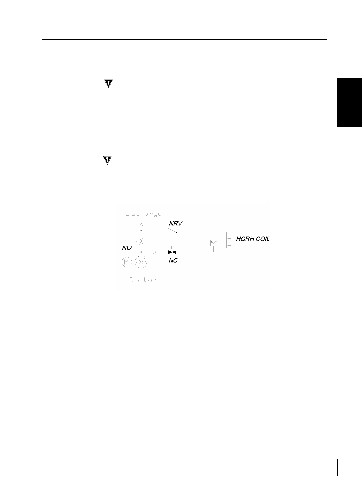
It is important that solenoid valves are energised correctly to ensure that the Hot Gas
Reheat coil is fully pressure tested (the normally closed (NC) valve should be energised).
The use of a magnetic coil lifter is recommended.
The filter drier must be installed as close to the expansion valve as possible. It should be
the last component within the system to be installed.
however no substitute to good refrigeration practices with regard to system
cleanliness.
23

Precision Air Conditioning
Evacuation
RECORD
Record on commissioning sheet provided once completed.
IMPORTANT
CAUTION
Ensure that the
e
vacuation gauge is isolated before introduc
ing any pressure. The
SmartCoolTM - D
Installation Data
Installation
Precision Air Conditioning
Evacuation for systems operating on R410A refrigerant should be carried out as follows
1 The procedure should be carried out using a high vacuum pump. The pump should
be connected to the high and low pressure sides of the system via a gauge manifold
fitted with compound gauges. A high vacuum gauge should be fitted to the system at
the furthest point from the vacuum pump.
2 Triple evacuation should be used to ensure that all contaminants are removed or at
least reduced to significantly low proportions.
3 The vacuum pump should be operated until a pressure of 1.5 Torr (200 Pa) absolute
pressure is reached, at which time the vacuum pump should be stopped and the
vacuum broken with oxygen free nitrogen until the pressure rises above zero.
4 The above operation should be repeated a second time.
5 The system should then be evacuated a third time but this time to 0.5 Torr (absolute
pressure and broken with the correct refrigerant, until pressures equalise between
the charging bottle and the system.
It is important that solenoid valves are energises correctly to ensure that the Hot Gas
Reheat Coil is fully evacuated. (The Normally Closed (NC) valve should be energised).
The use of a magnetic coil lifter is recommended.
24
gauge may become dangerous when exposed to any positive pressure.
Installation, Maintenance and Commissioning Manual :6877419 02/2013
Precision Air Conditioning
Installation, Maintenance and Commissioning Manual :6877419 02/2013
Refrigerant Handling
CAUTION
P
ersonal
p
rotective equipment must be worn
when handling refrigerants.
Charging Gauges
Refrigerant Quality
Refrigerant Charge
RECORD
Record on commissioning sheet provided once completed.
IMPORTANT
Schrader Caps
Final Leak Test
Precision Air Conditioning
Installation Data
Only certified personnel must charge the systems with refrigerant
The refrigerant Schrader connections on the SmartCool units are 5/16” to allow for the
increase working pressures of R410A. Gauges designed for R410A must only be used.
The system must be charged with clean virgin refrigerant R410A only.
The exact refrigerant charge is dependant on site circumstances and operating
Weights
temperatures. Pipework runs must be taken into consideration. The refrigerant charge
must be weighed into the system and recorded within your F-Gas record.
It is important that solenoid valves are energised correctly to ensure that the Hot Gas
ReHeat coil is broken of vacuum (the Normally Closed (NC) valve should be energised).
The use of a magnetic coil lifter is recommended.
SmartCoolTM – D
Installation
The valve must also be energised when charging the system with refrigerant.
The solenoid valve head must be put back on the body before unit operation.
Schrader caps must be replaced following connection of service gauges to the unit.
A final leak test must be carried out following removal of service gauges prior to leaving
site ensuring that the system complies with F-Gas regulations.
25
Precision Air Conditioning
Oil Charging Guide
Compressors
The compressor oil sight glass (where fitted)
should indicate a level of between 1/
3
IMPORTANT
IMPORTANT
For applications with pipework in excess of 20m, long vertical run
s, special
REMEMBER, TOO MUCH or TOO LITTLE OIL can cause compressor damage. As a
ALWAYS use the oil specified by the compressor manufacturer.
Polyolester oil is extremely hygroscopic and will rapidly absorb moisture from the
Pressure switch settings
SmartCoolTM - D
Installation Data
Installation
Precision Air Conditioning
The compressor(s) is supplied with oil for up to approximately 20m of interconnecting
pipework.
and 2/3 to ensure correct operation.
Run the compressor(s) for a minimum of 1 hour to check oil return and motor function. For
tandem or trio sets, checks should be performed in part load operation.
1. Use a temperature metering device on each circuit:
2. Check operation and superheat readings are within acceptable limits.
3. Check suction and discharge pressure are within acceptable limits.
4. Check there is NO foaming in the compressor sight glass. This would indicate the
presence of liquid returning to the compressor.
5. Check sight glass following commissioning and top oil up if level has fallen below
minimum.
6. If oil has been added to allow for long pipe runs, large number of oil traps, etc,
and the level in the compressors keep decreasing; the oil return in the system is
insufficient. A pipework design check is required.
It is possible to check the oil level of a compressor a few moments after it is turned off.
However the oil level must not be observed when the compressor is turned off. The
refrigerant in the system can give a false indication of this level.
In this case the oil level should be at about 1/3.
operating conditions etc, ensure good oil return is guaranteed AND add sufficient
oil to the system.
rule NO MORE than 10% additional oil should be added to any system.
air. The oil must therefore not be left open to the atmosphere for long periods of
time. The system must be correctly evacuated to ensure all moisture is removed.
High pressure switch cut-out 40.3 bar (583psi)
High pressure switch cut-in 30.0 bar (435psi)
High pressure switch differential 10.3 bar (148psi)
Low pressure switch cut-out 1.0 bar (14psi)
Low pressure cut-in 3.0 bar (43psi)
Low pressure differential 2.0 bar (29psi)
26
Installation, Maintenance and Commissioning Manual :6877419 02/2013

Precision Air Conditioning
Installation, Maintenance and Commissioning Manual :6877419 02/2013
Recommended
Precision Air Conditioning
Compressor Oil Information
Oil
Sight
Glass
Yes
Yes POE 160SZ Internal
Yes
Yes POE 160SZ Internal
Yes POE 160SZ Internal
Yes
Yes POE 160SZ Internal
X2X2
X2C0
W2W2
Unit
CP1 CP2 CP1 CP2
SC19D055-X2X2
SC19D070-X2X2
SC19D080-X2X2
SC25D080-X2X2
SC25D090-X2X2
SC25D100-X2X2
SC31D100-X2X2
SC31D120-X2X2
SC31D130-X2X2
SC19D033-X2C0
SC19D038-X2C0
SC19D045-X2C0
SC19D064-X2C0
SC19D070-X2C0
SC19D076-X2C0
SC25D045-X2C0
SC25D050-X2C0
SC25D055-X2C0
SC25D067-X2C0
SC25D073-X2C0
SC25D080-X2C0
SC31D055-X2C0
SC31D065-X2C0
SC31D075-X2C0
SC31D077-X2C0
SC31D080-X2C0
SC31D083-X2C0
SC19D055-W2W2
SC19D070-W2W2
SC19D080-W2W2
SC25D080-W2W2
SC25D090-W2W2
SC25D100-W2W2
SC31D100-W2W2
SC31D120-W2W2
SC31D130-W2W2
Total oil
charge (l)
1.57 1.57 37.2 37.2
1.57 1.57 37.2 37.2
1.57 1.57 37.2 37.2
1.57 1.57 37.2 37.2
3 3 58 58
3 3 58 58
3 3 58 58
3.3 3.3 64.2 64.2
3.3 3.3 64.2 64.2
1.57 1.57 37.2 37.2
1.57 1.57 37.2 37.2
1.57 1.57 37.2 37.2
3.3 3.3 67 67
3.3 3.3 69 69
3.6 3.3 72 72
1.57 1.57 37.2 37.2 Yes
3 3 58 58
3 3 58 58
3.3 3.3 67 67
3.3 3.3 69 69
3.6 3.6 72 72
3 3 58 58
3.3 3.3 64.2 64.2
3.3 3.3 64.2 64.2
3.3 3.3 69 69
3.3 3.3 69 72
3.6 3.8 72 72
1.57 1.57 37.2 37.2
1.57 1.57 37.2 37.2
1.57 1.57 37.2 37.2
1.57 1.57 37.2 37.2
3 3 58 58
3 3 58 58
3.3 3.3 64.2 64.2
3.3 3.3 64.2 64.2
3.3 3.3 64.2 64.2
Compressor
Weight (kg)
oil
replacement
variant
PVE Lubricant
320HV
PVE Lubricant
320HV
PVE Lubricant
320HV
PVE Lubricant
320HV
SmartCoolTM – D
Motor
Protection
Type
Internal Thermodisc No
Internal Thermodisc No
Internal Thermodisc No
Internal Thermodisc No
Discharge Gas
Temperature
Protection
Discharge
Gas
Thermostat
Discharge
Gas
Thermostat
Discharge
Gas
Thermostat
Discharge
Gas
Thermostat
Temperature
Range
Opens
@135°C
Opens
@135°C
Opens
@135°C
Opens
@135°C
Oil
sump
heater
Yes
Yes
Yes
Yes
Installation
27
Precision Air Conditioning
Discharge
SmartCoolTM - D
Compressor Oil Information
Total Oil
Charge (l)
1.57 1.57 37.2
1.57 1.57 37.2
1.57 1.57 37.2
3.3 3.3 67 67
3.3 3.3 69 69
3.6 3.6 72 72
1.57 1.57 37.2 37.2 Yes
3 3 58 58
3 3 58 58
3.3 3.3 69 69
3.3 3.3 69 69
3.6 3.6 72 72
3 3 58 58
3.3 3.3 64.2 64.2
3.3 3.3 64.2 64.2
3.3 3.3 69 69
3.3 3.6 69 72
3.6 3.6 72 72
1.57 1.57 37.2
1.57 1.57 37.2
1.57 1.57 37.2
3.3 3.3 67 67
3.3 3.3 69 69
3.6 3.6 72 72
3 3 58 58
3 3 58 58
3.3 3.3 67 67
3.3 3.3 69 69
3.6 3.6 72 72
3 3 58 58
3.3 3.3 64.2 64.2
3.3 3.3 64.2 64.2
3.3 3.3 69 69
3.3 3.6 69 72
3.6 3.6 72 72
Installation
Unit
SC19D033-W2C0
SC19D038-W2C0
SC19D045-W2C0
SC19D064-W2C0
SC19D070-W2C0
SC19D076-W2C0
SC25D045-W2C0
SC25D050-W2C0
SC25D055-W2C0
SC25D067-W2C0
W2C0
SC25D073-W2C0
SC25D080-W2C0
SC31D055-W2C0
SC31D065-W2C0
SC31D075-W2C0
SC31D077-W2C0
SC31D080-W2C0
SC31D083-W2C0
SC19D033-W2F0
SC19D038-W2F0
SC19D045-W2F0
SC19D064-W2F0
SC19D070-W2F0
Sc19D076-W2F0
SC25D045-W2F0 1.57 1.57 37.2 37.2 Yes
SC25D050-W2F0
SC25D055-W2F0
SC25D067-W2F0
W2F0
SC25D073-W2F0
SC25D080-W2F0
SC31D055-W2F0
SC31D065-W2F0
SC31D075-W2F0
SC31D077-W2F0
SC31D080-W2F0
SC31D083-W2F0
Compressor Weight
(kG)
37.2
37.2
37.2
37.2
37.2
37.2
Precision Air Conditioning
Oil
Recommended
Sight
Glass
oil replacement
variant
PVE Lubricant
Yes
Yes POE 160SZ Internal
Yes POE 160SZ Internal
Yes
yes POE 160SZ Internal
yes POE 160SZ Internal
320HV
PVE Lubricant
320HV
PVE Lubricant
320HV
PVE Lubricant
320HV
Motor
Protection
Type
Internal Thermodisc No
Internal Thermodisc No
Internal Thermodisc No
Internal Thermodisc No
Gas
Temperature
Protection
Discharge
Gas
Thermostat
Discharge
Gas
Thermostat
Discharge
Gas
Thermostat
Discharge
Gas
Thermostat
Temperature
Range
Opens
@135°C
Opens
@135°C
Opens
@135°C
Opens
@135°C
Oil sump
heater
Yes
Yes
Yes
Yes
28
Installation, Maintenance and Commissioning Manual :6877419 02/2013
Precision Air Conditioning
Installation, Maintenance and Commissioning Manual :6877419 02/2013
Chilled Water System
IMPORTANT
Humidifi
cation
Humidifier
-
Intelligent
Precision Air Conditioning
Installation Data
The chilled water coil is factory pressure tested to 20 barg. The chilled water system
Modulation
maximum operating pressure is 10 barg.
The chilled water pipework external to the unit is required to be pressure tested to ensure
water tightness.
The chilled water coils need to be bled of air prior to unit operation. The bleed valve is
positioned at the top of the coil; with access through the front door.
For the valve working pressure, please contact Airedale.
Air in a chilled water system may reduce the cooling performance of the unit. The required
pump power input would also be increased.
Humidification shall be provided by an electrode boiler. The sealed humidifier design shall
ensure that only clean sterile steam is supplied to the conditioned area and corrosive salts
and minerals are held in the disposable bottle. The steam shall be distributed through a
sparge pipe fitted to the coil assembly.
Featuring modulating capacity output control as standard, the system shall provide
continuous modulation of steam output in response to a proportional control signal. The
output control shall range is 20%-100% of the humidifier rated value and be designed to
give an approximate steam output of +/- 5% at 25°C (at the sensor), thus ensuring precise
control of the conditioned space.
The cylinder operating life time shall be automatically optimised via the integrated water
conductivity sensor, which combined with the controls shall monitor and
regulate the water refill cycle to reduce excessive salt deposits and the progressive wear of
the cylinder.
All humidifier parameters and alarms shall be accessible and adjustable via the
microprocessor display keypad unit, main features shall include not less than:
Supply water conductivity (mS/cm)
Actual steam output (kg/h)
Required steam output (kg/h)
Actual current rating (A)
Required current rating (A)
Status mode (Start Up, Running, Filling, Draining)
SmartCoolTM – D
Installation
29
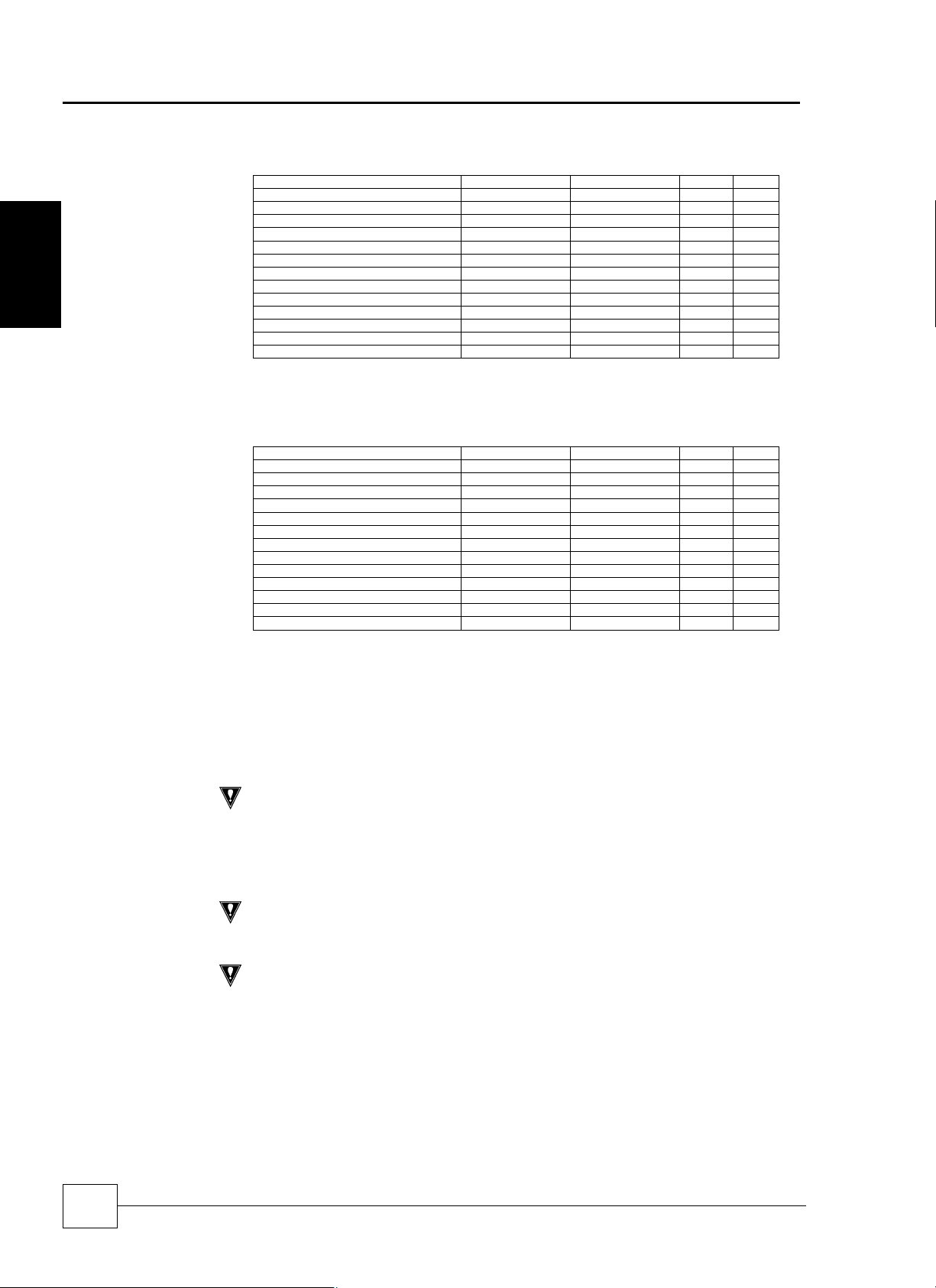
Precision Air Conditioning
Humidifier Bottle
IMPORTANT
The water supply should conform to Local Water Regulations and within the
IMPORTANT
Ensure the union between the humidifier assembly and supply hose is fully
CAUTION
It is recommended that a shut off valve and a mecha
nical strainer be fitted to the
Water Conductivity
SmartCoolTM - D
Information
Installation
Precision Air Conditioning
Limit Values for the supply water with Medium to High conductivity in an immersed
electrode humidifier.
Min Max
Hydrogen ions pH 7 8.5
Specific conductivity at 20°C σR, 20°C μS/cm 300 1250
Total dissolved solids TDS mg/l (1) (1)
Dry residue at 180°C R180 mg/l (1) (1)
Total hardness TH mg/l CaCO3 100(2) 400
Temporary hardness mg/l CaCO3 60(3) 300
Iron + Manganese mg/l Fe + Mn 0 0.2
Chlorides ppm- Cl 0 30
Silica mg/l SiO2 0 20
Residual chlorine mg/l Cl 0 0.2
Calcium sulphate mg/l CaSO4 0 100
Metallic impurities mg/l 0 0
Solvents, diluents, soaps, lubricants mg/l 0 0
(1) Values depending on specific conductivity; in general: TDS ≅ 0.93 * σ20; R180 ≅ 0.65 * σ20
(2) not lower than 200% of the chloride content in mg/l of Cl(3) not lower than 300% of the chloride content in mg/l of Cl-
Limit Values for the supply water with Medium to Low conductivity in an immersed
electrode humidifier
Min Max
Hydrogen ions pH 7 8.5
Specific conductivity at 20°C σR, 20°C μS/cm 125 500
Total dissolved solids TDS mg/l (1) (1)
Dry residue at 180°C R180 mg/l (1) (1)
Total hardness TH mg/l CaCO3 50(2) 250
Temporary hardness mg/l CaCO3 30(3) 150
Iron + Manganese mg/l Fe + Mn 0 0.2
Chlorides ppm- Cl 0 20
Silica mg/l SiO2 0 20
Residual chlorine mg/l Cl 0 0.2
Calcium sulphate mg/l CaSO4 0 60
Metallic impurities mg/l 0 0
Solvents, diluents, soaps, lubricants mg/l 0 0
(1) Values depending on specific conductivity; in general: TDS ≅ 0.93 * σ20; R180 ≅ 0.65 * σ20
(2) not lower than 200% of the chloride content in mg/l of Cl(3) not lower than 300% of the chloride content in mg/l of Cl-
Warning: no relation can be demonstrated between water hardness and
conductivity.
IMPORTANT WARNING: do not treat water with softeners!
This could cause corrosion of the electrodes or the formation of foam, leading to
potential operating problems or failures.
30
following guidelines:
Supply water pressure between 1.0 barg to 8.0 barg, > 8.0 bar a pressure reducing valve
should be fitted.
A minimum flow rate of 1.21 l/min is required.
The humidifier inlet is fitted with a braided flexible hose, having 3/4” BSPF connection.
tightened. Any looseness, misalignment or damage to the union can lead to
water leakage.
water supply prior to the humidifier assembly.
As standard the humidifier is fitted with the standard conductivity cylinder which covers
the majority of water supplies. Low and high conductivity options can be specified at
order.
Installation, Maintenance and Commissioning Manual :6877419 02/2013

Precision Air Conditioning
Installation, Maintenance and Commissioning Manual :6877419 02/2013
Water Conductivity &
CAUTION
The supply water pressure
to the humidifier assembly must
be between 1
- 8 barg.
Safe Operation o
f
CAUTION
An overflow weir is incorporated in the common fill/drain tundish. Any pressure
IMPORTANT
It is MOST IMPORTANT that the steam distribution pipe is not damage
d or kinked at
Precision Air Conditioning
3 different cylinders shall be available which correspond to the supply water conductivity.
Cylinder Type
The cylinder type shall be matched with the standard conductivity of the supply water to
ensure optimum performance and increases the life span of the cylinder.
1 Low Conductivity (Soft Water) 100 to 350 mS/cm
2 Standard Conductivity (Moderate/Hard Water) 350 to 750 mS/cm
3 High Conductivity (Very Hard Water) 750 to 1250 mS/cm
Conductivity is a measure of the ability of water to pass an electric current, measured in micro
Siemens / centimetre (mS/cm).
As standard the humidifier shall be fitted with the standard conductivity cylinder which shall
cover the majority of water supplies. Where the water conductivity is known, please specify
at order. For further details please contact Airedale.
To protect the humidifier bottle from dangerous pressures in event of the steam supply
Humidifier
pipe becoming blocked, a tundish is installed between the water inlet solenoid and the
cylinder to act as a reservoir and to feed water to the humidifier inlet manifold as required.
SmartCoolTM – D
Installation
build up in the cylinder would be allowed to vent through the tundish to
atmosphere.
any time to avoid the risk of unacceptably high pressure building up in the electrode
bottle
31

Precision Air Conditioning
Condensate
Drain Pipework
Condensate
Pump
IMPORTANT
Use only 10mm (3/8”) copper tube when connecting the discharge
stub to the
B C D
Condensate
Condensate Pump
Water Leak Detector T
ape
0 2
4
6
8
10
5 7
9
11 13 15
SmartCoolTM - D
Installation Data
Installation
Precision Air Conditioning
condensate pump. The discharge line from the pump should rise no more than 6m
vertically and no more than 8m in total length before being interrupted with a swan
neck air break and tundish.
When calculating the total head required and factor into the drain pipework design.
Suitable roding positions should be incorporated particularly if the run is long.
A Condensate Pump
B Condensate pump discharge line; 10mm
(3/8”) copper tube; maximum vertical run
6m, maximum TOTAL run 8m
C Swan Neck with Tundish
D Drain line from Tundish, > 10mm (3/8”)
tube (MUST BE copper tube when
A
coupled with humidifier drain), minimum
fall 1 : 20
&
Humidifier
(Optional Extra)
Performance
All drain trays are fitted with their own trap assembly.
Condensate drain may be run to waste via ordinary plastic waste pipe.
Humidifier drain may be run to waste via pipe suitable for liquid temperatures of 100°C.
All drain pipework operating under gravity should be sloped away from the equipment and
the gradient should be made as steep as possible.
Suitable roding positions should be incorporated particularly if the run is long.
The following graphs illustrate the TOTAL static (head) pressure available. The system
horizontal pipe losses and vertical lift should be factored in when calculating the
condensate pump performance.
12
Head (m)
Pump Flow Rate (l/min)
The water detector tape should be insulated at the ends. This will avoid nuisance
alarms should un-insulated ends touch any conductive material.
32
Installation, Maintenance and Commissioning Manual :6877419 02/2013

Precision Air Conditioning
Installation, Maintenance and Commissioning Manual :6877419 02/2013
Location
Fitting Instructions
Pipework
Pipe Clips
Condensate Drain Priming
Checking for Leaks
Condensate Pump
Precision Air Conditioning
The condensate pump is located within the base of the unit on the right hand side.
However if a humidifier is fitted as an integral part of the machine the condensate pump
is mounted under the unit. The pump is supplied loose with full instruction for onsite
fitment.
SmartCoolTM – D
Operation
Condensate Pump
Support Bracket
Assembly
The location of the pump assembly
depends on the type of Floorstand. Front
or Rear discharge air.
The pump is positioned near to the outlet
of the Floorstand air discharge allowing
unrestricted condensate flow. (Front or
Rear of the unit)
The pipework supplied loose can be cut to allow unrestricted condensate flow from the
condensate and humidifier drain. The pipework fitted is connected to the condensate
drain with a compression fitting. The pipework locates into the pump through grommet
holes.
The flexible pipework clips are to be tightened sufficiently to maintain a water tight seal
during unit operation. Do not over tighten as this can damage the condensate hose.
The drain tray must be primed with water to ensure that the trap is full before the unit is
operated.
Check that the pipework and condensate drain tray do not leak water.
Check that the condensate pump operates correctly and that the maximum pumping
head of 10.8 m is not exceeded. Ensure that a tundish is used to ensure free flow of
condensate to customer drains and therefore cannot back feed when the pump is
turned off.
Installation
33

Precision Air Conditioning
Constant Pressure
Constant Air Volume
SmartCoolTM - D
Control
Installation
Precision Air Conditioning
Constant pressure control is a method of controlling air pressure within a space, such as
a floor void or a duct. The air pressure is controlled using a variable speed fan that is
modulated to maintain a given set point.
Constant pressure control monitors the air pressure differential between two points. In a
typical application (shown below) the pressure under the raised floor (red) is compared
to the room pressure (blue).
Room
Pressure
Underfloor
pressure
The two pressure points, positive and negative, are routed back to an air differential
pressure sensor inside the CRAC unit. The value from the air pressure sensor is
compared to the set point and a fan speed demand is generated, to maintain the
required pressure differential.
It is the responsibility of the installer to fit the air pressure sensor(s). The sensor shall be
located under the false floor with the 6mm flamtronix tubing routed back into the control
panel of the unit (the tubing must not be obstructed /damaged to ensure accurate
pressure control).
The constant pressure system shall be commissioned by Airedale following routing of
tubing from the pressure diffuser and the unit.
A maximum of 8m/s air velocity is allowed at the diffuser so consideration must be made
when locating the diffuser.
Constant air volume is a method of automatically adjusting the unit fan speed to deliver a
specific air volume.
When faced with a change in system resistance, the fan speed modulates to obtain the
air volume set point.
Constant air volume monitors the air pressure differential between two points. These two
pressure points, positive and negative, are routed back to an air differential pressure
sensor inside the unit
34
Installation, Maintenance and Commissioning Manual :6877419 02/2013

Precision Air Conditioning
Installation, Maintenance and Commissioning Manual :6877419 02/2013
Precision Air Conditioning
Fan Speeds
Model
Fan
Selection
Standard
Air
Volume
(m³/s)
DeHum
Air
Volume
(m³/s)
Max Air
Volume
(m³/s)
SmartCoolTM – D
External Static Pressure (Pa)
25
50
75
100
125
150
175
200
225
250
275
300
SC19D065-
C000-0
SC19D075-
C000-0
SC19D090-
C000-0
SC19D100-
C000-0
SC19D105-
C000-0
SC25D090-
C000-0
EC
SC19D
STD
EC
SC19D
UPG
EC
SC19D
STD
EC
SC19D
UPG
EC
SC19D
STD
EC
SC19D
UPG
EC SL19D
STD
EC SL19D
UPG
EC SL19D
STD
EC SL19D
UPG
AC
SC25D
STD
EC
SC25D
STD
EC
SC25D
UPG
3.66
1.83 3.7 4.0 4.3 4.6 4.9 5.2 5.5 5.8 6.1 6.4 6.7 7.0
5.50 - - - - - - - - - - - -
3.66 6.5 6.6 6.8 6.9 7.1 7.3 7.4 7.6 7.7 7.9 8.0 8.2
1.83 3.4 3.7 4.0 4.3 4.6 4.9 5.2 5.4 5.6 5.8 6.1 6.3
5.50 9.6 9.7 9.8 9.9 - - - - - - - -
4.22
2.11 4.2 4.4 4.7 5.0 5.3 5.6 5.8 6.1 6.4 6.7 7.0 7.2
5.50 - - - - - - - - - - - -
4.22 7.4 7.6 7.7 7.9 8.0 8.1 8.3 8.4 8.5 8.7 8.8 8.9
2.11 3.7 4.0 4.4 4.7 5.0 5.2 5.4 5.6 5.9 6.1 6.3 6.5
5.50 9.6 9.7 9.8 9.9 - - - - - - - -
5.06
2.53 4.8 5.1 5.4 5.6 5.9 6.1 6.4 6.7 6.9 7.2 7.3 7.5
5.50 - - - - - - - - - - - -
5.06 8.9 9.0 9.1 9.2 9.4 9.5 9.6 9.7 9.8 9.9 - -
2.53 4.4 4.8 5.1 5.3 5.5 5.7 5.9 6.1 6.3 6.5 6.7 6.9
5.50 9.6 9.7 9.8 9.9 - - - - - - - -
5.06
2.53 4.8 5.0 5.3 5.6 5.8 6.1 6.3 6.6 6.9 7.1 7.3 7.5
5.70 - - - - - - - - - - - -
5.06 8.8 8.9 9.0 9.2 9.3 9.4 9.5 9.6 9.7 9.8 9.9 -
2.53 4.3 4.7 5.1 5.3 5.5 5.7 5.9 6.1 6.3 6.5 6.7 6.9
5.70 9.9 10 - - - - - - - - - -
5.06
2.53 4.9 5.2 5.4 5.7 5.9 6.2 6.5 6.7 7.0 7.2 7.4 7.6
5.70 - - - - - - - - - - - -
5.06 9.0 9.1 9.2 9.3 9.4 9.5 9.6 9.8 9.9
2.53 4.5 4.9 5.1 5.3 5.5 5.7 6.0 6.2 6.4 6.6 6.8 7.0
5.70 - - - - - - - - - - - -
5.32
2.66 4.2 4.5 4.9 5.2 5.5 5.7 5.9 6.1 6.3 6.6 6.8 7.0
7.75 - - - - - - - - - - - -
5.32 7.5 7.7 7.8 8.0 8.2 8.3 8.5 8.7 8.8 9.0 9.2 9.3
2.66 4.0 4.3 4.6 4.9 5.2 5.5 5.8 6.1 6.4 6.7 7.0 7.2
7.75 - - - - - - - - - - - -
5.32 7.0 7.1 7.3 7.4 7.6 7.7 7.9 8.0 8.2 8.3 8.5 8.6
2.66 3.7 4.0 4.3 4.6 4.9 5.2 5.4 5.6 5.8 6.0 6.3 6.5
7.75 9.9 - - - - - - - - - - -
6.9 7.2 7.3 7.5 7.7 7.8 8.0 8.2 8.3 8.5 8.6 8.8
7.9 8.1 8.2 8.4 8.5 8.7 8.8 9.0 9.2 9.3 9.5 9.6
9.4 9.6 9.7 9.9 - - - - - - - -
9.3 9.5 9.6 9.8 9.9 - - - - - - -
9.5 9.7 9.8
8.0 8.2 8.4 8.6 8.7 8.9 9.1 9.2 9.4 9.6 9.8 9.9
10.
- - - - - - - -
0
10.
- -
0
Installation
35

Precision Air Conditioning
SmartCoolTM - D
Model
SC25D100-
C000-0
Installation
SC25D110-
C000-0
SC31D110-
C000-0
SC31D130-
C000-0
SC31D150-
C000-0
Model
Fan
Selection
AC
SC25D
STD
EC
SC25D
STD
EC
SC25D
UPG
AC
SC25D
STD
EC
SC25D
STD
EC
SC25D
UPG
EC
SC31D
UPG
EC
SC31D
UPG
EC
SC31D
UPG
Fan
Selection
Precision Air Conditioning
Standard
Air
Volume
(m³/s)
5.91
2.96 4.6 5.0 5.3 5.5 5.8 6.0 6.2 6.4 6.7 6.9 7.1 7.3
7.75 - - - - - - - - - - - -
5.91 8.2 8.4 8.5 8.7 8.9 9.0 9.2 9.3 9.5 9.7 9.8 -
2.96 4.3 4.6 4.9 5.2 5.5 5.8 6.1 6.4 6.6 6.9 7.2 7.4
7.75 - - - - - - - - - - - -
5.91 7.7 7.8 7.9 8.1 8.2 8.4 8.5 8.6 8.8 8.9 9.1 9.2
2.96 4.0 4.3 4.6 4.9 5.2 5.4 5.6 5.8 6.0 6.3 6.5 6.7
7.75 9.9 - - - - - - - - - - -
6.50
3.25 5.1 5.4 5.6 5.9 6.1 6.3 6.5 6.8 7.0 7.2 7.4 7.6
7.75 - - - - - - - - - - - -
6.50 9.0 9.1 9.3 9.4 9.6 9.8 9.9 - - - - -
3.25 4.7 5.0 5.3 5.5 5.8 6.1 6.4 6.6 6.9 7.2 7.4 7.5
7.75 - - - - - - - - - - - -
6.50 8.4 8.5 8.7 8.8 8.9 9.1 9.2 9.3 9.4 9.6 9..7 9.8
3.25 4.3 4.6 5.0 5.2 5.4 5.6 5.8 6.1 6.3 6.5 6.7 6.9
7.75 9.9 - - - - - - - - - - -
5.82
2.91 3.8 4.1 4.4 4.7 5.0 5.2 5.4 5.7 5.9 6.1 6.3 6.5
8.00 9.9
6.88
3.44 4.3 4.7 5.0 5.2 5.4 5.6 5.9 6.1 6.3 6.5 6.7 6.9
8.00 9.9 10 - - - - - - - - - -
7.94
3.97 5.1 5.3 5.5 5.7 5.9 6.1 6.3 6.5 6.7 6.9 7.1 7.3
8.00 9.9 10 - - - - - - - - - -
Standard Air
Volume
(m³/s)
DeHum
Air
Volume
(m³/s)
DeHum Air
Volume
(m³/s)
Max Air
Volume
(m³/s)
25
50
8.8 9.0 9.2 9.3 9.5 9.7 9.8 - - - - -
9.7 9.9 - - - - - - - - - -
7.2 7.4 7.6 7.7 7.8 8.0 8.1 8.3 8.4 8.6 8.7 8.8
10.
- - - - - - - - - -
0
8.6 8.7 8.8 8.9 9.0 9.2 9.3 9.4 9.5 9.7 9.8 9.9
9.8 9.9 - - - - - - - - - -
Max Air
Volume
(m³/s)
25
External Static Pressure (Pa)
75
100
125
External Static Pressure (Pa)
50
75
100
150
175
200
225
250
275
125
150
175
200
225
250
300
275
300
SC19D033-
C0C0-0
SC19D038-
C0C0-0
SC19D045-
C0C0-0
EC SC19D
STD
EC SC19D
UPG
EC SC19D
STD
EC SC19D
UPG
EC SC19D
STD
EC SC19D
UPG
3.71
1.86 3.8 4.1 4.4 4.6 4.9 5.2 5.5 5.8 6.1 6.4 6.7 7.0
5.50 - - - - - - - - - - - -
3.71 6.5 6.7 6.9 7.0 7.2 7.4 7.5 7.7 7.8 7.9 8.1 8.2
1.86 3.4 3.7 4.0 4.4 4.7 5.0 5.2 5.4 5.6 5.9 6.1 6.3
5.50 9.6 9.7 9.8 9.9 - - - - - - - -
4.27
2.14 4.2 4.5 4.8 5.0 5.3 5.6 5.9 6.2 6.4 6.7 7.0 7.2
5.50 - - - - - - - - - - - -
4.27 7.6 7.7 7.8 8.0 8.1 8.2 8.4 8.5 8.6 8.7 8.9 9.0
2.14 3.7 4.1 4.4 4.7 5.0 5.2 5.5 5.7 5.9 6.1 6.3 6.5
5.50 9.6 9.7 9.8 9.9 - - - - - - - -
5.06
2.53 4.8 5.1 5.4 5.6 5.9 6.1 6.4 6.7 6.9 7.2 7.3 7.5
5.50 - - - - - - - - - - - -
5.06 8.9 9.0 9.1 9.2 9.4 9.5 9.6 9.7 9.8 9.9 - -
2.53 4.4 4.8 5.1 5.3 5.5 5.7 5.9 6.1 6.3 6.5 6.7 6.9
5.50 9.6 9.7 9.8 9.9 - - - - - - - -
7.1 7.2 7.4 7.6 7.7 7.9 8.1 8.2 8.4 8.6 8.7 8.9
8.0 8.2 8..3 8.5 8.6 8.8 8.9 9.1 9.2 9.4 9.5 9.7
9.4 9.6 9.7 9.9 - - - - - - - -
36
Installation, Maintenance and Commissioning Manual :6877419 02/2013

Precision Air Conditioning
Installation, Maintenance and Commissioning Manual :6877419 02/2013
Precision Air Conditioning
Model
Fan
Selection
Standard
Air
Volume
(m³/s)
DeHum
Air
Volume
(m³/s)
Max Air
Volume
(m³/s)
25
SmartCoolTM – D
External Static Pressure (Pa)
50
75
100
125
150
175
200
225
250
275
300
SC25D045-
C0C0-0
SC25D050-
C0C0-0
SC25D055-
C0C0-0
SC31D055-
C0C0-0
SC31D065-
C0C0-0
SC31D075-
C0C0-0
AC
SC25D
STD
EC
SC25D
STD
EC
SC25D
UPG
AC
SC25D
STD
EC
SC25D
STD
EC
SC25D
UPG
AC
SC25D
STD
EC
SC25D
STD
EC
SC25D
UPG
EC
SC31D
UPG
EC
SC31D
UPG
EC
SC31D
UPG
5.32
5.32 7.5 7.7 7.8 8.0 8.2 8.3 8.5 8.7 8.8 9.0 9.2 9.3
5.32 7.0 7.1 7.3 7.4 7.6 7.7 7.9 8.0 8.2 8.3 8.5 8.6
5.91
5.91 8.2 8.4 8.5 8.7 8.9 9.0 9.2 9.3 9.5 9.7 9.8 -
5.91 7.7 7.8 7.9 8.1 8.2 8.4 8.5 8.6 8.8 8.9 9.1 9.2
6.50
6.50 9.0 9.1 9.3 9.4 9.6 9.8 9.9 - - - - -
6.50 8.4 8.5 8.7 8.8 8.9 9.1 9.2 9.3 9.4 9.6 9.7 9.8
5.82
6.88
7.94
2.66 4.2 4.5 4.9 5.2 5.5 5.7 5.9 6.1 6.3 6.6 6.8 7.0
7.75 - - - - - - - - - - - -
2.66 4.0 4.3 4.6 4.9 5.2 5.5 5.8 6.1 6.4 6.7 7.0 7.2
7.75 - - - - - - - - - - - -
2.66 3.7 4.0 4.3 4.6 4.9 5.2 5.4 5.6 5.8 6.0 6.3 6.5
7.75 9.9 - - - - - - - - - - -
2.96 4.6 5.0 5.3 5.5 5.8 6.0 6.2 6.4 6.7 6.9 7.1 7.3
7.75 - - - - - - - - - - - -
2.96 4.3 4.6 4.9 5.2 5.5 5.8 6.1 6.4 6.6 6.9 7.2 7.4
7.75 - - - - - - - - - - - -
2.96 4.0 4.3 4.6 4.9 5.2 5.4 5.6 5.8 6.0 6.3 6.5 6.7
7.75 9.9 - - - - - - - - - - -
3.25 5.1 5.4 5.6 5.9 6.1 6.3 6.5 6.8 7.0 7.2 7.4 7.6
7.75 - - - - - - - - - - - -
3.25 4.7 5.0 5.3 5.5 5.8 6.1 6.4 6.6 6.9 7.2 7.4 7.5
7.75 - - - - - - - - - - - -
3.25 4.3 4.6 5.0 5.2 5.4 5.6 5.8 6.1 6.3 6.5 6.7 6.9
7.75 9.9 - - - - - - - - - - -
2.91 3.8 4.1 4.4 4.7 5.0 5.2 5.4 5.7 5.9 6.1 6.3 6.5
8.00 9.9 10 - - - - - - - - - -
3.44 4.3 4.7 5.0 5.2 5.4 5.6 5.9 6.1 6.3 6.5 6.7 6.9
8.00 9.9 10 - - - - - - - - - -
3.97 5.1 5.3 5.5 5.7 5.9 6.1 6.3 6.5 6.7 6.9 7.1 7.3
8.00 9.9 10 - - - - - - - - - -
8.0 8.2 8.4 8.6 8.7 8.9 9.1 9.2 9.4 9.6 9.8 9.9
8.8 9.0 9.2 9.3 9.5 9.7 9.8 - - - - -
9.7 9.9 - - - - - - - - - -
7.2 7.4 7.6 7.7 7.8 8.0 8.1 8.3 8.4 8.6 8.7 8.8
8.6 8.7 8.8 8.9 9.0 9.2 9.3 9.4 9.5 9.7 9.8 9.9
9.8 9.9 - - - - - - - - - -
Installation
37

Precision Air Conditioning
SmartCoolTM - D
Model
SC19D055-X2X2-0
Installation
SC19D070-X2X2-0
SC19D080-X2X2-0
SC25D080-X2X2-0
Fan
Selectio
n
EC
SC19D
STD
EC
SC19D
UPG
EC
SC19D
STD
EC
SC19D
UPG
EC
SC19D
STD
EC
SC19D
UPG
AC
SC25D
STD
EC
SC25D
STD
EC
SC25D
UPG
Precision Air Conditioning
Standard
Air
Volume
(m³/s)
3.48
1.74 3.6 3.9 4.2 4.5 4.8 5.1 5.4 5.7 6.0 6.3 6.6 6.9
5.50 - - - - - - - - - - - -
3.48 6.2 6.4 6.6 6.7 6.9 7.0 7.2 7.4 7.5 7.7 7.8 8.0
1.74 3.3 3.6 3.9 4.2 4.5 4.8 5.1 5.3 5.5 5.8 6.0 6.2
5.50 9.6 9.7 9.8 9.9 - - - - - - - -
4.43
2.22 4.3 4.6 4.9 5.2 5.4 5.7 6.0 6.3 6.5 6.8 7.1 7.3
5.50 - - - - - - - - - - - -
4.43 7.8 8.0 8.1 8.2 8.3 8.5 8.6 8.7 8.8 9.0 9.1 9.2
2.22 3.8 4.2 4.5 4.8 5.1 5.3 5.5 5.8 6.0 6.2 6.4 6.6
5.50 9.6 9.7 9.8 9.9 - - - - - - - -
5.06
2.53 4.8 5.1 5.4 5.6 5.9 6.1 6.4 6.7 6.9 7.2 7.3 7.5
5.50 - - - - - - - - - - - -
5.06 8.9 9.0 9.1 9.2 9.4 9.5 9.6 9.7 9.8 9.9 - -
2.53 4.4 4.8 5.1 5.3 5.5 5.7 5.9 6.1 6.3 6.5 6.7 6.9
5.50 9.6 9.7 9.8 9.9 - - - - - - - -
5.20
2.60 4.1 4.4 4.8 5.1 5.4 5.6 5.8 6.1 6.3 6.5 6.7 6.9
7.75 - - - - - - - - - - - -
5.20 7.3 7.5 7.7 7.8 8.0 8.2 8.4 8.5 8.7 8.9 9.0 9.2
2.60 3.9 4.2 4.5 4.8 5.1 5.4 5.7 6.0 6.3 6.6 6.9 7.2
7.75 - - - - - - - - - - - -
5.20 6.8 7.0 7.1 7.3 7.5 7.6 7.8 7.9 8.1 8.2 8.4 8.5
2.60 3.6 3.9 4.2 4.6 4.9 5.1 5.3 5.6 5.8 6.0 6.2 6.4
7.75 9.9 - - - - - - - - - - -
DeHum
Air
Volume
(m³/s)
Max Air
Volume
(m³/s)
25
50
6.4 6.7 7.1 7.2 7.4 7.6 7.7 7.9 8.1 8.2 8.4 8.6
8.3 8.4 8.6 8.7 8.9 9.0 9.2 9.3 9.5 9.6 9.8
9.4 9.6 9.7 9.9 - - - - - - - -
7.8 8.1 8.3 8.4 8.6 8.8 8.9 9.1 9.3 9.4 9.6 9.8
External Static Pressure (Pa)
75
100
125
150
175
200
225
250
275
300
10.
0
38
Installation, Maintenance and Commissioning Manual :6877419 02/2013

Precision Air Conditioning
Installation, Maintenance and Commissioning Manual :6877419 02/2013
Precision Air Conditioning
Model
SC25D090-X2X2-0
SC25D100-X2X2-0
SC31D100-X2X2-0
SC31D120-X2X2-0
SC31D130-X2X2-0
Fan
Selection
AC SC25D
STD
EC SC25D
STD
EC SC25D
UPG
AC SC25D
STD
EC SC25D
STD
EC SC25D
UPG
EC SC31D
UPG
EC SC31D
UPG
EC SC31D
UPG
Standard
Air
Volume
(m³/s)
5.85
5.85 8.1 8.3 8.5 8.6 8.8 8.9 9.1 9.3 9.4 9.6 9.8
5.85 7.6 7.7 7.9 8.0 8.2 8.3 8.4 8.6 8.7 8.9 9.0 9.1
6.50
6.50 9.0 9.1 9.3 9.4 9.6 9.8 9.9 - - - - -
6.50 8.4 8.5 8.7 8.8 8.9 9.1 9.2 9.3 9.4 9.6 9.7 9.8
6.11
7.33
7.94
DeHum
Volume
(m³/s)
2.93 4.6 4.9 5.3 5.5 5.7 6.0 6.2 6.4 6.6 6.8 7.1 7.3
7.75 - - - - - - - - - - - -
2.93 4.3 4.6 4.9 5.2 5.5 5.7 6.0 6.3 6.6 6.9 7.1 7.3
7.75 - - - - - - - - - - - -
2.93 3.9 4.3 4.6 4.9 5.1 5.4 5.6 5.8 6.0 6.2 6.4 6.7
7.75 9.9 - - - - - - - - - - -
3.25 5.1 5.4 5.6 5.9 6.1 6.3 6.5 6.8 7.0 7.2 7.4 7.6
7.75 - - - - - - - - - - - -
3.25 4.7 5.0 5.3 5.5 5.8 6.1 6.4 6.6 6.9 7.2 7.4 7.5
7.75 - - - - - - - - - - - -
3.25 4.3 4.6 5.0 5.2 5.4 5.6 5.8 6.1 6.3 6.5 6.7 6.9
7.75 9.9 - - - - - - - - - - -
3.06 3.9 4.2 4.5 4.8 5.1 5.3 5.5 5.8 6.0 6.2 6.4 6.6
8.00 9.9 10 - - - - - - - - - -
3.67 4.7 5.0 5.2 5.4 5.6 5.8 6.0 6.3 6.5 6.7 6.9 7.1
8.00 9.9 10 - - - - - - - - - -
3.97 5.1 5.3 5.5 5.7 5.9 6.1 6.3 6.5 6.7 6.9 7.1 7.3
8.00 9.9
Air
Max Air
Volume
(m³/s)
SmartCoolTM – D
External Static Pressure (Pa)
25
50
75
100
125
150
175
200
225
250
275
8.8 8.9 9.1 9.3 9.4 9.6 9.8 9.9 - - - -
10.
0
9.7 9.9 - - - - - - - - - -
7.6 7.8 7.9 8.0 8.2 8.3 8.4 8.6 8.7 8.8 9.0 9.1
9.1 9.2 9.3 9.4 9.5 9.7 9.8 9.9
9.8 9.9 - - - - - - - - - -
10.
- - - - - - - - - -
0
10.
0
- - -
300
Installation
39

Precision Air Conditioning
SmartCoolTM - D
Model
SC19D055-W2W2-0
Installation
SC19D070-W2W2-0
SC19D080-W2W2-0
SC25D080-W2W2-0
SC25D090-W2W2-0
SC25D100-W2W2-0
SC31D100-W2W2-0
SC31D120-W2W2-0
SC31D130-W2W2-0
Fan
Selection
EC
SC19D
STD
EC
SC19D
UPG
EC
SC19D
STD
EC
SC19D
UPG
EC
SC19D
STD
EC
SC19D
UPG
AC
SC25D
STD
EC
SC25D
STD
EC
SC25D
UPG
AC
SC25D
STD
EC
SC25D
STD
EC
SC25D
UPG
AC
SC25D
STD
EC
SC25D
STD
EC
SC25D
UPG
EC
SC31D
UPG
EC
SC31D
UPG
EC
SC31D
UPG
Precision Air Conditioning
Standard
Air
Volume
(m³/s)
3.48
3.48 6.2 6.4 6.6 6.7 6.9 7.0 7.2 7.4 7.5 7.7 7.8 8.0
4.43
4.43 7.8 8.0 8.1 8.2 8.3 8.5 8.6 8.7 8.8 9.0 9.1 9.2
5.06
5.06 8.9 9.0 9.1 9.2 9.4 9.5 9.6 9.7 9.8 9.9 - -
5.20
5.20 7.3 7.5 7.7 7.8 8.0 8.2 8.4 8.5 8.7 8.9 9.0 9.2
5.20 6.8 7.0 7.1 7.3 7.5 7.6 7.8 7.9 8.1 8.2 8.4 8.5
5.85
5.85 8.1 8.3 8.5 8.6 8.8 8.9 9.1 9.3 9.4 9.6 9.8
5.85 7.6 7.7 7.9 8.0 8.2 8.3 8.4 8.6 8.7 8.9 9.0 9.1
6.50
6.50 9.0 9.1 9.3 9.4 9.6 9.8 9.9 - - - - -
6.50 8.4 8.5 8.7 8.8 8.9 9.1 9.2 9.3 9.4 9.6 9.7 9.8
6.11
7.33
7.94
DeHum
Air
Volume
(m³/s)
1.74 3.6 3.9 4.2 4.5 4.8 5.1 5.4 5.7 6.0 6.3 6.6 6.9
5.50 - - - - - - - - - - - -
1.74 3.3 3.6 3.9 4.2 4.5 4.8 5.1 5.3 5.5 5.8 6.0 6.2
5.50 9.6 9.7 9.8 9.9 - - - - - - - -
2.22 4.3 4.6 4.9 5.2 5.4 5.7 6.0 6.3 6.5 6.8 7.1 7.3
5.50 - - - - - - - - - - - -
2.22 3.8 4.2 4.5 4.8 5.1 5.3 5.5 5.8 6.0 6.2 6.4 6.6
5.50 9.6 9.7 9.8 9.9 - - - - - - - -
2.53 4.8 5.1 5.4 5.6 5.9 6.1 6.4 6.7 6.9 7.2 7.3 7.5
5.50 - - - - - - - - - - - -
2.53 4.4 4.8 5.1 5.3 5.5 5.7 5.9 6.1 6.3 6.5 6.7 6.9
5.50 9.6 9.7 9.8 9.9 - - - - - - - -
2.60 4.1 4.4 4.8 5.1 5.4 5.6 5.8 6.1 6.3 6.5 6.7 6.9
7.75 - - - - - - - - - - - -
2.60 3.9 4.2 4.5 4.8 5.1 5.4 5.7 6.0 6.3 6.6 6.9 7.2
7.75 - - - - - - - - - - - -
2.60 3.6 3.9 4.2 4.6 4.9 5.1 5.3 5.6 5.8 6.0 6.2 6.4
7.75 9.9 - - - - - - - - - - -
2.93 4.6 4.9 5.3 5.5 5.7 6.0 6.2 6.4 6.6 6.8 7.1 7.3
7.75 - - - - - - - - - - - -
2.93 4.3 4.6 4.9 5.2 5.5 5.7 6.0 6.3 6.6 6.9 7.1 7.3
7.75 - - - - - - - - - - - -
2.93 3.9 4.3 4.6 4.9 5.1 5.4 5.6 5.8 6.0 6.2 6.4 6.7
7.75 9.9 - - - - - - - - - - -
3.25 5.1 5.4 5.6 5.9 6.1 6.3 6.5 6.8 7.0 7.2 7.4 7.6
7.75 - - - - - - - - - - - -
3.25 4.7 5.0 5.3 5.5 5.8 6.1 6.4 6.6 6.9 7.2 7.4 7.5
7.75 - - - - - - - - - - - -
3.25 4.3 4.6 5.0 5.2 5.4 5.6 5.8 6.1 6.3 6.5 6.7 6.9
7.75 9.9 - - - - - - - - - - -
3.06 3.9 4.2 4.5 4.8 5.1 5.3 5.5 5.8 6.0 6.2 6.4 6.6
8.00 9.9
3.67 4.7 5.0 5.2 5.4 5.6 5.8 6.0 6.3 6.5 6.7 6.9 7.1
8.00 9.9
3.97 5.1 5.3 5.5 5.7 5.9 6.1 6.3 6.5 6.7 6.9 7.1 7.3
8.00 9.9
Max Air
Volume
(m³/s)
25
50
6.4 6.7 7.1 7.2 7.4 7.6 7.7 7.9 8.1 8.2 8.4 8.6
8.3 8.4 8.6 8.7 8.9 9.0 9.2 9.3 9.5 9.6 9.8
9.4 9.6 9.7 9.9 - - - - - - - -
7.8 8.1 8.3 8.4 8.6 8.8 8.9 9.1 9.3 9.4 9.6 9.8
8.8 8.9 9.1 9.3 9.4 9.6 9.8 9.9 - - - -
9.7 9.9 - - - - - - - - - -
7.6 7.8 7.9 8.0 8.2 8.3 8.4 8.6 8.7 8.8 9.0 9.1
10.
0
9.1 9.2 9.3 9.4 9.5 9.7 9.8 9.9
10.
0
9.8 9.9 - - - - - - - - - -
10.
0
External Static Pressure (Pa)
75
100
125
150
175
200
225
250
275
- - - - - - - - - -
10.
- - -
0
- - - - - - - - - -
- - - - - - - - - -
300
10.
0
10.
0
40
Installation, Maintenance and Commissioning Manual :6877419 02/2013

Precision Air Conditioning
Installation, Maintenance and Commissioning Manual :6877419 02/2013
Precision Air Conditioning
Model
SC19D033-X2C0-0
SC19D038-X2C0-0
SC19D045-X2C0-0
SC19D064-X2C0-0
SC19D070-X2C0-0
SC19D076-X2C0-0
Fan
Selection
EC
SC19D
STD
EC
SC19D
UPG
EC
SC19D
STD
EC
SC19D
UPG
EC
SC19D
STD
EC
SC19D
UPG
EC
SC19D
STD
EC
SC19D
UPG
EC
SC19D
STD
EC
SC19D
UPG
EC
SC19D
STD
EC
SC19D
UPG
Standard
Air
Volume
(m³/s)
3.71
3.71 6.5 6.7 6.9 7.0 7.2 7.4 7.5 7.7 7.8 7.9 8.1 8.2
4.27
4.27 7.6 7.7 7.8 8.0 8.1 8.2 8.4 8.5 8.6 8.7 8.9 9.0
5.06
5.06 8.9 9.0 9.1 9.2 9.4 9.5 9.6 9.7 9.8 9.9 - -
5.06
5.06 8.9 9.0 9.1 9.2 9.4 9.5 9.6 9.7 9.8 9.9 - -
5.06
5.06 8.9 9.0 9.1 9.2 9.4 9.5 9.6 9.7 9.8 9.9 - -
5.06
5.06 8.9 9.0 9.1 9.2 9.4 9.5 9.6 9.7 9.8 9.9 - -
DeHum
Air
Volume
(m³/s)
1.86 3.8 4.1 4.4 4.6 4.9 5.2 5.5 5.8 6.1 6.4 6.7 7.0
5.50 - - - - - - - - - - - -
1.86 3.4 3.7 4.0 4.4 4.7 5.0 5.2 5.4 5.6 5.9 6.1 6.3
5.50 9.6 9.7 9.8 9.9 - - - - - - - -
2.14 4.2 4.5 4.8 5.0 5.3 5.6 5.9 6.2 6.4 6.7 7.0 7.2
5.50 - - - - - - - - - - - -
2.14 3.7 4.1 4.4 4.7 5.0 5.2 5.5 5.7 5.9 6.1 6.3 6.5
5.50 9.6 9.7 9.8 9.9 - - - - - - - -
2.53 4.8 5.1 5.4 5.6 5.9 6.1 6.4 6.7 6.9 7.2 7.3 7.5
5.50 - - - - - - - - - - - -
2.53 4.4 4.8 5.1 5.3 5.5 5.7 5.9 6.1 6.3 6.5 6.7 6.9
5.50 9.6 9.7 9.8 9.9 - - - - - - - -
2.53 4.8 5.1 5.4 5.6 5.9 6.1 6.4 6.7 6.9 7.2 7.3 7.5
5.50 - - - - - - - - - - - -
2.53 4.4 4.8 5.1 5.3 5.5 5.7 5.9 6.1 6.3 6.5 6.7 6.9
5.50 9.6 9.7 9.8 9.9 - - - - - - - -
2.53 4.8 5.1 5.4 5.6 5.9 6.1 6.4 6.7 6.9 7.2 7.3 7.5
5.50 - - - - - - - - - - - -
2.53 4.4 4.8 5.1 5.3 5.5 5.7 5.9 6.1 6.3 6.5 6.7 6.9
5.50 9.6 9.7 9.8 9.9 - - - - - - - -
2.53 4.8 5.1 5.4 5.6 5.9 6.1 6.4 6.7 6.9 7.2 7.3 7.5
5.50 - - - - - - - - - - - -
2.53 4.4 4.8 5.1 5.3 5.5 5.7 5.9 6.1 6.3 6.5 6.7 6.9
5.50 9.6 9.7 9.8 9.9 - - - - - - - -
Max Air
Volume
(m³/s)
SmartCoolTM – D
External Static Pressure (Pa)
25
50
75
100
125
150
175
200
225
250
275
7.1 7.2 7.4 7.6 7.7 7.9 8.1 8.2 8.4 8.6 8.7 8.9
8.0 8.2 8.3 8.5 8.6 8.8 8.9 9.1 9.2 9.4 9.5 9.7
9.4 9.6 9.7 9.9 - - - - - - - -
9.4 9.6 9.7 9.9 - - - - - - - -
9.4 9.6 9.7 9.9 - - - - - - - -
9.4 9.6 9.7 9.9 - - - - - - - -
300
Installation
41

Precision Air Conditioning
SmartCoolTM - D
Model
SC25D045-X2C0-0
Installation
SC25D050-X2C0-0
SC25D055-X2C0-0
SC25D067-X2C0-0
SC25D073-X2C0-0
SC25D080-X2C0-0
SC31D055-X2C0-0
SC31D065-X2C0-0
SC31D075-X2C0-0
SC31D077-X2C0-0
SC31D080-X2C0-0
SC31D083-X2C0-0
Fan
Selection
AC SC25D
STD
EC SC25D
STD
EC SC25D
UPG
AC SC25D
STD
EC SC25D
STD
EC SC25D
UPG
AC SC25D
STD
EC SC25D
STD
EC SC25D
UPG
AC SC25D
STD
EC SC25D
STD
EC SC25D
UPG
AC SC25D
STD
EC SC25D
STD
EC SC25D
UPG
AC SC25D
STD
EC SC25D
STD
EC SC25D
UPG
EC SC31D
UPG
EC SC31D
UPG
EC SC31D
UPG
EC SC31D
UPG
EC SC31D
UPG
EC SC31D
UPG
Precision Air Conditioning
Standard
Air Volume
(m³/s)
5.32
2.66 4.2 4.5 4.9 5.2 5.5 5.7 5.9 6.1 6.3 6.6 6.8 7.0
7.75 - - - - - - - - - - - -
5.32 7.5 7.7 7.8 8.0 8.2 8.3 8.5 8.7 8.8 9.0 9.2 9.3
2.66 4.0 4.3 4.6 4.9 5.2 5.5 5.8 6.1 6.4 6.7 7.0 7.2
7.75 - - - - - - - - - - - -
5.32 7.0 7.1 7.3 7.4 7.6 7.7 7.9 8.0 8.2 8.3 8.5 8.6
2.66 3.7 4.0 4.3 4.6 4.9 5.2 5.4 5.6 5.8 6.0 6.3 6.5
7.75 9.9 - - - - - - - - - - -
5.91
2.96 4.6 5.0 5.3 5.5 5.8 6.0 6.2 6.4 6.7 6.9 7.1 7.3
7.75 - - - - - - - - - - - -
5.91 8.2 8.4 8.5 8.7 8.9 9.0 9.2 9.3 9.5 9.7 9.8 -
2.96 4.3 4.6 4.9 5.2 5.5 5.8 6.1 6.4 6.6 6.9 7.2 7.4
7.75 - - - - - - - - - - - -
5.91 7.7 7.8 7.9 8.1 8.2 8.4 8.5 8.6 8.8 8.9 9.1 9.2
2.96 4.0 4.3 4.6 4.9 5.2 5.4 5.6 5.8 6.0 6.3 6.5 6.7
7.75 9.9 - - - - - - - - - - -
6.50
3.25 5.1 5.4 5.6 5.9 6.1 6.3 6.5 6.8 7.0 7.2 7.4 7.6
7.75 - - - - - - - - - - - -
6.50 9.0 9.1 9.3 9.4 9.6 9.8 9.9 - - - - -
3.25 4.7 5.0 5.3 5.5 5.8 6.1 6.4 6.6 6.9 7.2 7.4 7.5
7.75 - - - - - - - - - - - -
6.50 8.4 8.5 8.7 8.8 8.9 9.1 9.2 9.3 9.4 9.6 9.7 9.8
3.25 4.3 4.6 5.0 5.2 5.4 5.6 5.8 6.1 6.3 6.5 6.7 6.9
7.75 9.9 - - - - - - - - - - -
6.50
3.25 5.1 5.4 5.6 5.9 6.1 6.3 6.5 6.8 7.0 7.2 7.4 7.6
7.75 - - - - - - - - - - - -
6.50 9.0 9.1 9.3 9.4 9.6 9.8 9.9
3.25 4.7 5.0 5.3 5.5 5.8 6.1 6.4 6.6 6.9 7.2 7.4 7.5
7.75 - - - - - - - - - - - -
6.50 8.4 8.5 8.7 8.8 8.9 9.1 9.2 9.3 9.4 9.6 9.7 9.8
3.25 4.3 4.6 5.0 5.2 5.4 5.6 5.8 6.1 6.3 6.5 6.7 6.9
7.75 9.9 - - - - - - - - - - -
5.82
2.91 3.8 4.1 4.4 4.7 5.0 5.2 5.4 5.7 5.9 6.1 6.3 6.5
8.00 9.9 10 - - - - - - - - - -
6.88
3.44 4.3 4.7 5.0 5.2 5.4 5.6 5.9 6.1 6.3 6.5 6.7 6.9
8.00 9.9 10 - - - - - - - - - -
7.94
3.97 5.1 5.3 5.5 5.7 5.9 6.1 6.3 6.5 6.7 6.9 7.1 7.3
8.00 9.9 10 - - - - - - - - - -
7.94
3.97 5.1 5.3 5.5 5.7 5.9 6.1 6.3 6.5 6.7 6.9 7.1 7.3
8.00 9.9 10 - - - - - - - - - -
7.94
3.97 5.1 5.3 5.5 5.7 5.9 6.1 6.3 6.5 6.7 6.9 7.1 7.3
8.00 9.9 10 - - - - - - - - - -
7.94
3.97 5.1 5.3 5.5 5.7 5.9 6.1 6.3 6.5 6.7 6.9 7.1 7.3
8.00 9.9 10 - - - - - - - - - -
DeHum
Air
Volume
(m³/s)
Max Air
Volume
(m³/s)
25
50
8.0 8.2 8.4 8.6 8.7 8.9 9.1 9.2 9.4 9.6 9.8 9.9
8.8 9.0 9.2 9.3 9.5 9.7 9.8 - - - - -
9.7 9.9 - - - - - - - - - -
9.7 9.9 - - - - - - - - - -
9.7 9.9 - - - - - - - - - -
9.7 9.9 - - - - - - - - - -
7.2 7.4 7.6 7.7 7.8 8.0 8.1 8.3 8.4 8.6 8.7 8.8
8.6 8.7 8.8 8.9 9.0 9.2 9.3 9.4 9.5 9.7 9.8 9.9
9.8 9.9 - - - - - - - - - -
9.8 9.9 - - - - - - - - - -
9.8 9.9 - - - - - - - - - -
9.8 9.9 - - - - - - - - - -
External Static Pressure (Pa)
75
100
125
150
175
200
225
250
275
300
42
Installation, Maintenance and Commissioning Manual :6877419 02/2013

Precision Air Conditioning
Installation, Maintenance and Commissioning Manual :6877419 02/2013
Precision Air Conditioning
DeHum
Air
Volume
(m³/s)
Max Air
Volume
(m³/s)
Model
Fan
Selection
Standard
Air Volume
(m³/s)
SmartCoolTM – D
External Static Pressure (Pa)
25
50
75
100
125
150
175
200
225
250
275
300
SC19D033-
W2C0-0
SC19D038-
W2C0-0
SC19D045-
W2C0-0
SC19D064-
W2C0-0
SC19D070-
W2C0-0
SC19D076-
W2C0-0
SC25D045-
W2C0-0
SC25D050-
W2C0-0
EC SC19D
STD
EC SC19D
UPG
EC SC19D
STD
EC SC19D
UPG
EC SC19D
STD
EC SC19D
UPG
EC SC19D
STD
EC SC19D
UPG
EC SC19D
STD
EC SC19D
UPG
EC SC19D
STD
EC SC19D
UPG
AC SC25D
STD
EC SC25D
STD
EC SC25D
UPG
AC SC25D
STD
EC SC25D
STD
EC SC25D
UPG
3.71
1.86 3.8 4.1 4.4 4.6 4.9 5.2 5.5 5.8 6.1 6.4 6.7 7.0
5.50 - - - - - - - - - - - -
3.71 6.5 6.7 6.9 7.0 7.2 7.4 7.5 7.7 7.8 7.9 8.1 8.2
1.86 3.4 3.7 4.0 4.4 4.7 5.0 5.2 5.4 5.6 5.9 6.1 6.3
5.50 9.6 9.7 9.8 9.9 - - - - - - - -
4.27
2.14 4.2 4.5 4.8 5.0 5.3 5.6 5.9 6.2 6.4 6.7 7.0 7.2
5.50 - - - - - - - - - - - -
4.27 7.6 7.7 7.8 8.0 8.1 8.2 8.4 8.5 8.6 8.7 8.9 9.0
2.14 3.7 4.1 4.4 4.7 5.0 5.2 5.5 5.7 5.9 6.1 6.3 6.5
5.50 9.6 9.7 9.8 9.9 - - - - - - - -
5.06
2.53 4.8 5.1 5.4 5.6 5.9 6.1 6.4 6.7 6.9 7.2 7.3 7.5
5.50 - - - - - - - - - - - -
5.06 8.9 9.0 9.1 9.2 9.4 9.5 9.6 9.7 9.8 9.9 - -
2.53 4.4 4.8 5.1 5.3 5.5 5.7 5.9 6.1 6.3 6.5 6.7 6.9
5.50 9.6 9.7 9.8 9.9 - - - - - - - -
5.06
2.53 4.8 5.1 5.4 5.6 5.9 6.1 6.4 6.7 6.9 7.2 7.3 7.5
5.50 - - - - - - - - - - - -
5.06 8.9 9.0 9.1 9.2 9.4 9.5 9.6 9.7 9.8 9.9 - -
2.53 4.4 4.8 5.1 5.3 5.5 5.7 5.9 6.1 6.3 6.5 6.7 6.9
5.50 9.6 9.7 9.8 9.9 - - - - - - - -
5.06
2.53 4.8 5.1 5.4 5.6 5.9 6.1 6.4 6.7 6.9 7.2 7.3 7.5
5.50 - - - - - - - - - - - -
5.06 8.9 9.0 9.1 9.2 9.4 9.5 9.6 9.7 9.8 9.9 - -
2.53 4.4 4.8 5.1 5.3 5.5 5.7 5.9 6.1 6.3 6.5 6.7 6.9
5.50 9.6 9.7 9.8 9.9 - - - - - - - -
5.06
2.53 4.8 5.1 5.4 5.6 5.9 6.1 6.4 6.7 6.9 7.2 7.3 7.5
5.50 - - - - - - - - - - - -
5.06 8.9 9.0 9.1 9.2 9.4 9.5 9.6 9.7 9.8 9.9 - -
2.53 4.4 4.8 5.1 5.3 5.5 5.7 5.9 6.1 6.3 6.5 6.7 6.9
5.50 9.6 9.7 9.8 9.9 - - - - - - - -
5.32
2.66 4.2 4.5 4.9 5.2 5.5 5.7 5.9 6.1 6.3 6.6 6.8 7.0
7.75 - - - - - - - - - - - -
5.32 7.5 7.7 7.8 8.0 8.2 8.3 8.5 8.7 8.8 9.0 9.2 9.3
2.66 4.0 4.3 4.6 4.9 5.2 5.5 5.8 6.1 6.4 6.7 7.0 7.2
7.75 - - - - - - - - - - - -
5.32 7.0 7.1 7.3 7.4 7.6 7.7 7.9 8.0 8.2 8.3 8.5 8.6
2.66 3.7 4.0 4.3 4.6 4.9 5.2 5.4 5.6 5.8 6.0 6.3 6.5
7.75 9.9 - - - - - - - - - - -
5.91
2.96 4.6 5.0 5.3 5.5 5.8 6.0 6.2 6.4 6.7 6.9 7.1 7.3
7.75 - - - - - - - - - - - -
5.91 8.2 8.4 8.5 8.7 8.9 9.0 9.2 9.3 9.5 9.7 9.8 -
2.96 4.3 4.6 4.9 5.2 5.5 5.8 6.1 6.4 6.6 6.9 7.2 7.4
7.75 - - - - - - - - - - - -
5.91 7.7 7.8 7.9 8.1 8.2 8.4 8.5 8.6 8.8 8.9 9.1 9.2
2.96 4.0 4.3 4.6 4.9 5.2 5.4 5.6 5.8 6.0 6.3 6.5 6.7
7.75 9.9 - - - - - - - - - - -
7.1 7.2 7.4 7.6 7.7 7.9 8.1 8.2 8.4 8.6 8.7 8.9
8.0 8.2 8.3 8.5 8.6 8.8 8.9 9.1 9.2 9.4 9.5 9.7
9.4 9.6 9.7 9.9 - - - - - - - -
9.4 9.6 9.7 9.9 - - - - - - - -
9.4 9.6 9.7 9.9 - - - - - - - -
9.4 9.6 9.7 9.9 - - - - - - - -
8.0 8.2 8.4 8.6 8.7 8.9 9.1 9.2 9.4 9.6 9.8 9.9
8.8 9.0 9.2 9.3 9.5 9.7 9.8 - - - - -
Installation
43

Precision Air Conditioning
SmartCoolTM - D
Model
SC25D055-
W2C0-0
Installation
SC25D067-
W2C0-0
SC25D073-
W2C0-0
SC25D080-
W2C0-0
SC31D055-
W2C0-0
SC31D065-
W2C0-0
SC31D075-
W2C0-0
SC31D077-
W2C0-0
SC31D080-
W2C0-0
SC31D083-
W2C0-0
Fan
Selection
AC
SC25D
STD
EC
SC25D
STD
EC
SC25D
UPG
AC
SC25D
STD
EC
SC25D
STD
EC
SC25D
UPG
AC
SC25D
STD
EC
SC25D
STD
EC
SC25D
UPG
AC
SC25D
STD
EC
SC25D
STD
EC
SC25D
UPG
EC
SC31D
UPG
EC
SC31D
UPG
EC
SC31D
UPG
EC
SC31D
UPG
EC
SC31D
UPG
EC
SC31D
UPG
Precision Air Conditioning
Standard
Air Volume
(m³/s)
6.50
3.25 5.1 5.4 5.6 5.9 6.1 6.3 6.5 6.8 7.0 7.2 7.4 7.6
7.75 - - - - - - - - - - - -
6.50 9.0 9.1 9.3 9.4 9.6 9.8 9.9 - - - - -
3.25 4.7 5.0 5.3 5.5 5.8 6.1 6.4 6.6 6.9 7.2 7.4 7.5
7.75 - - - - - - - - - - - -
6.50 8.4 8.5 8.7 8.8 8.9 9.1 9.2 9.3 9.4 9.6 9.7 9.8
3.25 4.3 4.6 5.0 5.2 5.4 5.6 5.8 6.1 6.3 6.5 6.7 6.9
7.75 9.9 - - - - - - - - - - -
6.50
3.25 5.1 5.4 5.6 5.9 6.1 6.3 6.5 6.8 7.0 7.2 7.4 7.6
7.75 - - - - - - - - - - - -
6.50 9.0 9.1 9.3 9.4 9.6 9.8 9.9
3.25 4.7 5.0 5.3 5.5 5.8 6.1 6.4 6.6 6.9 7.2 7.4 7.5
7.75 - - - - - - - - - - - -
6.50 8.4 8.5 8.7 8.8 8.9 9.1 9.2 9.3 9.4 9.6 9.7 9.8
3.25 4.3 4.6 5.0 5.2 5.4 5.6 5.8 6.1 6.3 6.5 6.7 6.9
7.75 9.9 - - - - - - - - - - -
6.50
3.25 5.1 5.4 5.6 5.9 6.1 6.3 6.5 6.8 7.0 7.2 7.4 7.6
7.75 - - - - - - - - - - - -
6.50 9.0 9.1 9.3 9.4 9.6 9.8 9.9
3.25 4.7 5.0 5.3 5.5 5.8 6.1 6.4 6.6 6.9 7.2 7.4 7.5
7.75 - - - - - - - - - - - -
6.50 8.4 8.5 8.7 8.8 8.9 9.1 9.2 9.3 9.4 9.6 9.7 9.8
3.25 4.3 4.6 5.0 5.2 5.4 5.6 5.8 6.1 6.3 6.5 6.7 6.9
7.75 9.9 - - - - - - - - - - -
6.50
3.25 5.1 5.4 5.6 5.9 6.1 6.3 6.5 6.8 7.0 7.2 7.4 7.6
7.75 - - - - - - - - - - - -
6.50 9.0 9.1 9.3 9.4 9.6 9.8 9.9
3.25 4.7 5.0 5.3 5.5 5.8 6.1 6.4 6.6 6.9 7.2 7.4 7.5
7.75 - - - - - - - - - - - -
6.50 8.4 8.5 8.7 8.8 8.9 9.1 9.2 9.3 9.4 9.6 9.7 9.8
3.25 4.3 4.6 5.0 5.2 5.4 5.6 5.8 6.1 6.3 6.5 6.7 6.9
7.75 9.9 - - - - - - - - - - -
5.82
2.91 3.8 4.1 4.4 4.7 5.0 5.2 5.4 5.7 5.9 6.1 6.3 6.5
8.00 9.9 10 - - - - - - - - - -
6.88
3.44 4.3 4.7 5.0 5.2 5.4 5.6 5.9 6.1 6.3 6.5 6.7 6.9
8.00 9.9 10 - - - - - - - - - -
7.94
3.97 5.1 5.3 5.5 5.7 5.9 6.1 6.3 6.5 6.7 6.9 7.1 7.3
8.00 9.9 10 - - - - - - - - - -
7.94
3.97 5.1 5.3 5.5 5.7 5.9 6.1 6.3 6.5 6.7 6.9 7.1 7.3
8.00 9.9 10 - - - - - - - - - -
7.94
3.97 5.1 5.3 5.5 5.7 5.9 6.1 6.3 6.5 6.7 6.9 7.1 7.3
8.00 9.9 10 - - - - - - - - - -
7.94
3.97 5.1 5.3 5.5 5.7 5.9 6.1 6.3 6.5 6.7 6.9 7.1 7.3
8.00 9.9 10 - - - - - - - - - -
DeHum
Air
Volume
(m³/s)
Max Air
Volume
(m³/s)
25
50
9.7 9.9 - - - - - - - - - -
9.7 9.9 - - - - - - - - - -
9.7 9.9 - - - - - - - - - -
9.7 9.9 - - - - - - - - - -
7.2 7.4 7.6 7.7 7.8 8.0 8.1 8.3 8.4 8.6 8.7 8.8
8.6 8.7 8.8 8.9 9.0 9.2 9.3 9.4 9.5 9.7 9.8 9.9
9.8 9.9 - - - - - - - - - -
9.8 9.9 - - - - - - - - - -
9.8 9.9 - - - - - - - - - -
9.8 9.9 - - - - - - - - - -
External Static Pressure (Pa)
75
100
125
150
175
200
225
250
275
300
44
Installation, Maintenance and Commissioning Manual :6877419 02/2013

Precision Air Conditioning
Installation, Maintenance and Commissioning Manual :6877419 02/2013
Precision Air Conditioning
Model
SC19D033-
W2F0-0
SC19D038-
W2F0-0
SC19D045-
W2F0-0
SC19D064-
W2F0-0
SC19D070-
W2F0-0
SC19D076-
W2F0-0
SC25D045-
W2F0-0
SC25D050-
W2F0-0
Fan
Selection
EC SC19D
STD
EC SC19D
UPG
EC SC19D
STD
EC SC19D
UPG
EC SC19D
STD
EC SC19D
UPG
EC SC19D
STD
EC SC19D
UPG
EC SC19D
STD
EC SC19D
UPG
EC SC19D
STD
EC SC19D
UPG
AC SC25D
STD
EC SC25D
STD
EC SC25D
UPG
AC SC25D
STD
EC SC25D
STD
EC SC25D
UPG
Standard
Air
Volume
(m³/s)
3.71 7.1 7.2 7.4 7.6 7.7 7.9 8.1 8.2 8.4 8.6 8.7 8.9
1.86 3.8 4.1 4.4 4.6 4.9 5.2 5.5 5.8 6.1 6.4 6.7 7.0
5.50 - - - - - - - - - - - -
3.71 6.5 6.7 6.9 7.0 7.2 7.4 7.5 7.7 7.8 7.9 8.1 8.2
1.86 3.4 3.7 4.0 4.4 4.7 5.0 5.2 5.4 5.6 5.9 6.1 6.3
5.50 9.6 9.7 9.8 9.9 - - - - - - - -
4.27 8.0 8.2 8.3 8.5 8.6 8.8 8.9 9.1 9.2 9.4 9.5 9.7
2.14 4.2 4.5 4.8 5.0 5.3 5.6 5.9 6.2 6.4 6.7 7.0 7.2
5.50 - - - - - - - - - - - -
4.27 7.6 7.7 7.8 8.0 8.1 8.2 8.4 8.5 8.6 8.7 8.9 9.0
2.14 3.7 4.1 4.4 4.7 5.0 5.2 5.5 5.7 5.9 6.1 6.3 6.5
5.50 9.6 9.7 9.8 9.9 - - - - - - - -
5.06 9.4 9.6 9.7 9.9 - - - - - - - -
2.53 4.8 5.1 5.4 5.6 5.9 6.1 6.4 6.7 6.9 7.2 7.3 7.5
5.50 - - - - - - - - - - - -
5.06 8.9 9.0 9.1 9.2 9.4 9.5 9.6 9.7 9.8 9.9 - -
2.53 4.4 4.8 5.1 5.3 5.5 5.7 5.9 6.1 6.3 6.5 6.7 6.9
5.50 9.6 9.7 9.8 9.9 - - - - - - - -
5.06 9.4 9.6 9.7 9.9 - - - - - - - -
2.53 4.8 5.1 5.4 5.6 5.9 6.1 6.4 6.7 6.9 7.2 7.3 7.5
5.50 - - - - - - - - - - - -
5.06 8.9 9.0 9.1 9.2 9.4 9.5 9.6 9.7 9.8 9.9 - -
2.53 4.4 4.8 5.1 5.3 5.5 5.7 5.9 6.1 6.3 6.5 6.7 6.9
5.50 9.6 9.7 9.8 9.9 - - - - - - - -
5.06 9.4 9.6 9.7 9.9 - - - - - - - -
2.53 4.8 5.1 5.4 5.6 5.9 6.1 6.4 6.7 6.9 7.2 7.3 7.5
5.50 - - - - - - - - - - - -
5.06 8.9 9.0 9.1 9.2 9.4 9.5 9.6 9.7 9.8 9.9 - -
2.53 4.4 4.8 5.1 5.3 5.5 5.7 5.9 6.1 6.3 6.5 6.7 6.9
5.50 9.6 9.7 9.8 9.9 - - - - - - - -
5.06 9.4 9.6 9.7 9.9 - - - - - - - -
2.53 4.8 5.1 5.4 5.6 5.9 6.1 6.4 6.7 6.9 7.2 7.3 7.5
5.50 - - - - - - - - - - - -
5.06 8.9 9.0 9.1 9.2 9.4 9.5 9.6 9.7 9.8 9.9 - -
2.53 4.4 4.8 5.1 5.3 5.5 5.7 5.9 6.1 6.3 6.5 6.7 6.9
5.50 9.6 9.7 9.8 9.9 - - - - - - - -
5.32 8.0 8.2 8.4 8.6 8.7 8.9 9.1 9.2 9.4 9.6 9.8 9.9
2.66 4.2 4.5 4.9 5.2 5.5 5.7 5.9 6.1 6.3 6.6 6.8 7.0
7.75 - - - - - - - - - - - -
5.32 7.5 7.7 7.8 8.0 8.2 8.3 8.5 8.7 8.8 9.0 9.2 9.3
2.66 4.0 4.3 4.6 4.9 5.2 5.5 5.8 6.1 6.4 6.7 7.0 7.2
7.75 - - - - - - - - - - - -
5.32 7.0 7.1 7.3 7.4 7.6 7.7 7.9 8.0 8.2 8.3 8.5 8.6
2.66 3.7 4.0 4.3 4.6 4.9 5.2 5.4 5.6 5.8 6.0 6.3 6.5
7.75 9.9 - - - - - - - - - - -
5.91 8.8 9.0 9.2 9.3 9.5 9.7 9.8 - - - - -
2.96 4.6 5.0 5.3 5.5 5.8 6.0 6.2 6.4 6.7 6.9 7.1 7.3
7.75 - - - - - - - - - - - -
5.91 8.2 8.4 8.5 8.7 8.9 9.0 9.2 9.3 9.5 9.7 9.8 -
2.96 4.3 4.6 4.9 5.2 5.5 5.8 6.1 6.4 6.6 6.9 7.2 7.4
7.75 - - - - - - - - - - - -
5.91 7.7 7.8 7.9 8.1 8.2 8.4 8.5 8.6 8.8 8.9 9.1 9.2
2.96 4.0 4.3 4.6 4.9 5.2 5.4 5.6 5.8 6.0 6.3 6.5 6.7
7.75 9.9 - - - - - - - - - - -
DeHum
Air
Volume
(m³/s)
Max Air
Volume
(m³/s)
SmartCoolTM – D
External Static Pressure (Pa)
25
50
75
100
125
150
175
200
225
250
275
300
Installation
45

Precision Air Conditioning
SmartCoolTM - D
Standard
Installation
Model
SC25D0
55-
W2F0-0
SC25D0
67-
W2F0-0
SC25D0
73-
W2F0-0
SC25D0
80-
W2F0-0
SC31D0
55-
W2F0-0
SC31D0
65-
W2F0-0
SC31D0
75-
W2F0-0
SC31D0
77-
W2F0-0
SC31D0
80-
W2F0-0
SC31D0
83-
W2F0-0
Fan
Selecti
on
AC
SC25D
STD
EC
SC25D
STD
EC
SC25D
UPG
AC
SC25D
STD
EC
SC25D
STD
EC
SC25D
UPG
AC
SC25D
STD
EC
SC25D
STD
EC
SC25D
UPG
AC
SC25D
STD
EC
SC25D
STD
EC
SC25D
UPG
EC
SC31D
UPG
EC
SC31D
UPG
EC
SC31D
UPG
EC
SC31D
UPG
EC
SC31D
UPG
EC
SC31D
UPG
Air
Volume
(m³/s)
6.50 9.7 9.9 - - - - - - - - - -
3.25 5.1 5.4 5.6 5.9 6.1 6.3 6.5 6.8 7.0 7.2 7.4 7.6
7.75 - - - - - - - - - - - -
6.50 9.0 9.1 9.3 9.4 9.6 9.8 9.9 - - - - -
3.25 4.7 5.0 5.3 5.5 5.8 6.1 6.4 6.6 6.9 7.2 7.4 7.5
7.75 - - - - - - - - - - - -
6.50 8.4 8.5 8.7 8.8 8.9 9.1 9.2 9.3 9.4 9.6 9.7 9.8
3.25 4.3 4.6 5.0 5.2 5.4 5.6 5.8 6.1 6.3 6.5 6.7 6.9
7.75 9.9 - - - - - - - - - - -
6.50 9.7 9.9 - - - - - - - - - -
3.25 5.1 5.4 5.6 5.9 6.1 6.3 6.5 6.8 7.0 7.2 7.4 7.6
7.75 - - - - - - - - - - - -
6.50 9.0 9.1 9.3 9.4 9.6 9.8 9.9
3.25 4.7 5.0 5.3 5.5 5.8 6.1 6.4 6.6 6.9 7.2 7.4 7.5
7.75 - - - - - - - - - - - -
6.50 8.4 8.5 8.7 8.8 8.9 9.1 9.2 9.3 9.4 9.6 9.7 9.8
3.25 4.3 4.6 5.0 5.2 5.4 5.6 5.8 6.1 6.3 6.5 6.7 6.9
7.75 9.9 - - - - - - - - - - -
5.82 7.2 7.4 7.6 7.7 7.8 8.0 8.1 8.3 8.4 8.6 8.7 8.8
2.91 3.8 4.1 4.4 4.7 5.0 5.2 5.4 5.7 5.9 6.1 6.3 6.5
8.00 9.9 10 - - - - - - - - - -
6.88 8.6 8.7 8.8 8.9 9.0 9.2 9.3 9.4 9.5 9.7 9.8 9.9
3.44 4.3 4.7 5.0 5.2 5.4 5.6 5.9 6.1 6.3 6.5 6.7 6.9
8.00 9.9 10 - - - - - - - - - -
7.94 9.8 9.9 - - - - - - - - - -
3.97 5.1 5.3 5.5 5.7 5.9 6.1 6.3 6.5 6.7 6.9 7.1 7.3
8.00 9.9 10 - - - - - - - - - -
7.94 9.8 9.9 - - - - - - - - - -
3.97 5.1 5.3 5.5 5.7 5.9 6.1 6.3 6.5 6.7 6.9 7.1 7.3
8.00 9.9 10 - - - - - - - - - -
7.94 9.8 9.9 - - - - - - - - - -
3.97 5.1 5.3 5.5 5.7 5.9 6.1 6.3 6.5 6.7 6.9 7.1 7.3
8.00 9.9 10 - - - - - - - - - -
7.94 9.8 9.9 - - - - - - - - - -
3.97 5.1 5.3 5.5 5.7 5.9 6.1 6.3 6.5 6.7 6.9 7.1 7.3
8.00 9.9 10 - - - - - - - - - -
DeHum Air
Volume
(m³/s)
Max Air
Volume
(m³/s)
Precision Air Conditioning
External Static Pressure (Pa)
25
50
75
100
125
150
175
200
225
250
275
300
46
Installation, Maintenance and Commissioning Manual :6877419 02/2013

Precision Air Conditioning
Installation, Maintenance and Commissioning Manual :6877419 02/2013
Precision Air Conditioning
Pipework Schematics
Legend
SmartCoolTM – D
Centrifugal Fan
Axial Fan
Installation
Scroll Compressor
Sight Glass
Filter Drier
Check Valve
Three Way Solenoid Valve
Thermostatic Expansion
Valve
Normally Closed Solenoid
Valve
Shut Off Valve
Bypass Balancing Valve
Three Way Regulating
Valve
Three Way regulating valve
with head pressure control
Bleed Valve
Binder Point
Liquid Receiver
Plate Condenser
47

Precision Air Conditioning
SmartCoolTM - D
X2X2
Installation
Precision Air Conditioning
48
Installation, Maintenance and Commissioning Manual :6877419 02/2013

Precision Air Conditioning
Installation, Maintenance and Commissioning Manual :6877419 02/2013
Precision Air Conditioning
X2C0
SmartCoolTM – D
Installation
49

Precision Air Conditioning
SmartCoolTM - D
W2W2
Installation
Precision Air Conditioning
50
Installation, Maintenance and Commissioning Manual :6877419 02/2013

Precision Air Conditioning
Installation, Maintenance and Commissioning Manual :6877419 02/2013
Precision Air Conditioning
W2C0
SmartCoolTM – D
Installation
51

Precision Air Conditioning
SmartCoolTM - D
W2F0
Installation
Precision Air Conditioning
52
Installation, Maintenance and Commissioning Manual :6877419 02/2013

Precision Air Conditioning
Installation, Maintenance and Commissioning Manual :6877419 02/2013
Precision Air Conditioning
C000
SmartCoolTM – D
Installation
53

Precision Air Conditioning
SmartCoolTM - D
C0C0
Installation
Precision Air Conditioning
54
Installation, Maintenance and Commissioning Manual :6877419 02/2013

Precision Air Conditioning
Installation, Maintenance and Commissioning Manual :6877419 02/2013
Precision Air Conditioning
SmartCoolTM – D
Controls
The following section covers a brief outline of the controls within the unit. Further information is available in the full controls
manual upon request.
PCO3 CONTROLLER
The unit is equipped with a PCO3 controller allowing connection to displays, I/O expansion modules, Field boards and all the
relevant temperature and pressure sensors.
1. Power connector [G(+), G0(-)]
2. Yellow power LED and 3 LEDs for the pLAN networks.
3. Additional power supply (max. 200 mA) for the
terminal and 0 to 5 V ratiometric probes;
4. Universal NTC, 0 to 1 V, 0 to 5 V ratiometric, 0 to 10V,
0 to 20 mA, 4 to 20 mA analogue inputs;
5. Passive analogue inputs, NTC, PT1000, ON/OFF
(pCO large only)
6. Analogue outputs, 0/10V (pCO large only)
7. Digital inputs, 24Vac/Vdc (pCO large only)
8. Digital inputs, 230Vac or 24Vac/Vdc (pCO large only)
9. Connector for terminal display (external panel with
direct signals);
10. Connector for all standard pCO series terminals and
for downloading the application software
11. Relay digital outputs (J21 & J22 pCO large only)
12. Connector for connection to I/O expansion modules
(pCO large only)
13. Connector for pLAN local network
14. Cover for inserting the optional supervisor serial
board,
15. Cover for inserting the optional field board
16. Cover for inserting the optional service board.
Controls
55

Precision Air Conditioning
SmartCoolTM - D
Precision Air Conditioning
DISPLAY KEYPAD CONNECTIONS
The display keypad is equipped with a LCD display (8 rows x 22 columns) with 6 buttons, connected to the controller by a
RJ11 cable.
Local network
Connection, plug
cable into J10 on
PC0 controller
Controls
pGD1 Display
Display Keypad
56
Installation, Maintenance and Commissioning Manual :6877419 02/2013

Precision Air Conditioning
Installation, Maintenance and Commissioning Manual :6877419 02/2013
Precision Air Conditioning
SmartCoolTM – D
Addressing the Display Keypad
The address of the display keypad can be configured only after having connected the power supply, using the
RJ11 connection cable.
Controls
To access configuration mode, press the + + buttons together and hold them for at least 5
seconds; the screen shown below will be displayed, with the cursor flashing in the top left corner:
To change the address of the display keypad (display address setting), press the button once: the cursor will
move to the address field (nn).
Use the or buttons to select the desired value, and confirm by pressing again. If the value selected
is not the same as the one saved previously, the screen shown below will be displayed, and the new value will
be saved to the permanent memory. If the field nn is set to 0, the terminal will communicate with the pCO board
using “point-to-point” protocol (not pLAN) and the field “I/O Board address: xx” will not be displayed, as it has no
meaning.
57

Precision Air Conditioning
Prg
Esc
Standard Icons
SmartCoolTM - D
1
2
3
Controls
1. ALARM
2. PRG Pressing the PRG button will select the main navigation menu.
3. ESC
Precision Air Conditioning
4
5
6
When one or more alarms are active the ALARM button will illuminate red.
Pressing the ALARM button once will indicate information regarding any active alarms.
Pressing the ALARM button twice will reset any active alarms.
Pressing the ESC button will return the user to the main display screen showing unit
status.
4. UP
5. ENTER
6. DOWN
Pressing the UP button can either:
Scroll through the various display screens, providing the cursor is in the top left
position.
Increase the value of a set point adjustment.
Pressing the ENTER button will confirm any set point adjustments and move the cursor
to the next available set point.
Pressing the DOWN button can either:
Scroll through the various display screens, providing the cursor is in the top left
position.
Decrease the value of a set point adjustment.
Fan operating
Cooling - up to 6 stages
Heating - up to 3 stages
De-Humidification
58
Installation, Maintenance and Commissioning Manual :6877419 02/2013
Humidification - Variable

Precision Air Conditioning
Installation, Maintenance and Commissioning Manual :6877419 02/2013
Prg
Prg
Precision Air Conditioning
Use Of Extra Functions Buttons
SmartCoolTM – D
+
+
UP + DOWN+
ENTER
ALARM +
+
ENTER
ALARM + UP
+
Esc
+
ESC + ENTER Allows the user to switch between the preinstalled languages
PRG + ENTER Temporarily displays the address of the controller.
+
ENTER + UP Change unit on remote display keypad.
+
Navigation
Initially, use the
with
the first menu UNIT ON/OFF selected.
button to access the main navigation menu, the cursor will appear in the top right hand corner
Allows users to change the display address
Allows access to controller system information.
Controls
Allows access to change controller address (only when display
address is zero)
Use the and buttons to move to the desired menu. The selected menu will be shown in BLOCK CAPITALS.
Press to enter the selected menu.
Navigation Sub Menus
There are eight sub menus available from the main navigation menu, these are listed below:
1. Unit On/Off Allows the user to switch on or switch off the unit.
2. Maintenance
Allows the user to view maintenance related parameters, such as hours run,
sensor calibration and manual overrides.
3. Alarm Log Allows the user to view the alarm log.
4. Input/Output Allows the user to view the status of the controller inputs and outputs.
5. Clock
Allows the user to view the current time, date and day of the week. On/Off and
temperature time zones can also be set.
6. Set point Allows the user to adjust the return air temperature set point.
7. User
Allows the user to adjust user related parameters, such as high and low alarm
limits and temperature bands.
Allows the user to enter the manufacturer menu and adjust various
8. Manufacturer
manufacturer related parameters, such as unit configuration and timing
settings.
59

Precision Air Conditioning
SmartCoolTM - D
Precision Air Conditioning
EVD EVO Driver Setup
Removable Plug and Play Display
The EVD Evolution uses an optional LCD graphic display for driver configuration. The display uses a plug and
play connection, so it can be mounted and removed at any time (except during parameters loading/downloading
and driver reset).
To configure the driver, first unclip the silver front cover by pressing the tab at the top and pulling the cover away.
Next connect the LCD screen to the front of the driver as shown below:
Controls
To Switch Between Drivers A and B, Press and Hold the Help/Alarm Key and the
Enter key simultaneously for 1 second.
The selected driver Is shown In The Top Right Corner Of The Screen.
60
Installation, Maintenance and Commissioning Manual :6877419 02/2013

Precision Air Conditioning
Installation, Maintenance and Commissioning Manual :6877419 02/2013
Precision Air Conditioning
SmartCoolTM – D
Driver Initialization (Driver Reset Function)
When downloading a new strategy into a unit, ensure the following procedure is followed to ensure the driver returns to its
default values before the default of the controller commences. This will allow the correct driver settings to be loaded into the
correct driver.
When the driver is powered up for the first time, the screen
will display.
Controls
Confirm Yes / No
Push the help/alarm and select/enter buttons at the same
time and keep them held for 5 seconds as shown below:
Confirm Reset
61

Precision Air Conditioning
SmartCoolTM - D
Reset to default
Controls
Operation Successful
Precision Air Conditioning
This time change the network address to match the address
of the driver. Press the select key to move the cursor to the
number and use the up/down keys to change the value.
Press the select key to confirm each number.
Confirm Yes / No
62
Installation, Maintenance and Commissioning Manual :6877419 02/2013

Precision Air Conditioning
Installation, Maintenance and Commissioning Manual :6877419 02/2013
AO1
Precision Air Conditioning
Input / Outputs
The inputs and outputs of the controller are listed below
SmartCool
AI 1 (B1-GND)
AI 2 (B2- +VDC)
AI 3 (B3- +VDC)
AI 4 (B4-BC4)
AI 5 (B5-BC5)
AI 6 (B6- +VDC)
AI 7 (B7-GND)
AI 8 (B8-GND)
AI 9 (B9-BC9)
AI 10 (B10-BC10)
DI 1 (ID1-IDC1)
DI 2 (ID2-IDC1)
DI 3 (ID3-IDC1)
DI 4 (ID4-IDC1)
DI 5 (ID5-IDC1)
DI 6 (ID6-IDC1)
DI 7 (ID7-IDC1)
DI 8 (ID8-IDC1)
DI 9 (ID9-IDC9)
DI 10 (ID10-IDC9)
DI 11 (ID11-IDC9)
DI 12 (ID12-IDC9)
DI 13 (ID13-IDC13)
DI 14 (ID14-IDC13)
DI 15 (ID15-IDC15)
DI 16 (ID16-IDC15)
DI 17 (ID17-IDC17)
Analogue Inputs
Universal Return Air Humidity
Universal
Universal
Passive Return Air Temperature
Passive Supply Air Temperature
Universal
Universal
Universal
Passive
Passive
Digital Inputs
24Vac Remote On-Off
24Vac Airflow Switch
24Vac Filter Change Switch
24Vac Phase Rotation
24Vac
24Vac Fire/Smoke Detection
24Vac Refrigerant Leak Detection
24Vac Over Heat Cut Out (Auto)
24Vac CCT1 Compressor 1 Status
24Vac CCT1 Compressor 2 Status
24Vac CCT1 Low Pressure Trip
24Vac CCT2 Low Pressure Trip
24Vac CCT2 Compressor 1 Status
24Vac CCT2 Compressor 2 Status
24Vac Not Used
24Vac Not Used
24Vac CCT1 Dry Cooler fault
Constant air volume or
constant pressure
CCT 1 Liquid Transducer or
CW Supply temp sensor
CCT 1 Discharge
Temperature
CCT 2 Liquid Transducer or
Dual Cool Water Temperature
CCT 2 Discharge
Temperature or Dual Cool
Frost Protection
CCT 1 Supply Water
Temperature
CCT 2 Supply Water
Temperature or Glycol Dry
Cooler Ambient Temperature
Water Flood
Detection/Condensate Pump
SmartCoolTM – D
(Y1-G0)
AO2 (Y2-G0)
AO3 (Y3-G0)
AO4 (Y4-G0)
AO5 (Y5-G0)
AO6 (Y6-G0)
DO 1 (NO1-C1)
DO 2 (NO2-C1)
DO 3 (NO3-C1)
DO 4 (NO4-C4)
DO 5 (NO5-C4)
DO 6 (NO6-C4)
DO 7 (NO7-C7)
DO 8 (NO8-C8)
DO 9 (NO9-C9)
DO 10 (NO10-C9)
DO 11 (NO11-C9)
DO 12 (NO12-C12)
DO 13 (NO13-C13)
DO 14 (NO14-C14)
DO 15 (NO15-C15)
DO 16 (NO16-C16)
DO 17 (NO17-C16)
0 - 10Vdc Supply Air Fans
0 - 10Vdc
0 - 10Vdc
0 - 10Vdc
0 - 10Vdc
0 - 10Vdc
Digital Outputs
NO Relay Heat 1
NO Relay Heat 2
NO Relay Heat 3
NO Relay
NO Relay CCT1 Compressor 2
NO Relay
NO Relay
(SSR)
NO / NC
Relay
NO Relay CCT2 Compressor 1
NO Relay CCT2 Compressor 2
NO Relay
NO / NC
Relay (SSR)
NO / NC
Relay
NO / NC
Relay (SSR)
NO / NC
Relay (SSR)
NO Relay
NO Relay
Analogue Outputs
CCT1 CR/DR Fans
or CCT1 CW
Regulating Valve
CCT2 CR/DR Fans
or CCT2 CW
Regulating Valve
Thyristor
Heating/LPHW
Regulating Valve
CCT1 WX HP
Regulating Valve
CCT2 WX HP
Regulating Valve
CCT1 Compressor 1
or CPY Hum Enable
CCT1 Liquid Line
Solenoid
Non-Critical Alarm
Critical Alarm
CCT2 Liquid Line
Solenoid
Hot Gas Soloniod
Valve
CPY Hum Enable
Not Used
Not Used
CCT1 Dry Cooler
Enable
CCT2 Dry Cooler
Enable
Controls
DI 18 (ID18-IDC17)
24Vac CCT2 Dry Cooler fault
DO 18 (NO18-C16)
NO Relay Not Used
63

Precision Air Conditioning
IMPORTANT
The following information is for general guidance; refer to the certified
drawings
CAUTION
ALL work MUST be carried out by technically trained competent personnel.
The equipment contains live electrical and moving parts, ISOLATE prior to
General
CAUTION
Each unit requires an independently fused and isolated power supply.
X2
Models
W2
Models
C0
Models
SmartCoolTM - D
Technical Data
Technical
Precision Air Conditioning
provided for installation.
maintenance or repair work. The electrical panel in the SmartCool may remain live
with the control panel door open.
Ensure Electrical lock-off procedures are conducted.
Once the refrigeration pipework is complete the electrical supply can be connected by
routing the cables through the appropriate casing hole and connecting the cables as per
the wiring diagram supplied with each unit
A fused and isolated electrical supply of the appropriate rating should be installed.
As standard the equipment is designed for 400V, 3 Phase, Neutral and earth 50Hz to all
relevant IEE regulations, British standards and IEC requirements.
All mains and interconnecting wiring should be carried out to National and Local codes.
Wires should be capable of carrying the maximum load current under non-fault conditions
at the stipulated voltage.
Avoid large voltage drops on cable runs, particularly low voltage wiring
System Operating Limits
Cooling
Indoor Air Temperature +18°C to +28°C
Indoor RH% +40% to +55%
Outdoor Temperature - Standard Condenser Match -20°C to +41°C
Outdoor Temperature - Larger Condenser Match -20°C to +48°C
For conditions outside those quoted, please contact Airedale.
Cooling
Indoor Air Temperature +18°C to +28°C
Indoor RH% +40% to +55%
Condenser Minimum Entering Temperature °C +25°C
Condenser Maximum Leaving Water Temperature °C +45°C
For conditions outside those quoted, please contact Airedale.
Cooling
Indoor Air Temperature +18°C to +28°C
Indoor RH% +40% to +55%
Water Entering Temperature +5°C to +10°C
Water Leaving Temperature +10°C to +16°C
Conditions quoted at 100% Water.
For conditions outside those quoted, please contact Airedale.
64
Installation, Maintenance and Commissioning Manual :6877419 02/2013

Precision Air Conditioning
Installation, Maintenance and Commissioning Manual :6877419 02/2013
Precision Air Conditioning
Air Cooled Models (X2X2)
Performance Data – Air Cooled Models
Cooling Duties
Standard Condenser Match
X2X2 Ambient Temperature (°C)
Model Air On °C DB
%RH
SC19D055-X2X2-0
2 x CR50
SC19D070-X2X2-0
2 x CR65
SC19D080-X2X2-0
2 x CR65
SC25D080-X2X2-0
2 x CR65
SC25D090-X2X2-0
2 x CR65
SC25D100-X2X2-0
2 x CR80
SC31D100-X2X2-0
2 x CR80
SC31D120-X2X2-0
2 x CR105
SC31D130-X2X2-0
2 x CR105
TC=Total Cooling SC=Sensible Cooling
(1) All data quoted is gross
(2) Deduct fan gain for nett duties, refer to Mechanical Data
22/50 52.4 48.8 52.4 48.8 51.7 48.5 49.1 47.4 45.7 45.7
24/45 53.5 52.4 53.5 52.4 52.8 52.0 50.2 50.2 46.7 46.7
26/40 54.5 54.5 54.5 54.5 53.7 53.7 51.1 51.1 47.6 47.6
22/50 65.2 59.8 65.2 59.8 64.9 59.6 62.2 58.4 58.7 56.9
24/45 66.9 64.2 66.9 64.2 66.5 64.1 63.7 63.0 60.1 60.1
26/40 68.3 68.3 68.3 68.3 67.9 67.9 65.0 65.0 61.4 61.4
22/50 74.2 67.2 74.2 67.2 73.1 66.7 69.8 65.3 65.7 63.5
24/45 76.1 72.2 76.1 72.2 74.9 71.6 71.5 70.2 67.3 67.3
26/40 77.7 77.6 77.7 77.5 76.3 76.3 72.9 72.9 68.7 68.7
22/50 75.7 69.8 75.7 69.8 74.4 69.2 71.1 67.5 66.9 65.4
24/45 77.6 75.1 77.6 75.1 76.2 74.4 72.8 72.7 68.5 68.5
26/40 79.3 79.3 79.3 79.3 77.7 77.7 74.3 74.3 70.0 70.0
22/50 82.4 76.5 82.4 76.5 80.4 75.6 76.8 73.8 72.1 71.6
24/45 84.6 82.3 84.6 82.3 82.3 81.2 78.6 78.6 73.9 73.9
26/40 86.4 86.4 86.4 86.4 84.0 84.0 80.2 80.2 75.5 75.5
22/50 93.9 85.6 93.9 85.6 92.1 84.6 88.0 82.6 82.8 80.0
24/45 96.3 91.7 96.3 91.7 94.3 90.7 90.1 88.7 84.8 84.8
26/40 98.3 98.3 98.3 98.3 96.1 96.1 91.9 91.9 86.5 86.5
22/50 95.8 86.2 95.8 86.2 93.6 85.2 89.3 83.1 83.7 80.4
24/45 98.3 92.5 98.3 92.5 95.9 91.4 91.5 89.4 85.8 85.8
26/40 100.3 99.3 100.3 99.3 97.8 97.8 93.3 93.3 87.7 87.7
22/50 109.6 99.1 109.6 99.1 109.0 98.8 104.1 96.5 97.9 93.6
24/45 112.4 106.4 112.4 106.4 111.6 106.0 106.7 103.9 100.4 100.4
26/40 114.8 114.4 114.8 114.4 113.9 113.9 108.9 108.9 102.5 102.5
22/50 117.2 105.7 117.2 105.7 115.9 105.1 110.9 102.8 104.5 99.9
24/45 120.2 113.4 120.2 113.4 118.7 112.7 113.6 110.5 107.0 107.0
26/40 122.8 122.1 122.8 122.1 121.2 121.2 116.0 116.0 109.3 109.3
25 30 35 40 46
TC
(KW)
SC
(KW)
TC
(KW)
SC
(KW)
TC
(KW)
SmartCoolTM – D
SC
(KW)
TC
(KW)
SC
(KW)
(KW)
TC
SC
(KW)
Technical
65

Precision Air Conditioning
SmartCoolTM - D
Precision Air Conditioning
66
Installation, Maintenance and Commissioning Manual :6877419 02/2013

Precision Air Conditioning
Installation, Maintenance and Commissioning Manual :6877419 02/2013
Precision Air Conditioning
SmartCoolTM – D
Mechanical Data- X2X2
Standard Condenser Match 2 x CR50 2 x CR65 2 x CR65
Capacity
Nom Cooling (Gross) – kW 52.8 66.5 74.9
Capacity Steps 4 4 4
Fan Gain kW 0.55 1.12 1.73
Dimensions – W x D x H
Weight – Machine / Operating
Construction
Material/Colour Frame:Anodised Aluminium Frame with Black Nylon Corners
Evaporator
Cooling/Dehum Stages 4/1 4/1 4/1
Fan Motor
Motor Type EC EC EC
Quantity x Motor Size kW 2 x 2.2 2 x 2.2 2 x 2.2
Speed @25Pa / Maximum ESP rpm 906 / 1360 1160 / 1360 1339 / 1360
Maximum ESP Pa 490 259 49
Nominal Airflow m³/s 3.5 4.4 5.1
Compressor – Scroll
Configuration – X2X2 Dual Circuit – Circuit 1 Tandem Compressors / Circuit 2 Tandem Compressors
Quantity – X2X2 2 2 2
Oil Charge Volume – X2X2 l 4 x 1.57 4 x 1.57 4 x 1.57
Oil Type Polyolvinyl
Refrigeration
Refrigerant control and type Thermostatic Expansion Valve (Optional EEV)
Refrigerant type R410A
Holding Charge Inert Gas
Charge (per circuitl) kg 9.3 14.5 14.5
Connections
Liquid (sweat) in 1/2 5/8 5/8
Discharge (sweat) in 7/8 7/8 7/8
Condensate Drain Hose mm 22 22 22
Filtration
Quantity 3 3 3
OPTIONAL EXTRAS
Hot Gas Reheat -
Nom Heating (Gross) kW 8.3 9.2 9.7
Electric Heating (Total)
Humidifier
Capacity kg/hr 15 15 15
Feed/Drain 3/4" BSPF Braided flexible hose / 19mm hose connection
Condensate Pump
Head m 10.8 10.8 10.8
Flow l/m 5 5 5
Drain 10mm Stainless steel Stub Connection
First upgrade Motor - EC Motor
Quantity x Motor Size kW 2 x 3.1 2 x 3.1 2 x 3.1
Speed @ 25Pa / Maximum ESP rpm 922 / 1480 1190 / 1520 1360 / 1500
Maximum ESP Pa 600 411 216
Fan Gain kW 0.55 1.14 1.73
Second upgrade Motor - EC Motor
Quantity x Motor Size kW N/A N/A N/A
Speed @ 25Pa / Maximum ESP rpm N/A N/A N/A
Maximum ESP Pa N/A N/A N/A
Fan Gain kW N/A N/A N/A
Low Pressure Hot Water
Capacity Gross kW 22.16 24.45 26
Water Flow (Nominal) l/s 0.49 0.54 0.58
Pressure drop kPa 9.4 9.7 10.1
LPHW Connection Sizes mm 22 22 22
Mm 1985 x 890 x 1980 1985 x 890 x 1980 1985 x 890 x 1980
kg 900 / 900 900 / 910 900 / 910
Panels: Galvanised Sheet Steel, Epoxy Baked Powder Paint – Black Grey (RAL 7021)
Rifled Copper Tube/Turbulated Hydrophilic Coated Aluminium Fins
Backwards Curved, Centrifugal direct drive
Dual Circuit
kW 21 21 21
Copper Tube/Aluminium Fin
SC19D055-X2X2 SC19D070-X2X2 SC19D080-X2X2
Disposable to BS EN 779-G4
Backwards Curved, Centrifugal direct drive
(1) Entering air 24°C /45°C RH ambient 35°C
(2) Machine weight excludes a refrigerant charge
(3) For refrigerant charges, refer to Unit Refrigerant Charge (kg/Circuit).
(4) Based on air temperature of 15.5°C leaving the evaporator coil
(5) Based upon low pressure hot water 82°C inlet/71°C outlet. Air on 20°C
(6) Fan gain based on 25Pa ESP @ Nominal air volume. Fan gain figure will change as airflow and ESP change
X2X2
67

Precision Air Conditioning
SmartCoolTM - D
Precision Air Conditioning
Mechanical Data – X2X2 Continued
Standard Condenser Match 2 x CR65 2 x CR65 2 x CR80
Capacity
Nom Cooling (Gross) – kW 76.2 82.3 94.3
Capacity Steps 4 4 6
Fan Gain kW 2.16 2.61 3.01
Dimensions – W x D x H
Weight – Machine / Operating
Construction
Material/Colour Frame: Anodised Aluminium Frame with Black Nylon Corners
Evaporator
Cooling/Dehum Stages 4/1 4/1 6/1
Fan Motor
Motor Type AC AC AC
Quantity x Motor Size kW 3 x 2.38 3 x 2.38 3 x 2.38
Speed @25Pa / Maximum ESP RPM 1070 / 1360 1207 / 1360 1360 / 1360
X2X2
Maximum ESP Pa 353 200 20
Nominal Airflow m³/s 5.2 5.9 6.5
Compressor – Scroll
Configuration – X2X2 Dual Circuit – Circuit 1 Tandem Compressors / Circuit 2 Tandem Compressors
Quantity – X2X2 4 2 2
Oil Charge Volume – X2X2 l 4 x 1.57 4 x 3 4 x 3.3
Oil Type Polyolvinyl Polyolester
Refrigeration
Refrigerant control and type Thermostatic Expansion Valve (Optional EEV)
Refrigerant type R410A
Holding Charge Inert Gas
Charge (per circuit) kg 15.6 16.2 14.8
Connections
Liquid (sweat) in 7/8 7/8 7/8
Discharge (sweat) in 1 1/8 1 1/8 1 1/8
Condensate Drain Hose mm 22 22 22
Filtration
Quantity 4 4 4
OPTIONAL EXTRAS
Hot Gas Reheat -
Nom Heating (Gross) kW 11.5 12.2 12.2
Electric Heating (Total)
Humidifier
Capacity kg/hr 15 15 15
Feed/Drain 3/4" BSPF Braided flexible hose / 19mm hose connection
Condensate Pump
Head m 10.8 10.8 10.8
Flow l/m 5 5 5
Drain 10mm Stainless steel Stub Connection
First upgrade Motor - EC Motor
Quantity x Motor Size kW 3 x 2.2 3 x 2.2 3 x 2.2
Speed @ 25Pa / Maximum ESP rpm 1050 / 1340 1220 / 1360 1337 / 1360
Maximum ESP Pa 327 180 45
Fan Gain kW 1.32 1.86 2.6
Second upgrade Motor - EC Motor
Quantity x Motor Size kW 3 x 3.1 3 x 3.1 3 x 3.1
Speed @ 25Pa / Maximum ESP rpm 1070 1520 1212 1520 1354 1520
Maximum ESP Pa 487 351 195
Fan Gain kW 1.3 1.85 2.6
Low Pressure Hot Water
Capacity Gross kW 32.5 34.1 35.7
Water Flow (Nominal) l/s 0.72 0.76 0.79
Pressure drop kPa 37.4 21 21.8
LPHW Connection Sizes mm 22 22 22
Mm 2549 x 890 x 1980 2549 x 890 x 1980 2549 x 890 x 1980
Kg 1020 / 1020 1100 / 1120 1130 / 1130
Panels: Galvanised Sheet Steel, Epoxy Baked Powder Paint – Black Grey (RAL 7021)
Rifled Copper Tube/Turbulated Hydrophilic Coated Aluminium Fins
Backwards Curved, Centrifugal direct drive
Dual Circuit
kW 21 21 31.5
Copper Tube/Aluminium Fin
(1) Entering air 24°C /45°C RH ambient 35°C
(2) Machine weight excludes a refrigerant charge
(3) For refrigerant charges, refer to Unit Refrigerant Charge (kg/Circuit).
(4) Based on air temperature of 15.5°C leaving the evaporator coil
(5) Based upon low pressure hot water 82°C inlet/71°C outlet. Air on 20°C
(6) Fan gain based on 25Pa ESP @ Nominal air volume. Fan gain figure will change as airflow and ESP change
SC25D080-X2X2 SC25D090-X2X2 SC25D0100-X2X2
Disposable to BS EN 779-G4
Backwards Curved, Centrifugal direct drive
Backwards Curved, Centrifugal direct drive
68
Installation, Maintenance and Commissioning Manual :6877419 02/2013

Precision Air Conditioning
Installation, Maintenance and Commissioning Manual :6877419 02/2013
Precision Air Conditioning
SmartCoolTM – D
Mechanical Data – X2X2 Continued
Standard Condenser Match 2 x CR80 2 x CR105 2 x CR105
Capacity
Nom Cooling (Gross) – (1) kW 95.9 111.6 118.7
Capacity Steps 6 4 6
Fan Gain (6) kW 1.46 2.51 3.22
Dimensions – W x D x H
Weight – Machine / Operating
Construction
Material/Colour Frame: Anodised Aluminium Frame with Black Nylon Corners
Evaporator
Cooling/Dehum Stages 6/1 4/1 6/1
Fan Motor
Motor Type EC EC EC
Quantity x Motor Size kW 3 x 3.1 3 x 3.1 3 x 3.1
Speed @25Pa / Maximum ESP RPM 1120 / 1520 1347 / 1520 1480 /1520
Maximum ESP Pa 478 232 77
Nominal Airflow m³/s 6.1 7.3 7.9
Compressor – Scroll
Configuration – X2X2 Dual Circuit – Circuit 1 Tandem Compressors / Circuit 2 Tandem Compressors
Quantity – X2X2 2 2 2
Oil Charge Volume – X2X2 l 2 x 3 + 2 x 3.3 4 x 3.3 4 x 3.3
Oil Type Polyolester
Refrigeration
Refrigerant control and type Thermostatic Expansion Valve (Optional EEV)
Refrigerant type R410A
Holding Charge Inert Gas
Charge (per circuit) (3) kg 15.9 24.3 24.4
Connections
Liquid (sweat) in 7/8 7/8 7/8
Discharge (sweat) in 1 1/8 1 1/8 1 1/8
Condensate Drain Hose mm 22 22 22
Filtration
Quantity 4 4 4
OPTIONAL EXTRAS
Hot Gas Reheat -
Nom Heating (Gross) kW 14.6 15.8 16.3
Electric Heating (Total)
Humidifier
Capacity kg/hr 15 15 15
Feed/Drain 3/4" BSPF Braided flexible hose / 19mm hose connection
Condensate Pump
Head m 10.8 10.8 10.8
Flow l/m 5 5 5
Drain 10mm Stainless steel Stub Connection
First upgrade Motor - EC Motor
Quantity x Motor Size kW N/A N/A N/A
Speed @ 25Pa / Maximum ESP rpm N/A N/A N/A
Maximum ESP Pa N/A N/A N/A
Fan Gain (6) kW N/A N/A N/A
Second upgrade Motor - EC Motor
Quantity x Motor Size kW N/A N/A N/A
Speed @ 25Pa / Maximum ESP rpm N/A N/A N/A
Maximum ESP Pa N/A N/A N/A
Fan Gain (6) kW N/A N/A N/A
Low Pressure Hot Water
Capacity Gross kW 40.6 43.8 45.2
Water Flow (Nominal) l/s 0.9 0.97 1.01
Pressure drop kPa 35.9 37.4 38.8
LPHW Connection Sizes mm 22 22 22
Mm 3113 x 890 x 1980 3113 x 890 x 1980 3113 x 890 x 1980
(2) Kg 1280 / 1290 1300 / 1310 1300 / 1310
Panels: Galvanised Sheet Steel, Epoxy Baked Powder Paint - Black Grey (RAL 7021)
Rifled Copper Tube/Turbulated Hydrophilic Coated Aluminium Fins
Backwards Curved, Centrifugal direct drive
Dual Circuit
(4)
kW 31.5 31.5 31.5
(5) Copper Tube/Aluminium Fin
(1) Entering air 24°C /45°C RH ambient 35°C
(2) Machine weight excludes a refrigerant charge
(3) For refrigerant charges, refer to Unit Refrigerant Charge (kg/Circuit).
(4) Based on air temperature of 15.5°C leaving the evaporator coil
(5) Based upon low pressure hot water 82°C inlet/71°C outlet. Air on 20°C
(6) Fan gain based on 25Pa ESP @ Nominal air volume. Fan gain figure will change as airflow and ESP change
SC31D100-X2X2 SC31D120-X2X2 SC31D130-X2X2
Disposable to BS EN 779-G4
X2X2
69

Precision Air Conditioning
SmartCoolTM - D
Precision Air Conditioning
Electrical Data – X2X2
Standard Condenser Match -
Unit Data Full Function- X2X2
Nominal Run Amps A 63 74.6 82.1
Maximum Start Amps A 124.5 150.2 168.9
Recommended Mains Fuse Size A 80 100 100
Max Mains Incoming Cable Size mm² 70 70 70
Mains Supply V 400V / 3PH + N / 50Hz
Control circuit VAC 24 24 24
Unit Data Cooling only – X2X2
Nominal Run Amps A 46.8 58.4 65.9
Maximum Start Amps A 108.3 134 152.7
Recommended Mains Fuse Size A 63 80 80
Evaporator Fan - Motor - Per Fan
Motor Type EC EC EC
Quantity x Motor Size (2) kW 2 x 2.2 2 x 2.2 2 x 2.2
X2X2
Full Load Amps A 3.3 3.3 3.3
Locked Rotor Amps A 3.3 3.3 3.3
Compressor 1 , Circuit 1 & 2
Motor Size kW 4.6 5.6 6.3
Nominal Run Amps A 8.5 11.4 13.3
Locked Rotor Amps A 70 87 100
Type of Start Direct On Line
Compressor 2, Circuit 1 & 2
Motor Size kW 4.6 5.6 6.3
Nominal Run Amps A 8.5 11.4 13.3
Locked Rotor Amps A 70 87 100
Type of Start Direct On Line
Standard Condenser Match – AC Motor Per Fan
Quantity x Motor Size kW 2 x 0.6 2 x 0.6 2 x 0.6
Full Load Amps A 2.62 2.62 2.62
OPTIONAL EXTRAS
Electric Heating
Stage of Reheat 2 2 2
Number of Elements 6 6 6
Rating (Total) kW 21 21 21
Current Per Phase A 30.31 30.31 30.31
Humidifier
Capacity kg/hr 15 15 15
Rating kW 11.25 11.25 11.25
Full Load Amps A 16.2 16.2 16.2
First upgrade Fan Motor - EC Motor - Per Fan
Quantity x Motor Size kW 2 x 3.1 2 x 3.1 2 x 3.1
Full Load Amps A 4.8 4.8 4.8
Locked Rotor Amps A 4.8 4.8 4.8
Second upgrade Motor - EC Motor - Per Fan
Quantity x Motor Size kW N/A N/A N/A
Full Load Amps A N/A N/A N/A
Locked Rotor Amps A N/A N/A N/A
Standard Condenser Match - EC Motor-Per Fan
Quantity x Motor Size kW 2 x 0.73 2 x 0.73 2 x 0.73
Full Load Amps A 3.3 3.3 3.3
SCAF Condenser Match - Motor - Per Fan
Quantity x Motor Size kW 2 x 1.4 2 x 1.4 2 x 1.4
Full Load Amps A 6 6 6
(1)
(3)
(3)
(1) Values given for function units with standard selections for heating, humidification, supply air fans and matched condenser
at 7°C evaporating and 54.4°C condensing
(2) Stated motor power is based on maximum electrical power absorbed
(3) Values are per compressor
SC19D055-X2X2 SC19D070-X2X2 SC19D080-X2X2
2 x CR50 2 x CR65 2 x CR65
70
Installation, Maintenance and Commissioning Manual :6877419 02/2013

Precision Air Conditioning
Installation, Maintenance and Commissioning Manual :6877419 02/2013
Precision Air Conditioning
SmartCoolTM – D
Electrical Data – X2X2 Continued
Standard Condenser Match -
Unit Data Full Function - X2X2
Nominal Run Amps A 90.5 89.9 100.7
Maximum Start Amps A 177.3 169.1 213.7
Recommended Mains Fuse Size A 125 125 125
Max Mains Incoming Cable Size mm² 70 70 70
Mains Supply V 400V / 3PH + N / 50Hz
Control circuit VAC 24 24 24
Unit Data Cooling Only – X2X2
Nominal Run Amps A 74.3 73.7 84.5
Maximum Start Amps A 161.1 152.9 197.5
Recommended Mains Fuse Size A 100 100 100
Evaporator Fan - Motor - Per Fan
Motor Type AC AC AC
Quantity x Motor Size (2) kW 3 x 2.38 3 x 2.38 3 x 2.38
Full Load Amps A 5 5 5
Locked Rotor Amps A 17.5 17.5 17.5
Compressor 1 , Circuit 1 & 2
Motor Size kW 6.31 7.19 7.19
Nominal Run Amps A 13.27 12.87 12.87
Locked Rotor Amps A 100 92 92
Type of Start Direct On Line
Compressor 2, Circuit 1 & 2
Motor Size kW 6.31 7.19 9.46
Nominal Run Amps A 13.27 12.87 16.93
Locked Rotor Amps A 100 92 130
Type of Start Direct On Line
Standard Condenser Match - AC Motor Per Fan
Quantity x Motor Size kW 2 x 0.6 2 x 0.6 3 x 0.6
Full Load Amps A 2.62 2.62 2.62
Electric Heating
Stage of Reheat 2 2 3
Number of Elements 6 6 9
Rating (Total) kW 21 21 31.5
Current Per Phase A 30.31 30.31 45.47
Humidifier
Capacity kg/hr 15 15 15
Rating kW 11.25 11.25 11.25
Full Load Amps A 16.2 16.2 16.2
Standard Size Fan Motor - EC Motor –Per Fan
Quantity x Motor Size kW 2 x 2.2 2 x 2.2 2 x 2.2
Full Load Amps A 3.3 3.3 3.3
Locked Rotor Amps A 3.3 3.3 3.3
Larger Size Motor - EC Motor - Per Fan
Quantity x Motor Size kW 2 x 3.1 2 x 3.1 3 x 3.1
Full Load Amps A 4.8 4.8 4.8
Locked Rotor Amps A 4.8 4.8 4.8
Standard Condenser Match - EC Motor-Per Fan
Quantity x Motor Size kW 2 x 0.73 2 x 0.73 3 x 0.73
Full Load Amps A 3.3 3.3 3.3
SCAF Condenser Match - Motor-Per Fan
Quantity x Motor Size kW 2 x 1.4 2 x 1.4 3 x 1.4
Full Load Amps A 6 6 6
(1)
(3)
(3)
(1) Values given for function units with standard selections for heating, humidification, supply air fans and matched condenser
at 7°C evaporating and 54.4°C condensing
(2) Stated motor power is based on maximum electrical power absorbed
(3) Values are per compressor
SC25D080-X2X2 SC25D090-X2X2 SC25D100-X2X2
2 x CR65 2 x CR65 2 x CR80
X2X2
71

Precision Air Conditioning
SmartCoolTM - D
Precision Air Conditioning
Electrical Data – X2X2 Continued
Standard Condenser Match -
Unit Data - X2X2
Nominal Run Amps A 100.1 108.2 112.8
Maximum Start Amps A 213.1 221.3 256.5
Recommended Mains Fuse Size A 125 125 125
Max Mains Incoming Cable Size mm² 70 70 70
Mains Supply V 400V / 3PH + N / 50Hz
Control circuit VAC 24 24 24
Unit Data Cooling Only – X2X2
Nominal Run Amps A 83.9 92.0 96.6
Maximum Start Amps A 196.9 205.1 240.3
Recommended Mains Fuse Size A 100 125 125
Evaporator Fan - Motor - Per Fan
Motor Type EC EC EC
Quantity x Motor Size (2) kW 3 x 3.1 3 x 3.1 3 x 3.1
X2X2
Full Load Amps A 4.8 4.8 4.8
Locked Rotor Amps A 4.8 4.8 4.8
Compressor 1 , Circuit 1 & 2
Motor Size kW 7.19 9.46 9.46
Nominal Run Amps A 12.87 16.93 16.93
Locked Rotor Amps A 92 130 130
Type of Start Direct On Line
Compressor 2, Circuit 1 & 2
Motor Size kW 9.46 9.46 10.86
Nominal Run Amps A 16.93 16.93 19.22
Locked Rotor Amps A 130 130 163
Type of Start Direct On Line
Standard Condenser Match - AC Motor Per Fan
Quantity x Motor Size kW 3 x 0.6 3 x 0.6 3 x 0.6
Full Load Amps A 2.62 2.62 2.62
OPTIONAL EXTRAS
Electric Heating
Stage of Reheat 3 3 3
Number of Elements 9 9 9
Rating (Total) kW 31.5 31.5 31.5
Current Per Phase A 45.47 45.47 45.47
Humidifier
Capacity kg/hr 15 15 15
Rating kW 11.25 11.25 11.25
Full Load Amps A 16.2 16.2 16.2
Standard Size Fan Motor - EC Motor - Per Fan
Quantity x Motor Size kW N/A N/A N/A
Full Load Amps A N/A N/A N/A
Locked Rotor Amps A N/A N/A N/A
Larger Size Motor - EC Motor - Per Fan
Quantity x Motor Size kW N/A N/A N/A
Full Load Amps A N/A N/A N/A
Locked Rotor Amps A N/A N/A N/A
Standard Condenser Match - EC Motor-Per Fan
Quantity x Motor Size kW 3 x 0.73 3 x 0.73 3 x 0.73
Full Load Amps A 3.3 3.3 3.3
SCAF Condenser Match - Motor-Per Fan
Quantity x Motor Size kW 3 x 1.4 3 x 1.4 3 x 1.4
Full Load Amps A 6 6 6
(1)
(3)
(3)
(1) Values given for function units with standard selections for heating, humidification, supply air fans and matched condenser
at 7°C evaporating and 54.4°C condensing
(2) Stated motor power is based on maximum electrical power absorbed
(3) Values are per compressor
SCD31D100-X2X2 SC31D120-X2X2 SC31D130-X2X2
2 x CR80 2 x CR105 2 x CR105
72
Installation, Maintenance and Commissioning Manual :6877419 02/2013

Precision Air Conditioning
Installation, Maintenance and Commissioning Manual :6877419 02/2013
Precision Air Conditioning
SmartCoolTM – D
Sound Data – X2X2
Sound Measurement
Discharge Air
SC19D055-X2X2-0
SC19D070-X2X2-0
SC19D080-X2X2-0
SC25D080-X2X2-0
SC25D090-X2X2-0
SC25D100-X2X2-0
SC31D100-X2X2-0
SC31D120-X2X2-0
SC31D130-X2X2-0
(1) dB(A) is the overall sound level, measured on the A scale
(2) All sound data measured at nominal conditions, Discharge Air, Return air and case breakout is sound power.
Return Air
Case Breakout
Sound Pressure @ 3m
Discharge Air
Return Air
Case Breakout
Sound Pressure @ 3m
Discharge Air
Return Air
Case Breakout
Sound Pressure @ 3m
Discharge Air
Return Air
Case Breakout
Sound Pressure @ 3m
Discharge Air
Return Air
Case Breakout
Sound Pressure @ 3m
Discharge Air
Return Air
Case Breakout
Sound Pressure @ 3m
Discharge Air
Return Air
Case Breakout
Sound Pressure @ 3m
Discharge Air
Return Air
Case Breakout
Sound Pressure @ 3m
Discharge Air
Return Air
Case Breakout
Sound Pressure @ 3m
Overall
dB(A)
77 91 82 72 69 72 73 65 58
69 67 73 69 65 64 61 55 48
57 80 64 56 48 50 43 35 33
51 74 58 50 42 44 37 29 27
79 91 86 78 71 74 73 64 59
76 71 80 76 72 70 69 63 57
59 81 66 58 50 51 46 37 34
53 75 60 52 44 45 40 31 28
81 93 88 82 74 76 74 66 62
80 74 83 80 75 74 73 67 61
61 83 68 61 53 52 49 38 35
55 77 62 55 47 46 43 32 29
82 94 89 82 75 76 75 66 62
80 75 84 81 76 74 73 68 62
61 83 69 62 54 53 49 38 35
55 77 63 56 48 47 43 32 29
84 99 92 85 76 78 76 67 64
83 77 87 84 78 77 76 71 64
64 87 71 64 56 54 52 39 37
58 81 65 58 50 48 46 33 31
86 100 94 87 79 80 78 69 67
85 79 89 86 81 79 78 73 67
66 88 73 66 58 56 54 39 38
60 82 67 60 52 50 48 32 32
85 99 93 86 78 79 77 68 65
84 78 88 85 79 78 77 72 65
65 87 72 65 57 55 53 38 37
59 81 66 59 51 49 47 32 31
88 102 97 89 81 82 81 72 70
88 82 92 89 83 81 81 76 69
68 90 76 69 61 59 56 38 40
62 84 70 63 55 53 50 32 34
90 107 98 91 82 83 82 72 70
89 83 93 90 84 83 82 77 71
70 94 77 70 62 59 56 40 42
64 88 71 64 56 53 50 34 36
63 125 250 500 1000 2000 4000 8000
Frequency (Hz) dB
X2X2
73

Precision Air Conditioning
Fan Speed Control Fitted
L1
L2
L3
N
PE
220
200
N2
N
PE
PE
223
200
N3
N
PE
PE
Fa
n Speed Control Fitted
L1
L2
L3
N
PE
220
200
N2
N
PE
PE
833
833
500
500
SCR
SCR
223
200
N3
N
PE
PE
834
833
500
500
SCR
SCR
Fan Speed Control Fitted
L1
L2
L3
N
PE
220
L1
221
L2
222
L3
PE
PE
833
833
500
500
SCR
SCR
223
L1
224
L2
225
L3
PE
PE
834
833
500
500
SCR
SCR
SmartCoolTM - D
Precision Air Conditioning
Interconnecting Wiring –X2X2
Single Phase AC & SCAF Condensers (FSC Indoor)
(CR12, 16, 22, 30, 50, 65, 80, 105 and 140 AC Models), (CR12, 16, 22, 30, 50, 65 SCAF Models)
¡ ç
¡ ç
¡ ç
¡ ç
¡ ç
¡ è
¡ è è ¡
¡ è è ¡
¡ è
¡ è è ¡
¡ è è ¡
Separate Mains Incoming Supply
400V / 3PH + N / 50Hz
Mains Supply to Outdoor Unit 1
Mains Supply to Outdoor Unit 2
to Indoor Unit (With sub
fusing supplied)
X2X2
INDOOR
UNIT
CIRCUIT 1
CIRCUIT 2
Single Phase EC & SCAF Condensers (FSC Outdoor)
(CR12, 16, 22, 30, 50, 65, 80, 105 and 140 EC Models), (CR80 and 105 SCAF Models)
¡ ç
¡ ç
¡ ç
¡ ç
¡ ç
¡ è
¡ è è ¡
¡ è è ¡
¡ è
¡ è è ¡
¡ è è ¡
¡ è
¡ è è ¡
¡ è è ¡
¡ è
¡ è è ¡
¡ è è ¡
Separate Mains Incoming Supply
400V / 3PH + N / 50Hz
Mains Supply to Outdoor Unit 1
Fan Speed Control Signal to Outdoor 1
Mains Supply to Outdoor Unit 2
Fan Speed Control Signal to Outdoor 2
to Outdoor Unit (With sub
fusing supplied)
INDOOR
UNIT
CIRCUIT 1
CIRCUIT 2
Three Phase AC, EC and SCAF condensers
(CR26, 35, 60, 75, 95 and 130 and CR165 AC/EC models), (CR26, 35, 60, 75, 95 and 130 SCAF models)
¡ ç
¡ ç
¡ ç
¡ ç
¡ ç
¡ è
¡ è è ¡
¡ è è ¡
¡
¡ è è ¡
¡ è
¡ è è ¡
¡ è è ¡
¡ è
¡ è è ¡
¡ è è ¡
¡ è è ¡
¡ è è ¡
¡ è
¡ è è ¡
¡ è è ¡
Separate Mains Incoming Supply
400V / 3PH + N / 50Hz
Mains Supply to Outdoor Unit 1
Fan Speed Control Signal to Outdoor Unit 1
Mains Supply to Outdoor Unit 2
Fan Speed Control Signal to Outdoor Unit 2
to Outdoor Unit (With sub
fusing supplied)
INDOOR
UNIT
CIRCUIT 1
CIRCUIT 2
è ¡
è ¡
è ¡
è ¡
è ¡
è ¡
è ¡
è ¡
è ¡
è ¡
OUTDOOR 1
OUTDOOR 2
OUTDOOR 1
OUTDOOR 2
OUTDOOR 1
OUTDOOR 2
74
Installation, Maintenance and Commissioning Manual :6877419 02/2013

Precision Air Conditioning
Installation, Maintenance and Commissioning Manual :6877419 02/2013
Fan Speed Control Fitted to
L1
L1
L2
N
L3
PE
N
PE
833
833
500
500
SCR
SCR
L1
N
PE
834
833 500
500
Fan Speed Control Fitted to
L1
L1
L2
L2
L3
L3
N
PE
PE
833
833
500
500
SCR
SCR
L1
L2
L3
PE
834
833
500
500
SCR
SCR
Indoor Controls Only
560
561
ç
563
è
564
ç
565
è
502
è
583
Remote On/Off
Run/Standby Network
CABLE INSTALLATION
·
·
·
Precision Air Conditioning
Non Sub Fused Single Phase SCAF Condenser (CR140)
¡ ç
¡ ç è ¡
Outdoor Unit (No sub fusing
available)
INDOOR UNIT
CIRCUIT 1
CIRCUIT 2
¡ ç è ¡
¡ ç
¡ ç
¡ è
¡ è è ¡
¡ è è ¡
¡ è
¡ è è ¡
¡ è è ¡
SCR
Non Sub Fused Three Phase SCAF Condenser (CR165)
¡ ç
¡ ç è ¡
¡ ç è ¡
¡ ç
¡ ç è ¡
¡ è
¡ è è ¡
¡ è è ¡
è ¡
è ¡
¡ è
¡ è è ¡
¡ è è ¡
Outdoor Unit (No sub
Fusing available)
INDOOR UNIT
CIRCUIT 1
CIRCUIT 2
All Models
¡ è
¡
¡
¡
¡
¡
¡ ç
INDOOR UNIT
INDOOR UNIT
522
¡ ç
¡ è
502
¡ çè
INDOOR UNIT
Rx+/Tx+
Rx-/Tx-
¡ çè çè ¡
¡ çè çè ¡
GND
In line with IEE Wiring Regulations, the following should be observed:
Extra low voltage control cables (ELV) and mains power cable should be segregated by a
minimum distance of 50mm
If cables must cross, it is recommended that they cross at right angles
Airedale recommends that ELV cables are screened at one end to earthed enclosures
Separate Mains
Separate Mains Incoming
Supply
400V / 3PH + N / 50Hz
Fan Speed Control Signal to Outdoor Unit 1
Fan Speed Control Signal to
Outdoor Unit 2
Separate Mains Incoming
Supply
400V / 3PH + N / 50Hz
Fan Speed Control Signal to Outdoor Unit 1
Fan Speed Control Signal to Outdoor Unit 2
Volt Free Alarm N/O
Volt Free Alarm Common
Volt Free Alarm N/O
Volt Free Alarm Common
Volt Free Alarm N/C
Fire Shutdown input
Healthy in N/C Condition
Remote On/OFF
Use Awg20/22 twisted pair (with overall shield)
cable, Belden ref. 8762 (Airedale ref:
6110316), or equivalent, for
Incoming Supply
230V/ 1PH +N / 50Hz
Separate Mains
Incoming Supply
230V/ 1PH +N / 50Hz
Separate Mains
Incoming Supply
400V / 3PH / 50Hz
Separate Mains
Incoming Supply
400V / 3PH / 50Hz
SmartCoolTM – D
è ¡
Non - Critical Alarm
Critical Alarm
çè ¡
network
è ¡
è ¡
è ¡
è ¡
è ¡
è ¡
è ¡
è ¡
è ¡
è ¡
Rx+/Tx+
SCR
Rx-/Tx-
GND
OUTDOOR 1
OUTDOOR 2
OUTDOOR 1
OUTDOOR 2
INDOOR
UNIT
N + 1
X2X2
75

Precision Air Conditioning
SmartCoolTM - D
Precision Air Conditioning
Air Cooled and Chilled Water Models (X2C0)
Performance Data – Air Cooled & Chilled Water Models
Cooling Duties
X2C0 Ambient Temperature (°C)
Model Air On
SC19D033-X2C0-0
1 x CR50
SC19D038-X2C0-0
1 x CR65
SC19D045-X2C0-0
1 x CR65
SC19D064-X2C0-0
1 x CR105
SC19D070-X2C0-0
1 x CR105
X2C0
SC19D076-X2C0-0
1 x CR105
SC25D045-X2C0-0
1 x CR65
SC25D050-X2C0-0
1 x CR65
SC25D055-X2C0-0
1 x CR80
SC25D067-X2C0-0
1 x CR105
SC25D073-X2C0-0
1 x CR105
SC25D080-X2C0-0
1 x CR105
SC31D055-X2C0-0
1 x CR80
SC31D065-X2C0-0
1 x CR105
SC31D075-X2C0-0
1 x CR105
SC31D077-X2C0-0
1 x CR105
SC31D080-X2C0-0
1 x CR105
SC31D083-X2C0-0
1 x CR105
Temp. (°C)
/ %RH
22 / 50 28.4 28.4 28.4 28.4 27.9 27.9 26.6 26.6 24.9 24.9
24 / 45 29.4 29.4 29.4 29.4 28.9 28.9 27.6 27.6 25.8 25.8
26 / 40 30.5 30.5 30.5 30.5 29.9 29.9 28.5 28.5 26.8 26.8
22 / 50 35.4 35.4 35.4 35.4 35.1 35.1 33.5 33.5 31.6 31.6
24 / 45 36.8 36.8 36.8 36.8 36.4 36.4 34.9 34.9 33.0 33.0
26 / 40 38.4 38.4 38.4 38.4 37.9 37.9 36.3 36.3 34.5 34.5
22 / 50 40.7 40.7 40.7 40.7 39.8 39.8 38.0 38.0 35.7 35.7
24 / 45 42.3 42.3 42.3 42.3 41.3 41.3 39.5 39.5 37.3 37.3
26 / 40 44.2 44.2 44.2 44.2 43.0 43.0 41.2 41.2 39.0 39.0
22 / 50 61.7 59.5 61.7 59.5 60.7 59.1 58.1 58.1 54.4 54.4
24 / 45 63.2 63.2 63.2 63.2 62.2 62.2 59.5 59.5 55.8 55.8
26 / 40 64.6 64.6 64.6 64.6 63.4 63.4 60.7 60.7 57.2 57.2
22 / 50 67.2 61.6 67.2 61.6 65.6 60.9 62.5 59.8 58.6 58.3
24 / 45 68.9 66.2 68.9 66.2 67.1 65.5 64.0 64.0 60.0 60.0
26 / 40 70.4 70.4 70.4 70.4 68.5 68.5 65.3 65.3 61.2 61.2
22 / 50 74.0 64.8 74.0 64.8 71.3 63.4 67.6 61.7 62.7 59.9
24 / 45 75.9 69.3 75.9 69.3 72.9 67.8 69.2 66.3 64.2 64.2
26 / 40 77.5 74.3 77.5 74.3 74.4 72.9 70.5 70.5 65.4 65.4
22 / 50 42.1 42.1 42.1 42.1 41.0 41.0 39.0 39.0 36.8 36.8
24 / 45 43.8 43.8 43.8 43.8 42.6 42.6 40.7 40.7 38.4 38.4
26 / 40 45.7 45.7 45.7 45.7 44.4 44.4 42.5 42.5 40.1 40.1
22 / 50 46.0 46.0 46.0 46.0 44.3 44.3 42.2 42.2 39.7 39.7
24 / 45 47.8 47.8 47.8 47.8 46.1 46.1 44.1 44.1 41.5 41.5
26 / 40 50.0 50.0 50.0 50.0 48.1 48.1 46.0 46.0 43.4 43.4
22 / 50 52.9 52.9 52.9 52.9 51.3 51.3 48.8 48.8 45.7 45.7
24 / 45 54.6 54.6 54.6 54.6 53.0 53.0 50.7 50.7 47.7 47.7
26 / 40 57.1 57.1 57.1 57.1 55.2 55.2 52.8 52.8 49.8 49.8
22 / 50 65.5 65.5 65.5 65.5 64.2 64.2 61.3 61.3 57.6 57.6
24 / 45 67.0 67.0 67.0 67.0 65.6 65.6 62.6 62.6 58.8 58.8
26 / 40 68.9 68.9 68.9 68.9 67.3 67.3 64.4 64.4 61.1 61.1
22 / 50 71.7 71.3 71.7 71.3 69.6 69.6 66.2 66.2 61.9 61.9
24 / 45 73.5 73.5 73.5 73.5 71.2 71.2 67.7 67.7 63.2 63.2
26 / 40 75.2 75.2 75.2 75.2 72.8 72.8 69.4 69.4 65.0 65.0
22 / 50 79.2 74.6 79.2 74.6 75.7 72.9 71.7 71.2 66.3 66.3
24 / 45 81.2 80.4 81.2 80.4 77.4 77.4 73.3 73.3 67.7 67.7
26 / 40 82.9 82.9 82.8 82.8 79.0 79.0 74.8 74.8 69.4 69.4
22 / 50 52.7 52.7 52.7 52.7 51.0 51.0 48.4 48.4 45.2 45.2
24 / 45 54.5 54.5 54.5 54.5 52.7 52.7 50.2 50.2 47.1 47.1
26 / 40 56.1 56.1 56.1 56.1 54.4 54.4 52.1 52.1 49.2 49.2
22 / 50 60.1 60.1 60.1 60.1 59.4 59.4 56.6 56.6 53.0 53.0
24 / 45 61.8 61.8 61.8 61.8 61.0 61.0 58.4 58.4 55.1 55.1
26 / 40 64.2 64.2 64.2 64.2 63.3 63.3 60.7 60.7 57.5 57.5
22 / 50 64.8 64.8 64.8 64.8 63.7 63.7 60.8 60.8 57.2 57.2
24 / 45 66.9 66.9 66.9 66.9 65.7 65.7 63.0 63.0 59.6 59.6
26 / 40 69.8 69.8 69.8 69.8 68.4 68.4 65.7 65.7 62.1 62.1
22 / 50 74.6 74.6 74.6 74.6 72.2 72.2 68.8 68.8 64.3 64.3
24 / 45 76.5 76.5 76.5 76.5 73.8 73.8 70.3 70.3 66.3 66.3
26 / 40 79.0 79.0 79.0 79.0 76.3 76.3 73.2 73.2 69.0 69.0
22 / 50 78.8 78.8 78.8 78.8 75.4 75.4 71.2 71.2 65.9 65.9
24 / 45 80.7 80.7 80.7 80.7 77.0 77.0 72.8 72.8 67.6 67.6
26 / 40 83.1 83.1 83.0 83.0 79.3 79.3 75.4 75.4 70.4 70.4
22 / 50 82.6 82.6 82.5 82.5 78.5 78.5 74.3 74.3 68.7 68.7
24 / 45 84.7 84.7 84.3 84.3 80.3 80.3 75.9 75.9 70.2 70.2
26 / 40 86.8 86.8 86.2 86.2 82.4 82.4 78.2 78.2 73.0 73.0
TC=Total Cooling SC=Sensible Cooling
(1) All data quoted is gross
(2) Deduct fan gain for nett duties, refer to Mechanical Data
25 30 35 40 46
TC
(kW)
SC
(kW)
TC
(kW)
SC
(kW)
TC
(kW)
SC
(kW)
TC
(kW)
SC
(kW)
TC
(kW)
SC
(kW)
76
Installation, Maintenance and Commissioning Manual :6877419 02/2013

Precision Air Conditioning
Installation, Maintenance and Commissioning Manual :6877419 02/2013
Precision Air Conditioning
Cooling Duties
Model Air On
SC19D033-X2C0-0
1 x CR50
SC19D038-X2C0-0
1 x CR65
SC19D045-X2C0-0
1 x CR65
SC19D064-X2C0-0
1 x CR105
SC19D070-X2C0-0
1 x CR105
SC19D076-X2C0-0
1 x CR105
SC25D045-X2C0-0
1 x CR65
SC25D050-X2C0-0
1 x CR65
SC25D055-X2C0-0
1 x CR80
SC25D067-X2C0-0
1 x CR105
SC25D073-X2C0-0
1 x CR105
SC25D080-X2C0-0
1 x CR105
SC31D055-X2C0-0
1 x CR80
SC31D065-X2C0-0
1 x CR105
SC31D075-X2C0-0
1 x CR105
SC31D077-X2C0-0
1 x CR105
SC31D080-X2C0-0
1 x CR105
SC31D083-X2C0-0
1 x CR105
Temp. (°C) /
%RH
22 / 50 68.2 54.8 49.3 44.9 40.2 40.2 31.4 31.4 21.3 21.3
24 / 45 77.8 63.1 61.6 55.9 49.1 49.1 40.9 40.9 48.1 48.1
26 / 40 86.2 71.4 70.0 64.3 57.7 57.7 49.7 49.7 58.1 58.1
22 / 50 75.5 61.7 55.1 51.3 45.4 45.4 35.6 35.6 22.2 22.2
24 / 45 86.2 71.1 67.9 63.1 55.3 55.3 46.1 46.1 54.8 54.8
26 / 40 95.5 80.6 74.7 68.8 65.0 65.0 56.0 56.0 65.8 65.8
22 / 50 85.0 71.1 62.3 62.3 52.2 52.2 41.2 41.2 50.0 50.0
24 / 45 97.3 81.9 74.4 69.8 63.6 63.6 53.0 53.0 63.5 63.5
26 / 40 108.1 92.9 85.2 80.8 74.7 74.7 64.3 64.3 75.8 75.8
22 / 50 85.0 71.1 62.3 62.3 52.2 52.2 41.2 41.2 50.0 50.0
24 / 45 97.3 81.9 74.4 69.8 63.6 63.6 53.0 53.0 63.5 63.5
26 / 40 108.1 92.9 85.2 80.8 74.7 74.7 64.3 64.3 75.8 75.8
22 / 50 85.0 71.1 62.3 62.3 52.2 52.2 41.2 41.2 50.0 50.0
24 / 45 97.3 81.9 74.4 69.8 63.6 63.6 53.0 53.0 63.5 63.5
26 / 40 108.1 92.9 85.2 80.8 74.7 74.7 64.3 64.3 75.8 75.8
22 / 50 85.0 71.1 62.3 62.3 52.2 52.2 41.2 41.2 50.0 50.0
24 / 45 97.3 81.9 74.4 69.8 63.6 63.6 53.0 53.0 63.5 63.5
26 / 40 108.1 92.9 85.2 80.8 74.7 74.7 64.3 64.3 75.8 75.8
22 / 50 100.7 79.5 78.0 69.4 60.3 60.3 48.6 48.6 62.0 62.0
24 / 45 114.1 91.2 91.4 81.1 72.4 72.4 61.0 61.0 79.5 76.0
26 / 40 126.0 103.0 103.1 92.9 84.3 84.3 73.1 73.1 91.3 84.7
22 / 50 109.2 86.9 84.2 75.8 65.8 65.8 53.0 53.0 67.8 67.8
24 / 45 123.8 99.7 98.8 88.7 79.0 79.0 66.5 66.5 84.5 80.3
26 / 40 136.7 112.6 111.6 101.6 92.0 92.0 79.8 79.8 98.9 93.5
22 / 50 117.2 94.0 90.1 82.1 71.1 71.1 57.3 57.3 73.4 73.4
24 / 45 132.9 107.9 105.8 96.0 85.4 85.4 71.9 71.9 90.6 87.8
26 / 40 147.0 122.0 119.7 110.1 99.6 99.6 86.3 86.3 106.1 102.2
22 / 50 117.2 94.0 90.1 82.1 71.1 71.1 57.3 57.3 73.4 73.4
24 / 45 132.9 107.9 105.8 96.0 85.4 85.4 71.9 71.9 90.6 87.8
26 / 40 147.0 122.0 119.7 110.1 99.6 99.6 86.3 86.3 106.1 102.2
22 / 50 117.2 94.0 90.1 82.1 71.1 71.1 57.3 57.3 73.4 73.4
24 / 45 132.9 107.9 105.8 96.0 85.4 85.4 71.9 71.9 90.6 87.8
26 / 40 147.0 122.0 119.7 110.1 99.6 99.6 86.3 86.3 106.1 102.2
22 / 50 117.2 94.0 90.1 82.1 71.1 71.1 57.3 57.3 73.4 73.4
24 / 45 132.9 107.9 105.8 96.0 85.4 85.4 71.9 71.9 90.6 87.8
26 / 40 147.0 122.0 119.7 110.1 99.6 99.6 86.3 86.3 106.1 102.2
22 / 50 117.0 90.1 92.1 78.7 71.1 67.7 56.6 56.6 82.6 73.8
24 / 45 132.0 103.0 107.0 91.6 91.0 91.0 70.1 70.1 99.8 88.0
26 / 40 145.2 116.1 120.1 104.7 98.7 91.8 83.4 83.4 114.5 101.9
22 / 50 133.3 103.7 104.5 90.6 79.8 79.8 64.9 64.9 93.1 84.8
24 / 45 150.5 118.7 121.6 105.6 97.4 92.6 80.5 80.5 112.6 101.0
26 / 40 165.8 133.8 136.7 120.8 112.7 107.8 95.9 95.9 129.3 117.1
22 / 50 148.7 116.8 116.1 102.1 89.6 89.6 72.8 72.8 102.8 95.2
24 / 45 168.0 133.7 135.2 119.1 107.0 107.0 90.5 90.5 124.4 113.6
26 / 40 185.1 151.0 152.1 136.3 124.2 124.2 107.9 107.9 143.1 131.7
22 / 50 148.7 116.8 116.1 102.1 89.6 89.6 72.8 72.8 102.8 95.2
24 / 45 168.0 133.7 135.2 119.1 107.0 107.0 90.5 90.5 124.4 113.6
26 / 40 185.1 151.0 152.1 136.3 124.2 124.2 107.9 107.9 143.1 131.7
22 / 50 148.7 116.8 116.1 102.1 89.6 89.6 72.8 72.8 102.8 95.2
24 / 45 168.0 133.7 135.2 119.1 107.0 107.0 90.5 90.5 124.4 113.6
26 / 40 185.1 151.0 152.1 136.3 124.2 124.2 107.9 107.9 143.1 131.7
22 / 50 148.7 116.8 116.1 102.1 89.6 89.6 72.8 72.8 102.8 95.2
24 / 45 168.0 133.7 135.2 119.1 107.0 107.0 90.5 90.5 124.4 113.6
26 / 40 185.1 151.0 152.1 136.3 124.2 124.2 107.9 107.9 143.1 131.7
5 / 10 °C 7 / 12 °C 8 / 14 °C 10 / 16 °C 5.5 / 14.5°C
TC
(kW)
SC
(kW)
Chilled water inlet and outlet temperatures
TC
(kW)
TC=Total Cooling SC=Sensible Cooling
(1) All data quoted is gross
(2) Deduct fan gain for nett duties, refer to Mechanical Data
SC
(kW)
TC
(kW)
SC
(kW)
SmartCoolTM – D
TC
(kW)
SC
(kW)
TC
(kW)
SC
(kW)
X2C0
77

Precision Air Conditioning
SmartCoolTM - D
Precision Air Conditioning
Mechanical Data –X2C0
Standard Condenser Match - 1 x CR50 1 x CR65 1 x CR65
Capacity
Nom Cooling (Gross) – X2 (1) kW 28.9 36.4 41.3
Nom Cooling (Gross) – C0 (2) kW 61.6 67.9 74.4
Capacity Steps 2 2 2
Fan Gain (7) kW 0.66 1.0 1.7
Dimensions - W x D x H
Weight - Machine / Operating
Construction
Material/Colour Frame: Anodised Aluminium Frame with Black Nylon Corners
Evaporator – X2
Cooling / Dehum Stages 2/1 2/1 2/1
Cooling Coil – C0
Cooling / Dehum Stages 1(Modulated)/ 1
Water Volume l 27.4 27.4 27.4
Water flow rate l/s 2.44 2.72 3.14
Pressure drop kPa 23.33 27.8 35.01
Fan Motor
Motor Type EC EC EC
Quantity x Motor Size kW 2 x 2.2 2 x 2.2 2 x 2.2
Speed @ 25Pa / Maximum ESP 964 / 1360 1117 / 1360 1340 / 1360
X2C0
Maximum ESP Pa 438 302 49
Nominal Airflow m³/s 3.7 4.3 5.1
Compressor - Scroll
Configuration Dual Cool - Circuit 1 Tandem Compressors (Refrigeration) / Circuit 2 Chilled water
Quantity 2 2 2
Oil Charge Volume l 2 x 1.57 2 x 1.57 2 x 1.57
Oil Type Polyolvinyl
Refrigeration
Refrigeration Control & Type Thermostatic Expansion Valve (Optional EEV)
Refrigeration Type (4) R410A
Holding Charge Inert Gas
Charge (Total) kg 9.2 14.4 14.4
Connections
Liquid (Sweat) – X2 in 1/2 5/8 5/8
Discharge (Sweat) – X2 in 7/8 7/8 7/8
Water Inlet / Outlet – C0 mm 35 35 35
Condensate Drain Hose mm 22 22 22
Filtration
Quantity 3 3 3
OPTIONAL EXTRAS
Hot Gas Reheat - X
Nom Heating (Gross) (5) kW 8.3 9.2 9.7
Electric Heating (Total)
Humidifier
Capacity kg/hr 8 8 8
Feed/Drain 3/4" BSPF Braided flexible hose / 19mm hose connection
Condensate Pump
Head m 10.8 10.8 10.8
Flow l/m 5 5 5
Drain 10mm Stainless Steel Stub Connection
First upgrade Fan Motor - EC Motor
Quantity x Motor Size kW 2 x 3.1 2 x 3.1 2 x 3.1
Speed @ 25Pa / Maximum ESP RPM 986 / 1520 1145 / 1520 1340 / 1520
Maximum ESP Pa 589 453 216
Fan Gain (7) kW 0.65 1.03 1.73
Second upgrade Fan Motor - EC Motor
Quantity x Motor Size kW N/A N/A N/A
Speed @ 25Pa / Maximum ESP rpm N/A N/A N/A
Maximum ESP Pa N/A N/A N/A
Fan Gain (7) kW N/A N/A N/A
Low Pressure Hot Water
Capacity Gross (6) kW 22.2 24.5 26.0
Water Flow (Nominal) l/s 0.49 0.54 0.58
Pressure drop kPa 9.4 9.7 10.1
LPHW Connection Sizes mm 22 22 22
mm 1985 x 890 x 1980 1985 x 890 x 1980 1985 x 890 x 1980
(3) kg 820 / 860 820 / 860 820 / 860
Panels: Galvanised Sheet Steel, Epoxy Baked Powder Paint - Black Grey (RAL 7021)
Rifled Copper Tube/ Turbulated Hydrophilic Coated Aluminium Fins
Copper Tube / Turbulated Hydrophilic Coated Aluminium Fins
Backwards Curved, Centrifugal direct drive
Single Circuit
Disposable to BS EN 779-G4-600
kW 21 21 21
Copper Tube / Aluminium Fin
SC19D033-X2C0-0 SC19D038-X2C0-0 SC19D045-X2C0-0
Centrifugal direct drive
Centrifugal direct drive
(1) Entering air 24°C/45% RH 35°C Ambient
(2) Entering air 24°C/45% RH water 7/12°C
(3) Machine weight includes a refrigerant charge / operating weight includes calculated water volume
(4) For refrigerant charges, refer to Unit Refrigerant Charge (kg/Circuit)
(5) Based on air temperature of 15.5°C leaving the evaporator coil
(6) Based upon low pressure hot water 82°C inlet/71°C outlet. Air on 20°C
(7) Fan gain based on 25Pa ESP @ nominal air volume. Fan gain figure will change as airflow and ESP change.
78
Installation, Maintenance and Commissioning Manual :6877419 02/2013

Precision Air Conditioning
Installation, Maintenance and Commissioning Manual :6877419 02/2013
Precision Air Conditioning
SmartCoolTM – D
Mechanical Data – X2C0 Continued
Standard Condenser Match - 1 x CR105 1 x CR105 1 x CR105
Capacity
Nom Cooling (Gross) – X2 kW 62.2 67.1 72.9
Nom Cooling (Gross) – C0
Capacity Steps 2 2 2
Fan Gain kW 1.7 1.7 1.7
Dimensions - W x D x H
Weight - Machine / Operating
Construction
Material/Colour Frame : Anodised Aluminium Frame with Black Nylon Corners
Evaporator – X2
Cooling/Dehum Stages 2/1 2/1 2/1
Cooling Coil – C0
Cooling /Dehum Stages 1(Modulated)/ 1
Water Volume l 27.4 27.4 27.4
Water flow rate l/s 3.14 3.14 3.14
Pressure drop kPa 35.01 35.01 35.01
Fan Motor
Motor Type EC EC EC
Quantity x Motor Size kW 2 x 2.2 2 x 2.2 2 x 2.2
Speed @ 25Pa / Maximum ESP
Maximum ESP Pa 49 49 49
Nominal Airflow m³/s 5.1 5.1 5.1
Compressor - Scroll
Configuration Dual Cool - Circuit 1 Tandem Compressors (Refrigeration) / Circuit 2 Chilled water
Quantity 2 2 2
Oil Charge Volume l 2 x 3.3 2 x 3.3 2 x 3.6
Oil Type Polyolester
Refrigeration
Refrigeration Control & Type Thermostatic Expansion Valve (Optional EEV)
Refrigeration Type R410A
Holding Charge Inert Gas
Charge (Total) kg 21.9 21.9 21.9
Connections
Liquid (Sweat) – X2 in 7/8 7/8 7/8
Discharge (Sweat) – X2 in 1 1/8 1 1/8 1 1/8
Water Inlet / Outlet – C0 mm 42 42 42
Condensate Drain Hose mm 22 22 22
Filtration
Quantity 3 3 3
OPTIONAL EXTRAS
Hot Gas Reheat - X
Nom Heating (Gross)
Electric Heating (Total)
Humidifier
Capacity kg/hr 15 15 15
Feed/Drain 3/4" BSPF Braided flexible hose / 19mm hose connection
Condensate Pump
Head m 10.8 10.8 10.8
Flow l/m 5 5 5
Drain 10mm Stainless Steel Stub Connection
First upgrade Fan Motor - EC Motor
Quantity x Motor Size kW 2 x 3.1 2 x 3.1 2 x 3.1
Speed @ 25Pa / Maximum ESP rpm 1364 / 1520 1364 / 1520 1364 / 1520
Maximum ESP Pa 216 216 216
Fan Gain kW 1.73 1.73 1.73
Second upgrade Fan Motor - EC Motor
Quantity x Motor Size kW N/A N/A N/A
Speed @ 25Pa / Maximum ESP rpm N/A N/A N/A
Maximum ESP Pa N/A N/A N/A
Fan Gain kW N/A N/A N/A
Low Pressure Hot Water
Capacity Gross kW 26 26 26
Water Flow (Nominal) l/s 0.58 0.58 0.58
Pressure drop
LPHW Connection Sizes mm 22 22 22
kW 74.4 74.4 74.4
mm 1985 x 890 x 1980 1985 x 890 x 1980 1985 x 890 x 1980
kg 890 / 920 900 / 930 900 / 930
Panels: Galvanised Sheet Steel, Epoxy Baked Powder Paint - Black Grey (RAL 7021)
Rifled Copper Tube/Turbulated Hydrophilic Coated Aluminium Fins
Copper Tube/Turbulated Hydrophilic Coated Aluminium Fins
Backwards Curved, Centrifugal direct drive
Single Circuit
kW 9.7 9.7 9.7
kW 31.5 31.5 31.5
Copper Tube/Aluminium Fin
kPa 10.1 10.1 10.1
(1) Entering air 24°C/45% RH 35°C Ambient
(2) Entering air 24°C/45% RH water 7/12°C
(3) Machine weight includes a refrigerant charge / operating weight includes calculated water volume
(4) For refrigerant charges, refer to Unit Refrigerant Charge (kg/Circuit)
(5) Based on air temperature of 15.5°C leaving the evaporator coil
(6) Based upon low pressure hot water 82°C inlet/71°C outlet. Air on 20°C
(7) Fan gain based on 25Pa ESP @ nominal air volume. Fan gain figure will change as airflow and ESP change.
SC19D064-X2C0-0 SC19D070-X2C0-0 SC19D076-X2C0-0
1340 / 1360 1340 / 1360 1340 / 1360
Disposable to BS EN 779-G4-600
Centrifugal direct drive
X2C0
79

Precision Air Conditioning
SmartCoolTM - D
Precision Air Conditioning
Mechanical Data – X2C0 Continued
Standard Condenser Match - 1 x CR65 1 x CR65 1 x CR80
Capacity
Nom Cooling (Gross) – X2 (1) kW 42.6 46.1 53.0
Nom Cooling (Gross) – C0 kW 91.4 98.8 105.8
Capacity Steps 2 2 3
Fan Gain (7) kW 2.24 2.65 3.01
Dimensions - W x D x H
Weight - Machine / Operating
Construction
Material/Colour Frame: Anodised Aluminium Frame with Black Nylon Corners
Evaporator – X2
Cooling/Dehum Stages 2/1 2/1 3/1
Cooling Coil – C0
Cooling /Dehum Stages 1(Modulated)/ 1
Water Volume l 36.8 36.8 36.8
Water Flow rate l/s 3.8 4.02 4.32
Pressure Drop kPa 57.4 63 70.7
Fan Motor
Motor Type AC AC AC
Quantity x Motor Size kW 3 x 2.38 3 x 2.38 3 x 2.38
Speed @ 25Pa / Maximum ESP 1092 / 1360 1220 / 1360 1360 / 1360
X2C0
Maximum ESP Pa 328 188 20
Nominal Airflow m³/s 5.3 5.9 6.5
Compressor - Scroll
Configuration Dual Cool - Circuit 1 Tandem Compressors (Refrigeration) / Circuit 2 Chilled water
Quantity 2 2 2
Oil Charge Volume l 2 x 1.57 2 x 3 2 x 3
Oil Type Polyolvinyl Polyolester
Refrigeration
Refrigeration Control & Type Thermostatic Expansion Valve ( Optional EEV)
Refrigeration Type R410A
Holding Charge Inert Gas
Charge (Total) (4) kg 15.6 14.7 14.7
Connections
Liquid (Sweat) – X2 in 5/8 7/8 7/8
Discharge (Sweat) – X2 in 7/8 1 1/8 1 1/8
Water Inlet / Outlet – C0 mm 42 42 42
Condensate Drain Hose mm 22 22 22
Filtration
Quantity 4 4 4
OPTIONAL EXTRAS
Hot Gas Reheat - X
Nom Heating (Gross) kW 11.9 12.2 12.2
Electric Heating (Total)
Humidifier
Capacity kg/hr 8 8 8
Feed/Drain 3/4" BSPF Braided flexible hose / 19mm hose connection
Condensate Pump
Head m 10.8 10.8 10.8
Flow l/m 5 5 5
Drain 10mm Stainless Steel Stub Connection
First upgrade Fan Motor - EC Motor
Quantity x Motor Size kW 3 x 2.2 3 x 2.2 3 x 2.2
Speed @ 25Pa / Maximum ESP rpm 1074 / 1360 1200 / 1360 1337 / 1360
Maximum ESP Pa 314 188 45
Fan Gain (7) kW 1.4 1.92 2.6
Second upgrade Fan Motor - EC Motor
Quantity x Motor Size kW 3 x 3.1 3 x 3.1 3 x 3.1
Speed @ 25Pa / Maximum ESP rpm 1270 / 1520 1225 / 1520 1354 / 1520
Maximum ESP Pa 464 337 195
Fan Gain (7) kW 1.4 1.92 2.6
Low Pressure Hot Water
Capacity Gross kW 32.5 34.1 35.7
Water Flow (Nominal) l/s 0.72 0.76 0.79
Pressure drop kPa 20.2 21 21.8
LPHW Connection Sizes mm 22 22 22
mm 2549 x 890 x 1980 2549 x 890 x 1980 2549 x 890 x 1980
(3) kg 940 / 980 990 / 1030 1000 / 1040
(5)
(6)
Panels: Galvanised Sheet Steel, Epoxy Baked Powder Paint - Black Grey (RAL 7021)
Rifled Copper Tube/Turbulated Hydrophilic Coated Aluminium Fins
Copper Tube/Turbulated Hydrophilic Coated Aluminium Fins
Backwards Curved, Centrifugal direct drive
Single Circuit
kW 21 21 31.5
(1) Entering air 24°C/45% RH 35°C Ambient
(2) Entering air 24°C/45% RH water 7/12°C
(3) Machine weight includes a refrigerant charge / operating weight includes calculated water volume
(4) For refrigerant charges, refer to Unit Refrigerant Charge (kg/Circuit)
(5) Based on air temperature of 15.5°C leaving the evaporator coil
(6) Based upon low pressure hot water 82°C inlet/71°C outlet. Air on 20°C
(7) Fan gain based on 25Pa ESP @ nominal air volume. Fan gain figure will change as airflow and ESP change.
SC25D045-X2C0-0 SC25D050-X2C0-0 SC25D055-X2C0-0
Disposable to BS EN 779-G4-600
Centrifugal direct drive
Centrifugal direct drive
80
Installation, Maintenance and Commissioning Manual :6877419 02/2013

Precision Air Conditioning
Installation, Maintenance and Commissioning Manual :6877419 02/2013
Precision Air Conditioning
SmartCoolTM – D
Mechanical Data – X2C0 Continued
Standard Condenser Match - 1 x CR105 1 x CR105 1 x CR105
Capacity
Nom Cooling (Gross) – X2 kW 65.6 71.2 77.4
Nom Cooling (Gross) – C0 (2) kW 105.8 105.8 105.8
Capacity Steps 2 2 2
Fan Gain kW 3.01 3.01 3.01
Dimensions - W x D x H
Weight - Machine / Operating
Construction
Material/Colour Frame: Anodised Aluminium Frame with Black Nylon Corners
Evaporator – X2
Cooling/Dehum Stages 2/1 2/1 2/1
Cooling Coil – C0
Cooling /Dehum Stages 1(Modulated)/ 1
Water Volume l 36.8 36.8 36.8
Water Flow l/s 4.32 4.32 4.32
Pressure Drop kPa 70.7 70.7 70.7
Fan Motor
Motor Type AC AC AC
Quantity x Motor Size kW 3 x 2.38 3 x 2.38 3 x 2.38
Speed @ 25Pa / Maximum ESP 1360 / 1360 1360 / 1360 1360 / 1360
Maximum ESP Pa 20 20 20
Nominal Airflow m³/s 6.5 6.5 6.5
Compressor - Scroll
Configuration Dual Cool - Circuit 1 Tandem Compressors (Refrigeration) / Circuit 2 Chilled water
Quantity 2 2 2
Oil Charge Volume l 2 x 3.3 2 x 3.3 2 x 3.6
Oil Type Polyolester
Refrigeration
Refrigeration Control & Type Thermostatic Expansion Valve ( Optional EEV)
Refrigeration Type R410A
Holding Charge Inert Gas
Charge (per Circuit) (4) kg 23.0 23.0 23.0
Connections
Liquid (Sweat) – X2 in 7/8 7/8 7/8
Discharge (Sweat) – X2 in 1 1/8 1 1/8 1 1/8
Water Inlet / Outlet – C0 mm 42 42 42
Condensate Drain Hose mm 22 22 22
Filtration
Quantity 4 4 4
OPTIONAL EXTRAS
Hot Gas Reheat - X
Nom Heating (Gross) kW 12.2 12.2 12.2
Electric Heating (Total)
Humidifier
Capacity Kg/hr 15 15 15
Feed/Drain 3/4" BSPF Braided flexible hose / 19mm hose connection
Condensate Pump
Head m 10.8 10.8 10.8
Flow l/m 5 5 5
Drain 10mm Stainless Steel Stub Connection
First upgrade Fan Motor - EC Motor
Quantity x Motor Size kW 3 x 2.2 3 x 2.2 3 x 2.2
Speed @ 25Pa / Maximum ESP rpm 1337 / 1360 1337 / 1360 1337 / 1360
Maximum ESP Pa 45 45 45
Fan Gain (7) kW 2.6 2.6 2.6
Second upgrade Fan Motor - EC Motor
Quantity x Motor Size kW 3 x 3.1 3 x 3.1 3 x 3.1
Speed @ 25Pa / Maximum ESP rpm 1354/ 1520 1354 / 1520 1354 / 1520
Maximum ESP Pa 195 195 195
Fan Gain (7) kW 2.6 2.6 2.6
Low Pressure Hot Water
Capacity Gross kW 35.7 35.7 35.7
Water Flow (Nominal) l/s 0.79 0.79 0.79
Pressure drop kPa 21.8 21.8 21.8
LPHW Connection Sizes mm 22 22 22
(1) Entering air 24°C/45% RH 35°C Ambient
(2) Entering air 24°C/45% RH water 7/12°C
(3) Machine weight includes a refrigerant charge / operating weight includes calculated water volume
(4) For refrigerant charges, refer to Unit Refrigerant Charge (kg/Circuit)
(5) Based on air temperature of 15.5°C leaving the evaporator coil
(6) Based upon low pressure hot water 82°C inlet/71°C outlet. Air on 20°C
(7) Fan gain based on 25Pa ESP @ nominal air volume. Fan gain figure will change as airflow and ESP change.
(1)
mm 2549 x 890 x 1980 2549 x 890 x 1980 2549 x 890 x 1980
(3) kg 1010 / 1050 1010 / 1060 1020 / 1060
Copper Tube/Turbulated Hydrophilic Coated Aluminium Fins
Backwards Curved, Centrifugal direct drive
(5)
kW 31.5 31.5 31.5
(6) Copper Tube/Aluminium Fin
SC25D067-X2C0-0 SC25D073-X2C0-0 SC25D080-X2C0-0
Panels: Galvanised Sheet Steel, Epoxy Baked Powder Paint - Black Grey (RAL
Rifled Copper Tube/Turbulated Hydrophilic Coated Aluminium Fins
Single Circuit
Disposable to BS EN 779-G4-600
7021)
Centrifugal direct drive
Centrifugal direct drive
X2C0
81

Precision Air Conditioning
SmartCoolTM - D
Precision Air Conditioning
Mechanical Data – X2C0 Continued
Standard Condenser Match - 1 x CR80 1 x CR105 1 x CR105
Capacity
Nom Cooling (Gross) – X2 (1) kW 52.7 61.0 65.7
Nom Cooling (Gross) – C0 (2) kW 107 121.6 135.2
Capacity Steps 3 2 3
Fan Gain (7) kW 1.25 2.06 3.22
Dimensions - W x D x H
Weight - Machine / Operating
Construction
Material/Colour Frame: Anodised Aluminium Frame with Black Nylon Corners
Evaporator – X2
Cooling/Dehum Stages 3/1 2/1 3/1
Cooling Coil – C0
Cooling /Dehum Stages 1(Modulated)/ 1
Water Volume l 44 44 44
Water Flow l/s 4.18 4.7 5.16
Pressure Drop kPa 46.7 55.9 65.2
Fan Motor
Motor Type EC EC EC
Quantity x Motor Size kW 3 x 3.1 3 x 3.1 3 x 3.1
X2C0
Speed @ 25Pa / Maximum ESP 1061 / 1520 1261 / 1520 1480 / 1520
Maximum ESP Pa 528 330 77
Nominal Airflow m³/s 5.8 6.9 7.9
Compressor - Scroll
Configuration Dual Cool - Circuit 1 Tandem Compressors (Refrigeration) / Circuit 2 Chilled water
Quantity 2 2 2
Oil Charge Volume l 2 x 3.3 2 x 3.3 2 x 3.3
Oil Type Polyolester
Refrigeration
Refrigeration Control & Type Thermostatic Expansion Valve (Optional EEV)
Refrigeration Type R410A
Holding Charge Inert Gas
Charge (Total) kg 15.9 24.2 24.2
Connections
Liquid (Sweat) – X2 in 7/8 7/8 7/8
Discharge (Sweat) – X2 in 1 1/8 1 1/8 1 1/8
Water Inlet / Outlet – C0 mm 42 42 42
Condensate Drain Hose mm 22 22 22
Filtration
Quantity 4 4 4
OPTIONAL EXTRAS
Hot Gas Reheat - X
Nom Heating (Gross) kW 14.6 16.1 16.1
Electric Heating (Total)
Humidifier
Capacity kg/hr 8 8 8
Feed/Drain 3/4" BSPF Braided flexible hose / 19mm hose connection
Condensate Pump
Head m 10.8 10.8 10.8
Flow l/m 5 5 5
Drain 10mm Stainless Steel Stub Connection
First upgrade Fan Motor - EC Motor
Quantity x Motor Size kW N/A N/A N/A
Speed @ 25Pa / Maximum ESP rpm N/A N/A N/A
Maximum ESP Pa N/A N/A N/A
Fan Gain (7) kW N/A N/A N/A
Second upgrade Fan Motor - EC Motor
Quantity x Motor Size kW N/A N/A N/A
Speed @ 25Pa / Maximum ESP rpm N/A N/A N/A
Maximum ESP Pa N/A N/A N/A
Fan Gain (7) kW N/A N/A N/A
Low Pressure Hot Water
Capacity Gross kW 40.6 43.8 45.2
Water Flow (Nominal) l/s 0.9 0.97 1.01
Pressure drop kPa 35.9 35.9 35.9
LPHW Connection Sizes mm 22 22 22
(3) kg 1150 / 1200 1150 / 1210 1160 / 1210
(5)
(6) Copper Tube/Aluminium Fin
mm 3113 x 890 x 1980 3113 x 890 x 1980 3113 x 890 x 1980
Panels: Galvanised Sheet Steel, Epoxy Baked Powder Paint - Black Grey (RAL 7021)
Rifled Copper Tube/Turbulated Hydrophilic Coated Aluminium Fins
Copper Tube/Turbulated Hydrophilic Coated Aluminium Fins
Backwards Curved, Centrifugal direct drive
Single Circuit
kW 31.5 31.5 31.5
(1) Entering air 24°C/45% RH 35°C Ambient
(2) Entering air 24°C/45% RH water 7/12°C
(3) Machine weight includes a refrigerant charge / operating weight includes calculated water volume
(4) For refrigerant charges, refer to Unit Refrigerant Charge (kg/Circuit)
(5) Based on air temperature of 15.5°C leaving the evaporator coil
(6) Based upon low pressure hot water 82°C inlet/71°C outlet. Air on 20°C
(7) Fan gain based on 25Pa ESP @ nominal air volume. Fan gain figure will change as airflow and ESP change.
SC31D055-X2C0-0 SC31D065-X2C0-0 SC31D075-X2C0-0
Disposable to BS EN 779-G4-600
82
Installation, Maintenance and Commissioning Manual :6877419 02/2013

Precision Air Conditioning
Installation, Maintenance and Commissioning Manual :6877419 02/2013
Precision Air Conditioning
SmartCoolTM – D
Mechanical Data – X2C0 Continued
Standard Condenser Match - 1 x CR105 1x CR105 1 x CR105
Capacity
Nom Cooling (Gross) – X2 (1) kW 73.8 77.0 80.3
Nom Cooling (Gross) – C0 (2) kW 135.2 135.2 135.2
Capacity Steps 2 3 2
Fan Gain (7) kW 3.22 3.22 3.22
Dimensions - W x D x H
Weight - Machine / Operating
Construction
Material/Colour Frame: Anodised Aluminium Frame with Black Nylon Corners
Evaporator – X2
Cooling/Dehum Stages 2/1 3/1 2/1
Cooling Coil – C0
Cooling /Dehum Stages 1(Modulated)/ 1
Water Volume l 44 44 44
Water Flow l/s 5.2 5.2 5.2
Pressure Drop kPa 65.2 65.2 65.2
Fan Motor
Motor Type EC EC EC
Quantity x Motor Size kW 3 x 3.1 3 x 3.1 3 x 3.1
Speed @ 25Pa / Maximum ESP 1480 / 1510 1480 / 1510 1480 / 1510
Maximum ESP Pa 77 77 77
Nominal Airflow m³/s 7.9 7.9 7.9
Compressor - Scroll
Configuration Dual Cool - Circuit 1 Tandem Compressors (Refrigeration) / Circuit 2 Chilled water
Quantity 2 2 2
Oil Charge Volume l 2 x 3.3 (1 x 3.3)+(1 x 3.6) 2 x 3.6
Oil Type Polyolester
Refrigeration
Refrigeration Control & Type Thermostatic Expansion Valve ( Optional EEV)
Refrigeration Type R410A
Holding Charge Inert Gas
Charge (Total) kg 24.2 24.2 24.2
Connections
Liquid (Sweat) – X2 in 7/8 7/8 7/8
Discharge (Sweat) – X2 in 1 1/8 1 1/8 1 1/8
Water Inlet / Outlet – C0 mm 42 42 42
Condensate Drain Hose mm 22 22 22
Filtration
Quantity 4 4 4
OPTIONAL EXTRAS
Hot Gas Reheat - X
Nom Heating (Gross) kW 16.1 16.1 16.1
Electric Heating (Total)
Humidifier
Capacity kg/hr 15 15 15
Feed/Drain 3/4" BSPF Braided flexible hose / 19mm hose connection
Condensate Pump
Head m 10.8 10.8 10.8
Flow l/m 5 5 5
Drain 10mm Stainless Steel Stub Connection
First upgrade Fan Motor - EC Motor
Quantity x Motor Size kW N/A N/A N/A
Speed @ 25Pa / Maximum ESP rpm N/A N/A N/A
Maximum ESP Pa N/A N/A N/A
Fan Gain (7) kW N/A N/A N/A
Second upgrade Fan Motor - EC Motor
Quantity x Motor Size kW N/A N/A N/A
Speed @ 25Pa / Maximum ESP rpm N/A N/A N/A
Maximum ESP Pa N/A N/A N/A
Fan Gain (7) kW N/A N/A N/A
Low Pressure Hot Water
Capacity Gross kW 45.2 45.2 45.2
Water Flow (Nominal) l/s 1.01 1.01 1.01
Pressure drop kPa 38.8 38.8 38.8
LPHW Connection Sizes mm 22 22 22
(1) Entering air 24°C/45% RH 35°C Ambient
(2) Entering air 24°C/45% RH water 7/12°C
(3) Machine weight includes a refrigerant charge / operating weight includes calculated water volume
(4) For refrigerant charges, refer to Unit Refrigerant Charge (kg/Circuit)
(5) Based on air temperature of 15.5°C leaving the evaporator coil
(6) Based upon low pressure hot water 82°C inlet/71°C outlet. Air on 20°C
(7) Fan gain based on 25Pa ESP @ nominal air volume. Fan gain figure will change as airflow and ESP change.
(3) kg 1170 / 1220 1170 / 1220 1170 / 1220
(5)
(6) Copper Tube/Aluminium Fin
mm 3113 x 890 x 1980 3113 x 890 x 1980 3113 x 890 x 1980
Panels: Galvanised Sheet Steel, Epoxy Baked Powder Paint - Black Grey (RAL 7021)
Rifled Copper Tube/Turbulated Hydrophilic Coated Aluminium Fins
Copper Tube/Turbulated Hydrophilic Coated Aluminium Fins
Backwards Curved, Centrifugal direct drive
Single Circuit
kW 31.5 31.5 31.5
SC31D077-X2C0-0 SC31D080-X2C0-0 SC31D083-X2C0-0
Disposable to BS EN 779-G4-600
X2C0
83

Precision Air Conditioning
SmartCoolTM - D
Precision Air Conditioning
Electrical Data –X2C0
Standard Condenser Match 1 x CR50 1 x CR65 1 x CR65
Unit Data Full function - X2C0
Nominal Run Amps A 51.7 54.5 56.4
Maximum Start Amps A 113.2 130.2 143.2
Recommended Mains Fuse Size A 63 63 63
Max Mains Incoming Cable Size mm² 35 35 35
Mains Supply V 400V / 3PH + N / 50Hz
Control circuit VAC 24 24 24
Unit Data Cooling only –X2C0
Nominal Run Amps A 29.8 35.6 39.4
Maximum Start Amps A 91.3 111.2 126.1
Recommended Mains Fuse Size A 40 40 50
Evaporator Fan Motor - Per Fan
Motor Type
Quantity x Motor Size kW 2 x 2.2 2 x 2.2 2 x 2.2
Full Load Amps A 3.3 3.3 3.3
Locked Rotor Amps A 3.3 3.3 3.3
Compressor 1 , Circuit 1
Motor Size kW 4.6 5.6 6.3
Nominal Run Amps A 8.5 11.4 13.3
Locked Rotor Amps A 70 87 100
X2C0
Type of Start Direct On Line
Compressor 2, Circuit 1
Motor Size kW 4.6 5.6 6.3
Nominal Run Amps A 8.5 11.39 13.27
Locked Rotor Amps A 70 87 100
Type of Start Direct On Line
Standard Condenser Match - AC Motor Per Fan
Quantity x Motor Size kW 2x 0.6 2 x 0.6 2 x 0.6
Full Load Amps A 2.62 2.62 2.62
OPTIONAL EXTRAS
Electric Heating
Number of stage of Reheat 2 2 2
Number of Elements 6 6 6
Rating (Total) kW 21 21 21
Current Per Phase A 30.31 30.31 30.31
Humidifier
Capacity kg/hr 8 8 8
Rating kW 6 6 6
Full Load Amps A 8.67 8.67 8.67
First upgrade Fan Motor - EC Motor - Per Fan
Quantity x Motor Size kW 2 x 3.1 2 x 3.1 2 x 3.1
Full Load Amps A 4.8 4.8 4.8
Locked Rotor Amps A 4.8 4.8 4.8
Second upgrade Motor - EC Motor - Per Fan
Quantity x Motor Size kW N/A N/A N/A
Full Load Amps A N/A N/A N/A
Locked Rotor Amps A N/A N/A N/A
Standard Condenser Match - EC Motor-Per Fan
Quantity x Motor Size kW 2 x 0.73 2 x 0.73 2 x 0.73
Full Load Amps A 3.3 3.3 3.3
Condenser Match - SCAF Fan
Quantity x Motor Size kW 2 x 1.4 2 x 1.4 2 x 1.4
Full Load Amps A 6 6 6
(1) Values given for function units with standard selections for heating, humidification, supply air fans and matched condenser
at 7°C evaporating and 54.4°C condensing
(2) Stated motor power is based on maximum electrical power absorbed
(3) Values are per compressor
SC19D033-X2C0-0 SC19D038-X2C0-0 SC19D045-X2C0-0
EC EC EC
84
Installation, Maintenance and Commissioning Manual :6877419 02/2013

Precision Air Conditioning
Installation, Maintenance and Commissioning Manual :6877419 02/2013
Precision Air Conditioning
SmartCoolTM – D
Electrical Data – X2C0 Continued
Standard Condenser Match 1 x CR105 1 x CR105 1 x CR105
Unit Data – Full Function - X2C0
Nominal Run Amps A 80.2 81.6 85.4
Maximum Start Amps A 223.9 218.9 257.9
Recommended Mains Fuse Size A 100 100 100
Max Mains Incoming Cable Size mm² 35 35 35
Mains Supply V 400V / 3PH + N / 50Hz
Control circuit VAC 24 24 24
Unit Data Cooling Only – X2C0
Nominal Run Amps A 54.4 57.3 65
Maximum Start Amps A 198.2 194.6 237.5
Recommended Mains Fuse Size A 63 80 80
Evaporator Fan Motor - Per Fan
Motor Type
Quantity x Motor Size kW 2 x 2.2 2 x 2.2 2 x 2.2
Full Load Amps A 3.3 3.3 3.3
Locked Rotor Amps A 3.3 3.3 3.3
Compressor 1 , Circuit 1
Motor Size kW 10.9 12.2 13.7
Nominal Run Amps A 19.2 20.7 24.5
Locked Rotor Amps A 163 158 197
Type of Start Direct On Line
Compressor 2, Circuit 1
Motor Size kW 10.9 12.2 13.7
Nominal Run Amps A 19.2 20.7 24.5
Locked Rotor Amps A 163 158 197
Type of Start Direct On Line
Standard Condenser Match - AC Motor Per Fan
Quantity x Motor Size kW 3 x 0.6 3 x 0.6 3 x 0.6
Full Load Amps A 2.62 2.62 2.62
OPTIONAL EXTRAS
Electric Heating
Number of stage of Reheat 3 3 3
Number of Elements 9 9 9
Rating (Total) kW 31.5 31.5 31.5
Current Per Phase A 45.47 45.47 45.47
Humidifier
Capacity kg/hr 15 15 15
Rating kW 11.25 11.25 11.25
Full Load Amps A 16.2 16.2 16.2
First upgrade Fan Motor - EC Motor - Per Fan
Quantity x Motor Size kW 3 x 3.1 3 x 3.1 3 x 3.1
Full Load Amps A 4.8 4.8 4.8
Locked Rotor Amps A 4.8 4.8 4.8
Second upgrade Motor - EC Motor - Per Fan
Quantity x Motor Size kW N/A N/A N/A
Full Load Amps A N/A N/A N/A
Locked Rotor Amps A N/A N/A N/A
Standard Condenser Match - EC Motor-Per Fan
Quantity x Motor Size kW 3 x 0.73 3x 0.73 3 x 0.73
Full Load Amps A 3.3 3.3 3.3
Condenser Match - SCAF Fan
Quantity x Motor Size kW 3 x 1.4 3 x 1.4 3 x 1.4
Full Load Amps A 6 6 6
(1) Values given for function units with standard selections for heating, humidification, supply air fans and matched condenser
at 7°C evaporating and 54.4°C condensing
(2) Stated motor power is based on maximum electrical power absorbed
(3) Values are per compressor
SC19D064-X2C0-0 SC19D070-X2C0-0 SC19D076-X2C0-0
EC EC EC
X2C0
85

Precision Air Conditioning
SmartCoolTM - D
Precision Air Conditioning
Electrical Data – X2C0 Continued
Standard Condenser Match 1 x CR65 1 x CR65 1 x CR80
Unit Data - X2C0
Nominal Run Amps A 64.8 64.4 82.2
Maximum Start Amps A 151.6 143.6 175.9
Recommended Mains Fuse Size A 80 100 100
Max Mains Incoming Cable Size mm² 35 35 35
Mains Supply V 400V / 3PH + N / 50Hz
Control circuit VAC 24 24 24
Unit Data Cooling Only X2C0
Nominal Run Amps A 47.8 47.5 54.2
Maximum Start Amps A 134.5 126.6 167.2
Recommended Mains Fuse Size A 63 63 63
Evaporator Fan Motor - Per Fan
Motor Type
Quantity x Motor Size kW 3 x 2.38 3 x 2.38 3 x 2.38
Full Load Amps A 5 5 5
Locked Rotor Amps A 17.5 17.5 17.5
Compressor 1 , Circuit 1
Motor Size kW 6.31 7.19 7.19
Nominal Run Amps A 13.27 12.87 12.87
Locked Rotor Amps A 100 92 92
X2C0
Type of Start Direct On Line
Compressor 2, Circuit 1
Motor Size kW 6.31 7.19 9.46
Nominal Run Amps A 13.27 12.87 16.93
Locked Rotor Amps A 100 92 130
Type of Start Direct On Line
Standard Condenser Match - AC Motor Per Fan
Quantity x Motor Size kW 2 x 0.6 2 x 0.6 3 x 0.6
Full Load Amps A 2.62 2.62 2.62
OPTIONAL EXTRAS
Electric Heating
Number of stage of Reheat 2 2 3
Number of Elements 6 6 9
Rating (Total) kW 21 21 31.5
Current Per Phase A 30.31 30.31 45.47
Humidifier
Capacity kg/hr
Rating kW 6 6 6
Full Load Amps A 8.67 8.67 8.67
First upgrade Fan Motor - EC Motor - Per
Fan
Quantity x Motor Size kW 2 x 2.2 2 x 2.2 3 x 2.2
Full Load Amps A 3.3 3.3 3.3
Locked Rotor Amps A 3.3 3.3 3.3
Second upgrade Motor - EC Motor - Per Fan
Quantity x Motor Size kW 2 x 3.1 2 x 3.1 3 x 3.1
Full Load Amps A 4.8 4.8 4.8
Locked Rotor Amps A 4.8 4.8 4.8
Standard Condenser Match - EC Motor-Per Fan
Quantity x Motor Size kW 2 x 0.73 2 x 0.73 3 x 0.73
Full Load Amps A 3.3 3.3 3.3
Condenser Match - SCAF Fan
Quantity x Motor Size kW 2 x 1.4 2 x 1.4 3 x 1.4
Full Load Amps A 6 6 6
(1) Values given for function units with standard selections for heating, humidification, supply air fans and matched condenser
at 7°C evaporating and 54.4°C condensing
(2) Stated motor power is based on maximum electrical power absorbed
(3) Values are per compressor
SC25D045-X2C0-0 SC25D050-X2C0-0 SC25D055-X2C0-0
AC AC AC
8 8 8
86
Installation, Maintenance and Commissioning Manual :6877419 02/2013

Precision Air Conditioning
Installation, Maintenance and Commissioning Manual :6877419 02/2013
Precision Air Conditioning
SmartCoolTM – D
Electrical Data – X2C0 Continued
Standard Condenser Match 1 x CR105 1 x CR105 1 x CR105
Unit Data Full Function- X2C0
Nominal Run Amps A 88.6 90 93.8
Maximum Start Amps A 232.3 227.3 266.3
Recommended Mains Fuse Size A 100 100 125
Max Mains Incoming Cable Size mm² 35 35 35
Mains Supply V 400V / 3PH + N / 50Hz
Control circuit VAC 24 24 24
Unit Data Cooling Only – X2C0
Nominal Run Amps A 62.80 65.68 73.38
Maximum Start Amps A 206.6 203 245.9
Recommended Mains Fuse Size A 80 80 100
Evaporator Fan Motor - Per Fan
Motor Type
Quantity x Motor Size kW 3 x 2.38 3 x 2.38 3 x 2.38
Full Load Amps A 5 5 5
Locked Rotor Amps A 17.5 17.5 17.5
Compressor 1 , Circuit 1
Motor Size kW 10.86 12.15 13.73
Nominal Run Amps A 19.2 20.7 24.5
Locked Rotor Amps A 163 158 197
Type of Start Direct On Line
Compressor 2, Circuit 1
Motor Size kW 10.86 12.15 13.73
Nominal Run Amps A 19.2 20.7 24.5
Locked Rotor Amps A 163 158 197
Type of Start Direct On Line
Standard Condenser Match - AC Motor Per Fan
Quantity x Motor Size kW 3 x 0.6 3 x 0.6 3 x 0.6
Full Load Amps A 2.62 2.62 2.62
OPTIONAL EXTRAS
Electric Heating
Number of stage of Reheat 3 3 3
Number of Elements 9 9 9
Rating (Total) kW 31.5 31.5 31.5
Current Per Phase A 45.47 45.47 45.47
Humidifier
Capacity kg/hr 15 15 15
Rating kW 11.25 11.25 11.25
Full Load Amps A 16.2 16.2 16.2
First upgrade Fan Motor - EC Motor - Per Fan
Quantity x Motor Size kW 3 x 2.2 3 x 2.2 3 x 2.2
Full Load Amps A 3.3 3.3 3.3
Locked Rotor Amps A 3.3 3.3 3.3
Second upgrade Motor - EC Motor - Per Fan
Quantity x Motor Size kW 3 x 3.1 3 x 3.1 3 x 3.1
Full Load Amps A 4.8 4.8 4.8
Locked Rotor Amps A 4.8 4.8 4.8
Standard Condenser Match - EC Motor-Per Fan
Quantity x Motor Size kW 3 x 0.73 3 x 0.73 3 x 0.73
Full Load Amps A 3.3 3.3 3.3
Condenser Match - SCAF Fan
Quantity x Motor Size kW 3 x 1.4 3 x 1.4 3 x 1.4
Full Load Amps A 6 6 6
(1) Values given for function units with standard selections for heating, humidification, supply air fans and matched condenser
at 7°C evaporating and 54.4°C condensing
(2) Stated motor power is based on maximum electrical power absorbed
(3) Values are per compressor
SC25D067-X2C0-0 SC25D073-X2C0-0 SC25D080-X2C0-0
AC AC AC
X2C0
87

Precision Air Conditioning
SmartCoolTM - D
Precision Air Conditioning
Electrical Data – X2C0 Continued
Standard Condenser Match 1 x CR80 1 x CR105 1 x CR105
Unit Data Full Function- X2C0
Nominal Run Amps A 81.6 85.7 85.7
Maximum Start Amps A 175.3 198.7 212.4
Recommended Mains Fuse Size A 100 100 100
Max Mains Incoming Cable Size mm² 35 35 35
Mains Supply V 400V / 3PH + N / 50Hz
Control circuit VAC 24 24 24
Unit Data Cooling Only – X2C0
Nominal Run Amps A 53.6 57.6 59.9
Maximum Start Amps A 166.6 170.7 203.7
Recommended Mains Fuse Size A 63 80 80
Evaporator Fan Motor - Per Fan
Motor Type
Quantity x Motor Size kW 3 x 3.1 3 x 3.1 3 x 3.1
Full Load Amps A 4.8 4.8 4.8
Locked Rotor Amps A 4.8 4.8 4.8
Compressor 1 , Circuit 1
Motor Size kW 7.19 9.46 9.46
Nominal Run Amps A 12.87 16.93 16.93
Locked Rotor Amps A 92 130 130
X2C0
Type of Start Direct On Line
Compressor 2, Circuit 1
Motor Size kW 9.46 9.46 10.86
Nominal Run Amps A 16.9 16.9 19.2
Locked Rotor Amps A 130 130 163
Type of Start Direct On Line
Standard Condenser Match - AC Motor Per Fan
Quantity x Motor Size kW 3 x 0.6 3 x 0.6 3 x 0.6
Full Load Amps A 2.62 2.62 2.62
OPTIONAL EXTRAS
Electric Heating
Number of stage of Reheat 3 3 3
Number of Elements 9 9 9
Rating (Total) kW 31.5 31.5 31.5
Current Per Phase A 45.47 45.47 45.47
Humidifier
Capacity kg/hr 8 8 8
Rating kW 6 6 6
Full Load Amps A 8.67 8.67 8.67
First upgrade Fan Motor - EC Motor - Per Fan
Quantity x Motor Size kW N/A N/A N/A
Full Load Amps A N/A N/A N/A
Locked Rotor Amps A N/A N/A N/A
Second upgrade Motor - EC Motor - Per Fan
Quantity x Motor Size kW N/A N/A N/A
Full Load Amps A N/A N/A N/A
Locked Rotor Amps A N/A N/A N/A
Standard Condenser Match - EC Motor-Per Fan
Quantity x Motor Size kW 3 x 0.73 3 x 0.73 3 x 0.73
Full Load Amps A 3.3 3.3 3.3
Condenser Match - SCAF Fan
Quantity x Motor Size kW 3 x 1.4 3 x 1.4 3 x 1.4
Full Load Amps A 6 6 6
SC31D055-X2C0-0 SC31D065-X2C0-0 SC31D075-X2C0-0
EC EC EC
(1) Values given for function units with standard selections for heating, humidification, supply air fans and matched condenser
at 7°C evaporating and 54.4°C condensing
(2) Stated motor power is based on maximum electrical power absorbed
(3) Values are per compressor
88
Installation, Maintenance and Commissioning Manual :6877419 02/2013

Precision Air Conditioning
Installation, Maintenance and Commissioning Manual :6877419 02/2013
Precision Air Conditioning
SmartCoolTM – D
Electrical Data – X2C0 Continued
Standard Condenser Match 1 x CR105 1 x CR105 1 x CR105
Unit Data - X2C0
Nominal Run Amps A 89.4 89.4 93.2
Maximum Start Amps A 226.7 257.6 265.7
Recommended Mains Fuse Size A 100 100 125
Max Mains Incoming Cable Size mm² 35 35 35
Mains Supply V 400V / 3PH + N / 50Hz
Control circuit VAC 24 24 24
Unit Data Cooling Only – X2C0
Nominal Run Amps A 65.1 68.9 72.8
Maximum Start Amps A 202.4 241.4 245.3
Recommended Mains Fuse Size A 80 80 100
Evaporator Fan Motor - Per Fan
Motor Type
Quantity x Motor Size kW 3 x 3.1 3 x 3.1 3 x 3.1
Full Load Amps A 4.8 4.8 4.8
Locked Rotor Amps A 4.8 4.8 4.8
Compressor 1 , Circuit 1
Motor Size kW 12.15 12.15 13.73
Nominal Run Amps A 20.7 20.7 24.5
Locked Rotor Amps A 158 158 197
Type of Start Direct On Line
Compressor 2, Circuit 1
Motor Size kW 12.15 13.73 13.73
Nominal Run Amps A 20.66 24.51 24.51
Locked Rotor Amps A 158 197 197
Type of Start Direct On Line
Standard Condenser Match - AC Motor Per Fan
Quantity x Motor Size kW 3 x 0.6 3 x 0.6 3 x 0.6
Full Load Amps A 2.62 2.62 2.62
OPTIONAL EXTRAS
Electric Heating
Number of stage of Reheat 3 3 3
Number of Elements 9 9 9
Rating (Total) kW 31.5 31.5 31.5
Current Per Phase A 45.47 45.47 45.47
Humidifier
Capacity kg/hr 15 15 15
Rating kW 11.25 11.25 11.25
Full Load Amps A 16.2 16.2 16.2
First upgrade Fan Motor - EC Motor - Per Fan
Quantity x Motor Size kW N/A N/A N/A
Full Load Amps A N/A N/A N/A
Locked Rotor Amps A N/A N/A N/A
Second upgrade Motor - EC Motor - Per Fan
Quantity x Motor Size kW N/A N/A N/A
Full Load Amps A N/A N/A N/A
Locked Rotor Amps A N/A N/A N/A
Standard Condenser Match - EC Motor-Per Fan
Quantity x Motor Size kW 3 x 0.73 3 x 0.73 3 x 0.73
Full Load Amps A 3.3 3.3 3.3
Condenser Match - SCAF Fan
Quantity x Motor Size kW 3 x 1.4 3 x 1.4 3 x 1.4
Full Load Amps A 6 6 6
(1) Values given for function units with standard selections for heating, humidification, supply air fans and matched condenser
at 7°C evaporating and 54.4°C condensing
(2) Stated motor power is based on maximum electrical power absorbed
(3) Values are per compressor
SC31D077-X2C0-0 SC31D080-X2C0-0 SC31D083-X2C0-0
EC EC EC
X2C0
89

Precision Air Conditioning
SmartCoolTM - D
Precision Air Conditioning
Sound Data – X2C0
Frequency (Hz)
SC19D033-X2C0-0
SC19D038-X2C0-0
SC19D045-X2C0-0
SC19D064-X2C0-0
SC19D070-X2C0-0
X2C0
SC19D076-X2C0-0
SC25D045-X2C0-0
SC25D050-X2C0-0
SC25D055-X2C0-0
SC25D067-X2C0-0
Sc25D073-X2C0-0
SC25D080-X2C0-0
SC31D055-X2C0-0
SC31D065-X2C0-0
SC31D075-X2C0-0
SC31D077-X2C0-0
SC31D080-X2C0-0
SC31D083-X2C0-0
Discharge Air 75 82 83 73 65 70 69 61 54
Return Air 71 68 75 70 67 65 63 57 51
Case Breakout 53 72 64 52 45 46 41 32 32
Sound Pressure @ 3m 47 66 58 46 39 40 35 26 26
Discharge Air 76 84 85 77 68 71 70 61 54
Return Air 75 70 79 75 71 69 68 62 56
Case Breakout 55 73 66 54 47 47 43 34 32
Sound Pressure @ 3m 49 67 60 48 41 41 37 28 26
Discharge Air 80 89 87 81 73 74 72 63 57
Return Air 80 74 83 80 75 74 73 67 61
Case Breakout 58 74 69 58 51 50 47 37 33
Sound Pressure @ 3m 52 68 63 52 45 44 41 31 27
Discharge Air 80 89 87 81 73 74 72 63 57
Return Air 80 74 83 80 75 74 73 67 61
Case Breakout 57 74 68 58 51 50 47 37 33
Sound Pressure @ 3m 51 68 62 52 45 44 41 31 27
Discharge Air 80 89 87 81 73 74 72 63 57
Return Air 80 74 83 80 75 74 73 67 61
Case Breakout 57 74 69 58 51 50 47 37 33
Sound Pressure @ 3m 51 68 63 52 45 44 41 31 27
Discharge Air 80 89 87 81 73 74 72 63 57
Return Air 80 74 83 80 75 74 73 67 61
Case Breakout 57 74 68 58 51 50 47 37 33
Sound Pressure @ 3m 51 68 62 52 45 44 41 31 27
Discharge Air 81 90 88 83 74 75 73 64 58
Return Air 81 75 84 82 76 75 74 69 62
Case Breakout 59 74 70 60 52 51 48 37 34
Sound Pressure @ 3m 53 68 64 54 46 45 42 31 27
Discharge Air 83 92 91 85 76 77 74 66 60
Return Air 83 77 87 84 79 77 76 71 65
Case Breakout 62 72 70 66 57 55 52 41 37
Sound Pressure @ 3m 56 66 64 60 51 48 46 35 31
Discharge Air 85 95 93 87 79 79 77 68 62
Return Air 85 79 89 86 81 79 78 73 67
Case Breakout 63 74 73 66 57 56 53 40 37
Sound Pressure @ 3m 57 68 67 60 51 50 47 34 31
Discharge Air 85 94 93 87 79 79 77 68 62
Return Air 85 79 89 86 81 79 78 73 67
Case Breakout 63 76 72 67 59 56 54 44 35
Sound Pressure @ 3m 57 65 66 61 53 50 48 38 29
Discharge Air 85 95 94 87 79 79 77 68 62
Return Air 85 79 89 86 81 79 78 73 67
Case Breakout 63 71 72 67 59 56 54 44 35
Sound Pressure @ 3m 57 65 66 61 53 50 48 38 29
Discharge Air 85 94 93 87 79 79 76 68 62
Return Air 85 79 89 86 81 79 78 73 67
Case Breakout 63 69 72 67 59 56 54 44 35
Sound Pressure @ 3m 57 63 66 61 53 50 48 38 29
Discharge Air 83 92 90 85 76 77 74 66 60
Return Air 83 77 87 84 78 77 76 71 64
Case Breakout 61 73 71 63 55 54 51 40 36
Sound Pressure @ 3m 55 67 65 57 49 47 45 34 30
Discharge Air 86 96 94 88 80 81 78 69 63
Return Air 86 80 90 87 82 80 79 74 68
Case Breakout 64 77 75 65 57 56 54 40 36
Sound Pressure @ 3m 58 71 69 59 51 50 48 34 29
Discharge Air 89 99 96 91 83 83 81 72 66
Return Air 89 83 93 90 84 83 82 77 71
Case Breakout 67 78 78 68 59 59 57 46 37
Sound Pressure @ 3m 61 72 72 62 53 53 51 40 31
Discharge Air 89 99 97 91 83 83 81 72 66
Return Air 89 83 93 90 84 83 82 77 71
Case Breakout 66 78 78 68 59 59 57 46 37
Sound Pressure @ 3m 60 72 72 62 53 53 51 40 31
Discharge Air 89 99 97 91 83 83 81 72 66
Return Air 89 83 93 90 84 83 82 77 71
Case Breakout 67 80 80 68 60 58 57 46 37
Sound Pressure @ 3m 61 74 74 62 54 52 51 40 31
Discharge Air 89 98 97 91 83 83 81 71 66
Return Air 89 83 93 90 84 83 82 77 71
Case Breakout 67 79 79 68 60 58 57 46 37
Sound Pressure @ 3m 61 73 73 62 54 52 51 40 31
(1) dB(A) is the overall sound level, measured on the A scale
(2) All sound data measured at nominal conditions, Discharge Air, Return air and case breakout is sound power.
Overall
dB(A) 63 125 250 500 1000 2000 4000 8000
90
Installation, Maintenance and Commissioning Manual :6877419 02/2013

Precision Air Conditioning
Installation, Maintenance and Commissioning Manual :6877419 02/2013
Values
Precision Air Conditioning
Waterside pressure drops – X2C0
200
180
160
140
120
SmartCoolTM – D
Key
100
Pressure Drop (kPa)
80
60
40
20
0
0 1 2 3 4 5 6
Flow Rate (l/s)
2
1
3
1 SC19D033 - 045 2 SC25D045 - 055 3 SC31D055 - 075
Pressure drop including coil and valve
(1) Includes coil, 3 port valve and pipework.
(2) To calculate 3 port valve pressure drop:
DP valve =
(3) Fluid 100% water.
M
Model Sizes SC19D33-45
Chilled Water Valve
2
Q
ö
æ
ç
è
where DP = Pressure Drop in kPa, Q = Water Flow Rate in l/s and M =
÷
M
ø
1.11
SC25D45-55
1.11
SC31D55-75
1.11
Kv
ö
æ
÷
ç
36
ø
è
X2C0
91

Precision Air Conditioning
Fan Speed Control Fitted to
L1
L2
L3
N
PE
220
200
N2
N
PE
PE
Fa
n Speed Control
Fitted to
L1
L2
L3
N
PE
220
200
N2
N
PE
PE
833
833
500
500
SCR
SCR
F
an Speed Control Fitted
L1
L2
L3
N
PE
220
L1
221
L2
222
L3
PE
PE
833
833
500
500
SCR
SCR
Fan Speed Control Fitted
L1
L1
L2
N
L3
PE
N
PE
SmartCoolTM - D
Precision Air Conditioning
Interconnecting Wiring – X2C0
Single Phase AC & SCAF Condensers (FSC Indoor)
(CR12, 16, 22, 30, 50, 65, 80, 105 and 140 AC Models) (CR12, 16, 22 and 30, 50 and 65 SCAF Models)
¡ ç
¡ ç
¡ ç
¡ ç
¡ ç
¡ è
¡ è è ¡
¡ è è ¡
Separate Mains Incoming Supply
400V / 3PH + N / 50Hz
Mains Supply to Outdoor Unit 1
Indoor Unit (With sub
fusing supplied)
INDOOR
UNIT
CIRCUIT 1
Single Phase EC & SCAF Condensers (FSC Outdoor)
(CR12, 16, 22, 35, 40, 65, 80, 105 and 140 EC Models), (CR80 and 105 SCAF Models)
¡ ç
¡ ç
¡ ç
¡ ç
¡ ç
¡ è
¡ è è ¡
¡ è è ¡
¡ è
¡ è è ¡
¡ è è ¡
Separate Mains Incoming Supply
400V / 3PH + N / 50Hz
Mains Supply to Outdoor Unit 1
Fan Speed Control Signal to Outdoor 1
Outdoor Unit (With sub
fusing supplied)
X2C0
INDOOR
UNIT
CIRCUIT 1
Three Phase AC, EC & SCAF Condensers
(DR26, 35, 60, 75, 95 and 130)
¡ ç
¡ ç
¡ ç
¡ ç
¡ ç
¡ è
¡ è è ¡
¡ è è ¡
¡ è ¡
¡ è è ¡
¡ è
¡ è è ¡
¡ è è ¡
Separate Mains Incoming Supply
400V / 3PH + N / 50Hz
Mains Supply to Outdoor Unit 1
Fan Speed Control Signal to Outdoor Unit 1
to Outdoor Unit (With sub
fusing supplied)
INDOOR
UNIT
CIRCUIT 1
Non Sub Fused Single Phase SCAF Dry Cooler (CR140)
to Outdoor Unit (No sub
fusing available)
INDOOR
UNIT
CIRCUIT 1
¡ ç
¡ ç è ¡
Separate Mains
¡ ç è ¡
Incoming Supply
400V / 3PH + N / 50Hz
¡ ç
¡ ç
¡ è
833
¡ è è ¡
500
¡ è è ¡
SCR
Fan Speed Control Signal to Outdoor Unit 1
Separate Mains
Incoming Supply
230V/ 1PH +N / 50Hz
è ¡
è ¡
è ¡
è ¡
è ¡
è ¡
è ¡
833
500
SCR
OUTDOOR 1
OUTDOOR 1
OUTDOOR 1
OUTDOOR 1
92
Installation, Maintenance and Commissioning Manual :6877419 02/2013

Precision Air Conditioning
Installation, Maintenance and Commissioning Manual :6877419 02/2013
Fan Speed Control Fitted
L1
L1
L2
L2
L3
L3
N
PE
PE
833
833
500
500
SCR
SCR
Indoor Controls Only
560
561
ç
563
è
564
ç
565
è
502
è
583
Remote On/Off
Run/Standby Network
CABLE INSTALLATION
·
·
·
Precision Air Conditioning
Non Sub Fused Three Phase SCAF Condenser (CR165)
¡ ç
¡ ç è ¡
¡ ç è ¡
¡ ç è ¡
¡ ç è ¡
¡ è
¡ è è ¡
¡ è è ¡
to Outdoor Unit (No sub
fusing available)
INDOOR
UNIT
CIRCUIT 1
502
522
¡ è
¡
¡
¡
¡
¡
¡ ç
¡ è
¡ ç
INDOOR
UNIT
INDOOR
UNIT
INDOOR
UNIT
Rx+/Tx+
In line with IEE Wiring Regulations, the following should be observed:
Extra low voltage control cables (ELV) and mains power cable should be segregated by a
minimum distance of 50mm
If cables must cross, it is recommended that they cross at right angles
Airedale recommends that ELV cables are screened at one end to earthed enclosures
¡ çè
Rx-/Tx-
GND
Use Awg20/22 twisted pair (with overall shield)
¡ çè çè ¡
6110316), or equivalent, for
¡ çè çè ¡
Separate Mains Incoming
Supply
400V / 3PH + N / 50Hz
Fan Speed Control Signal to Outdoor Unit 1
Volt Free Alarm N/O
Volt Free Alarm Common
Volt Free Alarm N/O
Volt Free Alarm Common
Volt Free Alarm N/C
Fire Shutdown input
Healthy in N/C Condition
Remote On/OFF
cable, Belden ref. 8762 (Airedale ref:
400V / 3PH / 50Hz
network
SmartCoolTM – D
Separate Mains
Incoming Supply
çè ¡
è ¡
è ¡
Non-Critical Alarm
Critical Alarm
Rx-/Tx-
Rx+/Tx+
GND
OUTDOOR 1
X2C0
INDOOR
UNIT
N + 1
93

Precision Air Conditioning
SmartCoolTM - D
Precision Air Conditioning
Water Cooled Models (W2W2)
Performance Data – Water Cooled Models
Cooling Duties
Cooling Capacity (1)
SC19D055-W2W2-0
2 x DR40
SC19D070-W2W2-0
2 x DR55
SC19D080-W2W2-0
2 x DR55
SC25D080-W2W2-0
2 x DR55
SC25D090-W2W2-0
2 x DR70
SC25D100-W2W2-0
2 x DR70
SC31D100-W2W2-0
2 x DR70
W2W2
SC31D120-W2W2-0
2 x DR95
SC31D130-W2W2-0
2 x DR95
Air On °C DB
/%RH
22/50 52.4 48.8 67.2 52.4 48.8 67.2 51.9 48.6 67.1 49.2 47.4 66.4
24/45 53.5 52.4 68.3 53.5 52.4 68.3 53.0 52.2 68.2 50.2 50.2 67.4
26/40 54.5 54.5 69.3 54.5 54.5 69.3 54.0 54.0 69.2 51.2 51.2 68.4
22/50 65.2 59.8 83.9 65.2 59.8 83.9 65.2 59.8 83.9 63.1 58.8 83.3
24/45 66.9 64.2 85.6 66.9 64.2 85.6 66.9 64.2 85.6 64.7 63.4 84.9
26/40 68.3 68.3 87.0 68.3 68.3 87.0 68.3 68.3 87.0 66.1 66.1 86.3
22/50 74.2 67.2 95.8 74.2 67.2 95.8 74.2 67.2 95.8 71.5 66.0 94.9
24/45 76.1 72.2 97.7 76.1 72.2 97.7 76.1 72.2 97.7 73.3 71.0 96.7
26/40 77.7 77.5 99.3 77.7 77.5 99.3 77.7 77.5 99.3 74.8 74.8 98.3
22/50 75.7 69.8 97.3 75.7 69.8 97.3 75.7 69.8 97.3 72.9 68.4 96.3
24/45 77.6 75.1 99.2 77.6 75.1 99.2 77.6 75.1 99.2 74.7 73.6 98.1
26/40 79.3 79.3 100.8 79.3 79.3 100.8 79.3 79.3 100.8 76.3 76.3 99.7
22/50 82.4 76.5 106.9 82.4 76.5 106.9 82.4 76.5 106.9 79.7 75.2 106.0
24/45 84.6 82.3 109.1 84.6 82.3 109.1 84.6 82.3 109.1 81.7 80.9 108.1
26/40 86.4 86.4 110.9 86.4 86.4 110.9 86.4 86.4 110.9 83.5 83.5 109.9
22/50 93.9 85.6 122.1 93.9 85.6 122.1 93.9 85.6 122.1 90.6 83.8 121.3
24/45 96.3 91.7 124.5 96.3 91.7 124.5 96.3 91.7 124.5 92.9 90.0 123.6
26/40 98.3 98.3 126.6 98.3 98.3 126.6 98.3 98.3 126.6 94.8 94.8 125.6
22/50 95.8 86.2 124.1 95.8 86.2 124.1 95.8 86.2 124.1 92.1 84.4 122.8
24/45 98.3 92.5 126.6 98.3 92.5 126.6 98.3 92.5 126.6 94.5 90.7 125.3
26/40 100.3 99.3 128.7 100.3 99.3 128.7 100.3 99.3 128.7 96.5 96.5 127.3
22/50 109.6 99.1 141.7 109.6 99.1 141.7 109.6 99.1 141.7 105.0 96.9 140.2
24/45 112.4 106.4 144.6 112.4 106.4 144.6 112.4 106.4 144.6 107.7 104.3 143.0
26/40 114.8 114.4 147.0 114.8 114.4 147.0 114.8 114.4 147.0 109.9 109.9 145.3
22/50 117.2 105.7 151.6 117.2 105.7 151.6 117.2 105.7 151.6 112.2 103.4 150.2
24/45 120.2 113.4 154.7 120.2 113.4 154.7 120.2 113.4 154.7 115.0 111.1 153.1
26/40 122.8 122.1 157.4 122.8 122.1 157.4 122.8 122.1 157.4 117.5 117.5 155.7
25°C/30°C 30°C/35°C 35°C / 40°C 40°C/45°C
TC
(kW)
SC
(kW)
TC=Total Cooling SC=Sensible Cooling THR=Total Heat of Rejection
(1) All data quoted is gross
(2) Deduct fan gain for net duties, refer to Mechanical Data
(3) Interpolate for water temperatures between those quoted, do not extrapolate
(4) Water flow rate (l/s)= THR/(4.19 x ∆T) at 100% Water
Condenser Entering / Leaving Temperature - Based on ∆T of 5°C
THR
(kW)
TC
(kW)
SC
(kW)
THR
(kW)
TC
(kW)
SC
(kW)
THR
(kW)
TC
(kW)
SC
(kW)
THR
(kW)
94
Installation, Maintenance and Commissioning Manual :6877419 02/2013

Precision Air Conditioning
Installation, Maintenance and Commissioning Manual :6877419 02/2013
Precision Air Conditioning
SmartCoolTM – D
Mechanical Data – W2W2
Standard Dry Cooler Match 2 x DR40 2 x DR55 2 x DR55
Capacity
Nom Cooling (Gross) – W2 (1) kW 53.0 66.9 76.1
Total Heat of Rejection – W2 kW 68.2 85.6 97.7
Capacity Steps 4 4 4
Fan Gain (5) kW 0.55 1.12 1.7
Dimensions – W x D x H
Weight – Machine / Operating
Construction
Material/Colour Frame: Anodised Aluminium Frame with Black Nylon Corners
Evaporator
Cooling/Dehum Stages 4/1 4/1 4/1
Condenser
Water Volume L 4.1 10 10
water Flow l/s 1.65 2.08 2.39
Pressure Drop Condenser kPa 71.9 35.3 35.3
Dry Cooler
Water Volume
Flowrate
Pressure drop
Fan Motor
Motor Type EC EC EC
Quantity x Motor Size kW 2 x 2.2 2 x 2.2 2 x 2.2
Speed @25Pa / Maximum ESP RPM 906 / 1360 1160 / 1360 1280 / 1360
Maximum ESP Pa 490 260 110
Nominal Airflow m³/s 3.5 4.4 5.1
Compressor – Scroll
Configuration – W2W2
Quantity – W2W2 2 2 2
Oil Charge Volume – W2W2 l 4 x 1.57 4 x 1.57 4 x 1.57
Oil Type Polyolvinyl
Refrigeration
Refrigerant control and type Thermostatic Expansion Valve (Optional EEV)
Refrigerant type R410A
Holding Charge Inert Gas
Charge (Per circuit) kg 5.75 7.32 7.32
Connections
Water Inlet / Outlet –W2 mm 35 35 35
Condensate Drain Hose mm 22 22 22
Filtration
Quantity 3 3 3
OPTIONAL EXTRAS
Hot Gas Reheat -
Nom Heating (Gross) kW 8.1 8.9 9.5
Electric Heating (Total)
Humidifier
Capacity kg/hr 15 15 15
Feed/Drain 3/4" BSPF Braided flexible hose / 19mm hose connection
Condensate Pump
Head m 10.8 10.8 10.8
Flow l/m 5 5 5
Drain 10mm Stainless steel Stub Connection
First upgrade Motor - EC Motor
Quantity x Motor Size kW 2 x 3.1 2 x 3.1 2 x 3.1
Speed @ 25Pa / Maximum ESP rpm 922 / 1500 1187 / 1520 1364 / 1520
Maximum ESP Pa 640 411 215
Fan Gain (5) kW 0.55 1.14 1.73
Second upgrade Motor - EC Motor
Quantity x Motor Size kW N/A N/A N/A
Speed @ 25Pa / Maximum ESP rpm N/A N/A N/A
Maximum ESP Pa N/A N/A N/A
Fan Gain (5) kW N/A N/A N/A
Low Pressure Hot Water
Capacity Gross kW 22.16 24.45 26
Water Flow (Nominal) l/s 0.49 0.54 0.58
Pressure drop kPa 9.4 9.7 10.1
LPHW Connection Sizes mm 22 22 22
mm 1985 x 890 x 1980 1985 x 890 x 1980 1985 x 890 x 1980
(2) Kg 940 / 940 970 / 980 970 / 980
Panels: Galvanised Sheet Steel, Epoxy Baked Powder Paint – Black Grey (RAL 7021)
Rifled Copper Tube/Turbulated Hydrophilic Coated Aluminium Fins
Stainless Steel Brazed Plate
L 23.1 43.2 43.2
l/s 1.65 2.08 2.39
kPa 35 25 30
Backwards Curved, Centrifugal direct drive
Dual Circuit
(3)
kW 21 21 21
(4) Copper Tube/Aluminium Fin
SC19D055-W2W2 SC19D070-W2W2 SC19D080-W2W2
Dual Circuit– Circuit 1 Tandem Compressors (Water Cooled)
Circuit 2 Tandem Compressors (Water Cooled)
Disposable to BS EN 779-G4
Backwards Curved, Centrifugal direct drive
(1) Entering air 24°C/45% RH condensing water in / out: 35/40°C
(2) Machine weight Includes a refrigerant charge / Operating weight includes calculated water volume
(3) Based on air temperature of 15.5 °C leaving the evaporator coil
(4) Based upon low pressure hot water 82 °C inlet / 71°C outlet. Air on 20°C.
(5) Fan gain based on 25 Pa ESP @ nominal air volume. Fan gain figure will change as airflow and ESP change.
W2W2
95

Precision Air Conditioning
SmartCoolTM - D
Precision Air Conditioning
Mechanical Data – W2W2 Continued
Standard Dry Cooler Match 2 x DR55 2 x DR70 2 x DR70
Capacity
Nom Cooling (Gross) – W2 (1) kW 77.6 84.6 96.3
Total Heat of Rejection – W2 kW 99.2 109.1 124.5
Capacity Steps 4 4 6
Fan Gain (5) kW 2.16 2.61 3.01
Dimensions – W x D x H
Weight – Machine / Operating
Construction
Material/Colour Frame: Anodised Aluminium Frame with Black Nylon Corners
Evaporator
Cooling/Dehum Stages 4/1 4/1 6/1
Condenser
Water Volume l 11 16.7 16.7
Water Flow l/s 2.43 2.69 3.09
Pressure Drop Condenser kPa 47.45 21.32 27.78
Dry Cooler
Water Volume
Flowrate
Pressure drop
Fan Motor
Motor Type AC AC AC
Quantity x Motor Size kW 3 x 2.38 3 x 2.38 3 x 2.38
Speed @25Pa / Maximum ESP RPM 1066 / 1364 1207 / 1360 1360 / 1360
Maximum ESP Pa 353 203 20
Nominal Airflow m³/s 5.2 5.9 6.5
Compressor – Scroll
Configuration – W2W2
Quantity – W2W2 4 2 2
Oil Charge Volume – W2W2 l 4 x 1.57 4 x 3 4 x 3
W2W2
Oil Type Polyolvinyl Polyolester
Refrigeration
Refrigerant control and type Thermostatic Expansion Valve (Optional EEV)
Refrigerant type R410A
Holding Charge Inert Gas
Charge (Per Circuit kg 8.51 10.85 10.85
Connections
Water Inlet / Outlet –W2 mm 42 42 42
Condensate Drain Hose mm 22 22 22
Filtration
Quantity 4 4 4
OPTIONAL EXTRAS
Hot Gas Reheat -
Nom Heating (Gross) kW 11.5 12.2 12.2
Electric Heating (Total)
Humidifier
Capacity kg/hr 15 15 15
Feed/Drain 3/4" BSPF Braided flexible hose / 19mm hose connection
Condensate Pump
Head m 10.8 10.8 10.8
Flow l/m 5 5 5
Drain 10mm Stainless steel Stub Connection
First upgrade Motor - EC Motor
Quantity x Motor Size kW 3 x 2.2 3 x 2.2 3 x 2.2
Speed @ 25Pa / Maximum ESP rpm 1050 / 1360 1187/ 1360 1337 / 1360
Maximum ESP Pa 337 202 45
Fan Gain (5) kW 1.32 1.86 2.6
Second upgrade Motor - EC Motor
Quantity x Motor Size kW 3 x 3.1 3 x 3.1 3 x 3.1
Speed @ 25Pa / Maximum ESP rpm 1069 / 1510 1212 / 1510 1354 / 1510
Maximum ESP Pa 487 351 195
Fan Gain (5) kW 1.3 1.85 2.6
Low Pressure Hot Water
Capacity Gross kW 32.5 34.1 35.7
Water Flow (Nominal) l/s 0.72 0.76 0.79
Pressure drop kPa 37.4 21 21.8
LPHW Connection Sizes mm 22 22 22
(1) Entering air 24°C/45% RH condensing water in / out: 35/40°C
(2) Machine weight Includes a refrigerant charge / Operating weight includes calculated water volume
(3) Based on air temperature of 15.5 °C leaving the evaporator coil
(4) Based upon low pressure hot water 82 °C inlet / 71°C outlet. Air on 20°C.
(5) Fan gain based on 25 Pa ESP @ nominal air volume. Fan gain figure will change as airflow and ESP change.
(2) Kg 1090 / 1110 1220 / 1230 1230 / 1250
Dual Circuit
(3)
(4) Copper Tube/Aluminium Fin
Mm 2549 x 890 x 1980 2549 x 890 x 1980 2549 x 890 x 1980
Panels: Galvanised Sheet Steel, Epoxy Baked Powder Paint – Black Grey (RAL 7021)
Rifled Copper Tube/Turbulated Hydrophilic Coated Aluminium Fins
Stainless Steel Brazed Plate
L 43.2 55.9 55.9
l/s 2.43 2.69 3.09
kPa 29.8 42 50
Backwards Curved, Centrifugal direct drive
kW 21 21 31.5
SC25D080-W2W2 SC25D090-W2W2 SC25D0100-W2W2
Dual Circuit – Circuit 1 Tandem Compressors (Water Cooled)
Circuit 2 Tandem Compressors (Water Cooled)
Disposable to BS EN 779-G4
Backwards Curved, Centrifugal direct drive
Backwards Curved, Centrifugal direct drive
96
Installation, Maintenance and Commissioning Manual :6877419 02/2013

Precision Air Conditioning
Installation, Maintenance and Commissioning Manual :6877419 02/2013
Precision Air Conditioning
SmartCoolTM – D
Mechanical Data – W2W2 Continued
2 x DR70 2 x DR95 2 x DR95
Capacity
Nom Cooling (Gross) – W2 kW 98.6 112.4 120.2
Total Heat of Rejection – W2 kW 126.6 144.6 154.7
Capacity Steps 6 4 6
Fan Gain (5) kW 1.46 2.51 3.22
Dimensions – W x D x H
Weight – Machine / Operating
Construction
Material/Colour Frame:Anodised Aluminium Frame with Black Nylon Corners
Evaporator
Cooling/Dehum Stages 6/1 4/1 6/1
Condenser
Water Volume l 16.7 16.7 16.7
Water Flow l/s 3.09 3.53 3.78
Pressure Drop Condenser kPa 27.88 35.79 40.63
Dry Cooler
Water Volume
Flowrate
Pressure drop
Fan Motor
Motor Type EC EC EC
Quantity x Motor Size kW 3 x 3.1 3 x 3.1 3 x 3.1
Speed @25Pa / Maximum ESP RPM 1116 / 1510 1347 / 1520 1480 /1510
Maximum ESP Pa 478 232 77
Nominal Airflow m³/s 6.1 7.3 7.9
Compressor – Scroll
Configuration – W2W2
Quantity – W2W2 2 2 2
Oil Charge Volume – W2W2 l 2 x 3 + 2 x 3.3 2 x 3.3 2 x 3.3
Oil Type Polyolester
Refrigeration
Refrigerant control and type Thermostatic Expansion Valve (Optional EEV)
Refrigerant type R410A
Holding Charge Inert Gas
Charge (Per Circuit) kg 12 12 12
Connections
Water Inlet / Outlet –W2 mm 42 42 42
Condensate Drain Hose mm 22 22 22
Filtration
Quantity 4 4 4
OPTIONAL EXTRAS
Hot Gas Reheat -
Nom Heating (Gross) kW 14.6 15.8 16.3
Electric Heating (Total)
Humidifier
Capacity kg/hr 15 15 15
Feed/Drain 3/4" BSPF Braided flexible hose / 19mm hose connection
Condensate Pump
Head m 10.8 10.8 10.8
Flow l/m 5 5 5
Drain 10mm Stainless steel Stub Connection
First upgrade Motor - EC Motor
Quantity x Motor Size kW N/A N/A N/A
Speed @ 25Pa / Maximum ESP rpm N/A N/A N/A
Maximum ESP Pa N/A N/A N/A
Fan Gain kW N/A N/A N/A
Second upgrade Motor - EC Motor
Quantity x Motor Size kW N/A N/A N/A
Speed @ 25Pa / Maximum ESP rpm N/A N/A N/A
Maximum ESP Pa N/A N/A N/A
Fan Gain (5) kW N/A N/A N/A
Low Pressure Hot Water
Capacity Gross kW 40.6 43.8 45.2
Water Flow (Nominal) l/s 0.9 0.97 1.01
Pressure drop kPa 35.9 37.4 38.8
LPHW Connection Sizes (5) mm 22 22 22
(1)
Mm 3113 x 890 x 1980 3113 x 890 x 1980 3113 x 890 x 1980
Kg 1390 / 1400 1400 / 1410 1400 / 1420
Rifled Copper Tube/Turbulated Hydrophilic Coated Aluminium Fins
Stainless Steel Brazed Plate
Dual Circuit
(3)
(4) Copper Tube/Aluminium Fin
l 55.9 55.9 55.9
l/s 3.09 3.53 3.78
kPa 52 62 70.2
Backwards Curved, Centrifugal direct drive
kW 31.5 31.5 31.5
SC31D100-W2W2 SC31D120-W2W2 SC31D130-W2W2
Panels: Galvanised Sheet Steel, Epoxy Baked Powder Paint - Black Grey (RAL
7021)
Dual Circuit - Circuit 1 Tandem Compressors (Refrigeration)
Circuit 2 Tandem Compressors (Refrigeration)
Disposable to BS EN 779-G4
(1) Entering air 24°C/45% RH condensing water in / out: 35/40°C
(2) Machine weight Includes a refrigerant charge / Operating weight includes calculated water volume
(3) Based on air temperature of 15.5 °C leaving the evaporator coil
(4) Based upon low pressure hot water 82 °Cinlet/71°C outlet. Air on 20°C.
(5) Fan gain based on 25 Pa ESP @ nominal air volume. Fan gain figure will change as airflow and ESP change.
W2W2
97

Precision Air Conditioning
SmartCoolTM - D
Precision Air Conditioning
Electrical Data – W2W2
Standard Dry Cooler Match
Unit Data –Full Function W2W2
Nominal Run Amps A 65.7 77.2 84.7
Maximum Start Amps A 127.2 152.8 171.5
Recommended Mains Fuse Size A 80 100 100
Max Mains Incoming Cable Size mm² 70 70 70
Mains Supply V 400V / 3PH + N / 50Hz
Control circuit VAC 24 24 24
Unit Data Cooling Only – W2W2
Nominal Run Amps A 49.6 61 68.5
Maximum Start Amps A 111 136.6 155.3
Recommended Mains Fuse Size A 63 80 80
Evaporator Fan Motor – Per Fan
Motor Type
Quantity x Motor Size (2) kW 2 x 2.2 2 x 2.2 2 x 2.2
Full Load Amps A 3.3 3.3 3.3
Locked Rotor Amps A 3.3 3.3 3.3
Compressor – Compressor 1 , Circuit 1 & 2
Motor Size kW 4.58 5.55 6.31
Nominal Run Amps A 8.5 11.39 13.27
Locked Rotor Amps A 70 87 100
Type of Start Direct On Line
Compressor – Compressor 2, Circuit 1 & 2
Motor Size kW 4.58 5.55 6.31
Nominal Run Amps A 8.5 11.39 13.27
Locked Rotor Amps A 70 87 100
Type of Start Direct On Line
Standard Dry Cooler Match – AC Motor Per Fan
Quantity x Motor Size kW 2 x 0.6 3 x 0.6 3 x 0.6
Full Load Amps A 2.62 2.62 2.62
W2W2
OPTIONAL EXTRAS
Electric Heating
Stage of Reheat 2 2 2
Number of Elements 6 6 6
Rating (Total) kW 21 21 21
Current Per Phase A 30.31 30.31 30.31
Humidifier
Capacity kg/hr 15 15 15
Rating kW 11.25 11.25 11.25
Full Load Amps A 16.2 16.2 16.2
Standard Size Fan Motor – EC Motor – Per Fan
Quantity x Motor Size kW 2 x 3.1 2 x 3.1 2 x 3.1
Full Load Amps A 4.8 4.8 4.8
Locked Rotor Amps A 4.8 4.8 4.8
Larger Size Motor – EC Motor – Per Fan
Quantity x Motor Size kW N/A N/A N/A
Full Load Amps A N/A N/A N/A
Locked Rotor Amps A N/A N/A N/A
Standard Condenser Match – EC Motor-Per Fan
Quantity x Motor Size kW 2 x 0.73 3 x 0.73 3 x 0.73
Full Load Amps A 3.3 3.3 3.3
SCAF Condenser Match – Motor- Per Fan
Quantity x Motor Size kW 2 x 1.4 3 x 1.4 3 x 1.4
Full Load Amps A 6 6 6
(1)
(3)
(3)
(1) Values given for full function units with standard selections for heating, humidification, supply air fans and
at 7°C evaporating and 54.4°C condensing
(2) Stated motor power is based on maximum electrical power absorbed
(3) Values are per compressor
SC19D055-W2W2 SC19D070-W2W2 SC19D080-W2W2
2 x DR40 2 x DR55 2 x DR55
EC EC EC
98
Installation, Maintenance and Commissioning Manual :6877419 02/2013

Precision Air Conditioning
Installation, Maintenance and Commissioning Manual :6877419 02/2013
Precision Air Conditioning
SmartCoolTM – D
Electrical Data – W2W2 Continued
Standard Dry Cooler Match
Unit Data Full Function – W2W2
Nominal Run Amps A 93.1 95.2 103.3
Maximum Start Amps A 179.9 174.3 216.4
Recommended Mains Fuse Size A 125 125 125
Max Mains Incoming Cable Size mm² 70 70 70
Mains Supply V 400V / 3PH + N / 50Hz
Control circuit VAC 24 24 24
Unit Data Cooling Only – W2W2
Nominal Run Amps A 76.9 79 87.2
Maximum Start Amps A 163.7 158.1 200.2
Recommended Mains Fuse Size A 100 100 100
Evaporator Fan Motor – Per Fan
Motor Type
Quantity x Motor Size (2) kW 3 x 2.38 3 x 2.38 3 x 2.38
Full Load Amps A 5 5 5
Locked Rotor Amps A 17.5 17.5 17.5
Compressor – Compressor 1 , Circuit 1 & 2
Motor Size kW 6.31 7.19 7.19
Nominal Run Amps A 13.3 12.9 12.9
Locked Rotor Amps A 100 92 92
Type of Start Direct On Line
Compressor – Compressor 2, Circuit 1 & 2
Motor Size kW 6.31 7.19 9.46
Nominal Run Amps A 13.3 12.9 16.9
Locked Rotor Amps A 100 92 130
Type of Start Direct On Line
Standard Dry Cooler Match – AC Motor Per Fan
Quantity x Motor Size kW 3 x 0.6 4 x 0.6 4 x 0.6
Full Load Amps A 2.62 2.62 2.62
OPTIONAL EXTRAS
Electric Heating
Stage of Reheat 2 3 2
Number of Elements 6 9 6
Rating (Total) kW 21 31.5 21
Current Per Phase A 30.31 30.31 45.47
Humidifier
Capacity kg/hr 15 15 15
Rating kW 11.25 11.25 11.25
Full Load Amps A 16.2 16.2 16.2
Standard Size Fan Motor – EC Motor – Per Fan
Quantity x Motor Size kW 3 x 2.2 3 x 2.2 3 x 2.2
Full Load Amps A 3.3 3.3 3.3
Locked Rotor Amps A 3.3 3.3 3.3
Larger Size Motor – EC Motor – Per Fan
Quantity x Motor Size kW 3 x 3.1 3 x 3.1 3 x 3.1
Full Load Amps A 4.8 4.8 4.8
Locked Rotor Amps A 4.8 4.8 4.8
Standard Condenser Match – EC Motor-Per Fan
Quantity x Motor Size kW 3 x 0.73 4 x 0.73 4 x 0.73
Full Load Amps A 3.3 3.3 3.3
SCAF Condenser Match – Motor- Per Fan
Quantity x Motor Size kW 3 x 1.4 4 x 1.4 4 x 4.1
Full Load Amps A 6 6 6
(1) Values given for full function units with standard selections for heating, humidification, supply air fans and matched condenser
at 7°C evaporating and 54.4°C condensing
(2) Stated motor power is based on maximum electrical power absorbed
(3) Values are per compressor
(1)
(3)
(3)
SC25D080-W2W2 SC25D090-W2W2 SC25D100-W2W2
2 x DR55 2 x DR70 2 x DR70
AC AC AC
W2W2
99

Precision Air Conditioning
SmartCoolTM - D
Precision Air Conditioning
Electrical Data – W2W2 Continued
Standard Dry Cooler Match 2 x DR70 2 x DR95 2 x DR95
Unit Data - W2W2
Nominal Run Amps A 102.7 113.5 118.1
Maximum Start Amps A 216.0 215.8 226.6
Recommended Mains Fuse Size A 125 125 125
Max Mains Incoming Cable Size mm² 70 70 70
Mains Supply V 400V / 3PH + N / 50Hz
Control circuit VAC 24 24 24
Unit Data Cooling Only – W2W2
Nominal Run Amps A 86.5 97.3 101.9
Maximum Start Amps A 199.6 210.4 245.7
Recommended Mains Fuse Size A 100 125 125
Evaporator Fan Motor - Per Fan
Motor Type
Quantity x Motor Size (2) kW 3 x 3.1 3 x 3.1 3 x 3.1
Full Load Amps A 4.8 4.8 4.8
Locked Rotor Amps A 4.8 4.8 4.8
Compressor 1 , Circuit 1 & 2
Motor Size kW 7.19 9.46 9.46
Nominal Run Amps A 12.9 16.9 16.9
Locked Rotor Amps A 92 130 130
Type of Start Direct On Line
Compressor 2, Circuit 1 & 2
Motor Size kW 9.5 9.5 10.9
Nominal Run Amps A 16.9 16.9 19.2
Locked Rotor Amps A 130 130 163
Type of Start Direct On Line
Standard Dry Cooler Match - AC Motor Per Fan
Quantity x Motor Size kW 3 x 0.6 4 x 0.88 4 x 0.88
Full Load Amps A 2.62 1.65 1.65
OPTIONAL EXTRAS
W2W2
Electric Heating
Stage of Reheat 3 3 3
Number of Elements 9 9 9
Rating (Total) kW 31.5 31.5 31.5
Current Per Phase A 45.47 45.47 45.47
Humidifier
Capacity kg/hr 15 15 15
Rating kW 11.25 11.25 11.25
Full Load Amps A 16.2 16.2 16.2
Standard Size Fan Motor - EC Motor - Per Fan
Quantity x Motor Size kW N/A N/A N/A
Full Load Amps A N/A N/A N/A
Locked Rotor Amps A N/A N/A N/A
Larger Size Motor - EC Motor - Per Fan
Quantity x Motor Size kW N/A N/A N/A
Full Load Amps A N/A N/A N/A
Locked Rotor Amps A N/A N/A N/A
Standard Dry Cooler Match - EC Motor-Per Fan
Quantity x Motor Size kW 3 x 0.73 4 x 1.68 4 x 1.68
Full Load Amps A 3.3 2.6 2.6
SCAF Dry Cooler Match – Motor – Per Fan
Quantity x Motor Size kW 3 x 1.4 4 x 1.94 4 x 1.94
Full Load Amps A 6 3.4 3.4
(1) Values given for full function units with standard selections for heating, humidification, supply air fans and matched condenser
at 7°C evaporating and 54.4°C condensing
(2) Stated motor power is based on maximum electrical power absorbed
(3) Values are per compressor
(1)
(3)
(3)
SCD31D100-W2W2 SC31D120-W2W2 SC31D130-W2W2
EC EC EC
100
Installation, Maintenance and Commissioning Manual :6877419 02/2013
 Loading...