


EasiCool™ EZRE
Downow and Upow - Precision Air Conditioning
Direct Expansion
6kW - 60kW
Technical Manual

EasiCool™ Precision Air Conditioning
Warranty, Commissioning & Maintenance
As standard, Airedale guarantees all non consumable parts only for a period of 12 months, variations tailored to suit
product and application are also available; please contact Airedale for full terms and details.
Introduction
To further protect your investment in Airedale products, Airedale can provide full commissioning services,
comprehensive maintenance packages and service cover 24 hours a day, 365 days a year (UK mainland).
For a free quotation contact Airedale or your local Sales Engineer.
All Airedale products are designed in accordance with EU Directives regarding prevention of build up of water,
associated with the risk of contaminants such as Legionella.
For effective prevention of such risk it is necessary that the equipment is maintained in accordance with Airedale
recommendations.
SafeCool
In addition to commissioning, a 24 hour, 7 days a week on-call service is available throughout the year to UK mainland
sites. This service will enable customers to contact a duty engineer outside normal working hours and receive
assistance over the telephone. The duty engineer can, if necessary, attend site, usually within 24 hours or less.
Full details will be forwarded on acceptance of the maintenance agreement.
CAUTION
Warranty cover is not a substitute for maintenance. Warranty cover is conditional to maintenance being carried out
in accordance with the recommendations provided during the warranty period. Failure to have the maintenance
procedures carried out will invalidate the warranty and any liabilities by Airedale International Air Conditioning Ltd.
Spares
A spares list for 1, 3 and 5 years will be supplied with every unit and is also available from our Spares department on
request.
Training
As well as our comprehensive range of products, Airedale offers a modular range of Refrigeration and Air Conditioning
Training courses, for further information please contact Airedale.
Customer Services
For further assistance, please e-mail: enquiries@airedale.com or telephone:
UK Sales Enquiries + 44 (0) 113 239 1000 enquiries@airedale.com
International Enquiries + 44 (0) 113 239 1000 enquiries@airedale.com
Spares Hot Line + 44 (0) 113 238 7878 spares@airedale.com
Airedale Service + 44 (0) 113 239 1000 service@airedale.com
Technical Support + 44 (0) 113 239 1000 tech.support@airedale.com
Training Enquiries + 44 (0) 113 239 1000 marketing@airedale.com
For information, visit us at our Web Site: www.airedale.com
Airedale Ltd endeavours to ensure that the information in this document is correct and fairly stated, but none of the
statements are to be relied upon as a statement or representation of fact. Airedale Ltd does not accept liability for any
error or omission, or for any reliance placed on the information contained in this document. The development of Airedale
products and services is continuous and the information in this document may not be up to date. It is important to check
the current position with Airedale Ltd at the address stated. This document is not part of a contract or licence unless
expressly agreed. No part of this document may be reproduced or transmitted in any form or by any means, electronic
or mechanical, including photocopying, recording, or information storage and retrieval systems, for any purpose other
than the purchaser’s personal use, without the express written permission of Airedale Ltd.
© 2012 Airedale International Air Conditioning Limited. All rights reserved. Printed in the UK.
2
EasiCool Technical Manual 7525389 V1.1.0_02_2013

EasiCool™Precision Air Conditioning
Health and Safety
IMPORTANT
The information contained in this manual is critical to the correct operation and maintenance of the unit and should be
read by all persons responsible for the installation, commissioning and maintenance of the Airedale unit.
Safety
The equipment has been designed and manufactured to meet international safety standards but, like any mechanical/
electrical equipment, care must be taken if you are to obtain the best results.
CAUTION
When working with any air conditioning units ensure that the electrical isolator is switched off prior to servicing or repair
work, and that there is no power to any part of the equipment.
Also ensure that there are no other power feeds to the unit such as re alarm circuits, BMS circuits etc.
Electrical installation commissioning and maintenance work on this equipment should be undertaken by competent and
trained personnel in accordance with local relevant standards and codes of practice.
Introduction
The refrigerant used in this range of products is classied under the COSHH regulations as an irritant, with set
Workplace Exposure Levels (WEL) for consideration if this plant is installed in conned or poorly ventilated areas.
A full hazard data sheet in accordance with COSHH regulations is available should this be required.
Protective Personal Equipment
Airedale recommends that personal protective equipment is used whilst installing, maintaining and commissioning
equipment.
Refrigerant Warning
The Airedale Easicool unit uses R410A refrigerant which requires careful attention to proper storage and handling
procedures.
Use only manifold gauge sets designed for use with R410A refrigerant. Use only refrigerant recovery units and cylinders
designed for high pressure refrigerants.
R410A must only be charged in the liquid state to ensure correct blend makeup.
The refrigerant must be stored in a clean, dry area away from sunlight. The refrigerant must never be stored above
50°C.
Global Warming Potential
R410A = 1900
EN378-1 :2008 (100 year life)
Manual Handling
Some operations when servicing or maintaining the unit may require additional assistance with regard to manual
handling. This requirement is down to the discretion of the engineer.
Remember do not perform a lift that exceeds your ability.
EasiCool Technical Manual 7525389 V1.1.0_02_2013
3

EasiCool™ Precision Air Conditioning
Environmental Considerations
Freeze Protection
Airedale recommends the following actions to help protect the unit during low temperature operation. This also includes
Introduction
the units subject to low ambient temperatures.
Units with supply water temperatures below +5°C
Glycol is recommended when a supply water temperature of +5°C or below is required or when static water can be
exposed to freezing temperatures.
Units subject to ambient temperatures lower than 0°C
Glycol of an appropriate concentration
concentration is capable of protection at least 3°C lower than ambient.
Water / glycol solution is constantly circulated through all waterside pipe work and coils to avoid static water from
freezing.
Ensure that pumps are started and running even during shut down periods, when the ambient is within 3°C of the
solution freeze point
(1)
Refer to your glycol supplier for details
(1)
(i.e. if the solution freezes at 0°C, the pump must be operating at 3°C ambient).
(1)
is used within the system to ensure adequate protection. Please ensure that the
Environmental Policy
It is our policy to:
• Take a proactive approach to resolve environmental issues and ensure compliance with regulatory requirements.
• Train personnel in sound environmental practices.
• Pursue opportunities to conserve resources, prevent pollution and eliminate waste.
• Manufacture products in a responsible manner with minimum impact on the environment.
• Reduce our use of chemicals and minimise their release to the environment.
• Measure, control and verify environmental performance through internal and external audits.
• Continually improve our environmental performance.
CE Directive
Airedale certify that the equipment detailed in this manual conforms with the following EC Directives:
Electromagnetic Compatibility Directive (EMC) 2004/108/EC
Low Voltage Directive (LVD) 2006/95/EC
Machinery Directive (MD) 89/392/EEC version 2006/42/EC
Pressure Equipment Directive (PED) 97/23/EC
To comply with these directives appropriate national & harmonised standards have been applied. These are listed on the
Declaration of Conformity, supplied with each product.
4
EasiCool Technical Manual 7525389 V1.1.0_02_2013

EasiCool™Precision Air Conditioning
Contents
Warranty, Commissioning & Maintenance 2
Customer Services 2
Health and Safety 3
Manual Handling 3
Environmental Considerations 4
Freeze Protection 4
Environmental Policy 4
Speciers Guide 7
Nomenclature 7
Introduction 7
Unit Overview 8
Construction 9
Refrigeration Components 10
Airow Components 15
Electrical Components 18
Heating and Humidication 19
Humidication 21
Controls 22
General Features 27
Sound Measurement Method 30
Dimensional & Installation Data 32
Dimensions 32
Positioning 37
Minimum Unit Clearances 38
Weights 40
Refrigeration Pipework 42
Refrigerant Charging Guide 43
Packaged Unit Pre-Charged Refrigerant Volumes 45
Oil Charging Guide 48
Refrigerant Pipesizing Guide - X Type Downow 49
Ethylene Glycol Correction Factors - WX Models 51
System Pipework Schematic 52
Interconnecting Wiring 54
Introduction
EasiCool Technical Manual 7525389 V1.1.0_02_2013
5

EasiCool™ Precision Air Conditioning
Technical Data Downow Units X Type 56
Performance Data 56
Noise Data 60
DF6X - DF10X 62
Introduction
DF13X - DF17X 64
DF20X2 - DF26X2 66
DF28X - DF31X 68
DF35X - DF45X 70
DF50X2 - DF60X2 72
Hydronic Data Low Pressure Hot Water 74
Technical Data Upow Units X Type 76
Performance Data Standard Condenser 76
Noise Data 80
V6X - V10X 82
V13X - V17X 84
V20X2 - V26X2 86
V28X- V31X2 88
V35X - V45X2 90
V50X2 - V60X2 92
Hydronic Data Low Pressure Hot Water 94
Technical Data Downow Units WX Type 96
Performance Data 96
Noise Data 98
DF6WX - DF10WX 100
DF13WX - DF17WX 102
DF20WX2 - DF26WX2 104
DF28WX - DF31WX 106
DF35WX - DF45WX 108
DF50WX2 - DF60WX2 110
Hydronic Data Condenser Waterside Pressure Drop 112
Hydronic Data Low Pressure Hot Water 113
Technical Data Upow Units WX Type 114
Performance Data 114
Noise Data 116
V6WX - V10WX 118
V13WX - V17WX 120
V20WX2 - V26WX 122
V28WX - V31WX2 124
V35WX - V45WX 126
V50WX2 - V60WX2 128
Hydronic Data Condenser Waterside Pressure Drop 130
Hydronic Data Low Pressure Hot Water 131
6
EasiCool Technical Manual 7525389 V1.1.0_02_2013

Speciers Guide
Nomenclature
EasiCool™Precision Air Conditioning
Introduction
Example
DF
V
60
X
WX
CW
EZE EasiCool R407C
EZRE
0
1
2
Downflow
Upflow
Nominal Cooling Capacity kW
DX Air Cooled
DX Water Cooled
Chilled Water Cooling
EasiCool R410A
400V / 3PH / N / 50Hz
380V / 3PH / N / 60Hz
220V / 3PH / 60Hz
DF 60 X2
EZRE
0
Introduction
Designed to provide environmental Precision Air Conditioning for applications such as Telecommunication Facilities, Computer
Rooms, Data Centres, Clean Rooms and laboratories.
The EasiCool range comprises of:38 models as direct expansion air cooled and 38 models as water cooled (Covered in this document) (-0 range).
34 models as Single circuit chilled water. (Seperate document).(-0, -1 and -2 range)
23 Models as direct expansion air cooled and 23 models as water cooled (Seperate document ) (-1 range)
36 Models as direct expansion air cooled and 36 models as water cooled (Seperate document ) (-2 range)
Full function units provide full control of temperature, humidication, de-humidication, heating and ltration.
The modular design of the EasiCool allows grouping of differing model types and capacities to be installed side by side. The
exibility of this type of installation provides for multi-circuit functionality.
A full range of air cooled condensers is available with the direct expansion indoor units to provide a matched system with
optional performance upgrade.
Also available is a full range of Airedale water chillers to complement the chilled water indoor units.
The range has been designed and optimised for operation with ozone benign refrigerant R410A.
EasiCool Technical Manual 7525389 V1.1.0_02_2013
7

EasiCool™ Precision Air Conditioning
Unit Overview
Downow
Introduction
Cooling Coil
Air Filtration
Control Panel
Heating
●Electric
●Low Pressure Hot Water
●Hot Gas
Fan Motor Assembly
Upow
Fan Motor Assembly
Humidification
Scroll Compressors
Control Panel
Cooling Coil
Air Filtration
Scroll Compressors
Humidification
8
EasiCool Technical Manual 7525389 V1.1.0_02_2013

EasiCool™Precision Air Conditioning
Construction
The cabinet comprises an black painted aluminium frame with black aluminium corners and removable galvanised sheet
steel panels. The unit panels are manufactured from galvanised sheet steel coated with epoxy baked powder paint to
provide a durable nish.
Standard unit colour is Black Grey (RAL 7021). Optional Light Grey (RAL 7035)
Cabinets are lined internally with re resistant foam (UL94 V0) thermal and acoustic insulation:
• 30mm deep for removable panels
• 12mm deep for remaining internal surfaces
The cabinet doors are full height, hinged and key lock secured. Hinge arrangement allows exible door opening/removal
for improved access.
Rubberised door seals reduce sound breakout and eradicate leakage.
Simple bolt on type doors are available as a cost effective option.
Unit design incorporates a series of M6 xings to the top and bottom face for connecting to customer ductwork, please
contact Airedale for further details.
Sizes 6 - 26
Dependent upon model type, components such as the expansion valve, compressor, humidier and sight glass are
contained within an acoustically lined enclosure to provide both ease of maintenance and to minimise sound emission.
Introduction
EasiCool Technical Manual 7525389 V1.1.0_02_2013
9

EasiCool™ Precision Air Conditioning
Refrigeration Components
Introduction
Electronic Expansion Valve Scroll Compressor
System Conguration
Downow Upow
X Type WX Type X Type WX Type
Efcient Fixed Speed Scroll Compressor
Evaporator Coil
Refrigeration Sight Glass
Oil Separator
Liquid Line Solenoid Valve
Refrigerant Pump down
Refrigeration
Hot Gas Reheat
Suction Throttle Valve
BPHE Condenser
Thermostatic Expansion Valves (TEV)
Electronic expansion Valves (EEV)
● ● ● ●
● ● ● ●
● ● ● ●
○ ○ ○ ○
○ ○ ○ ○
○ ○ ○ ○
○ – ○ –
○ ○ ○ ○
○ ● ○ ●
● ● ● ●
○ ○ ○ ○
10
●
Standard Feature ○ Optional Feature – Not Available
Evaporator
Large surface area coil(s) ideally positioned to optimise airow and heat transfer, manufactured from refrigeration quality
copper tube with mechanically bonded aluminium ns.
The copper tube is internally ried for improved heat transfer.
Fins are coated with a non-stick acrylic lm (hydrophilic) which provides additional corrosion protection and efcient
surface water removal for improved performance.
The cooling coil is mounted over a full width stainless steel condensate tray.
Factory pressure tested to 45 Barg.
X Models Only Sweat copper pipe for brazed connection as standard.
EasiCool Technical Manual 7525389 V1.1.0_02_2013

Compressor
Compressor(s) are mounted on the base via the use of vibration isolators.
Each compressor is designed for use with R410A refrigerant.
X X2 WX WX2
Thermal Protection
Single Compressor
Tandem Compressors
●
Standard Feature ○ Optional Feature – Not Available
● ● ● ●
● – ● –
– ● – ●
Tandem Compressors
Comprising of 2 scroll type compressors linked together by refrigerant pipework to
one common circuit.
Tandem compressors provide variable control of the system performance by
activating individual compressors as required. Multiple steps of unloading allow
external load demands to be met with greater precision, eliminating unnecessary
temperature and humidity variations. Consequently, system efciency and reliability
are much improved by extending major component working hours.
EasiCool™Precision Air Conditioning
Introduction
X and WX Models
Utilise a single hermetic scroll compressor tted as standard with:
• Thermal motor protection internal or external (dependent upon model size)
• High temperature discharge protection
X2 and WX2 Models
Utilise a tandem hermetic scroll compressor set, to provide 2 stages of control, tted
as standard with:
• Thermal motor protection internal or external (dependent upon model size)
• High temperature discharge protection
• Sight glass on common equalisation line.
Refrigeration
Each refrigeration circuit features as standard:
X Type
• Externally Equalised Thermostatic
Expansion Valve (TEV)
• Sight Glass
• Head Pressure Control
• Filter Drier
WX Type
• Externally equalised thermostatic expansion valve (TEV)
• Sight Glass
• Head Pressure Control
• Filter Drier
• Low Pressure Switch
• High Pressure Switch
• Liquid Line Pressure Transducer
• Full operating charge of R410A
• Bleed valve
• Binder points
• Low Pressure Switch
• High pressure Switch
• Liquid Line Pressure Transducer
• Holding Charge of Inert Gas
EasiCool Technical Manual 7525389 V1.1.0_02_2013
11

EasiCool™ Precision Air Conditioning
Head Pressure Control - Intelligent Modulation
(X Models)
The system is tted with a voltage regulating fan speed controller which allows set point adjustment and system
monitoring via the indoor unit microprocessor controller.
Introduction
A pressure transducer is tted to the liquid line which in turn feeds back the head pressure to the microprocessor. The
condenser fan speed can then modulate via the controller to provide optimum control under varying ambient conditions.
The head pressure can be monitored via the display keypad.
Units tted with thermostatic expansion valves (TEV) have the head pressure factory set to 26 Barg (377 psig).
Units tted with optional electronic expansion valves (EEV) have the head pressure factory set to 22 Barg (319 psig).
The head pressure can be monitored via the display keypad.
Low Noise Feature for Condenser Fan
(X Models)
Specically designed for night time operation as optimum low noise levels are achieved with reduced ambient
temperature and room loads, this feature is also ideal for residential and other outdoor noise critical applications.
Initiated by setting the microprocessor programmable time clock, the head pressure set point changes from the standard
26 barg (377 psig) (TEV) or 22 barg (319 psig) (optional EEV) to 34 barg (493 psig), reducing the outdoor unit fan speed
and corresponding operating sound levels.
This feature is enabled by the inclusion of an optional clock card within the microprocessor.
Head Pressure Control -Intelligent Modulation
(WX Models)
A 3 way regulating valve, electronically actuated via the microprocessor, utilises a liquid line pressure transducer to
measure and adjust head pressure. The valve will allow cooling water to ow to the condenser, to bypass the condenser,
or to allow water ow to both condenser and by-pass line in order to maintain correct refrigerant head pressure.
The head pressure can be monitored via the display keypad.
12
EasiCool Technical Manual 7525389 V1.1.0_02_2013

EasiCool™Precision Air Conditioning
1
2
Hot Gas Re-Heat (HGRH)
(X Models)
The HGRH system consists of a heating coil and solenoid valve(s) and can be tted to units with humidication selected.
The microprocessor monitors the temperature and humidity setpoints and initiates HGRH to provide optimum system
efciency.
HGRH may be tted instead of electric heating or low pressure hot water.
During dehumidication, the hot gas re-heat coil re-heats the cooled air from the evaporator coil using hot gas from
the discharge line to maintain the room setpoint. Normally reheating of the air during dehumidication is performed by
electric heating which requires additional power input. By utilising the available hot gas, the HGRH option does not
require additional power input and is therefore far more energy efcient than electric heating.
Average Energy Input Comparison HGRH vs Electric Heat
Electric Heat Energy Input
Comparable HGRH Energy Input
Introduction
Suction Throttle Valve
The valve can be selected for units tted with EEVs.
An electrically operated suction throttle valve can be tted to provide accurate capacity control from 50% to 100%
depending on the room load. Precise temperature control is obtained as a result of modulating the refrigerant ow in the
evaporator by throttling the valve on the suction line.
100
90
80
70
60
50
40
Capacity (%)
30
20
10
Maximum
Minimum
0
Fully Closed Fully Open
EER
1 Capacity @ 24°C / 45% RH return air conditions
2 EER @ 24°C / 45% RH return air conditions
EasiCool Technical Manual 7525389 V1.1.0_02_2013
13

EasiCool™ Precision Air Conditioning
Electronic Expansion Valves (EEV)
Electronic expansion valves differ to the normal thermostatic expansion valves in their
ability to maintain control of the suction superheat at reduced head pressures. This
can lead to signicant energy savings particularly at reduced loading and low ambient
Introduction
temperatures.
EEV step position, superheat setpoint, head pressure set point and other features can be
viewed and adjusted via the microprocessor display.
Whilst offering versatile control at the full design duty of the unit, TEVs do not
automatically optimise themselves to all operating conditions. Therefore, if the refrigeration
system is operating at 40% or 50% of full load, especially at a lower ambient temperature
than that for which the valve was sized, the conventional TEV must have the design
head pressure available to ensure good refrigerant control. Maintaining an articially high
condensing pressure is normal in conventional systems.
Using an EEV allows for good refrigeration control whilst operating at part load and lower
ambient conditions with a reduced condensing pressure. By tting an EEV and adjusting
the head pressure control setting an increase in the system EER (Energy Efciency Ratio)
of up to 30% can typically be seen. The Mollier diagram shown below helps to illustrate
how this increase in efciency is achieved.
EEV’s differ to normal thermostatic expansion valves in their ability to maintain control
of refrigerant ow and the suction superheat at reduced head pressures. The turn-down
rate of a typical EEV is superior to that of it’s thermostatic equivalent, such that a reduced
optimum condensing pressure can be maintained at low compressor load. However low
the load is on the compressor, from zero to 100%, there will not be a problem with turn
down, even down to 10% of the valves rated capacity.
Reduced
Condensing
Pressure
Presssure
Bara
Evaporating
Pressure
Heat of Rejection
2
3
4
1
Thermostatic Expansion Valve (1)
Electronic Expansion Valve (2)
14
Cooling Duty
Enthalpy kJ/kgIncrease in
1 Compression
2 Condensation
Reduction in
Compressor Input
Power
3 Expansion
4 Evaporation
Key:
(1) Cooling Cycle @ 22°C ambient with a conventional TEV tted.
(2) Cooling cycle @ 22°C ambient, demonstrating a typical EEV condensing temperature taking full advantage of lower
ambient air temperatures (below 35°C).
EasiCool Technical Manual 7525389 V1.1.0_02_2013

Airow Components
EasiCool™Precision Air Conditioning
Introduction
Pleated Disposable Panel Filter
EC Fans 6 - 26
AC Fans 6 - 26
AC Fans 28 - 60
EC Fans 28 - 60
AC Larger Fan Motor**
2 way Discharge Grille
3 Way Discharge Grille
Airow Components
Standard Feature ○ Optional Feature – Not Available
●
Return Air Grille
G4 Return Door Air Filter
High efciency Filtration with pre-lter G3+F6
EC Direct Drive Backward
Curve Fan
EC Direct Drive Forward
Curve Fan
System Conguration
Downow Upow
X Type WX Type X Type WX Type
● ● ● ●
○ ○ ○ ○
● ● ● ●
○ ○ ○ ○
○ ○ ○ ○
– – ○ ○
– – ○ ○
– – ● ●
○ ○ ○ ○
○ ○ ○ ○
** Model Dependant on selected units with AC fans as standard.
EasiCool Technical Manual 7525389 V1.1.0_02_2013
15

EasiCool™ Precision Air Conditioning
EC Motor
Sizes 6 - 26
(Direct Drive)
Introduction
Units utilise a double inlet, forward curved, direct drive centrifugal fan with integral shaft mounted EC motor which is
statically and dynamically balanced for quiet operation. Impellers and casings are galvanised for protection against
corrosion. The integral motor runs in sealed for life, lubricated bearings and features automatic thermal overload
protection.
Fan speed, airow and external static pressure are controlled by the use of a 0-10 Volts signal via the microprocessor
display keypad which offers easy on site adjustment.
Adjustable by increments of 1% within + / - 10% of the set point.
Sizes 6 - 17
Units have a single fan and motor assembly.
Sizes 20 - 26
Units have 2 fan and motor assemblies.
Sizes 28 - 60
(Belt & Pulley) Double inlet forward curved centrifugal fan(s) with galvanised impellers and casing.
Mild steel fan shaft with lifetime lubricated ball bearings.
Fan and drive assembly design is based on a minimum of 25,000 hours life expectancy.
Each fan assembly is separately driven by a high efciency air cooled AC motor through a pulley and ‘V’ belt drive. The
complete motor assembly is mounted on a fully adjustable platform for belt tensioning. Motor specication conforms to
Efciency Class 1(IE2).
With integrated plummer block bearings (4kW motors only).
Sizes 28 - 45
Units have a single fan and motor assembly.
Sizes 50 - 60
Units have 2 fan and motor assemblies.
Large AC fan motor options available on most sizes, refer to Mechanical Data.
Energy efcient Electronically Commutated (EC) fans are also available.
Airow Switch
An adjustable differential pressure switch activates a visual alarm at the status panel and breaks the power supply in the
event of a fan or motor failure.
Filters
Pleated disposable panel lters in a rigid frame. Conform to BS EN 779-G4.
16
Access and removal from unit front.
As standard the microprocessor provides an alarm following a preset run time limit being exceeded,
EasiCool Technical Manual 7525389 V1.1.0_02_2013

EasiCool™Precision Air Conditioning
Fan & Motor Assembly Optional Features
Larger & Next Larger Fan Motor
(AC Fan Motors Only Sizes 28 to 60)
For applications where higher static air pressures are required, a larger fan and motor assembly size can be tted to
replace the standard assembly and is available on most models.
Electronically Commutated (EC) Fan Motor
Sizes 6 - 60
Backward curved impellers, direct drive centrifugal fan assemblies with integral rotor mounted motor which is statically
and dynamically balanced for quiet operation.
Designed for high corrosion resistance, the impellers are laser welded aluminium with a galvanised rotor and die cast
aluminium EC power module.
EC motors incorporate integrated electronics to convert AC power to DC for efcient and accurate speed control and are
adjustable via the microprocessor display keypad.
The fans offer maximum airow performance while keeping sound levels to a minimum.
Introduction
The fans are mounted within a oorstand complete with adjustable feet, optional legs and oor tile lip.
(models DF28 - 60 only)
EC motors are DC motors with integrated AC to DC conversion; this gives the exibility of connecting to AC mains with
the efciency and simple speed control of a DC motor. The EC fan offers signicant power reduction in comparison
with equivalent AC fan at both full and modulated fan speeds. The inbuilt EC fan control module allows for fan speed
modulation from 15-100%, a standard AC fans modulating range is typically 40 to 100% of full fan speed.
The EC fan presents superior energy efciency at full and reduced fan speed compared to the equivalent AC fan motor.
Standard voltage regulated (VR) fan speed controllers offer a linear response. By comparison the EC fan is adjusted on
demand via the unit microprocessor with precision, offering substantial energy savings.
The following illustration shows a comparison of the typical power input required by each method.
Input Power
Airflow
Key
EC (Electronically Commutated) Fan Speed Control
Regulated (VR) Fan Speed Control
EasiCool Technical Manual 7525389 V1.1.0_02_2013
17

EasiCool™ Precision Air Conditioning
Electrical Components
Introduction
System Conguration
Features
Electrical Switch Gear
Door Interlocking Electric Isolator
Energy Manager
Electrical
●
Standard Feature ○ Optional Feature – Not Available
Phase Rotation Monitoring
Thyristor Controlled Electric Heat
Downow Upow
X Type WX Type X Type WX Type
● ● ● ●
● ● ● ●
○ ○ ○ ○
○ ○ ○ ○
○ ○ ○ ○
Electrical
The control panel contains the necessary compressor starter contactors, transformer, sub circuit protection, volt free
contacts for a common alarm and mains and inter-connecting terminals. The panel is situated within the cabinet and can
be removed for essential maintenance of other components within the unit. The electrical control panels are wired to the
latest European standards and codes of practice.
Sub Fusing
The electrical mains supply for the system’s outdoor unit is supplied via the indoor unit.
MCBs are tted for protection.
Main Electric Isolator
To ensure complete unit isolation of the electrical panel during adjustment and maintenance a door interlocking isolator
is provided as standard.
Energy Manager
Analysis of system energy consumption can be monitored via a dedicated LCD display. Unit parameters can be adjusted
via the unit microprocessor control to affect energy usage in line with the system need.
Phase Rotation Protection
A phase sequence relay shall be avaliable for units containing 3 phase scroll compressors, to prevent possible damage
by running the compressor the wrong direction.
CAUTION
If Phase Rotation Protection and an Energy Manager unit are both required, the Energy Manager will require the
addition of a Field Card, please contact Airedale.
18
EasiCool Technical Manual 7525389 V1.1.0_02_2013

Heating and Humidication
Features
Electric Heat
Hot gas Reheat
Heating
Low Pressure Hot Water
EasiCool™Precision Air Conditioning
Introduction
System Conguration
Downow Upow
X Type WX Type X Type WX Type
○ ○ ○ ○
○ – ○ –
○ ○ ○ ○
Humidier
Hot Water Condensate Pump
Low Conductivity (Soft Water) Bottle
Standard Conductivity (Moderate/Hard Water) Bottle
Humidication
Standard Feature ○ Optional Feature – Not Available
●
Heating
Hot Gas Re-Heat (HGRH)
(X Models) Refer to Hot Gas Re-Heat (HGRH).
Or
Electric Heating
Multi-stage nned electric heating elements complete with auto and manual reset overheat cut-out protection.
Electric Heating Thyristor Control
Offers precision control between 0 - 100% via the microprocessor.
Or
High Conductivity (Very Hard Water) Bottle
Cleanable Humidier Bottle
○ ○ ○ ○
○ ○ ○ ○
○ ○ ○ ○
○ ○ ○ ○
○ ○ ○ ○
○ ○ ○ ○
Low Pressure Hot Water
A low pressure hot water coil constructed of refrigeration quality copper tube and mechanically bonded aluminium ns
can be factory tted.
Frost protection is tted to prevent freezing of the low pressure hot water coil assembly.
Proportional heating control is provided by a factory tted 3 port, raise/lower type, modulating valve.
Access to the Right hand side of the unit is required to set up the regulating valve
EasiCool Technical Manual 7525389 V1.1.0_02_2013
19

EasiCool™ Precision Air Conditioning
Humidier - Intelligent Modulation
Humidication is provided by an electrode boiler. The sealed humidier design ensures that only clean sterile steam
is supplied to the conditioned area and corrosive salts and minerals are held in the disposable bottle. The steam is
distributed through a sparge pipe tted to the coil assembly.
Introduction
Featuring modulating capacity output control as standard, the system provides continuous modulation of steam output
in response to a proportional control signal. The output control range is 20%-100% of the humidier rated value and
is designed to give an approximate steam output of +/- 3% at 25°C at the sensor, thus ensuring precise control of the
conditioned space.
The cylinder operating life time is automatically optimised via the integrated water conductivity sensor, which combined
with the controls monitors and regulates the water rell cycle to reduce excessive salt deposits and the progressive wear
of the cylinder.
All humidier parameters and alarms are accessible and adjustable via the microprocessor display keypad unit, main
features include:
• Supply water conductivity (µS/cm)
• Actual steam output (kg/h)
• Required steam output (kg/h)
• Actual current rating (A)
• Required current rating (A)
• Status mode (Start Up, Running, Filling, Draining)
Water Conductivity & Cylinder Type Conductivity is a measure of the ability of water to pass an electric current,
measured in micro Siemens / centimetre (µS/cm). 3 different cylinders are available which correspond to the supply
water conductivity.
Matching the correct cylinder type with the conductivity of the supply water ensures optimum performance and increases
the life span of the cylinder.
1 Low Conductivity (Soft Water) 100 to 350 µS/cm
2 Standard Conductivity (Moderate/Hard Water) 350 to 750 µS/cm
3 High Conductivity (Very Hard Water) 750 to 1250 µS/cm
As standard the humidier is tted with the standard conductivity cylinder which covers the majority of water supplies.
Where the water conductivity is known, please specify at order. For further details please contact Airedale.
CAUTION
The supply water pressure to the humidier assembly must be between 1 - 8 barg.
20
EasiCool Technical Manual 7525389 V1.1.0_02_2013

EasiCool™Precision Air Conditioning
Humidication
Control Principles
In a humidier with electrodes, steam shall be produced by passing a current between electrode plates to generate heat.
The higher the current being passed between the electrodes, the greater the quantity of steam that is produced.
To modulate the rate of steam production, this system shall vary the level of water within the cylinder, thereby increasing
the immersion level of the electrodes and the current being passed between them. The more conducting area that is
available to pass current between the electrodes, the larger the amount of steam that shall be produced.
Modulated by the controller, the water level is varied so that the level of steam being produced ensures that the room
humidity set-point is continually maintained within a tight tolerance.
Optimised Lifetime
The life span of the Airedale humidication system shall be optimised by the inclusion of a water conductivity sensor
into the bottle feed. This sensor shal determine the conductivity level of the supply water and by using an algorithm
embedded in the software, determines the frequency that the bottle should be drained.
Example: (Optimised Lifetime with High Water Conductivity Supply)
As liquid water is boiled off into steam, mineral deposits are left in solution increasing the conductivity of the water.
To counter this, the intelligent software increases the frequency of drain meaning that the replenishing supply water
keeps the concentration of minerals diluted. By maintaining an acceptable mineral concentration, the bottle life span is
maximised.
Introduction
De-humidication
(With Electric Heating and Humidication only)
Controlled by the microprocessor the de-humidication feature reduces fan speeds by 20% (adjustable). The reduction
of fan speed increases de-humidication which means that the time taken to reduce the room humidity to the required
level is drastically decreased, along with the energy required to do so.
The return temperature is monitored during de-humidication to ensure that the temperature does not fall to a critical
level. If the temperature reaches the low limit de-humidication is cancelled until the return air temperature increases.
EasiCool Technical Manual 7525389 V1.1.0_02_2013
21

EasiCool™ Precision Air Conditioning
Controls
Introduction
System Conguration
Downow Upow
X Type WX Type X Type WX Type
Microprocessor Control
Graphical Display
Filter Change Monitoring
Touch Screen Display
Controls
Dynamic Air Volume Control
Water Detection
Fire / Smoke Detection
Refrigerant Leak Detection
● Standard Feature ○ Optional Feature – Not Available
● ● ● ●
● ● ● ●
○ ○ ○ ○
○ ○ ○ ○
○ ○ ○ ○
○ ○ ○ ○
○ ○ ○ ○
○ ○ ○ ○
Units are tted with the microprocessor controller which offers powerful analogue and digital control to meet a wide
range of monitoring and control requirements. Includes a communication port plus networking and BMS connections.
An 8 x 22 character, white backlit LCD door mounted display keypad assembly is used to view the unit status and allow
operator adjustment. Using a combination of text and standard Icons, the unit display is easy to read and interpret.
The standard display keypad visually displays operating alarms by ashing the relevant icon, however, as an optional
extra; a display keypad with audible alarms is available.
The default screen shows the unit status and room condition (°C/RH %) without the need for interrogation and an easy
to navigate menu structure for further interrogation and adjustment.
Standard Icons
22
EasiCool Technical Manual 7525389 V1.1.0_02_2013
Fan Operating
Cooling - Up to 2 Stages
Heating - Up to 3 Stages
De-humidication
Humidication - Variable

EasiCool™Precision Air Conditioning
Controls
Temperature Control
A temperature sensor is mounted in the return air with an option for a humidity sensor on full function units.
The temperature sensor is a NTC type thermistor accurate up to +/- 0.25°C and the humidity sensor accurate to +/3% RH at 25°C at the sensor.
The microprocessor senses the return air conditions and maintains the return air temperature and humidity
conditions by controlling cooling, heating, humidication and dehumidication outputs accordingly.
Monitoring
The microprocessor monitors and displays the following values:
• Return Air Temperature
• Return Air Humidity (Optional on Full Function units)
• Condensing Pressure (Optional on DX units only)
• Coil Temperature Sensor (Indoor)
The maintenance of key components such as compressors and air lters can be monitored via a service indicator
which visually demonstrates the status relative to the component service intervals.
Introduction
Alarm Log
The controller logs and allows viewing of the last 100 conditions recorded in descending chronological order
through the keypad display.
The standard display keypad visually displays operating alarms, however, as an optional extra, a display keypad
with audible alarms is available.
Modbus / Carel BMS Connection
The Airedale controllers shall be able to communicate directly using the Modbus® protocol.
The Modbus® card shall be a small PCB (60mm x 30mm), which can be plugged into the controller to provide it
with the following protocol support
Modbus® - JBus slave
RTU mode (Remote Terminal Unit) with 8 bit encoding and error handling using 16 bit CRC
Communication standard connection options of RS485 (multipoint) or RS232 (point-point)
Maximum Baud Rate of 19200
The data communication shall be asynchronous serial, 8 data bits, 2 stop bits and no parity (in total 11 bits/datum).
The data/parameters from the controller shall be represented within Modbus® registers, each register containing
information pertaining to temperatures, pressures, setpoint, status, etc and is available to the site integration
company in a spreadsheet format
EasiCool Technical Manual 7525389 V1.1.0_02_2013
23

EasiCool™ Precision Air Conditioning
Controls
Alarm Handling
An alarm will be generated under the following conditions and will be visually displayed through the alarm log. In
Introduction
addition, under certain conditions the relevant Icon will ash repeatedly as indicated below:
Sizes 6 - 26
• Return air temperature high limit
• Return air temperature low limit
• Return air humidity high limit (Optional on Full Function units)
• Return air humidity low limit (Optional on Full Function units)
• Frost protection low limit (LPHW option only)
• Low pressure trip (Optional on DX units only)
• Filter change alarm
• Manual override
• Common alarm
• Power fail reset
• Communications failure
• Maintenance - fan and compressor (once hours run limit exceeded)
• Airow failure (
• Compressor failure (Optional on DX units only) (
• Electric Heating Overheat cut-out (
• Humidier alarm (Full Function units only) (
)
)
)
)
Sizes 28 - 60
• Return air temperature high limit
• Return air temperature low limit
• Return air humidity high limit (Optional on Full Function units)
• Return air humidity low limit (Optional on Full Function units)
• Frost protection low limit (LPHW option only)
• Low pressure trip (Optional on DX units only)
• Filter change alarm
• Manual override
• Common alarm
• Power fail reset
• Communications failure
• Maintenance - fan and compressor (once hours run limit exceeded)
• Fire
• Flood
• Phase Failure
• Critical
• Non-critical
• Airow failure (
• Compressor failure (Optional on DX units only) (
• Electric Heating Overheat cut-out (
• Humidier alarm (Full Function units only) (
24
EasiCool Technical Manual 7525389 V1.1.0_02_2013
)
)
)
)

EasiCool™Precision Air Conditioning
Controls
Password Protection
The control system integrity can be maintained by restricting access with a password PIN number.
CAUTION
IMPORTANT: To change the PIN number, please contact Airedale at time of order with the preferred 4 digit number.
Remote On/Off
Terminals for interlocking are provided to enable or disable the unit remotely.
Fire Shut Down
Terminals for interlocking are provided to shut down the unit in the event of re.
Compressor Anti-Cycle Control
Programmed to provide automatic anti-cycling delays of up to 10 starts per hour with a minimum off time of 3 minutes.
Compressor Rotation
On tandem compressor units the controller is programmed to provide automatic compressor rotation to ensure equal
compressor running times. In the event of a compressor fault on networked systems the controller is programmed to
automatically select the next compressor in order of running hours.
Introduction
Compressor Hours Run Log & Reset
Allows the user to monitor the running times of each compressor and reset after maintenance.
Hours run log or visual service indicator provided.
Evaporator Fan Hours Run Log & Reset
Allows the user to monitor the running times of the evaporator fans and reset after maintenance.
Hours run log or visual service indicator provided.
Head Pressure Control and Condenser Fan Speed Controller
Each refrigerant circuit (TEV or EEV) is tted with condenser pressure transducers and a modulating condenser fan
speed controller to allow the designed head pressure to be monitored and maintained under varying ambient conditions.
Condenser fan speed control settings are input via the display keypad.
Evaporator Fan Speed Controller
(Sizes 6 - 26) Evaporator fan speed control is easily set via the display keypad and can be incrementally increased
or decreased to meet on site airow and external static pressure requirements.
Filter Change Alarm
Filter change is managed by the AireTronix software, and is based on fan(s) hours run with an alarm being generated
when the pre-set run time limit has been exceeded. The set-point value can be adjusted to suit each application and is
factory set to 2000 hours.
Hours run log or visual service indicator provided.
LPHW Frost Protection
(DX units with LPHW option)
The coil temperature sensor is mounted on the DX coil and has a xed 3°C low limit setting to disable DX cooling.
EasiCool Technical Manual 7525389 V1.1.0_02_2013
25

EasiCool™ Precision Air Conditioning
Controls
Standard Network Features
As standard the AireTronix controller is capable of the providing a platform for the following and can be enabled on
Introduction
request for 2 to 8 units, please specify at order:
Networking
A Local Area Network (LAN) can be used to connect up to 8 units to offer intercommunication and Duty/Standby control.
This also allows the connection of computers, printers and modems on the same communications ring.
For further details, please contact Airedale Controls.
CAUTION
When adding to an existing network, please consult Airedale to ensure strategy compatibility.
Duty/Standby Operation
The controller enables units to operate in run/standby mode, with up to 6 units networked together, without the need for
additional hardware or controllers. Standby units can be congured to start when the run unit has a critical alarm and/or
a high/low return air temperature alarm.
During peak demand, the standby units can temperature assist.
Duty Rotation
Networked units can be congured to duty rotate, providing equal hours run of fans and compressors.
OPTIONAL EXTRAS
Audible Alarm
The display keypad can be upgraded to include audible alerts.
BMS Interface Card
Enables Controlled units to be interfaced with most BMS, factory tted, please contact Airedale.
A wide range of protocols can be accommodated through the use of interface devices. Available as a standard option
are: ModBus/Jbus, Carel and Trend.
For interfaces such as SNMP, LonWorks, Metasys and BACnet, please contact Airedale.
Also available is Airedale’s own supervisory plug-in BMS card pCOWEB.
Based on Ethernet TCP/IP secure technology with SNMP features.
Requires no proprietary cabling or monitoring software and supplied pre programmed with an IP address for ease of set
up.
Water Detector
Two methods are available:
1 A solid state (probe) sensor is supplied loose for remote mounting on site.
2 Tape suitable for sensing water droplets is supplied loose for remote mounting on site. Standard tape
length 10m.
26
Smoke Detector
Supplied loose for remote mounting to shut down the unit and activate the alarm upon sensing the presence of smoke.
Firestat
Installed in the return air stream to shut down the unit in the event of an unusually high return air temperature.
EasiCool Technical Manual 7525389 V1.1.0_02_2013

General Features
Features Downow Upow
Secure Door Locks
Return Air Grille
Cold Water Condensate Pump
Open Floorstand
Enclosed Floorstand
Ceiling Duct Extension
EasiCool™Precision Air Conditioning
Introduction
System Conguration
X Type WX Type X Type WX Type
● ● ● ●
– – ● ●
○ ○ ○ ○
○ ○ ○ ○
○ ○ ○ ○
○ ○ ○ ○
●
Standard Feature ○ Optional Feature – Not Available
Open & Enclosed Floorstand
Open or enclosed oorstands are available, complete with adjustable feet and oor tile lip. Enclosed oorstands
incorporate an air turning vane. Height of the oorstand; please specify at order.
Discharge Air Conguration
Standard conguration is forward air discharge. Reverse air discharge is available, please specify at order.
Ceiling Duct Extension
Straight and ‘L’ shaped duct extensions up to a height of 1350 mm constructed and nished to match the unit are
available.
For extensions greater than 1350 mm, please contact Airedale.
Height; please specify at order.
Services Side Access Gland Plate
As standard services can be routed through the gland plate in the base of the units. A gland plate can be optionally
located to the lower left hand side face of the unit, if required.
EasiCool Technical Manual 7525389 V1.1.0_02_2013
27

EasiCool™ Precision Air Conditioning
Bolt on Doors
Simple bolt on cabinet doors can be factory tted as a cost reduction option. The cabinet doors are full height and
secured by M6 bolts, a 4 mm Allen key is provided for access.
Introduction
Plain Doors - No Display Keypad
Networking is a standard option of the AireTronix microprocessor; refer to Controls, for full details. To reduce costs, the
“slave” units can be supplied with plain doors (no display keypad), in all door types, please specify at order.
Threaded Water Pipe Connection
As an alternative to brazed water pipe connections, BSP brass male taper threaded connections can be factory tted.
Export Packing
Units can be supplied packed inside a case to provide additional protection during transportation, (not required for
container delivery).
Standard construction material is solid wood.
Sterling Board LAT (Wooden Case) Packing
Units shall be supplied complete with additional LAT corner protection and cross braces to afford extra transit protection.
Sterling board heat treated man made material shall be used (including pallet) to comply with phytosanity import
regulations (please contact Airedale for this option).
Optional Extras General
Condensate Pump
Sizes 6 - 26
The condensate pump has a 3 litre reservoir with a capacity of 5 l/m at a head of 8m and is mounted in the unit base.
Sizes 28 - 60
The condensate pump has a 6 litre reservoir with a capacity of 5 l/m at a head of 10.8m and is mounted in the unit
base. The following graphs illustrate the TOTAL static (head) pressure available. The system horizontal pipe losses and
vertical lift should be factored in when calculating the condensate pump performance.
28
EasiCool Technical Manual 7525389 V1.1.0_02_2013

EasiCool™Precision Air Conditioning
A
B C D
IMPORTANT
Use only 10mm (3/8”) copper tube when connecting the discharge stub to the condensate pump. The discharge line
from the pump should rise no more than 6 meters vertically and no more than 8 metres in total length before being
interrupted with a swan neck air break and tundish.
6 - 26
12
10
8
6
Head (m)
4
2
0
5 97 13 1511
Pump Flow Rate (l/min)
28-60
Introduction
12
10
8
6
Head (m)
4
2
0
5 97 13 1511
Pump Flow Rate (l/min)
A Condensate Pump
B Condensate pump discharge line; 10mm
(3/8”) copper tube; maximum vertical run
6m, maximum TOTAL run 8m
C Swan Neck with Tundish
D Drain line from Tundish, > 10mm (3/8”)
tube (MUST BE copper tube when
coupled with humidier drain),
minimum fall 1 : 20
Condensate and Humidier
All drain trays are tted with their own trap assembly.
Condensate drain may be run to waste via ordinary plastic waste pipe.
Humidier drain may be run to waste via pipe suitable for liquid temperatures of 100°C.
All drain pipework operating under gravity should be sloped away from the equipment and the gradient should be made
as steep as possible.
Suitable rodding positions should be incorporated particularly if the run is long.
Water Conductivity
As standard the humidier is tted with the standard conductivity cylinder which covers the majority of water supplies.
Low and High conductivity options can be specied at order.
Safe Operation of Humidier
To protect the humidier bottle from dangerous pressures in event of the steam supply pipe becoming blocked, a tundish
is installed between the water inlet solenoid and the cylinder to act as a reservoir and to feed water to the humidier inlet
manifold as required.
CAUTION
An overow weir is incorporated in the common ll/drain tundish. Any pressure build up in the cylinder would be allowed
to vent through the tundish to atmosphere. It is MOST IMPORTANT that the steam distribution pipe is not damaged or
kinked at any time to avoid the risk of unacceptably high pressure building up in the electrode bottle.
EasiCool Technical Manual 7525389 V1.1.0_02_2013
29

EasiCool™ Precision Air Conditioning
(1)
(1)Return Air
(2)Case Breakout
(3)Discharge Air
(1)
(2)
Sound Measurement Method
Measurement Of Sound Power
All sound data quoted has been measured in the third-octave band limited values, using a Real Time Analyser calibrated
Introduction
sound intensity meter in accordance with BS EN ISO9614 Part 1 : 1995.
All Sound Power Levels quoted are calculated from measured sound intensity according to BS EN ISO9614 Part 1 :
1995.
Semi Hemispherical
Sound Pressure Levels are calculated from sound power using the semi-hemispherical method where the noise source
is in junction with 2 boundaries i.e. the oor and 1 wall.
Free Field
For comparison, the semi hemispherical gures can typically be reduced by 3dB to provide free eld conditions.
IMPORTANT
The sound data quoted is based on the unit having a ducted return air, ducted (or underoor) discharge air and standard
forward curved fan and EC motors tted, refer to illustration below.
Case breakout sound data is therefore independent of the discharge air and return air sound data.
For non-ducted return air applications, the overall case breakout sound levels may increase, due to the return air sound
being predominant.
Within the conditioned space, sound from in-room ducted discharge air grilles and other equipment will contribute to the
overall sound level and should therefore be considered as part of sound calculations.
Specialist acoustic advice is recommended for noise critical applications.
(3)
(2)
30
(3)
(1) Return Air
(2) Case Breakout
(3) Discharge Air
EasiCool Technical Manual 7525389 V1.1.0_02_2013

Notes
EasiCool™Precision Air Conditioning
Introduction
EasiCool Technical Manual 7525389 V1.1.0_02_2013
31

EasiCool™ Precision Air Conditioning
1
2
6 - 10
13 - 17
20 - 26
3
670
640
270
200
B
200
C
F
G
B
C
A
5
B
B
C D E
4
6
7
1310
Dimensional & Installation Data
Dimensions
DF6 - DF26 - Standard Airow Conguration (mm) with Standard EC Fan Motors
Installation
1940
670
D
15
A
15
W x D x H A B C D E F G
DF6 X/WX mm 670 x 670 x 1940 640 270 216 238 N/A 50 268
DF8 X/WX mm 670 x 670 x 1940 640 270 183 304 N/A 50 268
DF10 X/WX mm 670 x 670 x 1940 640 270 167 337 N/A 50 295
DF13 X/WX mm 990 x 670 x 1940 960 590 326 337 N/A 50 295
DF15 X/WX mm 990 x 670 x 1940 960 590 294 401 N/A 50 347
DF17 X/WX mm 990 x 670 x 1940 960 590 294 401 N/A 50 347
DF20 X2/WX2 mm 1310 x 670 x 1940 1280 455 166 337 303 50 295
DF22 X2/WX2 mm 1310 x 670 x 1940 1280 455 166 337 303 50 295
DF26 X2/WX2 mm 1310x 670 x 1940 1280 455 166 337 303 50 295
990
D
A
D
(1) Standard forward airow direction.
(2) Optional reverse airow direction.
(3) Optional gland plate and panel for side services access via the right side of unit. For services details contact Airedale.
(4) Base mains cable entry.
(5) Standard base gland plate entry for refrigeration/water services. For services details contact Airedale.
(6) Shaded area denotes fan discharge aperture. Optional EC fan motor discharge aperture provided with protective mesh, not shown.
(7) M6 xing hole positions.
(8) Units tted with optional EC fan motors require a oorstand.
32 EasiCool Technical Manual 7525389 V1.1.0_02_2013

Dimensional & Installation Data
1
2
28 - 31
35 - 45
50 - 60
3
4
210
B
B
C
20
210
B
B
B C B
E
B
B D B
B
D C D
6
7
5
Dimensions
DF28 - DF60 - Standard Airow Conguration (mm) with Standard AC Fan Motors
1940
EasiCool™Precision Air Conditioning
Installation
1460
F
330
710
750
20
DF28 X/WX mm 1460 x 750 x 1940 1420 347 540 379 N/A 91 (113) 546
DF31 X/WX mm 1460 x 750 x 1940 1420 347 540 379 N/A 91 (113) 546
DF35 X/WX mm 1835 x 750 x 1940 1795 472 679 477 N/A 91 (113) 546
DF40 X/WX mm 1835 x 750 x 1940 1795 472 679 477 N/A 91 (113) 546
DF45 X/WX mm 1835 x 750 x 1940 1795 472 679 477 N/A 91 (113) 546
DF50 X2/WX2 mm 2170 x 750 x 1940 2130 438 206 401 543 76 (257) 345
DF55 X2/WX2 mm 2170 x 750 x 1940 2130 438 206 401 543 76 (257) 345
DF60 X2/WX2 mm 2170 x 750 x 1940 2130 438 206 401 543 76 (257) 345
A
G
W x D x H A B C
1835
D
A
2170
A
(8)
(8)
D
E F
(9)
(8)
G
(1) Standard forward airow direction.
(2) Optional reverse airow direction.
(3) Optional gland plate and panel for side services access via the right side of unit. For services details contact Airedale.
(4) Base mains cable entry.
(5) Standard base gland plate entry for refrigeration/water services. For services details contact Airedale.
(6) Shaded area denotes fan discharge aperture. Optional EC fan motor discharge aperture provided with protective mesh, not shown.
(7) M6 xing hole positions.
(8) Figures in brackets represent position of fan discharge aperture when larger AC fan motor option is tted.
(9) Figures in brackets represent optional reverse air discharge conguration when tted with standard AC fan motors.
(10) Units tted with optional EC fan motors require a oorstand.
EasiCool Technical Manual 7525389 V1.1.0_02_2013
33

EasiCool™ Precision Air Conditioning
A
200
B
200
30
A
B
7
30
9
10
8
670
6 - 10
990
13 - 17
1310
20 - 26
1
2
3
670
A
640
270
15
200
B
15
200
D
C
F
G
A
B
D
C
A
5
B
B
D C D
E
4
6
7
1
2
6
5
3
4
1
2
A
200
200
D
C
G
D
C
7
D C D
E
8
9
10
Dimensional & Installation Data
Dimensions
V6 - V26 - Standard Airow Conguration (mm) with Standard EC Fan Motors
F
640
670
270
15
B
15
B
A
B B
A
Installation
640
670
270
15
15
1940
B B
A
W x D x H A B C D E F G
V6 X/WX mm 670 x 670 x 1940 640 270 216 238 N/A 50 268
V8 X/WX mm 670 x 670 x 1940 640 270 183 304 N/A 50 268
V10 X/WX mm 670 x 670 x 1940 640 270 167 337 N/A 50 295
V13 X/WX mm 990 x 670 x 1940 960 590 387 337 N/A 50 295
V15 X/WX mm 990 x 670 x 1940 960 590 355 401 N/A 50 347
V17 X/WX mm 990 x 670 x 1940 960 590 355 401 N/A 50 347
V20 X2/WX2 mm 1310 x 670 x 1940 1280 455 166 337 303 50 295
V22 X2/WX2 mm 1310 x 670 x 1940 1280 455 166 337 303 50 295
V26 X2/WX2 mm 1310 x 670 x 1940 1280 455 166 337 303 50 295
(1) Standard forward airow direction.
(2) Optional reverse airow direction.
(3) Optional gland plate and panel for side services access via the right side of unit. For services details contact Airedale.
(4) Base mains cable entry.
(5) Standard base gland plate entry for refrigeration/water services. For services details contact Airedale.
(6) Shaded area denotes fan discharge aperture. Optional EC fan motor discharge aperture provided with protective mesh, not shown.
(7) M6 xing hole positions.
34 EasiCool Technical Manual 7525389 V1.1.0_02_2013

1
2
8
210
330
D
A
B
B
C
20
210
F
G
B
D
A
B
B C B
E
A
B
B D B
B
D
C 7 D E D
E
9
10
Dimensional & Installation Data
1
2
8
0
330
A
B
B
210
B A B B B A B B B
B
9
10
40
40
7
1
2
28 - 31
35 - 45
50 - 60
3
7
4
210
750
710
330
D
A
B
B
C
20
210
F
G
B
D
A
B
B C B
E
A
B
B D B
B
D
C
20
210
20
210
5
F
G
D
E
F
G
D
E
6
1
2
6
5
4
3
Dimensions
V28 - V60 - Standard Airow Conguration (mm) with Standard AC Fan Motors
710
750
20
710
75
20
210
20
EasiCool™Precision Air Conditioning
Installation
1940
1460
W x D x H A B C D E F
V28 X/X2/WX/WX2 mm 1460 x 750 x 1940 1420 347 175 271 208 123 (335) 292
V31 X/X2/WX/WX2 mm 1460 x 750 x 1940 1420 347 175 271 208 123 (335) 292
V35 X/X2/WX/WX2 mm 1460 x 750 x 1940 1795 472 304 337 258 123 (335) 292
V40 X/X2/WX/WX2 mm 1835 x 750 x 1940 1795 472 304 337 258 123 (335) 292
V45 X2/WX2 mm 1835 x 750 x 1940 1795 472 304 337 258 123 (335) 292
V50 X2/WX2 mm 2170 x 750 x 1940 2130 438 277 401 544 78 (327) 345
V55 X2/WX2 mm 2170 x 750 x 1940 2130 438 277 401 544 78 (327) 345
V60 X2/WX2 mm 2170 x 750 x 1940 2130 438 277 401 544 78 (327) 345
(1) Standard forward airow direction.
(2) Optional reverse airow direction.
(3) Optional gland plate and panel for side services access via the right side of unit. For services details contact Airedale.
(4) Base mains cable entry.
(5) Standard base gland plate entry for refrigeration/water services. For services details contact Airedale.
(6) Shaded area denotes fan discharge aperture. Optional Backwards curved EC fan motor discharge aperture provided with protective mesh, not shown.
(7) M6 xing hole positions.
(8) Figures in brackets represent position of fan discharge aperture when larger AC fan motor option is tted. (only on 28 - 60 units)
1835
2170
(8)
G
EasiCool Technical Manual 7525389 V1.1.0_02_2013
35

EasiCool™ Precision Air Conditioning
370
370
A
65
H
65
325
65
65
A
75
435
75
Dimensional & Installation Data
Upow
Options
Installation
Discharge Air Plenum
1 Discharge air plenum shows as 3 way, also available is front discharge only
Rear Return Air Aperture
(mm)
V6 - V26
V6 X/WX mm 540
V8 X/WX mm 540
V10 X/WX mm 540
V13 X/WX mm 860
325
65
65
V15 X/WX mm 860
V17 X/WX mm 860
V20 X2/WX2 mm 1180
V22 X2/WX2 mm 1180
V26 X2/WX2 mm 1180
A
V28 - V60
75
1 25 mm ange required to return air duct work, supplied by others.
2 M6 xings holes required.
36 EasiCool Technical Manual 7525389 V1.1.0_02_2013
V28 X/X2/WX/WX2 mm 1310
V31 X/X2/WX/WX2 mm 1310
V35 X/X2/WX/WX2 mm 1685
V40 X/X2/WX/WX2 mm 1685
V45 X2/WX2 mm 1685
V50 X2/WX2 mm 3020
V55 X2/WX2 mm 3020
V60 X2/WX2 mm 3020
A

Dimensional & Installation Data
Positioning
Down ow
EasiCool™Precision Air Conditioning
Installation
Standard Return and Standard Fan Motors
Standard Return and Optional Backward Curved EC Fan Motors
(1) With adjustable feet tted
(2) With variable size leg and adjustable feet tted
IMPORTANT
When placing the unit on the oorstand ensure appropriate air seal is used to prevent leakage at the join.
It is also important to place all locking bolts in place to secure the unit to its base (EC fan oorstands only).
EasiCool Technical Manual 7525389 V1.1.0_02_2013
37

EasiCool™ Precision Air Conditioning
Dimensional & Installation Data
Minimum Unit Clearances
Open & Enclosed Floorstands Option
DF6 - DF10
DF13 - DF17
DF20 - DF26
DF28 - DF31
DF35 - DF45
Installation
DF50 - DF60
mm 670 610 Min 300
mm 990 610 Min 300
mm 1310 610 Min 300
mm 1460 700 Min 300 - Max 800
mm 1835 700 N/A
mm 2170 700 N/A
A
B C - Floorstand(3)
Min 200 - Max 750
(+ 50mm Feet
Adjustable +/- 20mm)
(+ 50mm Feet
Adjustable +/- 20mm)
D(4)
N/A
Backward Curved EC Fan Motor Option
C (3)
A B
Min Max Min Max
DF6 - DF10
DF13 - DF17
DF20 - DF26
DF28 - DF31
DF35 - DF45
DF50 - DF60
mm 670 610 284 329 604 1074 Min 300
mm 990 610 362 407 697 1152 Min 300
mm 1310 610 362 407 697 1152 Min 300
mm 1460 700 356 401 686 1146 Min 300
mm 1835 700 356 401 686 1146 Min 300
mm 2170 700 356 401 686 1146 Min 300
Minimum Ceiling Clearance
Forward Only
DF6 - DF10
DF13 - DF17
DF20 - DF26
DF28 - DF31
DF35 - DF45
DF50 - DF60
(1) Shown with optional open oor stand.
(2) Shaded area indicates minimum service and maintenance requirements.
(3) Dimension C denotes recommended minimum/maximum oorstand height, refer to Airedale for special applications, please specify at order.
(4) Min = Threaded foot at minimum extension.
Max = Threaded foot at maximum extension.
(5) Dimension D refers to units tted with LPHW which require access to the RHS of the unit to set up the regulating valve.
(6) SERVICES SIDE ACCESS GLAND PLATE, OPTIONAL POSITION; ensure appropriate clearance is available to the base of the RHS of the unit if this option is
selected.
mm 470 240 160 120
mm 550 330 240 170
mm 560 370 280 190
mm 620 410 310 210
mm 640 450 350 230
mm 640 480 380 240
Forward & 1 Side Forward & 2 Sides All Faces
E
D(5)With Feet Only (4) With Leg & Feet (4)
38 EasiCool Technical Manual 7525389 V1.1.0_02_2013

Dimensional & Installation Data
(1)
(2)
(7)
(6)
(1)
(5)
(7)
Positioning
Upow
EasiCool™Precision Air Conditioning
Installation
(2)
(4)
CAUTION
The unit is designed for use with either ducted discharge or a plenum. If neither is used, protection from rotating parts in
the form of a grille must be used on the discharge air outlet.
Placing objects near an unguarded fan may cause injury.
Minimum Unit Clearance
A B C - Floorstand
V6 - V10 mm 670 610 Min 200 - Max 750
V13 - V17 mm 990 610
V20 - V26 mm 1310 610
V28 - V31 mm 1460 700 Min 300 - Max 800
V35 - V45 mm 1835 700
V50 - V60 mm 2170 700
(
1) Reversed discharge air.
(2) Forward discharge air.
(3) Shaded area indicates minimum service and maintenance requirements
(4) Shown with optional open oor stand.
(5) Optional base return.
(6) Optional rear return.
(7) SERVICES SIDE ACCESS GLAND PLATE, OPTIONAL POSITION; ensure appropriate clearance is available to the base of the RHS of the unit if this option is selected.
(+ 50mm Feet
Adjustable +/- 20mm)
(+ 50mm Feet
Adjustable +/- 20mm)
(3)
EasiCool Technical Manual 7525389 V1.1.0_02_2013
39

EasiCool™ Precision Air Conditioning
Dimensional & Installation Data
Weights
Downow
Standard Evaporator
Fan - Fwd EC Motor
Machine
(AHU)
DF6X kg 194 176 26
Installation
DF8X kg 195 179 26
DF10X kg 199 187 26
DF13X kg 217 206 29
DF15X kg 241 213 29
DF17X kg 242 214 29
DF20X2 kg 293 267 44
DF22X2 kg 293 267 44
DF26X2 kg 293 267 44
DF28X kg 424 380 125
DF31X kg 420.8 375 125
DF35X kg 478.8 430 128
DF40X kg 506.5 439 128
DF45X kg 559.5 492 128
DF50X2 kg 641 562 190
DF55X2 kg 658 579 190
DF60X2 kg 658 573 190
Operating
(3
)
(AHU)
Optional Evaporator
Fan - Bkwd EC Motor
Machine
(AHU)(3)
Operating
(AHU) Floorstand
Standard Evaporator
Fan - Fwd EC Motor
Machine
(AHU)
DF6WX kg 210
DF8WX kg 215
DF10WX kg 218
DF13WX kg 240
DF15WX kg 271
DF17WX kg 275
DF20WX2 kg 334
DF22WX2 kg 334
DF26WX2 kg 333
DF28WX kg 480
DF31WX kg 476.8
DF35WX kg 538.8
DF40WX kg 571.5
DF45WX kg 646.5
DF50WX2 kg 732
DF55WX2 kg 751
DF60WX2 kg 751
Operating
(3
)
(AHU)
212
216
219
241
273
277
336
336
336
486
482.8
544.8
577.5
656.5
742
761
761
Optional Evaporator
Fan - Bkwd EC Motor
Machine
(AHU)(3)
192
199
206
229
243
247
308
308
307
436
431
490
504
579
653
672
666
Operating
(AHU) Floorstand
194
200
207
230
245
249
310
310
310
442
437
496
510
589
663
682
676
26
26
26
29
29
29
44
44
44
125
125
128
128
128
190
190
190
(1) Weights quoted for units tted with the standard Forward curved EC fan motor include the cooling fan weight within the unit cabinet (AHU).
(2)
Weights quoted for units tted with the optional Backward Curved EC fan motor exclude the cooling fan weight within the unit cabinet (AHU).
(3)
Machine weight includes a refrigerant charge / Operating weight includes calculated water volume.
40 EasiCool Technical Manual 7525389 V1.1.0_02_2013

Dimensional & Installation Data
Weights
Upow
EasiCool™Precision Air Conditioning
Standard Evaporator
Fan - Fwd EC Motor
Machine Operating Machine Operating
V6X kg 174 165
V8X kg 173 166
V10X kg 177 174
V13X kg 211 213
V15X kg 235 220
V17X kg 236 221
V20X2 kg 289 285
V22X2 kg 289 285
V26X2 kg 289 285
V28X kg 422 415
V28X2 kg 431 424
V31X kg 414 407
V31X2 kg 447 440
V35X kg 476 465
V35X2 kg 518 507
V40X kg 504 475
V40X2 kg 532 503
V45X2 kg 538 509
V50X2 kg 639 609
V55X2 kg 656 626
V60X2 kg 660 630
Optional Evaporator
Fan - Bkwd EC Motor
Standard Evaporator
Fan - Fwd EC Motor
Machine Operating Machine Operating
V6WX kg 189 191 180 182
V8WX kg 193 194 186 187
V10WX kg 196 197 193 194
V13WX kg 234 235 236 237
V15WX kg 265 267 250 252
V17WX kg 268 270 253 255
V20WX2 kg 326 328 322 324
V22WX2 kg 326 328 322 324
V26WX2 kg 325 328 321 324
V28WX kg 478 484 471 477
V28WX2 kg 487 493 480 486
V31WX kg 470 476 463 469
V31WX2 kg 502 508 495 501
V35WX kg 536 542 525 531
V35WX2 kg 578 584 567 573
V40WX kg 569 575 540 546
V40WX2 kg 596 602 567 573
V45WX2 kg 627 637 598 608
V50WX2 kg 729 739 699 709
V55WX2 kg 749 759 719 729
V60WX2 kg 753 763 723 733
Optional Evaporator
Fan - Bkwd EC Motor
Installation
(1) Weights quoted for units tted with the standard forward curved EC fan motor include the cooling fan weight within the unit cabinet (AHU).
(2)
Machine weight includes a refrigerant charge / Operating weight includes calculated water volume..
EasiCool Technical Manual 7525389 V1.1.0_02_2013
41

EasiCool™ Precision Air Conditioning
Installation
Refrigeration Pipework
Oil Traps
For long vertical rises in both liquid and discharge lines, it is essential that oil traps are located every 4m to ensure
proper oil movement / entrapment. In addition there should be an oil trap at the exit of the air handling unit before a
vertical riser is applied (refer to example below).
Pipe Supports
The following table identies the maximum distance between pipe supports on vertical and horizontal pipe runs.
Installation
Pipe O/D (inches) Support distance (m)
3/8 - 7/8” 1.0
1 1/8 - 2 1/8” 2.0
Lines passing through walls
Refrigerant lines that rub against solid objects wear holes in the copper pipework and cause leaks, the lines must pass
through sleeved openings in such a manner that the lines do not touch.
Horizontal Sections
It is good practice to ensure a slight gradient toward the compressor in the direction of the refrigerant ow for suction
lines running horizontal. This assists oil return to the compressor. A gradient of approximately 1:200 (0.5%) shall be
used.
Discharge Risers
Consideration must be taken when designing vertical risers. Refrigerant velocity
must be ensured in vertical risers at a minimum of 8m/s.
If required double risers must be designed into the system. Pipework must be
sizes based upon a reduction in unit capacity as low as 30% of design.
The double riser must be sized so that the refrigerant still maintains adequate
velocity for the oil to travel around the system.
At part load the velocity is reduced in the larger diameter pipe (and cannot
carry oil). An oil trap is formed forcing vapour up the smaller tube which still has
adequate velocity due to its size to continue carrying oil around the system.
The trap at the base of the riser must be as small as possible. This ensures that
the trap causes a pressure drop causing vapour to pass up the smaller tube.
When the load increases the velocity of the refrigerant ensures that oil carries up
both tubes.
CAUTION
Care must be taken in sizing double riser systems.
42 EasiCool Technical Manual 7525389 V1.1.0_02_2013

EasiCool™Precision Air Conditioning
6m
t
Installation
Liquid Line
If the system is congured with the EasiCool higher than the condenser unit it may be required to increase the degree
of sub cooling to prevent ashing gas occurring in the liquid line. This ashing is due to excess pressure drop caused by
the static head of liquid refrigerant and can results in poor operation of the evaporator and expansion device.
Careful pipe sizing is recommended to ensure that the liquid line does not have excessive pressure drop
Increasing the liquid line tube size can minimise pipe pressure drop.
However as a fail safe it is recommended that the condenser is installed above the indoor unit to allow for correct liquid
drain.
Pipe Insulation
The liquid line of the system must be insulated if passing through extremely warm places (boiler houses etc). Ensuring
that the refrigerant does not become ash gas.
Condenser above Air Handling Unit Condenser below Air Handling Unit
t
Installation
Discharge Line
Liquid Line
EasiCool Technical Manual 7525389 V1.1.0_02_2013
43

EasiCool™ Precision Air Conditioning
Refrigerant Charging Guide
The following information can be used to estimate the refrigerant quantity required in a typical split system installation.
Unit Refrigerant Charge
(kg / Circuit)
The following information can be used to estimate the refrigerant quantity required in a typical split system installation.
The table shows the refrigerant charge / circuit for the indoor and outdoor units.
Indoor Unit Standard Condenser Larger Condenser
Installation
(IR) kg/Circuit
DF6X-EZRE 1 1.1 CR12 1.4 CR16 2.7
DF8X-EZRE 1 1.1 CR16 2.7 CR22 2.2
DF10X-EZRE 1 1.1 CR16 2.7 CR22 2.2
DF13X-EZRE 1.5 1.7 CR22 2.2 CR30 4.3
DF15X-EZRE 1.5 1.7 CR22 2.2 CR30 4.3
DF17X-EZRE 1.5 1.7 CR30 4.3 CR50 4.9
DF20X2-EZRE 2.2 2.4 CR30 4.3 CR50 4.9
DF22X2-EZRE 2.2 2.4 CR50 4.9 CR65 9.8
DF26X2-EZRE 2.2 2.4 CR50 4.9 CR65 9.8
DF28X-EZRE 2.7 3 CR50 4.9 CR65 9.8
DF31X-EZRE 2.7 3 CR50 4.9 CR65 9.8
DF35X-EZRE 3.3 3.7 CR50 4.9 CR65 9.8
DF40X-EZRE 3.5 3.9 CR65 9.8 CR80 8.4
DF45X-EZRE 4.2 4.6 CR80 8.4 CR105 16.7
DF50X2-EZRE 4.5 5 CR80 8.4 CR105 16.7
DF55X2-EZRE 5.3 5.8 CR80 8.4 CR105 16.7
DF60X2-EZRE 5.4 5.9 CR80 8.4 CR105 16.7
HGRH
(OR) kg/Circuit (OR) kg/Circuitkg/Circuit
Indoor Unit Standard Condenser Larger Condenser
HGRH
(IR) kg/Circuit
V6X-EZRE 1 1.1 CR12 1.4 CR16 2.7
V8X-EZRE 1 1.1 CR16 2.7 CR22 2.2
V10X-EZRE 1 1.1 CR16 2.7 CR22 2.2
V13X-EZRE 1.5 1.7 CR22 2.2 CR30 4.3
V15X-EZRE 1.5 1.7 CR22 2.2 CR30 4.3
V17X-EZRE 1.5 1.7 CR30 4.3 CR50 4.9
V20X2-EZRE 2.2 2.5 CR30 4.3 CR50 4.9
V22X2-EZRE 2.2 2.5 CR50 4.9 CR65 9.8
V26X2-EZRE 2.2 2.5 CR50 4.9 CR65 9.8
V28X-EZRE 2.7 3 CR50 4.9 CR65 9.8
V28X2-EZRE 2.6 2.9 CR50 4.9 CR65 9.8
V31X-EZRE 2.7 3 CR50 4.9 CR65 9.8
V31X2-EZRE 2.6 2.9 CR50 4.9 CR65 9.8
V35X-EZRE 3.3 3.7 CR50 4.9 CR65 9.8
V35X2-EZRE 3.3 3.7 CR50 4.9 CR65 9.8
V40X-EZRE 3.5 4 CR65 9.8 CR80 8.4
V40X2-EZRE 3.6 4.1 CR65 9.8 CR80 8.4
V45X2-EZRE 4.2 4.7 CR80 8.4 CR105 16.7
V50X2-EZRE 4.5 5.1 CR80 8.4 CR105 16.7
V55X2-EZRE 5.2 5.8 CR80 8.4 CR105 16.7
V60X2-EZRE 5.4 5.9 CR80 8.4 CR105 16.7
(OR) kg/Circuit (OR) kg/Circuitkg/Circuit
44 EasiCool Technical Manual 7525389 V1.1.0_02_2013

Packaged Unit Pre-Charged Refrigerant Volumes
EasiCool™Precision Air Conditioning
Indoor Unit
(IR)
DF6WX-EZRE 1.4
DF8WX-EZRE 1.6
DF10WX-EZRE 1.6
DF13WX-EZRE 1.4
DF15WX-EZRE 2.0
DF17WX-EZRE 2.5
DF20WX2-EZRE 3.2
DF22WX2-EZRE 3.2
DF26WX2-EZRE 3.2
DF28WX-EZRE 5.3
DF31WX-EZRE 5.3
DF35WX-EZRE 6.0
DF40WX-EZRE 6.0
DF45WX-EZRE 8.7
DF50WX2-EZRE 9.0
DF55WX2-EZRE 9.7
DF60WX2-EZRE 9.8
kg/Circuit
Indoor Unit
(IR) kg/Circuit
V6WX-EZRE 1.4
V8WX-EZRE 1.6
V10WX-EZRE 1.6
V13WX-EZRE 2.1
V15WX-EZRE 2.6
V17WX-EZRE 2.6
V20WX2-EZRE 3.2
V22WX2-EZRE 3.2
V26WX2-EZRE 3.2
V28WX-EZRE 5.3
V28WX2-EZRE 5.2
V31WX-EZRE 5.3
V31WX2-EZRE 5.2
V35WX-EZRE 6.0
V35WX2-EZRE 5.9
V40WX-EZRE 6.0
V40WX2-EZRE 6.1
V45WX2-EZRE 8.7
V50WX2-EZRE 8.9
V55WX2-EZRE 9.7
V60WX2-EZRE 9.8
Installation
IMPORTANT
The pipe sizes/refrigerant charges quoted are for guidance only. It is the responsibility of the installing contractor/site
engineer to check the pipe sizes/refrigerant charges are correct for each system installation and application.
Split systems may require additional oil which should be added to the low side of each compressor.
Design should be in accordance with accepted refrigeration practice to ensure good oil return to the compressor(s)
under all normal operating conditions.
Liquid Line Refrigerant Charge (kg/m)
The following table shows the refrigerant charge / metre for the liquid line, using R410A and assuming a liquid line
temperature of 40°C.
Liquid Line (m)
3/8”
1/2”
5/8”
3/4”
7/8”
1 1/8”
kg/m
0.05
0.09
0.15
0.21
0.30
0.53
EasiCool Technical Manual 7525389 V1.1.0_02_2013
45

EasiCool™ Precision Air Conditioning
Installation
Calculation of System Refrigerant Charge (kg)
The system refrigerant charge can be calculated using the following equation:
Where:
SR = Total System Refrigerant Charge (kg)
SR = LR + IR + OR
Installation
Calculation of Liquid Line Refrigerant Charge (kg)
The liquid line refrigerant charge can be calculated using the following equation:
LR = L x m
LR = Total Liquid Line Refrigerant Charge. (As calculated from above)
IR = Indoor Unit Refrigerant Charge.
OR = Outdoor Unit Refrigerant Charge.
Where:
LR = Total Liquid Line Refrigerant charge (kg)
L = Length of Interconnecting pipework (metres)
m = Liquid Line Refrigerant charge / metre. Refer to Liquid Line
Refrigerant Charge (kg/m), above.
Example
Indoor Unit Model Ref. = DF10X-EZRE
Outdoor Unit Model Ref = CR16 Condenser
Interconnecting Pipework = 10 metres
From the Refrigerant Pipe Sizing Guide, the
liquid line size given for pipework length of 10
metres is:0.05kg/m
System Refrigerant Charge
SR = LR + IR + OR
Where:
Where:
L = 10 metres
m = 0.05 kg/m (Liquid
Line Size = 3/8”)
LR = L x m
LR = 0.5 kg. (As calculated from above)
IR = 1.0 kg
OR = 2.7 kg
SR = 0.5 + 1.0 + 2.7
Therefore
LR = 10 x 0.05 = 0.5kg
System Refrigerant
Charge
= 4.2 kg / Circuit
46 EasiCool Technical Manual 7525389 V1.1.0_02_2013

EasiCool™Precision Air Conditioning
Installation
Liquid Sub Cooling
The degree of liquid sub cooling required to prevent ashing of liquid refrigerant can be calculated by the following
method.
Subcooling = Condensing temperature — Saturation temperature (Nett pressure at expansion valve)
Given the following as an example:
• Refrigerant R410A
• Condensing temperature (54.4°C) equivalent
condensing pressure at 54.4°C = 34 Bar
• Liquid lift 20m
• Piping friction loss 0.21 bar
• Losses through valves and ttings 0.5 Bar
Pressure Loss due to Liquid Lift
Where
= H x spl
H = Height (m)
spl = Static pressure loss
= 20 x 0.115 = 2.3 bar
Note:- At normal liquid temperatures
the static pressure loss due to
elevation at the top of a liquid lift
0.115 bar/m.
Installation
Total Pressure Loss in Liquid Line
TPL Liquid = PFL + Valves
Nett Pressure at Expansion Valve
= Condensing pressure - Total pressure loss in liquid line
= 34 - 3.01 = 30.99 bar
Sub Cooling Required
Where
PFL = Pipe friction loss (0.21Bar)
Valves = Losses through Valves and ttings
= 0.21 +0.5 + 2.3
Total pressure loss in liquid line = 3.01 Bar
Saturation temperature at the nett pressure
at expansion valve (30.99 bar) = 52°C
(from refrigerant tables)
=Condensing temperature - Saturation temperature
= 54.4 - 52 = 2.4 °C
Therefore liquid sub cooling required to prevent
liquid ashing = 2.4 °C
EasiCool Technical Manual 7525389 V1.1.0_02_2013
47

EasiCool™ Precision Air Conditioning
Oil Charging Guide
In order to determine if a system requires additional oil to accommodate for long interconnecting pipe lines and oil traps,
a simple calculation can be used to approximate the volume of oil required as follows:
Where
OT = (RC / 200) - (OC x 0.09)
OT = Additional Oil Charge / Circuit (kg)
RC = Total Refrigerant Charge / Circuit (kg)
OC = Total Compressor Oil Charge / Circuit (l)
Installation
This calculation is based on the following assumptions:
1) 10% of the total compressor oil charge enters the system
2) A specic gravity of 0.09 between oil and water
3) Oil is added at a rate of 5 grams per kilogram of refrigerant
Example
What is the additional oil charge required per circuit for an DF10X-EZRE matched with
a CR16 and a 3/8” 80m interconnecting liquid line?
Refrigerant charge of an DF10X - EZRE = 1.0 kg
Refrigerant charge of a CR50 = 2.7 kg
Interconnecting pipe line = 80 x 0.05 = 4.0 kg
Total system refrigerant charge = 1.0 + 2.7 + 4.0 = 7.7 kg
So,
OT = (RC / 200) - (OC x 0.09)
Compressor oil charge(s) = 1.2 litre
OT = (7.7 / 200) - (1.2 x 0.09)
OT = -0.07 litre
A negative value (as above) suggests that there is already sufcient oil in the system. You can calculate the
maximum refrigerant charge for this system when additional oil charge is requiredas follows:
OT = (RC / 200) - (OC x 0.09)
RC = OT + (OC x 0.09 x 200)
RC = 0 + (1.2x 0.09 x 200)
RC = 21.6 kg
48 EasiCool Technical Manual 7525389 V1.1.0_02_2013

Refrigerant Pipesizing Guide - X Type Downow
Pipe lengths calculated for Indoor unit with Airedale Outdoor Unit match.
Indoor Unit Equivalent Pipe Lengths with R410A
Indoor Outdoor
DF6X CR12
DF8X CR16
DF10X CR16
DF13X CR22
DF15X CR22
DF17X CR30
DF20X2 CR30
DF22X2 CR50
DF26X2 CR50
DF28X CR50
DF31X CR50
DF35X CR50
DF40X CR65
DF45X CR80
DF50X2 CR80
DF55X2 CR80
DF60X2 CR80
Connection Size 0-15m 15-40m
Discharge
Liquid Discharge Liquid
3/8” 1/2” 3/8” 1/2” 3/8” 3/8” 1/2” 3/8”
3/8” 1/2” 3/8” 1/2” 1/2” 3/8” 5/8” 1/2”
3/8” 1/2” 3/8” 5/8” 1/2” 3/8” 5/8” 1/2”
3/8” 5/8” 3/8” 5/8” 1/2” 1/2” 3/4” 5/8”
3/8” 5/8” 1/2” 5/8” 5/8” 1/2” 3/4” 5/8”
3/8” 5/8” 1/2” 3/4” 5/8” 1/2” 7/8” 5/8”
1/2” 7/8” 1/2” 3/4” 5/8” 1/2” 7/8” 3/4”
1/2” 7/8” 1/2” 3/4” 5/8” 5/8” 7/8” 3/4”
1/2” 7/8” 1/2” 3/4” 3/4” 5/8” 7/8” 7/8”
1/2” 7/8” 5/8” 7/8” 3/4” 5/8” 7/8” 7/8”
1/2” 7/8” 5/8” 7/8” 7/8” 5/8” 1 1/8” 7/8”
1/2” 7/8” 5/8” 7/8” 7/8” 5/8” 1 1/8” 7/8”
5/8” 1 1/8” 5/8” 1 1/8” 7/8” 3/4” 1 1/8” 7/8”
5/8” 1 1/8” 5/8” 1 1/8” 1 1/8” 3/4” 1 1/8” 1 1/8”
5/8” 1 3/8” 3/4” 1 1/8” 1 1/8” 3/4” 1 1/8” 1 1/8”
5/8” 1 3/8” 3/4” 1 1/8” 1 1/8” 3/4” 1 1/8” 1 1/8”
5/8” 1 3/8” 3/4” 1 1/8” 1 1/8” 7/8” 1 1/8” 1 1/8”
Horizontal(1) Vertical(2) Horizontal(1) Vertical(2)
Liquid
EasiCool™Precision Air Conditioning
Discharge
Installation
(1) For interconnecting pipework with a predominantly horizontal layout.
(2)
For interconnecting pipework with a predominantly vertical layout.
IMPORTANT Tandem Compressor and suction throttle valve applications: In part load, gas velocity should be taken into account
when selecting and commissioning pipework to ensure full oil return.
IMPORTANT REMEMBER excessive pressure loss in interconnecting pipework will impair system performance; this should be
factored in during the design of the system and where necessary oil separators employed.
EasiCool Technical Manual 7525389 V1.1.0_02_2013
49

EasiCool™ Precision Air Conditioning
Refrigerant Pipesizing Guide - X Type Upow
Pipe lengths calculated for Indoor unit with Airedale Outdoor Unit match.
Indoor Unit Equivalent Pipe Lengths with R410A
Indoor Outdoor
V6X CR12
V8X CR16
Installation
V10X CR16
V13X CR22
V15X CR22
V17X CR30
V20X2 CR30
V22X2 CR50
V26X2 CR50
V28X CR50
V28X2 CR50
V31X CR50
V31X2 CR50
V35X CR50
V35X2 CR50
V40X CR65
V40X2 CR65
V45X2 CR80
V50X2 CR80
V55X2 CR80
V60X2 CR80
Connection Size 0-15m 15-40m
Discharge
Liquid Discharge Liquid
3/8” 1/2” 3/8” 1/2” 3/8” 3/8” 1/2” 3/8”
3/8” 1/2” 3/8” 1/2” 1/2” 3/8” 5/8” 1/2”
3/8” 1/2” 3/8” 5/8” 1/2” 3/8” 5/8” 1/2”
3/8” 5/8” 3/8” 5/8” 1/2” 1/2” 3/4” 5/8”
3/8” 5/8” 1/2” 5/8” 5/8” 1/2” 3/4” 5/8”
3/8” 5/8” 1/2” 3/4” 5/8” 1/2” 7/8” 5/8”
1/2” 7/8” 1/2” 3/4” 5/8” 1/2” 7/8” 3/4”
1/2” 7/8” 1/2” 3/4” 5/8” 5/8” 7/8” 3/4”
1/2” 7/8” 1/2” 3/4” 3/4” 5/8” 7/8” 7/8”
1/2” 7/8” 5/8” 7/8” 3/4” 5/8” 7/8” 7/8”
1/2” 7/8” 5/8” 7/8” 3/4” 5/8” 7/8” 7/8”
1/2” 7/8” 5/8” 7/8” 7/8” 5/8” 1 1/8” 7/8”
1/2” 7/8” 5/8” 7/8” 7/8” 5/8” 7/8” 7/8”
1/2” 7/8” 5/8” 7/8” 7/8” 5/8” 1 1/8” 7/8”
1/2” 7/8” 5/8” 7/8” 7/8” 5/8” 7/8” 7/8”
5/8” 1 1/8” 5/8” 1 1/8” 7/8” 3/4” 1 1/8” 7/8”
5/8” 1 1/8” 5/8” 7/8” 7/8” 3/4” 7/8” 7/8”
5/8” 1 1/8” 5/8” 7/8” 7/8” 3/4” 7/8” 7/8”
5/8” 1 3/8” 3/4” 1 1/8” 1 1/8” 3/4” 1 1/8” 1 1/8”
5/8” 1 3/8” 3/4” 1 1/8” 1 1/8” 3/4” 1 1/8” 1 1/8”
5/8” 1 3/8” 3/4” 1 1/8” 1 1/8” 7/8” 1 1/8” 1 1/8”
Horizontal(1) Vertical(2) Horizontal(1) Vertical(2)
Liquid
Discharge
(1) For interconnecting pipework with a predominantly horizontal layout.
(2)
For interconnecting pipework with a predominantly vertical layout.
IMPORTANT Tandem Compressor and suction throttle valve applications: In part load, gas velocity should be taken into account
when selecting and commissioning pipework to ensure full oil return.
IMPORTANT REMEMBER excessive pressure loss in interconnecting pipework will impair system performance; this should be
factored in during the design of the system and where necessary oil separators employed.
50 EasiCool Technical Manual 7525389 V1.1.0_02_2013

EasiCool™Precision Air Conditioning
V
V
V
V
Ethylene Glycol Correction Factors - WX Models
For conditions outside those quoted, please refer to Airedale.
The Use of Glycol
Glycol is recommended when a supply water temperature of +5°C or below is required or when static water can be
exposed to freezing temperatures.
The presence of glycol in the system has a direct effect upon the Cooling Duty, the Design Flow Rate and the unit
Pressure Drop.
To approximate the effect of glycol on unit performance, the following correction factors when applied can be used as a
guide.
Where:
= Corrected Flow Rate
THR = Equivalent Total Heat of Rejection (THR) (kW), refer to
as glycol concentration is increased is negligible.)
∆T = Temperature difference between Water/Glycol Inlet/Outlet (°C).
∆P = Maximum Water/ Glycol Pressure Drop for the indoor unit (kPa).
∆P
Pressure Drop (kPa) - WX Models.
∆P Corrected Pressure Drop = ∆Pw Pressure Drop 1.041 1.083 1.133 1.200
= Equivalent Water Pressure Drop for indoor unit (kPa), use the corrected ow rate
w
Corrected Flow Rate = THR / ∆T Flow Rate
Cooling Duties - WX Models, (the change in THR values
. Refer to Waterside
Ethylene Glycol (Volume) / Freezing Point °C
10% / -4°C 20% / -9°C 30% / -15°C 40% / -23°C
0.240 0.250 0.250 0.260
x by
Installation
Example: V26WX2-EZ Condensing Entering / Leaving at 30°C/35°C, Based on ΔT of 5°C,
24°C/45% RH Ambient, 20% Ethylene Glycol
Ethylene Glycol (Volume) / Freezing Point °C
10% / -4°C 20% / -9°C 30% / -15°C 40% / -23°C
THR (35.2) / ∆T
(12 - 7 = 5∆T) =
7.04
x by
0.240 0.250 0.250 0.260
∆P
1.76 l/s
157Pa
=
= ∆Pw 145 kPa 1.041 1.083 1.133 1.200
EasiCool Technical Manual 7525389 V1.1.0_02_2013
51

EasiCool™ Precision Air Conditioning
1a
2
3
4
5
8
6
3
9
14
3
3
20
2
3
4
6
10
7
22
3
9
3
3
H P
1c
2
3
4
6
8
7
16
17
3
9
3
3
7
T T
22
TEV
LP
HP
1
23
3
4
5
6
15
9
16
17
19
23
7
22
20
SPT
TT
21
4
HPT
10
18
4
4
24b
System Pipework Schematic
X Type
Design should be in accordance with good refrigeration practice to ensure good oil return to the compressor under all
normal operating conditions to prolong the life of your unit.
Installation
15
13
12
1b
15
13
12
15
13
12
19
18
1 INDOOR UNIT
1a Shown with Optional Hot Gas Re-Heat (HGRH):
TEV
Sizes 6 - 35 comprising: Coil, Check Valve & 3 Way
Solenoid Valve
LP
1b Shown with Optional Hot Gas Re-Heat (HGRH):
Sizes 40 - 60 comprising: Coil, Check Valve & 2 x 2 way
HP
11
HPT
10
Solenoid Valves (1 NC and 1 NO)
1c Shown with Optional Suction Throttle Valve, optional EEV
standard with Suction Throttle Valve selection
2 Evaporator Coil
19
3 Schrader Point
4 Liquid Expansion Line
TT
17
SPT
16
LP
14
HP
EEV
20
8
HPT
5 Thermostatic Expansion Valve (TEV) - Standard
6 Equalisation Line - Standard with TEV - Standard
7 Electronic Expansion Valve (EEV) - Optional in place of
TEV and standard with Suction Throttle Valve option
8 Sight Glass
9 Head Pressure Transducer
10 Filter Drier (Supplied Loose)
11 Discharge Line
11
19
T T
S P T
21
LP
EEV
12 High Pressure Switch
13 Scroll Compressor
14 Additional Scroll Compressor (Tandem Set), Suction
Throttle Valve not available with Tandem set
15 Low Pressure Switch
16 Suction Pressure Transducer - With Optional EEV
17 Temperature Transmitter - With Optional EEV
18 TEV Bulb - Standard with TEV
19 Suction Line
20 Hot Gas Re-Heat Option
HPT
21 Suction Throttle Valve; not available with HGRH and not
available with Tandem Scroll units (Sizes 20X2 - 26X2 &
50X2 - 60X2)
11
24
26
10
24
22 Temperature Sensor - Discharge Gas (Sizes 28X - 45X &
50X2 - 60X2)
23 MATCHED OUTDOOR CONDENSER
25
24 Shut Off Valve (Supplied loose) - Optional with Outdoor
Units
25 Liquid Line
26 Condenser Coil & Fan
52 EasiCool Technical Manual 7525389 V1.1.0_02_2013

H P
1a
2
3
4
6
8
10
16
E
EV
8
7
20
S P T
T T
21
3
3
HPT
9
3
3
22
3
B
21
12
11/2
15
5
6
H P
2
3
4
6
8
20
E
EV
8
7
S P T
3
3
HPT
9
3
3
21
22
3
25
23
11/2
11/1
7
T T
System Pipework Schematic
WX Type
EasiCool™Precision Air Conditioning
20
19
TEV
LP
14
1 INDOOR UNIT
1a Shown with standard Thermostatic Expansion Valve
1b Shown with Optional Suction Throttle Valve, optional EEV
standard with Suction Throttle Valve selection
Installation
2 Evaporator Coil
13
B
B
21
3 Schrader Point
4 Liquid Expansion Line
5 Thermostatic Expansion Valve (TEV) - Standard
6 Equalisation Line - Standard with TEV
24
HC
25
11/1
BV
23
26
B
21
7 Electronic Expansion valve (EEV) - Optional in place of TEV
8 Sight Glass
9 Head Pressure Transducer
10 Filter Drier
11 Liquid Line 1 & 2
12 Discharge Line
1b
16
14
13
T T
18
17
27
LP
28
12
B
B
EEV
10
13 High Pressure Switch
14 Scroll Compressor
15 Additional Scroll Compressor (Tandem Set),
Suction Throttle Valve not available with Tandem set
16 Low Pressure Switch
17 Suction Pressure Transducer - With Optional EEV
18 Temperature Transmitter - With Optional EEV
19 TEV Bulb - Standard with TEV
20 Suction Line
21 Binder Point
22 Plate Condenser
23 Bypass Leg & Bypass Balancing Valve
24
BV
HC
B
21
26
B
21
24 Liquid Receiver
25 Head Pressure Control Valve
26 Bleed Valve
27 Suction Throttle Valve; not available with HGRH and not
available with Tandem Scroll units (Sizes 20X2 - 26X2 &
50X2 - 60X2)
28 Temperature Sensor - Discharge Gas (Sizes 28X - 45X &
50X2 - 60X2)
EasiCool Technical Manual 7525389 V1.1.0_02_2013
53

EasiCool™ Precision Air Conditioning
Interconnecting Wiring
L1
X Models (Matched
System)
INDOOR UNIT
Installation
WX Models (Non-Matched
System)
INDOOR UNIT
L2
L3
N
PE
C1
N1
PE
833
500
SCR
L1
L2
L3
N
PE
Mains Incoming Supply
400V / 3PH + N / 50Hz
Mains sub fused supply to Outdoor Unit
(must be wired from Indoor Unit)
Fan Speed Control Signal to Outdoor Unit
(only applicable for EC fan based Outdoor Units)
Mains Incoming Supply
400V / 3PH + N / 50Hz
833
500
SCR
L1
N
PE
OUTDOOR
UNIT
X and WX Models
Indoor Controls Only
Sizes 6-26
Sizes 28-60
INDOOR UNIT
INDOOR UNIT
INDOOR UNIT
INDOOR UN
560
561
562
583
502
560
561
562
563
564
565
583
502
522
502
Rx-Tx-
Rx+Tx+
GND
IT
Rx-Tx-
Rx+Tx+
GND
Common Alarm Normally Open
Common
Common Alarm Normally Closed
Fire Detection
24Vac
Non-Critical Alarm Normally Open
Common
Non-Critical Alarm Normally Closed
Critical Alarm Normally Open
Common
Critical Alarm Normally Closed
Fire Detection
24Vac
Remote On/Off
24Vac
Network Connections (Inward connection)
Network Connections (Outward connection)
54 EasiCool Technical Manual 7525389 V1.1.0_02_2013

Technical Data
Operating Limits
Indoor Air Temperature +18°C to +28°C
Indoor RH% +40% to +55% (Based upon 24°C Dry Bulb)
Outdoor Temperature -20°C to +41°C
EasiCool™Precision Air Conditioning
ir)
A
Dry
g
ion (J/
t
a
r
satu
t
y a
p
l
a
th
n
E
)
C
e (°
r
u
t
a
mper
e
T
b
Bul
t
e
W
1
5
10
5
0
1050 20 25 30 35 40
2
0
15
2
5
%
0
0
%
1
0
9
%
0
8
%
0
7
%
0
6
0
5
y
t
i
d
i
m
u
H
ive
t
la
Re
%
%
0
4
Moisture Content
Operating Band
%
0
2
%
0
1
Moisture Content kg/kg Dry Air
Technic a l
18 28
Dry Bulb Temperature (°C)
● Nominal Design Operating Condition 24°C Dry Bulb 45% RH
IMPORTANT
Fan Power Input (Fan Gain) must be added to the room load to establish full gross cooling capacity requirements.
Fan Power Input can be found in the mechanical data sections.
Fan Power Input is taken at the operating conditions based on 25Pa ESP.
EasiCool Technical Manual 7525389 V1.1.0_02_2013
55

EasiCool™ Precision Air Conditioning
Technical Data Downow Units X Type
Performance Data
Standard Condenser
Cooling Capacity (1)
Air On 25°C 30°C 35°C 40°C
(DB°C/%RH) TC (kW) SC (kW) TC (kW) SC (kW) TC (kW) SC (kW) TC (kW) SC (kW)
22/50 6.3 6.1 6.3 6.1 6.3 6.1 6.0 5.8
DF6X-EZRE CR12
DF8X-EZRE CR16
DF10X-EZRE CR16
Technic a l
DF13X-EZRE CR22
DF15X-EZRE CR22
DF17X-EZRE CR30
DF20X2-EZRE CR30
DF22X2-EZRE CR50
DF26X2-EZRE CR50
24/45 6.6 6.6 6.6 6.6 6.5 6.5 6.2 6.2
26/40 6.9 6.9 6.9 6.9 6.9 6.9 6.6 6.6
22/50 8.0 7.9 8.0 7.9 8.0 7.9 7.6 7.6
24/45 8.4 8.4 8.4 8.4 8.4 8.4 8.0 8.0
26/40 8.8 8.7 8.8 8.7 8.8 8.7 8.5 8.1
22/50 10.5 10.4 10.5 10.4 10.3 10.3 9.8 9.8
24/45 11.0 11.0 11.0 11.0 10.8 10.8 10.3 10.3
26/40 11.5 11.5 11.5 11.5 11.3 11.3 10.8 10.8
22/50 13.6 12.4 13.6 12.4 13.4 12.3 12.7 11.8
24/45 14.1 13.7 14.1 13.7 13.9 13.5 13.2 13.0
26/40 14.7 14.7 14.7 14.7 14.4 14.4 13.7 13.7
22/50 15.4 14.5 15.4 14.5 15.1 14.3 14.3 13.7
24/45 16.0 15.7 16.0 15.7 15.6 15.4 14.9 14.8
26/40 16.6 16.6 16.6 16.6 16.2 16.2 15.5 15.5
22/50 17.7 16.5 17.7 16.5 17.5 16.4 16.5 15.8
24/45 18.3 18.0 18.3 18.0 18.0 17.8 17.0 17.0
26/40 18.9 18.9 18.9 18.9 18.5 18.5 17.6 17.6
22/50 21.3 19.9 21.3 19.9 20.7 19.4 19.5 18.7
24/45 22.2 21.9 22.2 21.9 21.5 21.3 20.4 20.4
26/40 23.1 23.1 23.1 23.1 22.3 22.3 21.2 21.2
22/50 21.9 21.2 21.9 21.2 21.9 21.2 21.1 20.5
24/45 22.9 22.9 22.9 22.9 22.9 22.9 22.0 22.0
26/40 24.0 24.0 24.0 24.0 24.0 24.0 23.0 23.0
22/50 26.5 24.2 26.5 24.2 26.5 24.2 25.1 23.3
24/45 27.5 26.5 27.5 26.5 27.4 26.4 26.0 25.4
26/40 28.6 28.6 28.6 28.6 28.4 28.4 27.0 27.0
Ambient
X-Type DF
Operating Limits
Indoor Air Temperature +18°C to +28°C
Indoor RH% +40% to +55% (based upon 24°C Dry Bulb)
Outdoor Temperature -20°C to +41°C
TC = Total Cooling
SC = Sensible Cooling
(1) All data quoted is gross
56 EasiCool Technical Manual 7525389 V1.1.0_02_2013

Technical Data Downow Units X Type
Performance Data
Standard Condenser
EasiCool™Precision Air Conditioning
Cooling Capacity (1)
DF28X-EZRE CR50
DF31X-EZRE CR50
DF35X-EZRE CR50
DF40X-EZRE CR65
DF45X-EZRE CR80
DF50X2-EZRE CR80
DF55X2-EZRE CR80
DF60X2-EZRE CR80
Ambient
Air On 25°C 30°C 35°C 40°C
(DB°C/%RH) TC (kW) SC (kW) TC (kW) SC (kW) TC (kW) SC (kW) TC (kW) SC (kW)
22/50 25.0 24.3 25.0 24.3 25.0 24.3 23.8 23.4
24/45 26.1 26.1 26.1 26.1 26.1 26.1 24.9 24.9
26/40 27.4 27.4 27.4 27.4 27.3 27.3 26.2 26.2
22/50 28.4 28.2 28.4 28.2 28.2 28.1 26.8 26.8
24/45 29.7 29.7 29.7 29.7 29.4 29.4 28.0 28.0
26/40 31.2 31.2 31.2 31.2 30.8 30.8 29.5 29.0
22/50 32.9 32.5 32.9 32.5 32.3 31.9 30.7 30.5
24/45 34.5 34.5 34.5 34.5 33.7 33.7 32.2 32.2
26/40 36.3 36.3 36.3 36.3 35.5 34.9 34.2 32.5
22/50 36.7 36.6 36.7 36.6 36.6 36.5 34.7 34.7
24/45 38.5 38.5 38.5 38.5 38.2 38.2 36.4 36.4
26/40 40.4 40.4 40.4 40.4 40.1 40.0 38.6 37.4
22/50 41.4 39.2 41.4 39.2 41.4 39.2 39.5 37.9
24/45 43.2 42.9 43.2 42.9 43.2 42.9 41.1 41.1
26/40 45.1 45.1 45.1 45.1 45.0 45.0 43.0 43.0
22/50 48.2 45.1 48.2 45.1 47.8 44.8 45.3 43.1
24/45 50.2 49.3 50.2 49.3 49.6 48.8 47.1 46.9
26/40 52.3 52.3 52.3 52.3 51.5 51.5 49.0 49.0
22/50 54.5 48.8 54.5 48.8 53.4 48.1 50.5 46.3
24/45 56.6 53.7 56.6 53.7 55.3 52.8 52.4 50.9
26/40 58.7 58.7 58.7 58.7 57.2 57.2 54.3 54.3
22/50 61.5 54.3 61.5 54.3 59.4 53.0 56.2 51.1
24/45 63.8 59.6 63.8 59.6 61.5 58.1 58.2 55.9
26/40 66.1 65.2 66.1 65.2 63.5 63.3 60.2 60.2
Technic a l X-TypeDF
Operating Limits
Indoor Air Temperature +18°C to +28°C
Indoor RH% +40% to +55% (based upon 24°C Dry Bulb)
Outdoor Temperature -20°C to +41°C
TC = Total Cooling
SC = Sensible Cooling
(1) All data quoted is gross
EasiCool Technical Manual 7525389 V1.1.0_02_2013
57

EasiCool™ Precision Air Conditioning
Technical Data Downow Units X Type
Performance Data
Larger Condenser
Cooling Capacity (1)
Air On 25°C 30°C 35°C 40°C 45°C
(DB°C/%RH) TC (kW) SC (kW) TC (kW) SC (kW) TC (kW) SC (kW) TC (kW) SC (kW) TC (kW) SC (kW)
22/50 6.3 6.1 6.3 6.1 6.3 6.1 6.1 5.9 5.8 5.7
DF6X-EZRE CR16
DF8X-EZRE CR22
DF10X-EZRE CR22
Technic a l
DF13X-EZRE CR30
DF15X-EZRE CR30
DF17X-EZRE CR50
DF20X2-EZRE CR50
DF22X2-EZRE CR65
DF26X2-EZRE CR65
24/45 6.6 6.6 6.6 6.6 6.6 6.6 6.4 6.4 6.1 6.1
26/40 6.9 6.9 6.9 6.9 6.9 6.9 6.7 6.7 6.4 6.4
22/50 8.0 7.9 8.0 7.9 8.0 7.9 7.7 7.7 7.4 7.4
24/45 8.4 8.4 8.4 8.4 8.4 8.4 8.1 8.1 7.8 7.8
26/40 8.8 8.7 8.8 8.7 8.8 8.7 8.6 8.3 8.4 7.8
22/50 10.5 10.4 10.5 10.4 10.5 10.4 10.0 10.0 9.6 9.6
24/45 11.0 11.0 11.0 11.0 11.0 11.0 10.5 10.5 10.0 10.0
26/40 11.5 11.5 11.5 11.5 11.5 11.5 11.0 11.0 10.7 10.6
22/50 13.6 12.4 13.6 12.4 13.6 12.4 13.0 12.0 12.3 11.6
24/45 14.1 13.7 14.1 13.7 14.1 13.7 13.5 13.2 12.8 12.7
26/40 14.7 14.7 14.7 14.7 14.7 14.7 14.0 14.0 13.4 13.4
22/50 15.4 14.5 15.4 14.5 15.4 14.5 14.6 14.0 13.9 13.5
24/45 16.0 15.7 16.0 15.7 16.0 15.6 15.2 15.1 14.5 14.5
26/40 16.6 16.6 16.6 16.6 16.6 16.6 15.9 15.9 15.2 15.2
22/50 17.7 16.5 17.7 16.5 17.7 16.5 17.2 16.2 16.4 15.7
24/45 18.3 18.0 18.3 18.0 18.3 18.0 17.7 17.6 16.9 16.9
26/40 18.9 18.9 18.9 18.9 18.9 18.9 18.3 18.3 17.5 17.5
22/50 21.3 19.9 21.3 19.9 21.3 19.9 20.5 19.4 19.5 18.7
24/45 22.2 21.9 22.2 21.9 22.2 21.9 21.4 21.2 20.4 20.4
26/40 23.1 23.1 23.1 23.1 23.1 23.1 22.2 22.2 21.3 21.3
22/50 21.9 21.2 21.9 21.2 21.9 21.2 21.4 20.8 20.4 20.1
24/45 22.9 22.9 22.9 22.9 22.9 22.9 22.4 22.4 21.4 21.4
26/40 24.0 24.0 24.0 24.0 24.0 24.0 23.4 23.4 22.5 22.5
22/50 26.5 24.2 26.5 24.2 26.5 24.2 25.6 23.6 24.3 22.8
24/45 27.5 26.5 27.5 26.5 27.5 26.5 26.5 25.8 25.3 24.9
26/40 28.6 28.6 28.6 28.6 28.6 28.6 27.5 27.5 26.3 26.3
Ambient
X-Type DF
Operating Limits
Indoor Air Temperature +18°C to +28°C
Indoor RH% +40% to +55% (based upon 24°C Dry Bulb)
Outdoor Temperature -20°C to +41°C
TC = Total Cooling
SC = Sensible Cooling
(1) All data quoted is gross
58 EasiCool Technical Manual 7525389 V1.1.0_02_2013

Technical Data Downow Units X Type
Performance Data
Larger Condenser
EasiCool™Precision Air Conditioning
Cooling Capacity (1)
DF28X-EZRE CR65
DF31X-EZRE CR65
DF35X-EZRE CR65
DF40X-EZRE CR80
DF45X-EZRE CR105
DF50X2-EZRE CR105
DF55X2-EZRE CR105
DF60X2-EZRE CR105
Ambient
Air On 25°C 30°C 35°C 40°C 45°C
(DB°C/%RH) TC (kW) SC (kW) TC (kW) SC (kW) TC (kW) SC (kW) TC (kW) SC (kW) TC (kW) SC (kW)
22/50 25.0 24.3 25.0 24.3 25.0 24.3 24.2 23.8 23.1 22.9
24/45 26.1 26.1 26.1 26.1 26.1 26.1 25.3 25.3 24.3 24.3
26/40 27.4 27.4 27.4 27.4 27.4 27.4 26.6 26.6 25.7 25.4
22/50 28.4 28.2 28.4 28.2 28.4 28.2 27.3 27.3 26.1 26.1
24/45 29.7 29.7 29.7 29.7 29.7 29.7 28.6 28.6 27.4 27.4
26/40 31.2 31.2 31.2 31.2 31.2 31.2 30.1 29.9 29.0 28.0
22/50 32.9 32.5 32.9 32.5 32.9 32.5 31.4 31.2 29.9 29.9
24/45 34.5 34.5 34.5 34.5 34.5 34.5 32.9 32.9 31.5 31.5
26/40 36.3 36.3 36.3 36.3 36.2 36.2 34.8 33.8 33.8 31.4
22/50 36.7 36.6 36.7 36.6 36.7 36.6 35.3 35.3 33.7 33.7
24/45 38.5 38.5 38.5 38.5 38.5 38.5 37.0 37.0 35.5 35.5
26/40 40.4 40.4 40.4 40.4 40.4 40.4 39.1 38.3 37.9 35.8
22/50 41.4 39.2 41.4 39.2 41.4 39.2 40.0 38.2 38.2 36.9
24/45 43.2 42.9 43.2 42.9 43.2 42.9 41.7 41.7 39.9 39.9
26/40 45.1 45.1 45.1 45.1 45.1 45.1 43.6 43.6 41.8 41.8
22/50 48.2 45.1 48.2 45.1 48.2 45.1 46.1 43.6 43.8 42.0
24/45 50.2 49.3 50.2 49.3 50.2 49.3 48.0 47.5 45.6 45.6
26/40 52.3 52.3 52.3 52.3 52.3 52.3 49.9 49.9 47.5 47.5
22/50 54.5 48.8 54.5 48.8 54.4 48.7 51.6 47.0 48.9 45.3
24/45 56.6 53.7 56.6 53.7 56.4 53.5 53.5 51.6 50.7 49.7
26/40 58.7 58.7 58.7 58.7 58.3 58.3 55.4 55.4 52.6 52.6
22/50 61.5 54.3 61.5 54.3 60.8 53.8 57.6 51.9 54.3 49.9
24/45 63.8 59.6 63.8 59.6 62.9 59.0 59.6 56.9 56.3 54.7
26/40 66.1 65.2 66.1 65.2 64.9 64.4 61.7 61.7 58.4 58.4
Technic a l X-TypeDF
Operating Limits
Indoor Air Temperature +18°C to +28°C
Indoor RH% +40% to +55% (based upon 24°C Dry Bulb)
Outdoor Temperature -20°C to +41°C
TC = Total Cooling
SC = Sensible Cooling
(1) All data quoted is gross
EasiCool Technical Manual 7525389 V1.1.0_02_2013
59

EasiCool™ Precision Air Conditioning
Technical Data Downow Units X Type
Noise Data
Sound Frequency (Hz) dB
Overall
dB(A)
63 125 250 500 1000 2000 4000 8000
80 72 68 65 60 58 52
Technic a l
X-Type DF
DF6X
DF8X
DF10X
DF13X
DF15X
DF17X
DF20X2
DF22X2
DF26X2
DF28X
Measurement
Discharge Air Power 71 65 69 67 67 67 66 58 54
Return Air Power 62 68 68 66 59 54 51 49 39
Case Breakout Power 58 64 66 58 55 52 47 44 38
Sound @ 3m Pressure 43 50 51 43 40 37 33 29 24
Discharge Air Power 77 70 74 73 72 72 71 64 59
Return Air Power 68 73 74 72 65 59 56 54 44
Case Breakout Power 63 70 71 63 60 56 53 50 43
Sound @ 3m Pressure 48 55 57 49 45 42 38 36 29
Discharge Air Power 80 73 77 76 75 75 74 67 62
Return Air Power 71 76 77 75 68 62 59 57 47
Case Breakout Power 66 73 74 66 63 59 55 53 47
Sound @ 3m Pressure 51 58 60 52 48 45 41 38 32
Discharge Air Power 77 71 74 72 72 72 71 64 59
Return Air Power 67 73 74 72 65 59 56 54 44
Case Breakout Power 63 70 71 63 60 56 52 50 44
Sound @ 3m Pressure 48 56 57 49 45 42 38 36 30
Discharge Air Power 73 70 75 72 69 68 67 62 57
Return Air Power 66 73 74 71 62 55 52 53 42
Case Breakout Power 62 70 72 63 57 54 49 51 44
Sound @ 3m Pressure 47 55 57 49 43 39 34 36 29
Discharge Air Power 77 74 78 76 73 72 70 66 61
Return Air Power 70 77 78 75 66 59 55 56 46
Case Breakout Power 65 73 76 67 61 57 52 53 46
Sound @ 3m Pressure 50 59 61 52 46 43 38 39 31
Discharge Air Power 81 74 78 77 76 77 75 68 63
Return Air Power 72 77 78 76 69 63 60 59 48
Case Breakout Power 67 74 76 68 64 61 56 54 48
Sound @ 3m Pressure 52 59 61 53 49 46 42 40 34
Discharge Air Power 85 79 83 81 80 81 79 72 67
Return Air Power 76 81 82 80 73 67 64 63 52
Case Breakout Power 71 78 80 72 68 65 60 58 52
Sound @ 3m Pressure 56 64 65 57 54 50 46 43 37
Discharge Air Power 85 79 83 81 80 81 79 72 67
Return Air Power 76 81 82 80 73 67 64 63 52
Case Breakout Power 71 78
Sound @ 3m Pressure 56 64 65 57 54 50 46 43 37
Discharge Air Power 87 77 80 79 81 81 82 79 76
Return Air Power 68 77 71 63 66 63 58 56 47
Case Breakout Power 70 80 70 63 67 67 60 57 48
Sound @ 3m Pressure 55 65 56 49 53 52 45 42 34
(1) dB(A) is the overall sound level, measured on the A scale
(2) All sound data measured at nominal conditions, Discharge Air, Return air and case breakout is sound power.
60 EasiCool Technical Manual 7525389 V1.1.0_02_2013

Technical Data Downow Units X Type
Noise Data
Sound Frequency (Hz) dB
Overall
dB(A)
DF31X
DF35X
DF40X
DF45X
DF50X2
DF55X2
DF60X2
Measurement
Discharge Air Power 91 78 84 83 85 84 85 83 80
Return Air Power 71 77 75 66 69 66 61 60 52
Case Breakout Power 73 80 74 67 70 69 63 60 52
Sound @ 3m Pressure 58 66 59 52 55 55 48 46 38
Discharge Air Power 90 77 83 82 87 83 84 82 79
Return Air Power 71 76 74 65 71 65 60 59 51
Case Breakout Power 72 78 73 66 71 68 61 60 51
Sound @ 3m Pressure 58 65 58 51 57 53 47 45 37
Discharge Air Power 92 80 86 85 89 86 86 85 81
Return Air Power 73 78 76 67 73 67 62 62 53
Case Breakout Power 75 80 75 68 74 70 64 62 54
Sound @ 3m Pressure 60 65 61 54 59 56 49 48 40
Discharge Air Power 92 80 86 85 89 86 86 85 81
Return Air Power 73 78 76 67 73 67 62 62 54
Case Breakout Power 75 80 75 68 74 70 64 62 54
Sound @ 3m Pressure 60 65 61 54 59 56 49 48 40
Discharge Air Power 89 78 84 86 82 83 84 81 76
Return Air Power 69 76 75 69 66 64 59 58 48
Case Breakout Power 71 79 74 69 67 68 61 58 49
Sound @ 3m Pressure 56 64 59 55 52 53 47 43 34
Discharge Air Power 89 78 84 86 82 83 84 81 76
Return Air Power 70 77 75 69 67 64 60 58 48
Case Breakout Power 71 79 74 69 68 68 62 58 49
Sound @ 3m Pressure 57 64 59 55 53 53 47 44 35
Discharge Air Power 91 80 85 89 84 85 86 83 79
Return Air Power 71 79 76 72 69 66 62 60 51
Case Breakout Power 73 81 75 73 69 69 63 60 52
Sound @ 3m Pressure 58 66 60 58 55 54 49 46 37
EasiCool™Precision Air Conditioning
63 125 250 500 1000 2000 4000 8000
Technic a l X-TypeDF
(1) dB(A) is the overall sound level, measured on the A scale
(2) All sound data measured at nominal conditions, Discharge Air, Return air and case breakout is sound power.
EasiCool Technical Manual 7525389 V1.1.0_02_2013
61

EasiCool™ Precision Air Conditioning
Technic a l
X-Type DF
Technical Data Downow Units X Type
Mechanical Data
DF6X-EZRE-0 DF8X-EZRE-0 DF10X-EZRE-0
Standard Condenser Match
Capacity
Nom Cooling (Gross)
Capacity Steps
Fan Power Input (Fan Gain)
Dimensions - W x D x H
Weight - Machine
Construction
Material/Colour
Evaporator
Cooling/Dehum Stages
Evaporator Fan Motor - EC Motor
Fan Transmission Type
Quantity
Motor Shaft Power
Maximum ESP
Nominal Airow
Compressor - Scroll
Quantity
Oil Charge Volume (Total)
Oil Type
Refrigeration
Refrigeration Control & Type
Holding Charge
Connections
Liquid (Sweat)
Discharge (Sweat)
Condensate Drain Hose
Filtration
Quantity
OPTIONAL EXTRAS
Larger Condenser Match
Nom Cooling (Gross)
Hot Gas Reheat
Nom Heating (Gross)
Electric Heating (Total)
Humidier
Capacity
Feed/Drain
Condensate Pump
Head
Flow
Drain
Optional Fan - EC Motor
Fan Transmission Type
Quantity
Motor Shaft Power
Speed @ 25Pa / Maximum ESP
Maximum ESP
Fan Power Input (Fan Gain)
Low Pressure Hot Water
Capacity Gross
Water Flow (Nominal)
LPHW Connection Sizes
(1) kW 6.5 8.4 10.8
(2) kW 0.21 0.47 0.73
mm 670 x 670 x 1940 670 x 670 x 1940 670 x 670 x 1940
(3) kg 194 195 199
(4) kW N/A N/A N/A
Pa 523 442 191
m³/s 0.55 0.75 0.95
l 0.70 0.70 1.20
(5) Inert Gas
in 3/8 3/8 3/8
in 1/2 1/2 1/2
mm 19 19 19
(1) kW 6.6 8.4 11.0
(6) kW 4.2 4.8 5.3
kW 7.5 7.5 7.5
kg/hr 0.6 - 3.0 0.6 - 3.0 0.6 - 3.0
m 8 8 8
l/m 5 5 5
(4) kW N/A N/A N/A
rpm 1335 / 2215 1705 / 2215 2145 / 2215
Pa 475 295 50
(2) kW 0.56 0.56 0.56
(7) kW 6.5 7.5 8.4
l/s 0.14 0.17 0.19
mm 22 22 22
DF6X - DF10X
1 x CR12 1 x CR16 1 x CR16
1 1 1
Panels: Galvanised Sheet Steel, Epoxy Baked Powder Paint - Black, (RAL7021)
Frame: Aluminium Frame with Aluminium Corners
Ried Copper Tube/Turbulated Hydrophilic Coated Aluminium Fins
1/1 1/1 1/1
Centrifugal Forward Curved EC - Designed to 25Pa ESP
Direct Drive
1 1 1
Single
1 1 1
Polyol Ester
Single Circuit
Thermostatic Expansion Valve (Optional EEV) / R410A
Disposable to BS EN 779 - G4 - 50mm
1 1 1
CR16 CR22 CR22
3/4” BSPF Braided Flexible Hose / 19mm Hose Connection
10mm Stainless Steel Stub Connection
Centrifugal Backward Curved EC - Designed to 25Pa ESP
Direct Drive
1 1 1
Copper Tube/Aluminium Fin
62 EasiCool Technical Manual 7525389 V1.1.0_02_2013

EasiCool™Precision Air Conditioning
Technical Data Downow Units X Type
Electrical Data
Standard Condenser Match
Max Mains Incoming Cable Size
Mains Supply
Control Circuit
Unit Data Full Function - X
Nominal Run Amps
Maximum Start Amps
Recommended Mains Fuse Size
Unit Data Cooling Only - X
Nominal Run Amps
Maximum Start Amps
Recommended Mains Fuse Size
Evaporator Fan - EC Motor Per Fan
Quantity
Maximum Electrical Input Power
Full Load Amps
Locked Rotor Amps
Compressor - Per Compressor
Quantity x Motor Size
Nominal Run Amps
Locked Rotor Amps
Type of Start
Standard Condenser Match - AC Motor - Per Fan
Quantity
Maximum Electrical Input Power
Full Load Amps
OPTIONAL EXTRAS
Electric Heating
Stage of Reheat
Number of Elements
Rating
Current per Phase
Humidier
Capacity
Rating
Full Load Amps
Evaporator Fan Options
Larger Fan Motor - AC Motor - Per Fan
Quantity
Maximum Electrical Input Power
Full Load Amps
Locked Rotor Amps
Standard Size Motor - EC Motor - Per Fan
Quantity
Maximum Electrical Input Power
Full Load Amps
Condenser Fan Options
Standard Condenser Motor - EC Motor - Per Fan
Quantity
Maximum Electrical Input Power
Full Load Amps
mm² 6 6 6
V 400V / 3PH + N / 50HZ
VAC 24 24 24
(1)
A 20.0 21.0 21.2
A 42.4 51.4 58.6
A 25 25 25
(2) A 9.2 10.2 10.4
A 31.6 40.6 47.8
A 16 16 16
(3) kW 1.3 1.3 1.15
A 5.6 5.6 4.8
A 5.6 5.6 4.8
kW 1 x 2 1 x 2.6 1 x 3.3
A 3.6 4.6 5.6
A 26 35 43
kW 0.27 0.27 0.27
A 1.1 1.1 1.1
kW 7.5 7.5 7.5
A 10.83 10.83 10.83
kg/hr 3 3 3
kW 2.25 2.25 2.25
A 3.25 3.25 3.25
(3) kW N/A N/A N/A
A N/A N/A N/A
A N/A N/A N/A
(3) kW 0.94 0.94 0.94
A 1.5 1.5 1.5
(3) kW 0.7 0.7 0.7
A 3.1 3.1 3.1
DF6X - DF10X
DF6X-EZRE-0 DF8X-EZRE-0 DF10X-EZRE-0
1 x CR12 1 x CR16 1 x CR16
Centrifugal Forward Curved DD EC - Designed to 25Pa ESP
1 1 1
Direct On Line
1 1 1
1 1 1
3 3 3
Centrifugal Backward Curved DD EC - Designed to 25Pa ESP
1 1 1
1 1 1
Technic a l X-TypeDF
Mechanical
(1) Entering air 24°C/45% RH ambient 35°C.
(2) Fan Gain / Fan power input based upon fan operating with design airow at 25Pa ESP, these values may change with different ESP.
(3) With Standard forward curved fan motors; Machine weight includes a refrigerant charge.
(4) Backward curved EC fan options quote electrical power. All other options quote shaft power.
(5) For refrigerant charges, refer to Unit Refrigerant Charge (kg/Circuit).
(6) Based on air temperature of 15.5°C leaving the evaporator coil.
(7) Based upon low pressure hot water 82°C inlet / 71°C outlet. Air on 20°C. Refer to Low Pressure Hot Water.
Electrical
(1) Values given for full function units (incl. electric heating, humidication and matched condenser) at 7°C evaporating and 54.4°C condensing with standard
forward curved fan motors, for optional data, please contact Airedale.
(2) Values given for Cooling only units (incl. Compressor, evaporator fan and matched condenser) at 7°C evaporating and 54.4°C condensing, for optional
data, please contact Airedale.
(3) Electrical input power relates to the maximum absorbed electrical power. Actual operating fan power input is shown in the mechanical data tables.
EasiCool Technical Manual 7525389 V1.1.0_02_2013
63

EasiCool™ Precision Air Conditioning
Technic a l
X-Type DF
Technical Data Downow Units X Type
Mechanical Data
DF13X-EZRE-0 DF15X-EZRE-0 DF17X-EZRE-0
Standard Condenser Match
Capacity
Nom Cooling (Gross)
Capacity Steps
Fan Power Input (Fan Gain)
Dimensions - W x D x H
Weight - Machine
Construction
Material/Colour
Evaporator
Cooling/Dehum Stages
Evaporator Fan Motor - EC Motor
Fan Transmission Type
Quantity
Motor Shaft Power
Maximum ESP
Nominal Airow
Compressor - Scroll
Quantity
Oil Charge Volume (Total)
Oil Type
Refrigeration
Refrigeration Control & Type
Holding Charge
Connections
Liquid (Sweat)
Discharge (Sweat)
Condensate Drain Hose
Filtration
Quantity
OPTIONAL EXTRAS
Larger Condenser Match
Nom Cooling (Gross)
Hot Gas Reheat
Nom Heating (Gross)
Electric Heating (Total)
Humidier
Capacity
Feed/Drain
Condensate Pump
Head
Flow
Drain
Optional Fan - EC Motor
Fan Transmission Type
Quantity
Motor Shaft Power
Speed @ 25Pa / Maximum ESP
Maximum ESP
Fan Power Input (Fan Gain)
Low Pressure Hot Water
Capacity Gross
Water Flow (Nominal)
LPHW Connection Sizes
(1) kW 13.9 15.6 18
(2) kW 0.52 0.67 1.01
mm 990 x 670 x 1940 990 x 670 x 1940 990 x 670 x 1940
(3) kg 241 241 242
(4) kW N/A N/A N/A
Pa 307 405 190
m³/s 1.00 1.20 1.40
l 1.20 1.66 1.89
(5) Inert Gas
in 3/8 3/8 3/8
in 5/8 5/8 5/8
mm 19 19 19
(1) kW 14.1 16.0 18.3
(6) kW 7.4 8.1 8.6
kW 7.5 7.5 7.5
kg/hr 0.6 - 3.0 0.6 - 3.0 0.6 - 3.0
m 8 8 8
l/m 5 5 5
(4) kW N/A N/A N/A
rpm 1105 / 1560 1310 / 1560 1515 / 1560
Pa 310 195 45
(2) kW 0.60 0.60 0.60
(7) kW 11.5 12.5 13.3
l/s 0.26 0.28 0.30
mm 22 22 22
DF13X - DF17X
1 x CR22 1 x CR22 1 x CR30
1 1 1
Panels: Galvanised Sheet Steel, Epoxy Baked Powder Paint - Black, (RAL7021)
Frame: Aluminium Frame with Aluminium Corners
Ried Copper Tube/Turbulated Hydrophilic Coated Aluminium Fins
1/1 1/1 1/1
Centrifugal Forward Curved EC - Designed to 25Pa ESP
Direct Drive
1 1 1
Single
1 1 1
Polyol Ester
Single Circuit
Thermostatic Expansion Valve (Optional EEV) / R410A
Disposable to BS EN 779 - G4 - 50mm
2 2 2
CR30 CR30 CR50
3/4” BSPF Braided Flexible Hose / 19mm Hose Connection
10mm Stainless Steel Stub Connection
Centrifugal Backward Curved EC - Designed to 25Pa ESP
Direct Drive
1 1 1
Copper Tube/Aluminium Fin
64 EasiCool Technical Manual 7525389 V1.1.0_02_2013

EasiCool™Precision Air Conditioning
Technical Data Downow Units X Type
Electrical Data
Standard Condenser Match
Max Mains Incoming Cable Size
Mains Supply
Control Circuit
Unit Data Full Function - X
Nominal Run Amps
Maximum Start Amps
Recommended Mains Fuse Size
Unit Data Cooling Only - X
Nominal Run Amps
Maximum Start Amps
Recommended Mains Fuse Size
Evaporator Fan - EC Motor Per Fan
Quantity
Maximum Electrical Input Power
Full Load Amps
Locked Rotor Amps
Compressor - Per Compressor
Quantity x Motor Size
Nominal Run Amps
Locked Rotor Amps
Type of Start
Standard Condenser Match - AC Motor - Per Fan
Quantity
Maximum Electrical Input Power
Full Load Amps
OPTIONAL EXTRAS
Electric Heating
Stage of Reheat
Number of Elements
Rating
Current per Phase
Humidier
Capacity
Rating
Full Load Amps
Evaporator Fan Options
Larger Fan Motor - AC Motor - Per Fan
Quantity
Maximum Electrical Input Power
Full Load Amps
Locked Rotor Amps
Standard Size Motor - EC Motor - Per Fan
Quantity
Maximum Electrical Input Power
Full Load Amps
Condenser Fan Options
Standard Condenser Motor - EC Motor - Per Fan
Quantity
Maximum Electrical Input Power
Full Load Amps
mm² 6 6 6
V 400V / 3PH + N / 50HZ
VAC 24 24 24
(1)
A 22.7 26.6 27.6
A 79.6 82.2 92.2
A 32 32 32
(2) A 11.9 15.8 16.8
A 68.8 71.4 81.4
A 16 20 20
(3) kW 1.15 1.75 1.75
A 4.8 7.4 7.4
A 4.8 7.4 7.4
kW 1 x 4.2 1 x 4.8 1 x 5.6
A 7.1 8.4 9.4
A 64 64 74
kW 0.6 0.6 0.6
A 2.62 2.62 2.62
kW 7.5 7.5 7.5
A 10.83 10.83 10.83
kg/hr 3 3 3
kW 2.25 2.25 2.25
A 3.25 3.25 3.25
(3) kW N/A N/A N/A
A N/A N/A N/A
A N/A N/A N/A
(3) kW 1.00 1.00 1.00
A 1.85 1.85 1.85
(3) kW 0.73 0.73 0.73
A 3.3 3.3 3.3
DF13X - DF17X
DF13X-EZRE-0 DF15X-EZRE-0 DF17X-EZRE-0
1 x CR22 1 x CR22 1 x CR30
Centrifugal Forward Curved DD EC - Designed to 25Pa ESP
1 1 1
Direct On Line
1 1 1
1 1 1
3 3 3
Centrifugal Backward Curved DD EC - Designed to 25Pa ESP
1 1 1
1 1 1
Technic a l X-TypeDF
Mechanical
(1) Entering air 24°C/45% RH ambient 35°C.
(2)
Fan Gain / Fan power input based upon fan operating with design airow at 25Pa ESP, these values may change with different ESP.
With Standard forward curved fan motors; Machine weight includes a refrigerant charge.
(3)
(4) Backward curved EC fan options quote electrical power. All other options quote shaft power.
(5) For refrigerant charges, refer to Unit Refrigerant Charge (kg/Circuit).
(6)
Based on air temperature of 15.5°C leaving the evaporator coil.
Based upon low pressure hot water 82°C inlet / 71°C outlet. Air on 20°C. Refer to Low Pressure Hot Water.
(7)
Electrical
(1) Values given for full function units (incl. electric heating, humidication and matched condenser) at 7°C evaporating and 54.4°C condensing with standard
forward curved fan motors, for optional data, please contact Airedale.
(2) Values given for Cooling only units (incl. Compressor, evaporator fan and matched condenser) at 7°C evaporating and 54.4°C condensing, for optional
data, please contact Airedale.
(3) Electrical input power relates to the maximum absorbed electrical power. Actual operating fan power input is shown in the mechanical data tables.
EasiCool Technical Manual 7525389 V1.1.0_02_2013
65

EasiCool™ Precision Air Conditioning
Technic a l
X-Type DF
Technical Data Downow Units X Type
Mechanical Data
DF20X2-EZRE-0 DF22X2-EZRE-0 DF26X2-EZRE-0
Standard Condenser Match
Capacity
Nom Cooling (Gross)
Capacity Steps
Fan Power Input (Fan Gain)
Dimensions - W x D x H
Weight - Machine
Construction
Material/Colour
Evaporator
Cooling/Dehum Stages
Evaporator Fan Motor - EC Motor
Fan Transmission Type
Quantity
Motor Shaft Power
Maximum ESP
Nominal Airow
Compressor - Scroll
Quantity
Oil Charge Volume (Total)
Oil Type
Refrigeration
Refrigeration Control & Type
Holding Charge
Connections
Liquid (Sweat)
Discharge (Sweat)
Condensate Drain Hose
Filtration
Quantity
OPTIONAL EXTRAS
Larger Condenser Match
Nom Cooling (Gross)
Hot Gas Reheat
Nom Heating (Gross)
Electric Heating (Total)
Humidier
Capacity
Feed/Drain
Condensate Pump
Head
Flow
Drain
Optional Fan - EC Motor
Fan Transmission Type
Quantity
Motor Shaft Power
Speed @ 25Pa / Maximum ESP
Maximum ESP
Fan Power Input (Fan Gain)
Low Pressure Hot Water
Capacity Gross
Water Flow (Nominal)
LPHW Connection Sizes
(1) kW 21.5 22.9 27.4
(2) kW 1.10 1.74 1.74
mm 1310 x 670 x 1940 1310 x 670 x 1940 1310 x 670 x 1940
(3) kg 293 293 293
(4) kW N/A N/A N/A
Pa 327 177 57
m³/s 1.70 2.00 2.00
l 2.40 2.40 2.40
(5) Inert Gas
in 1/2 1/2 1/2
in 7/8 7/8 7/8
mm 19 19 19
(1) kW 22.2 22.9 27.5
(6) kW 9.0 9.6 9.6
kW 15.0 15.0 15.0
kg/hr 0.6 - 3.0 0.6 - 3.0 0.6 - 3.0
m 8 8 8
l/m 5 5 5
(4) kW N/A N/A N/A
rpm 1745 / 2165 2055 / 2165 2055 / 2165
Pa 450 145 145
(2) kW 1.53 1.53 1.53
(7) kW 16.1 16.6 16.6
l/s 0.36 0.37 0.37
mm 22 22 22
DF20X2 - DF26X2
1 x CR30 1 x CR50 1 x CR50
2 2 2
Panels: Galvanised Sheet Steel, Epoxy Baked Powder Paint - Black, (RAL7021)
Frame: Aluminium Frame with Aluminium Corners
Ried Copper Tube/Turbulated Hydrophilic Coated Aluminium Fins
2/1 2/1 2/1
Centrifugal Forward Curved EC - Designed to 25Pa ESP
Direct Drive
2 2 2
Tandem
2 2 2
Polyol Ester
Single Circuit
Thermostatic Expansion Valve (Optional EEV) / R410A
Disposable to BS EN 779 - G4 - 50mm
3 3 3
CR50 CR65 CR65
3/4” BSPF Braided Flexible Hose / 19mm Hose Connection
10mm Stainless Steel Stub Connection
Centrifugal Backward Curved EC - Designed to 25Pa ESP
Direct Drive
1 1 1
Copper Tube/Aluminium Fin
66 EasiCool Technical Manual 7525389 V1.1.0_02_2013

EasiCool™Precision Air Conditioning
Technical Data Downow Units X Type
Electrical Data
DF20X2-EZRE-0 DF22X2-EZRE-0 DF26X2-EZRE-0
Standard Condenser Match
Max Mains Incoming Cable Size
Mains Supply
Control Circuit
Unit Data Full Function - X
Nominal Run Amps
Maximum Start Amps
Recommended Mains Fuse Size
Unit Data Cooling Only - X
Nominal Run Amps
Maximum Start Amps
Recommended Mains Fuse Size
Evaporator Fan - EC Motor Per Fan
Quantity
Maximum Electrical Input Power
Full Load Amps
Locked Rotor Amps
Compressor - Per Compressor
Quantity x Motor Size
Nominal Run Amps
Locked Rotor Amps
Type of Start
Standard Condenser Match - AC Motor - Per Fan
Quantity
Maximum Electrical Input Power
Full Load Amps
OPTIONAL EXTRAS
Electric Heating
Stage of Reheat
Number of Elements
Rating
Current per Phase
Humidier
Capacity
Rating
Full Load Amps
Evaporator Fan Options
Larger Fan Motor - AC Motor - Per Fan
Quantity
Maximum Electrical Input Power
Full Load Amps
Locked Rotor Amps
Standard Size Motor - EC Motor - Per Fan
Quantity
Quantity x Motor Size
Full Load Amps
Condenser Fan Options
Standard Condenser Motor - EC Motor - Per Fan
Quantity
Maximum Electrical Input Power
Full Load Amps
mm² 35 35 35
V 400V / 3PH + N / 50HZ
VAC 24 24 24
(1)
A 37.7 38.1 41.1
A 75.1 75.5 98.0
A 50 50 50
(2) A 16.0 16.4 19.4
A 53.4 53.8 76.3
A 20 20 25
(3) kW 1.15 1.15 1.15
A 4.8 4.8 4.8
A 4.8 4.8 4.8
kW 2 x 3.3 2 x 3.3 2 x 4.2
A 5.6 5.6 7.1
A 43 43 64
kW 0.6 0.6 0.6
A 2.62 2.62 2.62
kW 15 15 15
A 21.65 21.65 21.65
kg/hr 3 3 3
kW 2.25 2.25 2.25
A 3.25 3.25 3.25
(3) kW N/A N/A N/A
A N/A N/A N/A
A N/A N/A N/A
(3) kW 2.55 2.55 2.55
A 3.9 3.9 3.9
(3) kW 0.73 0.73 0.73
A 3.3 3.3 3.3
DF20X2 - DF26X2
1 x CR30 1 x CR50 1 x CR50
Centrifugal Forward Curved DD EC - Designed to 25Pa ESP
2 2 2
Direct On Line
1 2 2
2 2 2
6 6 6
Centrifugal Backward Curved DD EC - Designed to 25Pa ESP
1 1 1
1 2 2
Technic a l X-TypeDF
Mechanical
(1) Entering air 24°C/45% RH ambient 35°C.
(2)
Fan Gain / Fan power input based upon fan operating with design airow at 25Pa ESP, these values may change with different ESP.
With Standard forward curved fan motors; Machine weight includes a refrigerant charge.
(3)
(4) Backward curved EC fan options quote electrical power. All other options quote shaft power.
(5) For refrigerant charges, refer to Unit Refrigerant Charge (kg/Circuit).
(6)
Based on air temperature of 15.5°C leaving the evaporator coil.
Based upon low pressure hot water 82°C inlet / 71°C outlet. Air on 20°C. Refer to Low Pressure Hot Water.
(7)
Electrical
(1) Values given for full function units (incl. electric heating, humidication and matched condenser) at 7°C evaporating and 54.4°C condensing with standard
forward curved fan motors, for optional data, please contact Airedale.
(2) Values given for Cooling only units (incl. Compressor, evaporator fan and matched condenser) at 7°C evaporating and 54.4°C condensing, for optional
data, please contact Airedale.
(3) Electrical input power relates to the maximum absorbed electrical power. Actual operating fan power input is shown in the mechanical data tables.
EasiCool Technical Manual 7525389 V1.1.0_02_2013
67

EasiCool™ Precision Air Conditioning
Technic a l
X-Type DF
Technical Data Downow Units X Type
Mechanical Data
Standard Condenser Match
Capacity
Nom Cooling (Gross)
Capacity Steps
Fan Power Input (Fan Gain)
Dimensions - W x D x H
Weight - Machine
Construction
Material/Colour
Evaporator
Cooling/Dehum Stages
Evaporator Fan Motor - AC Motor
Fan Transmission Type
Quantity
Motor Shaft Power
Speed @ 25Pa / Maximum ESP
Maximum ESP
Nominal Airow
Compressor - Scroll
Quantity
Oil Charge Volume (Total)
Oil Type
Refrigeration
Refrigeration Control & Type
Holding Charge
Connections
Liquid (Sweat)
Discharge (Sweat)
Condensate Drain Hose
Filtration
Quantity
OPTIONAL EXTRAS
Larger Condenser Match
Nom Cooling (Gross)
Hot Gas Reheat
Nom Heating (Gross)
Electric Heating (Total)
Humidier
Capacity
Feed/Drain
Condensate Pump
Head
Flow
Drain
Evaporator Fan Options:
Larger Fan Motor - AC Motor
Fan Transmission Type
Quantity
Motor Shaft Power
Speed @ Maximum ESP
Maximum ESP
Fan Power Input (Fan Gain)
Optional Fan - EC Motor
Fan Transmission Type
Quantity
Motor Shaft Power
Speed @ 25Pa / Maximum ESP
Maximum ESP
Fan Power Input (Fan Gain)
Low Pressure Hot Water
Capacity Gross
Water Flow (Nominal)
LPHW Connection Sizes
(1) kW 26.1 29.4
(2) kW 2.60 4.60
mm 1460 x 750 x 1940 1460 x 750 x 1940
(3) kg 414 419
(4) kW 2.2 4.0
rpm 871 / 909 1008 /1171
Pa 75 265
m³/s 2.40 2.80
l 3.30 3.30
(5) Inert Gas
in 1/2 1/2
in 7/8 7/8
mm 19 19
(1) kW 26.1 29.7
(6) kW 12.7 13.5
kW 20.0 20.0
kg/hr 1.6 - 8.0 1.6 - 8.0
m 10.8 10.8
l/m 5 5
(4) kW 3.0 / 4.0 N/A
rpm 1144 / 1439 N/A
Pa 362 / 722 N/A
(2) kW 3.5 / 4.6 N/A
(4) kW N/A N/A
rpm 1570 / 2165 1775 / 2165
Pa 595 390
(2) kW 1.53 1.53
(7) kW 21.3 22.7
l/s 0.48 0.51
mm 22 22
DF28X - DF31X
DF28X-EZRE-0 DF31X-EZRE-0
1 x CR50 1 x CR50
1 1
Panels: Galvanised Sheet Steel, Epoxy Baked Powder Paint - Black, (RAL7021)
Frame: Aluminium Frame with Aluminium Corners
Ried Copper Tube/Turbulated Hydrophilic Coated Aluminium Fins
1/1 1/1
Centrifugal Forward Curved AC - Designed to 25Pa ESP
Belt and Pulley
1 1
Single
1 1
Polyol Ester
Single Circuit
Thermostatic Expansion Valve (Optional EEV) / R410A
Disposable to BS EN 779 - G4 - 75mm
3 3
CR65 CR65
3/4” BSPF Braided Flexible Hose / 19mm Hose Connection
10mm Stainless Steel Stub Connection
Centrifugal Forward Curved AC - Designed to 25Pa ESP
Belt and Pulley
1 1
Centrifugal Backward Curved EC - Designed to 25Pa ESP
Direct Drive
2 2
Copper Tube/Aluminium Fin
68 EasiCool Technical Manual 7525389 V1.1.0_02_2013

EasiCool™Precision Air Conditioning
Technical Data Downow Units X Type
Electrical Data
Standard Condenser Match
Max Mains Incoming Cable Size
Mains Supply
Control Circuit
Unit Data Full Function - X
Nominal Run Amps
Maximum Start Amps
Recommended Mains Fuse Size
Unit Data Cooling Only - X
Nominal Run Amps
Maximum Start Amps
Recommended Mains Fuse Size
Evaporator Fan - AC Motor Per Fan
Quantity
Maximum Electrical Input Power
Full Load Amps
Locked Rotor Amps
Compressor - Per Compressor
Quantity x Motor Size
Nominal Run Amps
Locked Rotor Amps
Type of Start
Standard Condenser Match - AC Motor - Per Fan
Quantity
Maximum Electrical Input Power
Full Load Amps
OPTIONAL EXTRAS
Electric Heating
Stage of Reheat
Number of Elements
Rating
Current per Phase
Humidier
Capacity
Rating
Full Load Amps
Evaporator Fan Options
Larger Fan Motor - AC Motor - Per Fan
Quantity
Maximum Electrical Input Power
Full Load Amps
Locked Rotor Amps
Standard Size Motor - EC Motor - Per Fan
Quantity
Quantity x Motor Size
Full Load Amps
Condenser Fan Options
Standard Condenser Motor - EC Motor - Per Fan
Quantity
Maximum Electrical Input Power
Full Load Amps
mm² 35 35
V 400V / 3PH + N / 50HZ
VAC 24 24
(1)
A 57.9 63.2
A 198.9 176.3
A 80 80
(2) A 25.4 30.8
A 166.4 143.9
A 32 40
(3) kW 2.2 4.6
A 4.64 8.12
A 32.5 60.9
kW 1 x 8.4 1 x 9.47
A 15 16.9
A 156 130
kW 0.6 0.6
A 2.62 2.62
kW 20 20
A 32.48 32.48
kg/hr 8 8
kW 6.00 6.00
A 8.66 8.66
(3) kW 1 x 3.0 N/A
A 6.18 N/A
A 43.3 N/A
(3) kW 2.55 2.55
A 3.9 3.9
(3) kW 0.73 0.73
A 3.3 3.3
DF28X - DF31X
DF28X-EZRE-0 DF31X-EZRE-0
1 x CR50 1 x CR50
Centrifugal Forward Curved Belt & Pulley AC - Designed to 25Pa ESP
1 1
Direct On Line
2 2
3 3
8 8
Centrifugal Forward Curved Belt & Pulley AC - Designed to 25Pa ESP
Centrifugal Backward Curved DD EC - Designed to 25Pa ESP
2 2
2 2
Technic a l X-TypeDF
Mechanical
(1) Entering air 24°C/45% RH ambient 35°C.
(2)
Fan Gain / Fan power input based upon fan operating with design airow at 25Pa ESP, these values may change with different ESP.
With Standard forward curved fan motors; Machine weight includes a refrigerant charge.
(3)
(4) Backward curved EC fan options quote electrical power. All other options quote shaft power.
(5) For refrigerant charges, refer to Unit Refrigerant Charge (kg/Circuit).
(6)
Based on air temperature of 15.5°C leaving the evaporator coil.
Based upon low pressure hot water 82°C inlet / 71°C outlet. Air on 20°C. Refer to Low Pressure Hot Water.
(7)
Electrical
(1) Values given for full function units (incl. electric heating, humidication and matched condenser) at 7°C evaporating and 54.4°C condensing with standard
forward curved fan motors, for optional data, please contact Airedale.
(2) Values given for Cooling only units (incl. Compressor, evaporator fan and matched condenser) at 7°C evaporating and 54.4°C condensing, for optional
data, please contact Airedale.
(3) Electrical input power relates to the maximum absorbed electrical power. Actual operating fan power input is shown in the mechanical data tables.
EasiCool Technical Manual 7525389 V1.1.0_02_2013
69

EasiCool™ Precision Air Conditioning
Technic a l
X-Type DF
Technical Data Downow Units X Type
Mechanical Data
DF35X-EZRE-0 DF40X-EZRE-0 DF45X-EZRE-0
Standard Condenser Match
Capacity
Nom Cooling (Gross) - X
Capacity Steps
Fan Power Input (Fan Gain)
Dimensions - W x D x H
Weight - Machine
Construction
Material/Colour
Evaporator
Cooling/Dehum Stages
Evaporator Fan Motor - AC Motor
Fan Transmission Type
Quantity
Motor Shaft Power
Speed @ 25Pa / Maximum ESP
Maximum ESP
Nominal Airow
Compressor - Scroll
Quantity
Oil Charge Volume (Total)
Oil Type
Refrigeration
Refrigeration Control & Type
Holding Charge
Connections
Liquid (Sweat)
Discharge (Sweat)
Condensate Drain Hose
Filtration
Quantity
OPTIONAL EXTRAS
Larger Condenser Match
Nom Cooling (Gross)
Hot Gas Reheat
Nom Heating (Gross)
Electric Heating (Total)
Humidier
Capacity
Feed/Drain
Condensate Pump
Head
Flow
Drain
Evaporator Fan Options:
Larger Fan Motor - AC Motor
Fan Transmission Type
Quantity
Motor Shaft Power
Speed @ Maximum ESP
Maximum ESP
Fan Power Input (Fan Gain)
Optional Fan - EC Motor
Fan Transmission Type
Quantity
Motor Shaft Power
Speed @ 25Pa / Maximum ESP
Maximum ESP
Fan Power Input (Fan Gain)
Low Pressure Hot Water
Capacity Gross
Water Flow (Nominal)
LPHW Connection Sizes
(1) kW 33.7 38.2 43.2
(2) kW 4.60 6.30 6.30
mm 1835 x 750 x 1940 1835 x 750 x 1940 1835 x 750 x 1940
(3) kg 477 500 553
(4) kW 4.0 5.5 5.5
rpm 980 /1078 1094 / 1186 1094 / 1186
Pa 165 175 175
m³/s 3.30 3.70 3.70
l 3.30 3.30 6.70
(5) Inert Gas
in 1/2 5/8 5/8
in 7/8 1 1/8 1 1/8
mm 19 19 19
(1) kW 34.5 38.5 43.2
(6) kW 19.4 20.3 20.3
kW 20.0 20.0 20.0
kg/hr 3.0 - 15.0 3.0 - 15.0 3.0 - 15.0
m 10.8 10.8 10.8
l/m 5 5 5
(4) kW 5.5 N/A N/A
rpm 1196 N/A N/A
Pa 322 N/A N/A
(2) kW 6.30 N/A N/A
(4) kW 2 2 2
rpm 1895 / 2165 2135 / 2165 2135 / 2165
Pa 285 70 70
(2) kW 2.78 3.78 3.78
(7) kW 30.0 31.5 31.5
l/s 0.67 0.70 0.70
mm 22 22 22
DF35X - DF45X
1 x CR50 1 x CR65 1 x CR80
1 1 1
Panels: Galvanised Sheet Steel, Epoxy Baked Powder Paint - Black, (RAL7021)
Frame: Aluminium Frame with Aluminium Corners
Ried Copper Tube/Turbulated Hydrophilic Coated Aluminium Fins
1/1 1/1 1/1
Centrifugal Forward Curved AC - Designed to 25Pa ESP
Belt and Pulley
1 1 1
Single
1 1 1
Polyol Ester
Single Circuit
Thermostatic Expansion Valve (Optional EEV) / R410A
Disposable to BS EN 779 - G4 - 75mm
3 3 3
CR65 CR80 CR105
3/4” BSPF Braided Flexible Hose / 19mm Hose Connection
10mm Stainless Steel Stub Connection
Centrifugal Forward Curved AC - Designed to 25Pa ESP
Belt and Pulley
1 N/A N/A
Centrifugal Backward Curved EC - Designed to 25Pa ESP
Direct Drive
N/A N/A N/A
Copper Tube/Aluminium Fin
70 EasiCool Technical Manual 7525389 V1.1.0_02_2013

EasiCool™Precision Air Conditioning
Technical Data Downow Units X Type
Electrical Data
Standard Condenser Match
Max Mains Incoming Cable Size
Mains Supply
Control Circuit
Unit Data Full Function - X
Nominal Run Amps
Maximum Start Amps
Recommended Mains Fuse Size
Unit Data Cooling Only - X
Nominal Run Amps
Maximum Start Amps
Recommended Mains Fuse Size
Evaporator Fan - AC Motor Per Fan
Quantity
Maximum Electrical Input Power
Full Load Amps
Locked Rotor Amps
Compressor - Per Compressor
Quantity x Motor Size
Nominal Run Amps
Locked Rotor Amps
Type of Start
Standard Condenser Match - AC Motor - Per Fan
Quantity
Maximum Electrical Input Power
Full Load Amps
OPTIONAL EXTRAS
Electric Heating
Stage of Reheat
Number of Elements
Rating
Current per Phase
Humidier
Capacity
Rating
Full Load Amps
Evaporator Fan Options
Larger Fan Motor - AC Motor - Per Fan
Quantity
Maximum Electrical Input Power
Full Load Amps
Locked Rotor Amps
Standard Size Motor - EC Motor - Per Fan
Quantity
Quantity x Motor Size
Full Load Amps
Condenser Fan Options
Standard Condenser Motor - EC Motor - Per Fan
Quantity
Maximum Electrical Input Power
Full Load Amps
mm² 35 35 35
V 400V / 3PH + N / 50HZ
VAC 24 24 24
(1)
A 65.7 69.8 78.7
A 209.3 207.1 231.7
A 80 80 100
(2) A 33.3 37.3 46.3
A 176.9 174.6 199.3
A 40 50 63
(3) kW 4.6 6.3 6.3
A 8.12 10.9 10.9
A 60.9 69.8 69.8
kW 1 x 10.85 1 x 12.15 1 x 13.73
A 19.4 20.7 27
A 163 158 180
kW 0.6 0.6 0.6
A 2.62 2.62 2.62
kW 20 20 20
A 32.48 32.48 32.48
kg/hr 15 15 15
kW 11.25 11.25 11.25
A 16.24 16.24 16.24
(3) kW 1 x 5.5 N/A N/A
A 10.9 N/A N/A
A 69.8 N/A N/A
(3) kW 2.55 2.55 2 x 2.55
A 3.9 3.9 3.9
(3) kW 0.73 0.73 0.73
A 3.3 3.3 3.3
DF35X - DF45X
DF35X-EZRE-0 DF40X-EZRE-0 DF45X-EZRE-0
1 x CR50 1 x CR65 1 x CR80
Centrifugal Forward Curved Belt & Pulley AC - Designed to 25Pa ESP
1 1 1
Direct On Line
2 2 3
3 3 3
8 8 8
Centrifugal Forward Curved Belt & Pulley AC - Designed to 25Pa ESP
Centrifugal Backward Curved DD EC - Designed to 25Pa ESP
2 2
2 2 3
Technic a l X-TypeDF
Mechanical
(1) Entering air 24°C/45% RH ambient 35°C.
(2) Fan Gain / Fan power input based upon fan operating with design airow at 25Pa ESP, these values may change with different ESP.
(3) With Standard forward curved fan motors; Machine weight includes a refrigerant charge.
(4) Backward curved EC fan options quote electrical power. All other options quote shaft power.
(5) For refrigerant charges, refer to Unit Refrigerant Charge (kg/Circuit).
(6) Based on air temperature of 15.5°C leaving the evaporator coil.
(7) Based upon low pressure hot water 82°C inlet / 71°C outlet. Air on 20°C. Refer to Low Pressure Hot Water.
Electrical
(1) Values given for full function units (incl. electric heating, humidication and matched condenser) at 7°C evaporating and 54.4°C condensing with standard
forward curved fan motors, for optional data, please contact Airedale.
(2) Values given for Cooling only units (incl. Compressor, evaporator fan and matched condenser) at 7°C evaporating and 54.4°C condensing, for optional
data, please contact Airedale.
(3) Electrical input power relates to the maximum absorbed electrical power. Actual operating fan power input is shown in the mechanical data tables.
EasiCool Technical Manual 7525389 V1.1.0_02_2013
71

EasiCool™ Precision Air Conditioning
Technic a l
X-Type DF
Technical Data Downow Units X Type
Mechanical Data
DF50X2-EZRE-0 DF55X2-EZRE-0 DF60X2-EZRE-0
Standard Condenser Match
Capacity
Nom Cooling (Gross)
Capacity Steps
Fan Power Input (Fan Gain)
Dimensions - W x D x H
Weight - Machine
Construction
Material/Colour
Evaporator
Cooling/Dehum Stages
Evaporator Fan Motor - AC Motor
Fan Transmission Type
Quantity
Motor Shaft Power
Speed @ 25Pa / Maximum ESP
Maximum ESP
Nominal Airow
Compressor - Scroll
Quantity
Oil Charge Volume (Total)
Oil Type
Refrigeration
Refrigeration Control & Type
Holding Charge
Connections
Liquid (Sweat)
Discharge (Sweat)
Condensate Drain Hose
Filtration
Quantity
OPTIONAL EXTRAS
Larger Condenser Match
Nom Cooling (Gross)
Hot Gas Reheat
Nom Heating (Gross)
Electric Heating (Total)
Humidier
Capacity
Feed/Drain
Condensate Pump
Head
Flow
Drain
Evaporator Fan Options:
Larger Fan Motor - AC Motor
Fan Transmission Type
Quantity
Motor Shaft Power
Speed @ Maximum ESP
Maximum ESP
Fan Power Input (Fan Gain)
Optional Fan - EC Motor
Fan Transmission Type
Quantity
Motor Shaft Power
Speed @ 25Pa / Maximum ESP
Maximum ESP
Fan Power Input (Fan Gain)
Low Pressure Hot Water
Capacity Gross
Water Flow (Nominal)
LPHW Connection Sizes
(1) kW 49.6 55.3 61.5
(2) kW 2.60 2.60 3.50
mm 2170 x 750 x 1940 2170 x 750 x 1940 2170 x 750 x 1940
(3) kg 621 638 638
(4) kW 2.2 2.2 3.0
rpm 1167 / 1170 1167 / 1170 1307 / 1311
Pa 35 35 75
m³/s 4.20 4.20 4.60
l 6.6 6.6 6.6
(5) Inert Gas
in 5/8 5/8 5/8
in 1 3/8 1 3/8 1 3/8
mm 19 19 19
(1) kW 50.2 56.4 62.9
(6) kW 25.9 25.9 26.9
kW 30.0 30.0 30.0
kg/hr 3.0 - 15.0 3.0 - 15.0 3.0 - 15.0
m 10.8 10.8 10.8
l/m 5 5 5
(4) kW 3.0 / 4.0 3.5 / 4.0 4.0
rpm 1448 / 1498 1448 / 1498 1497
Pa 310 / 360 310 / 360 275
(2) kW 7.0 / 9.2 7.0 / 9.2 9.2
(4) kW N/A N/A N/A
rpm 1265 / 1510 1265 / 1510 1390 / 1510
Pa 320 320 185
(2) kW 3.78 3.78 3.78
(7) kW 38.3 38.3 39.8
l/s 0.85 0.85 0.89
mm 22 22 22
DF50X2 - DF60X2
1 x CR80 1 x CR80 1 x CR80
2 2 2
Panels: Galvanised Sheet Steel, Epoxy Baked Powder Paint - Black, (RAL7021)
Frame: Aluminium Frame with Aluminium Corners
Ried Copper Tube/Turbulated Hydrophilic Coated Aluminium Fins
2/1 2/1 2/1
Centrifugal Forward Curved AC - Designed to 25Pa ESP
Belt and Pulley
2 2 2
Tandem
2 2 2
Polyol Ester
Single Circuit
Thermostatic Expansion Valve (Optional EEV) / R410A
Disposable to BS EN 779 - G4 - 75mm
4 4 4
CR105 CR105 CR105
3/4” BSPF Braided Flexible Hose / 19mm Hose Connection
10mm Stainless Steel Stub Connection
Centrifugal Forward Curved AC - Designed to 25Pa ESP
Belt and Pulley
2 2 2
Centrifugal Backward Curved EC - Designed to 25Pa ESP
Direct Drive
2 2 2
Copper Tube/Aluminium Fin
72 EasiCool Technical Manual 7525389 V1.1.0_02_2013

EasiCool™Precision Air Conditioning
Technical Data Downow Units X Type
Electrical Data
DF50X2-EZRE-0 DF55X2-EZRE-0 DF60X2-EZRE-0
Standard Condenser Match
Max Mains Incoming Cable Size
Mains Supply
Control Circuit
Unit Data Full Function - X
Nominal Run Amps
Maximum Start Amps
Recommended Mains Fuse Size
Unit Data Cooling Only - X
Nominal Run Amps
Maximum Start Amps
Recommended Mains Fuse Size
Evaporator Fan - AC Motor Per Fan
Quantity
Maximum Electrical Input Power
Full Load Amps
Locked Rotor Amps
Compressor - Per Compressor
Quantity x Motor Size
Nominal Run Amps
Locked Rotor Amps
Type of Start
Standard Condenser Match - AC Motor - Per Fan
Quantity
Maximum Electrical Input Power
Full Load Amps
OPTIONAL EXTRAS
Electric Heating
Stage of Reheat
Number of Elements
Rating
Current per Phase
Humidier
Capacity
Rating
Full Load Amps
Evaporator Fan Options
Larger Fan Motor - AC Motor - Per Fan
Quantity
Maximum Electrical Input Power
Full Load Amps
Locked Rotor Amps
Standard Size Motor - EC Motor - Per Fan
Quantity
Quantity x Motor Size
Full Load Amps
Condenser Fan Options
Standard Condenser Motor - EC Motor - Per Fan
Quantity
Maximum Electrical Input Power
Full Load Amps
mm² 35 50 50
V 400V / 3PH + N / 50HZ
VAC 24 24 24
(1)
A 90.9 94.7 102.8
A 231.9 207.8 246.4
A 100 100 125
(2) A 47.6 51.4 59.5
A 188.6 164.5 203.1
A 63 63 80
(3) kW 2.6 2.6 3.5
A 4.64 4.64 6.18
A 32.5 32.5 43.3
kW 2 x 8.4 2 x 9.47 2 x 10.85
A 15 16.9 19.4
A 156 130 163
kW 0.6 0.6 0.6
A 2.62 2.62 2.62
kW 30 30 30
A 43.30 43.30 43.30
kg/hr 15 15 15
kW 11.25 11.25 11.25
A 16.24 16.24 16.24
(3) kW 2 x 3.0 2 x 3.0 2 x 4.0
A 6.18 6.18 8.12
A 43.3 43.3 60.9
(3) kW 3.1 3.1 3.1
A 4.8 4.8 4.8
(3) kW 0.73 0.73 0.73
A 3.3 3.3 3.3
DF50X2 - DF60X2
1 x CR80 1 x CR80 1 x CR80
Centrifugal Forward Curved Belt & Pulley AC - Designed to 25Pa ESP
2 2 2
Direct On Line
3 3 3
3 3 3
12 12 12
Centrifugal Forward Curved Belt & Pulley AC - Designed to 25Pa ESP
Centrifugal Backward Curved DD EC - Designed to 25Pa ESP
2 2 2
3 3 3
Technic a l X-TypeDF
Mechanical
(1) Entering air 24°C/45% RH ambient 35°C.
(2)
Fan Gain / Fan power input based upon fan operating with design airow at 25Pa ESP, these values may change with different ESP.
With Standard forward curved fan motors; Machine weight includes a refrigerant charge.
(3)
(4) Backward curved EC fan options quote electrical power. All other options quote shaft power.
(5) For refrigerant charges, refer to Unit Refrigerant Charge (kg/Circuit).
(6)
Based on air temperature of 15.5°C leaving the evaporator coil.
Based upon low pressure hot water 82°C inlet / 71°C outlet. Air on 20°C. Refer to Low Pressure Hot Water.
(7)
Electrical
(1) Values given for full function units (incl. electric heating, humidication and matched condenser) at 7°C evaporating and 54.4°C condensing with standard
forward curved fan motors, for optional data, please contact Airedale.
(2) Values given for Cooling only units (incl. Compressor, evaporator fan and matched condenser) at 7°C evaporating and 54.4°C condensing, for optional
data, please contact Airedale.
(3) Electrical input power relates to the maximum absorbed electrical power. Actual operating fan power input is shown in the mechanical data tables.
EasiCool Technical Manual 7525389 V1.1.0_02_2013
73

EasiCool™ Precision Air Conditioning
20 - 26
80
28-31
35-45
50-60
Technical Data Downow Units X Type
Hydronic Data Low Pressure Hot Water
DF6 - DF26
40
35
30
25
20
15
10
6 - 10
13 - 17
Waterside Pressure Drop (kPa)
Technic a l
5
DF28 - DF60
70
0
0.10
0.15
0.20
0.25
0.30
0.35
0.40
0.45
Waterflow (l/s)
0.50
X-Type DF
60
50
40
30
20
Waterside Pressure Drop (kPa)
10
0
0.3
(1) Includes coil, 3 port valve and pipework.
(2) To calculate 3 port valve pressure drop
2
Q
∆P valve =
(3) Fluid 100% water, for glycol use, refer to Ethylene Glycol Correction Factors.
where ∆P = Pressure Drop in kPa, Q = Water Flow Rate in l/s and M =
M
0.4
0.5
0.6
0.7
Waterflow (l/s)
0.8
Kv
36
0.9
1.0
74 EasiCool Technical Manual 7525389 V1.1.0_02_2013

Notes
EasiCool™Precision Air Conditioning
Technic a l X-TypeDF
EasiCool Technical Manual 7525389 V1.1.0_02_2013
75

EasiCool™ Precision Air Conditioning
Technical Data Upow Units X Type
Performance Data Standard Condenser
Cooling Capacity (1)
Air On 25°C 30°C 35°C 40°C
(DB°C/%RH) TC (kW) SC (kW) TC (kW) SC (kW) TC (kW) SC (kW) TC (kW) SC (kW)
22/50 6.2 6.1 6.2 6.1 6.2 6.1 5.9 5.9
V6X-EZRE CR12
V8X-EZRE CR16
V10X-EZRE CR16
V13X-EZRE CR22
Technic a l
V15X-EZRE CR22
V17X-EZRE CR30
V20X2-EZRE CR30
V22X2-EZRE CR50
V26X2-EZRE CR50
24/45 6.5 6.5 6.5 6.5 6.4 6.4 6.1 6.1
26/40 6.8 6.8 6.8 6.8 6.7 6.7 6.4 6.4
22/50 7.9 7.9 7.9 7.9 7.9 7.9 7.5 7.5
24/45 8.2 8.2 8.2 8.2 8.2 8.2 7.8 7.8
26/40 8.6 8.6 8.6 8.6 8.6 8.6 8.3 8.3
22/50 10.3 10.3 10.3 10.3 10.2 10.2 9.7 9.7
24/45 10.8 10.8 10.8 10.8 10.6 10.6 10.1 10.1
26/40 11.2 11.2 11.2 11.2 11.0 11.0 10.6 10.6
22/50 13.4 12.4 13.4 12.4 13.2 12.3 12.5 11.9
24/45 13.9 13.7 13.9 13.7 13.7 13.6 13.0 13.0
26/40 14.4 14.4 14.4 14.4 14.2 14.2 13.5 13.5
22/50 15.2 14.5 15.2 14.5 14.8 14.3 14.1 13.8
24/45 15.8 15.7 15.8 15.7 15.4 15.4 14.7 14.7
26/40 16.2 16.2 16.2 16.2 15.9 15.9 14.9 14.9
22/50 17.5 16.6 17.5 16.6 17.3 16.4 16.3 15.8
24/45 18.1 18.1 18.1 18.1 17.8 17.8 16.8 16.8
26/40 18.6 18.6 18.6 18.6 18.3 18.3 17.3 17.3
22/50 21.0 19.9 21.0 19.9 20.3 19.5 19.2 18.8
24/45 21.8 21.8 21.8 21.8 21.1 21.1 20.0 20.0
26/40 22.7 22.7 22.7 22.7 21.9 21.9 20.9 20.9
22/50 21.6 21.3 21.6 21.3 21.6 21.3 20.7 20.7
24/45 22.5 22.5 22.5 22.5 22.5 22.5 21.6 21.6
26/40 23.5 23.5 23.5 23.5 23.5 23.5 22.6 22.6
22/50 26.5 24.2 26.5 24.2 26.5 24.2 25.1 23.3
24/45 27.5 26.5 27.5 26.5 27.4 26.4 26.0 25.4
26/40 28.6 28.6 28.6 28.6 28.4 28.4 27.0 27.0
Ambient
X-Type V
Operating Limits
Indoor Air Temperature +18°C to +28°C
Indoor RH% +40% to +55%
Outdoor Temperature -20°C to +41°C
TC = Total Cooling
SC = Sensible Cooling
(1) All data quoted is gross
76 EasiCool Technical Manual 7525389 V1.1.0_02_2013
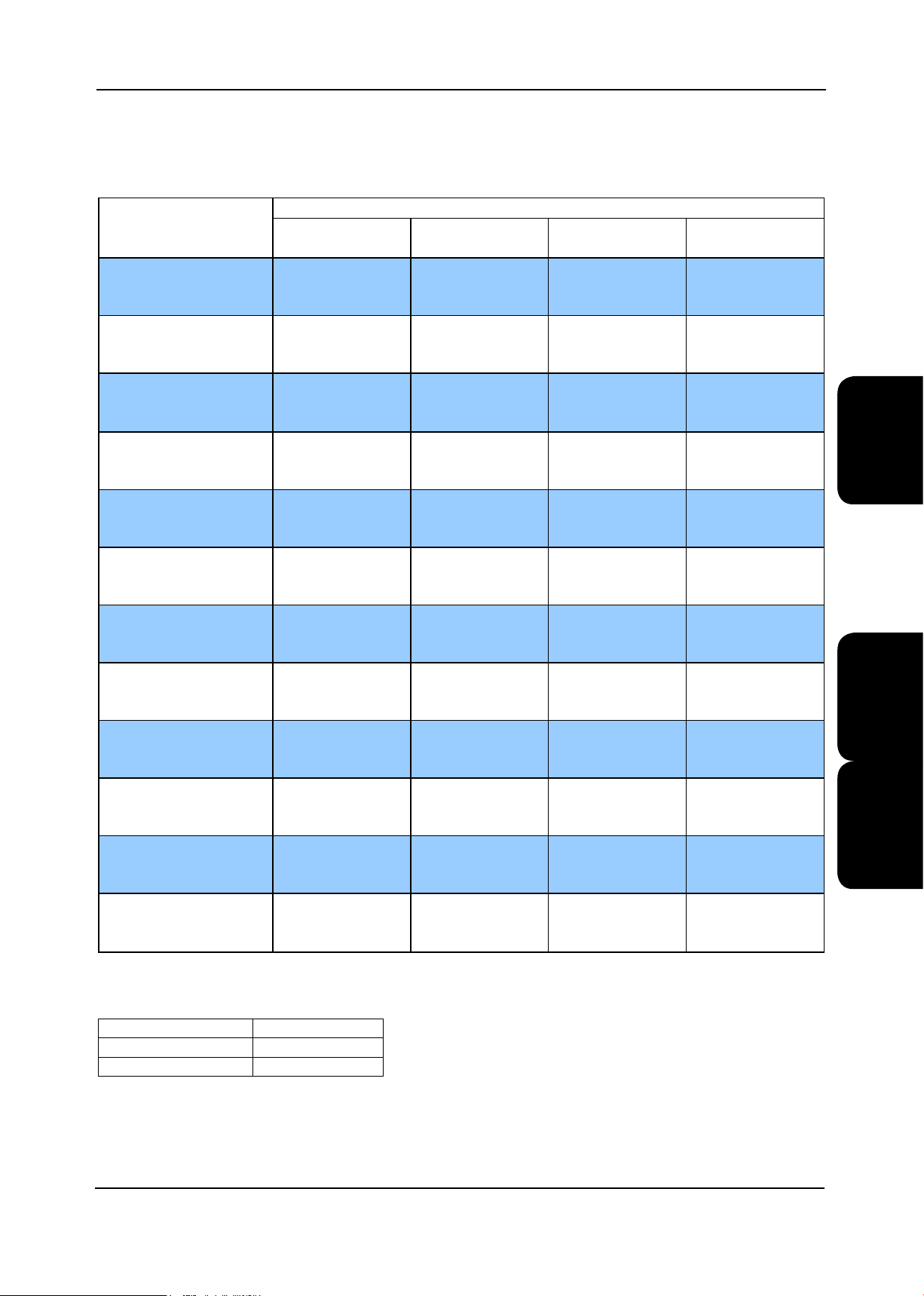
Technical Data Upow Units X Type
Performance Data Standard Condensers
EasiCool™Precision Air Conditioning
Cooling Capacity (1)
V28X-EZRE CR50
V28X2-EZRE CR50
V31X-EZRE CR50
V31X2-EZRE CR50
V35X-EZRE CR50
V35X2-EZRE CR50
V40X-EZRE CR65
V40X2-EZRE CR65
V45X2-EZRE CR80
V50X2-EZRE CR80
V55X2-EZRE CR80
V60X2-EZRE CR80
Ambient
Air On 25°C 30°C 35°C 40°C
(DB°C/%RH) TC (kW) SC (kW) TC (kW) SC (kW) TC (kW) SC (kW) TC (kW) SC (kW)
22/50 25.3 24.9 25.3 24.9 25.3 24.9 24.1 23.9
24/45 26.5 26.5 26.5 26.5 26.5 26.5 25.2 25.2
26/40 27.9 27.9 27.9 27.9 27.8 27.8 26.6 26.1
22/50 25.2 24.8 25.2 24.8 25.2 24.8 23.9 23.7
24/45 26.4 26.4 26.4 26.4 26.3 26.3 25.0 25.0
26/40 27.7 27.7 27.7 27.7 27.6 27.6 26.4 25.8
22/50 28.7 28.7 28.7 28.7 28.5 28.5 27.1 27.1
24/45 30.1 30.1 30.1 30.1 29.8 29.8 28.4 28.4
26/40 31.7 31.5 31.7 31.5 31.3 30.8 30.1 28.5
22/50 28.4 28.4 28.4 28.4 28.2 28.2 26.8 26.8
24/45 29.8 29.8 29.8 29.8 29.5 29.5 28.2 28.2
26/40 31.4 31.0 31.4 31.0 31.1 30.4 29.9 28.2
22/50 33.3 33.1 33.3 33.1 32.7 32.5 31.0 31.0
24/45 35.0 35.0 35.0 35.0 34.2 34.2 32.7 32.7
26/40 37.0 36.0 37.0 36.0 36.1 34.3 35.0 31.3
22/50 32.9 32.8 32.9 32.8 32.1 32.1 30.3 30.3
24/45 34.2 34.2 34.2 34.2 33.2 33.2 31.4 31.1
26/40 34.0 34.0 34.0 34.0 33.1 33.1 31.4 31.4
22/50 37.2 37.2 37.2 37.2 37.0 37.0 35.2 35.2
24/45 39.0 39.0 39.0 39.0 38.7 38.7 37.0 37.0
26/40 41.2 40.4 41.2 40.4 40.8 39.5 39.5 36.4
22/50 37.9 37.9 37.9 37.9 37.6 37.6 35.8 35.8
24/45 39.7 39.7 39.7 39.7 39.3 39.3 37.6 37.6
26/40 41.9 41.6 41.9 41.6 41.4 40.8 40.0 37.9
22/50 41.2 39.7 41.2 39.7 41.2 39.7 39.3 38.3
24/45 43.0 43.0 43.0 43.0 43.0 43.0 41.0 41.0
26/40 45.0 45.0 45.0 45.0 44.9 44.9 42.9 42.9
22/50 48.9 46.3 48.9 46.3 48.4 45.9 45.8 44.1
24/45 50.9 50.4 50.9 50.4 50.3 49.9 47.7 47.7
26/40 53.0 53.0 53.0 53.0 52.2 52.2 49.7 49.7
22/50 55.2 50.2 55.2 50.2 54.0 49.4 51.1 47.6
24/45 57.4 55.1 57.4 55.1 56.0 54.2 53.1 52.1
26/40 59.5 59.5 59.5 59.5 57.9 57.9 55.0 55.0
22/50 62.4 55.9 62.4 55.9 60.1 54.5 56.8 52.5
24/45 64.7 61.3 64.7 61.3 62.2 59.6 58.9 57.4
26/40 67.1 66.9 67.1 66.9 64.3 64.3 61.0 61.0
Technic a l X-TypeV
Operating Limits
Indoor Air Temperature +18°C to +28°C
Indoor RH% +40% to +55%
Outdoor Temperature -20°C to +41°C
TC = Total Cooling
SC = Sensible Cooling
(1) All data quoted is gross
EasiCool Technical Manual 7525389 V1.1.0_02_2013
77

EasiCool™ Precision Air Conditioning
Technical Data Upow Units X Type
Performance Data Larger Condensers
Cooling Capacity (1)
Air On 25°C 30°C 35°C 40°C 45°C
(DB°C/%RH) TC (kW) SC (kW) TC (kW) SC (kW) TC (kW) SC (kW) TC (kW) SC (kW) TC (kW) SC (kW)
22/50 6.2 6.1 6.2 6.1 6.2 6.1 6.0 5.9 5.7 5.7
V6X-EZRE CR16
V8X-EZRE CR22
V10X-EZRE CR22
V13X-EZRE CR30
Technic a l
V15X-EZRE CR30
V17X-EZRE CR50
V20X2-EZRE CR50
V22X2-EZRE CR65
V26X2-EZRE CR65
V28X-EZRE CR65
X-Type V
V28X2-EZRE CR65
V31X-EZRE CR65
24/45 6.5 6.5 6.5 6.5 6.5 6.5 6.3 6.3 6.0 6.0
26/40 6.8 6.8 6.8 6.8 6.8 6.8 6.5 6.5 6.3 6.3
22/50 7.9 7.9 7.9 7.9 7.9 7.9 7.6 7.6 7.3 7.3
24/45 8.2 8.2 8.2 8.2 8.2 8.2 8.0 8.0 7.6 7.6
26/40 8.6 8.6 8.6 8.6 8.6 8.6 8.4 8.4 8.1 8.1
22/50 10.3 10.3 10.3 10.3 10.3 10.3 9.9 9.9 9.4 9.4
24/45 10.8 10.8 10.8 10.8 10.8 10.8 10.3 10.3 9.8 9.8
26/40 11.2 11.2 11.2 11.2 11.2 11.2 10.8 10.8 10.4 10.4
22/50 13.4 12.4 13.4 12.4 13.4 12.4 12.8 12.0 12.2 11.6
24/45 13.9 13.7 13.9 13.7 13.9 13.7 13.3 13.3 12.6 12.6
26/40 14.4 14.4 14.4 14.4 14.4 14.4 13.7 13.7 13.1 13.1
22/50 15.2 14.5 15.2 14.5 15.2 14.5 14.4 14.0 13.7 13.5
24/45 15.8 15.7 15.8 15.7 15.7 15.7 15.0 15.0 14.3 14.3
26/40 16.2 16.2 16.2 16.2 16.2 16.2 15.6 15.6 14.8 14.8
22/50 17.5 16.6 17.5 16.6 17.5 16.6 17.0 16.3 16.2 15.7
24/45 18.1 18.1 18.1 18.1 18.1 18.1 17.5 17.5 16.7 16.7
26/40 18.6 18.6 18.6 18.6 18.6 18.6 18.0 18.0 17.2 17.2
22/50 21.0 19.9 21.0 19.9 21.0 19.9 20.2 19.4 19.2 18.7
24/45 21.8 21.8 21.8 21.8 21.8 21.8 21.0 21.0 20.0 20.0
26/40 22.7 22.7 22.7 22.7 22.7 22.7 21.8 21.8 20.9 20.9
22/50 21.6 21.3 21.6 21.3 21.6 21.3 21.1 20.9 20.1 20.1
24/45 22.5 22.5 22.5 22.5 22.5 22.5 22.0 22.0 21.1 21.1
26/40 23.5 23.5 23.5 23.5 23.5 23.5 23.0 23.0 22.0 22.0
22/50 26.5 24.2 26.5 24.2 26.5 24.2 25.6 23.6 24.3 22.8
24/45 27.5 26.5 27.5 26.5 27.5 26.5 26.5 25.8 25.3 24.9
26/40 28.6 28.6 28.6 28.6 28.6 28.6 27.5 27.5 26.3 26.3
22/50 25.3 24.9 25.3 24.9 25.3 24.9 24.5 24.2 23.4 23.3
24/45 26.5 26.5 26.5 26.5 26.5 26.5 25.7 25.7 24.6 24.6
26/40 27.9 27.9 27.9 27.9 27.9 27.9 27.1 26.8 26.1 25.2
22/50 25.2 24.8 25.2 24.8 25.2 24.8 24.4 24.1 23.2 23.1
24/45 26.4 26.4 26.4 26.4 26.4 26.4 25.5 25.5 24.4 24.4
26/40 27.7 27.7 27.7 27.7 27.7 27.7 26.9 26.5 25.9 24.8
22/50 28.7 28.7 28.7 28.7 28.7
24/45 30.1 30.1 30.1 30.1 30.1 30.1 29.0 29.0 27.8 27.8
26/40 31.7 31.5 31.7 31.5 31.7 31.5 30.6 29.6 29.5 27.4
Ambient
28.7 27.7 27.7 26.4 26.4
Operating Limits
Indoor Air Temperature +18°C to +28°C
Indoor RH% +40% to +55%
Outdoor Temperature -20°C to +41°C
TC = Total Cooling
SC = Sensible Cooling
(1) All data quoted is gross
78 EasiCool Technical Manual 7525389 V1.1.0_02_2013
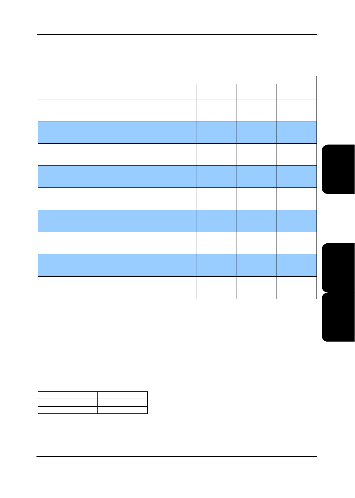
Technical Data Upow Units X Type
Performance Data Larger Condensers
EasiCool™Precision Air Conditioning
Cooling Capacity (1)
V31X2-EZRE CR65
V35X-EZRE CR65
V35X2-EZRE CR65
V40X-EZRE CR80
V40X2-EZRE CR80
V45X2-EZRE CR105
V50X2-EZRE CR105
V55X2-EZRE CR105
V60X2-EZRE CR105
Ambient
Air On 25°C 30°C 35°C 40°C 45°C
(DB°C/%RH) TC (kW) SC (kW) TC (kW) SC (kW) TC (kW) SC (kW) TC (kW) SC (kW) TC (kW) SC (kW)
22/50 28.4 28.4 28.4 28.4 28.4 28.4 27.4 27.4 26.2 26.2
24/45 29.8 29.8 29.8 29.8 29.8 29.8 28.8 28.8 27.6 27.6
26/40 31.4 31.0 31.4 31.0 31.4 31.0 30.4 29.2 29.4 27.1
22/50 33.3 33.1 33.3 33.1 33.3 33.1 31.8 31.8 30.3 30.3
24/45 35.0 35.0 35.0 35.0 35.0 35.0 33.4 33.4 32.0 31.9
26/40 37.0 36.0 37.0 36.0 36.8 35.8 35.6 32.9 34.7 30.0
22/50 32.9 32.8 32.9 32.8 32.9 32.8 31.1 31.1 29.5 29.4
24/45 34.2 34.2 34.2 34.2 34.2 34.2 32.3 32.2 30.7 30.0
26/40 34.0 34.0 34.0 34.0 34.0 34.0 32.2 32.2 30.8 30.8
22/50 37.2 37.2 37.2 37.2 37.2 37.2 35.7 35.7 34.1 34.1
24/45 39.0 39.0 39.0 39.0 39.0 39.0 37.5 37.5 36.0 35.6
26/40 41.2 40.4 41.2 40.4 41.2 40.4 39.9 37.5 38.9 34.5
22/50 37.9 37.9 37.9 37.9 37.9 37.9 36.4 36.4 34.8 34.8
24/45 39.7 39.7 39.7 39.7 39.7 39.7 38.2 38.2 36.7 36.6
26/40 41.9 41.6 41.9 41.6 41.9 41.6 40.5 39.0 39.4 36.2
22/50 41.2 39.7 41.2 39.7 41.2 39.7 39.8 38.7 38.0 37.3
24/45 43.0 43.0 43.0 43.0 43.0 43.0 41.5 41.5 39.7 39.7
26/40 45.0 45.0 45.0 45.0 45.0 45.0 43.5 43.5 41.8 41.8
22/50 48.9 46.3 48.9 46.3 48.9 46.3 46.7 44.7 44.3 43.0
24/45 50.9 50.4 50.9 50.4 50.9 50.4 48.6 48.6 46.2 46.2
26/40 53.0 53.0 53.0 53.0 53.0 53.0 50.6 50.6 48.2 48.2
22/50 55.2 50.2 55.2 50.2 55.1 50.1 52.2 48.3 49.4 46.5
24/45 57.4 55.1 57.4 55.1 57.1 54.9 54.2 52.9 51.4 50.9
26/40 59.5 59.5 59.5 59.5 59.1 59.1 56.2 56.2 53.3 53.3
22/50 62.4 55.9 62.4 55.9 61.5 55.4 58.3 53.4 55.0 51.3
24/45 64.7 61.3 64.7 61.3 63.7 60.6 60.4 58.4 57.0 56.0
26/40 67.1 66.9 67.1 66.9 65.8 65.8 62.5 62.5 59.1 59.1
Technic a l X-TypeV
Operating Limits
Indoor Air Temperature +18°C to +28°C
Indoor RH% +40% to +55%
Outdoor Temperature -20°C to +41°C
TC = Total Cooling
SC = Sensible Cooling
(1) All data quoted is gross
EasiCool Technical Manual 7525389 V1.1.0_02_2013
79

EasiCool™ Precision Air Conditioning
Technical Data Upow Units X Type
Noise Data
Sound Frequency (Hz) dB
Measurement
Discharge Air Power 72 66 70 68 68 68 67 59 55
V6X
V8X
V10X
Technic a l
V13X
V15X
V17X
V20X2
V22X2
X-Type V
V26X2
V28X
V28X2
Return Air Power 58 63 67 58 53 54 48 41 36
Case Breakout Power 58 63 67 58 53 54 48 41 36
Sound @ 3m Pressure 43 48 51 43 38 40 33 27 21
Discharge Air Power 78 71 75 74 73 73 72 65 60
Return Air Power 63 68 71 63 58 59 53 48 41
Case Breakout Power 63 68 71 63 58 59 53 48 41
Sound @ 3m Pressure 49 53 57 49 43 44 39 33 26
Discharge Air Power 81 74 78 77 76 76 75 68 63
Return Air Power 66 71 74 66 61 62 56 50 43
Case Breakout Power 66 71 74 66 61 62 56 50 43
Sound @ 3m Pressure 51 56 61 52 46 47 41 36 29
Discharge Air Power 78 72 75 73 73 73 72 65 60
Return Air Power 63 69 71 63 58 59 53 48 42
Case Breakout Power 63 69 71 63 58 59 53 48 42
Sound @ 3m Pressure 48 54 57 48 43 44 38 34 27
Discharge Air Power 74 71 76 73 70 69 68 63 58
Return Air Power 62 68 72 63 56 56 49 48 42
Case Breakout Power 62 68 72 63 56 56 49 48 42
Sound @ 3m Pressure 47 53 57 48 41 42 35 34 27
Discharge Air Power 78 75 79 77 74 73 71 67 62
Return Air Power 65 72 75 67 59 59 53 51 44
Case Breakout Power 65 72 75 67 59 59 53 51 44
Sound @ 3m Pressure 50 57 61 52 44 44 38 36 30
Discharge Air Power 82 75 79 78 77 78 76 69 64
Return Air Power 67 73 75 67 62 63 57 52 46
Case Breakout Power 67 73 75 67 62 63 57 52 46
Sound @ 3m Pressure 53 58 61 53 48 48 42 37 31
Discharge Air Power 86 80 84 82 81 82 80 73 68
Return Air Power 71 77 80 71 66 67 61 55 49
Case Breakout Power 71 77 80 71 66 67 61 55 49
Sound @ 3m Pressure 57 62 65 57 52 52 46 41 35
Discharge Air Power 86 80 84 82 81 82 80 73 68
Return Air Power 71 77 80 71 66 67 61 55 49
Case Breakout Power 71 77
Sound @ 3m Pressure 57 62 65 57 52 52 46 41 35
Discharge Air Power 90 102 95 86 84 85 81 81 78
Return Air Power 79 89 80 79 76 75 68 63 57
Case Breakout Power 79 89 80 79 76 75 68 63 57
Sound @ 3m Pressure 64 75 65 65 62 60 53 49 42
Discharge Air Power 90 102 95 86 84 85 81 81 78
Return Air Power 79 87 80 79 76 74 67 63 57
Case Breakout Power 79 87 80 79 76 74 67 63 57
Sound @ 3m Pressure 64 73 65 65 61 60 53 49 42
Overall
dB(A)
63 125 250 500 1000 2000 4000 8000
80 71 66 67 61 55 49
(1) dB(A) is the overall sound level, measured on the A scale
(2) All sound data measured at nominal conditions, Discharge Air, Return air and case breakout is sound power.
80 EasiCool Technical Manual 7525389 V1.1.0_02_2013

Technical Data Upow Units X Type
Noise Data
Sound Frequency (Hz) dB
Overall
dB(A)
V28X
V31X2
V35X
V35X2
V40X
V40X2
V45X2
V50X2
V55X2
V60X2
Measurement
Discharge Air Power 93 105 96 89 86 88 84 84 82
Return Air Power 81 92 80 82 78 77 70 66 60
Case Breakout Power 81 92 80 82 78 77 70 66 60
Sound @ 3m Pressure 66 77 66 67 64 62 56 51 45
Discharge Air Power 93 105 96 89 86 88 84 84 82
Return Air Power 81 91 80 82 77 77 70 66 60
Case Breakout Power 81 91 80 82 77 77 70 66 60
Sound @ 3m Pressure 66 76 66 67 63 62 55 51 46
Discharge Air Power 92 111 98 90 87 82 82 83 80
Return Air Power 81 97 82 84 80 72 69 66 58
Case Breakout Power 81 97 82 84 80 72 69 66 58
Sound @ 3m Pressure 67 82 68 69 66 58 54 51 44
Discharge Air Power 92 111 98 90 87 82 82 83 80
Return Air Power 81 97 82 84 79 72 69 66 59
Case Breakout Power 81 97 82 84 79 72 69 66 59
Sound @ 3m Pressure 66 82 68 69 65 58 54 51 45
Discharge Air Power 94 113 99 92 89 84 85 85 83
Return Air Power 83 98 84 85 82 74 71 68 61
Case Breakout Power 83 98 84 85 82 74 71 68 61
Sound @ 3m Pressure 68 84 69 71 67 59 56 53 46
Discharge Air Power 94 113 99 92 89 84 85 85 83
Return Air Power 82 98 84 85 81 74 71 68 62
Case Breakout Power 82 98 84 85 81 74 71 68 62
Sound @ 3m Pressure 68 85 69 71 66 59 56 53 47
Discharge Air Power 94 113 99 92 89 84 85 85 83
Return Air Power 83 98 84 85 83 74 71 68 62
Case Breakout Power 83 98 84 85 83 74 71 68 62
Sound @ 3m Pressure 69 84 69 71 68 59 57 53 47
Discharge Air Power 97 115 109 95 92 84 86 84 80
Return Air Power 84 99 93 86 83 74 71 66 58
Case Breakout Power 84 99 93 86 83 74 71 66 58
Sound @ 3m Pressure 70 85 79 72 68 60 57 52 43
Discharge Air Power 97 115 109 95 92 84 86 84 80
Return Air Power 84 99 93 86 83 74 72 66 58
Case Breakout Power 84 99
Sound @ 3m Pressure 70 85 79 72 68 60 57 52 43
Discharge Air Power 98 116 11 0 97 93 86 87 86 82
Return Air Power 86 102 94 89 85 76 73 69 60
Case Breakout Power 86 102 94 89 85 76 73 69 60
Sound @ 3m Pressure 72 87 80 75 70 61 59 54 46
EasiCool™Precision Air Conditioning
63 125 250 500 1000 2000 4000 8000
Technic a l X-TypeV
93 86 83 74 72 66 58
(1) dB(A) is the overall sound level, measured on the A scale
(2) All sound data measured at nominal conditions, Discharge Air, Return air and case breakout is sound power.
EasiCool Technical Manual 7525389 V1.1.0_02_2013
81

EasiCool™ Precision Air Conditioning
Technical Data Upow Units X Type
V6X - V10X
Mechanical Data
V6X-EZRE-0 V8X-EZRE-0 V10X-EZRE-0
Standard Condenser Match
Capacity
Nom Cooling (Gross)
Capacity Steps
Fan Power Input (Fan Gain)
Dimensions - W x D x H
Weight - Machine
Construction
Material/Colour
Evaporator
Cooling/Dehum Stages
Evaporator Fan Motor - EC Motor
Fan Transmission Type
Quantity
Motor Shaft Power
Maximum ESP
Technic a l
X-Type V
Nominal Airow
Compressor - Scroll
Quantity
Oil Charge Volume (Total)
Oil Type
Refrigeration
Refrigeration Control & Type
Holding Charge
Connections
Liquid (Sweat)
Discharge (Sweat)
Condensate Drain Hose
Filtration
Quantity
OPTIONAL EXTRAS
Larger Condenser Match
Nom Cooling (Gross)
Hot Gas Reheat
Nom Heating (Gross)
Electric Heating (Total)
Humidier
Capacity
Feed/Drain
Condensate Pump
Head
Flow
Drain
Optional Fan - EC Motor
Fan Transmission Type
Quantity
Motor Shaft Power
Speed @ 25Pa / Maximum ESP
Maximum ESP
Fan Power Input (Fan Gain)
Low Pressure Hot Water
Capacity Gross
Water Flow (Nominal)
LPHW Connection Sizes
(1) kW 6.4 8.2 10.6
(2) kW 0.17 0.39 0.58
mm 670 x 670 x 1940 670 x 670 x 1940 670 x 670 x 1940
(3) kg 174 173 177
(4) kW N/A N/A N/A
Pa 564 507 295
m³/s 0.55 0.75 0.95
l 0.70 0.70 1.20
(5) Inert Gas
in 3/8 3/8 3/8
in 1/2 1/2 1/2
mm 19 19 19
(1) kW 6.5 8.2 10.8
(6) kW 4.2 4.9 5.5
kW 7.5 7.5 7.5
kg/hr 0.6 - 3.0 0.6 - 3.0 0.6 - 3.0
m 8 8 8
l/m 5 5 5
kW 1 1 1
(4) kW N/A N/A N/A
rpm 1340 / 2215 1705 / 2215 2140 / 2215
Pa 350 220 45
(2) kW 0.19 0.36 0.62
(7) kW 6.6 7.9 8.9
l/s 0.15 0.18 0.20
mm 22 22 22
1 x CR12 1 x CR16 1 x CR16
1 1 1
Panels: Galvanised Sheet Steel, Epoxy Baked Powder Paint - Black, (RAL7021)
Frame: Aluminium Frame with Aluminium Corners
Ried Copper Tube/Turbulated Hydrophilic Coated Aluminium Fins
1/1 1/1 1/1
Centrifugal Forward Curved EC - Designed to 25Pa ESP
Direct Drive
1 1 1
Single
1 1 1
Polyol Ester
Single Circuit
Thermostatic Expansion Valve (Optional EEV) / R410A
Disposable to BS EN 779 - G4 - 50mm
1 1 1
CR16 CR22 CR22
3/4” BSPF Braided Flexible Hose / 19mm Hose Connection
10mm Stainless Steel Stub Connection
Centrifugal Backward Curved EC - Designed to 25Pa ESP
Direct Drive
Copper Tube/Aluminium Fin
82 EasiCool Technical Manual 7525389 V1.1.0_02_2013

EasiCool™Precision Air Conditioning
Technical Data Upow Units X Type
Electrical Data
Standard Condenser Match
Max Mains Incoming Cable Size
Mains Supply
Control Circuit
Unit Data Full Function - X
Nominal Run Amps
Maximum Start Amps
Recommended Mains Fuse Size
Unit Data Cooling Only - X
Nominal Run Amps
Maximum Start Amps
Recommended Mains Fuse Size
Evaporator Fan - EC Motor Per Fan
Quantity
Maximum Electrical Input Power
Full Load Amps
Locked Rotor Amps
Compressor - Per Compressor
Quantity x Motor Size
Nominal Run Amps
Locked Rotor Amps
Type of Start
Standard Condenser Match - AC Motor - Per Fan
Quantity
Maximum Electrical Input Power
Full Load Amps
OPTIONAL EXTRAS
Electric Heating
Stage of Reheat
Number of Elements
Rating
Current per Phase
Humidier
Capacity
Rating
Full Load Amps
Evaporator Fan Options
Larger Fan Motor - AC Motor - Per Fan
Quantity
Maximum Electrical Input Power
Full Load Amps
Locked Rotor Amps
Standard Size Motor - EC Motor - Per Fan
Quantity
Quantity x Motor Size
Full Load Amps
Condenser Fan Options
Standard Condenser Motor - EC Motor - Per Fan
Quantity
Maximum Electrical Input Power
Full Load Amps
mm² 6 6 6
V 400V / 3PH + N / 50HZ
VAC 24 24 24
(1)
A 20.0 21.0 21.2
A 42.4 51.4 58.6
A 25 25 25
(2) A 9.2 10.2 10.4
A 31.6 40.6 47.8
A 16 16 16
(3) kW 1.3 1.3 1.15
A 5.6 5.6 4.8
A 5.6 5.6 4.8
kW 1 x 2 1 x 2.6 1 x 3.3
A 3.6 4.6 5.6
A 26 35 43
kW 0.27 0.27 0.27
A 1.1 1.1 1.1
kW 7.5 7.5 7.5
A 10.83 10.83 10.83
kg/hr 3 3 3
kW 2.25 2.25 2.25
A 3.25 3.25 3.25
(3) kW N/A N/A N/A
A N/A N/A N/A
A N/A N/A N/A
(3) kW 0.94 0.94 0.94
A 1.5 1.5 1.5
(3) kW 0.7 0.7 0.7
A 3.1 3.1 3.1
V6X - V10X
V6X-EZRE-0 V8X-EZRE-0 V10X-EZRE-0
1 x CR12 1 x CR16 1 x CR16
Centrifugal Forward Curved DD EC - Designed to 25Pa ESP
1 1 1
Direct On Line
1 1 1
1 1 1
3 3 3
Centrifugal Backward Curved DD EC - Designed to 25Pa ESP
1 1 1
1 1 1
Technic a l X-TypeV
Mechanical
(1) Entering air 24°C/45% RH ambient 35°C.
(2)
Fan Gain / Fan power input based upon fan operating with design airow at 25Pa ESP, these values may change with different ESP.
(3) With Standard forward curved fan motors; Machine weight includes a refrigerant charge.
(4) Backward curved EC fan options quote electrical power. All other options quote shaft power.
(5) For refrigerant charges, refer to Unit Refrigerant Charge (kg/Circuit).
(6) Based on air temperature of 15.5°C leaving the evaporator coil.
(7) Based upon low pressure hot water 82°C inlet / 71°C outlet. Air on 20°C. Refer to Low Pressure Hot Water.
Electrical
(1) Values given for full function units (incl. electric heating, humidication and matched condenser) at 7°C evaporating and 54.4°C condensing with standard
forward curved fan motors, for optional data, please contact Airedale.
(2) Values given for Cooling only units (incl. Compressor, evaporator fan and matched condenser) at 7°C evaporating and 54.4°C condensing, for optional
data, please contact Airedale.
(3) Electrical input power relates to the maximum absorbed electrical power. Actual operating fan power input is shown in the mechanical data tables.
EasiCool Technical Manual 7525389 V1.1.0_02_2013
83

EasiCool™ Precision Air Conditioning
Technical Data Upow Units X Type
V13X - V17X
Mechanical Data
V13X-EZRE-0 V15X-EZRE-0 V17X-EZRE-0
Standard Condenser Match
Capacity
Nom Cooling (Gross)
Capacity Steps
Fan Power Input (Fan Gain)
Dimensions - W x D x H
Weight - Machine
Construction
Material/Colour
Evaporator
Cooling/Dehum Stages
Evaporator Fan Motor - EC Motor
Fan Transmission Type
Quantity
Motor Shaft Power
Maximum ESP
Technic a l
X-Type V
Nominal Airow
Compressor - Scroll
Quantity
Oil Charge Volume (Total)
Oil Type
Refrigeration
Refrigeration Control & Type
Holding Charge - X
Connections
Liquid (Sweat) - X
Discharge (Sweat) - X
Condensate Drain Hose
Filtration
Quantity
OPTIONAL EXTRAS
Larger Condenser Match
Nom Cooling (Gross)
Hot Gas Reheat
Nom Heating (Gross)
Electric Heating (Total)
Humidier
Capacity
Feed/Drain
Condensate Pump
Head
Flow
Drain
Optional Fan - EC Motor
Fan Transmission Type
Quantity
Motor Shaft Power
Speed @ 25Pa / Maximum ESP
Maximum ESP
Fan Power Input (Fan Gain)
Low Pressure Hot Water
Capacity Gross
Water Flow (Nominal)
LPHW Connection Sizes
(1) kW 13.7 15.4 17.8
(2) kW 0.50 0.65 0.98
mm 990 x 670 x 1940 990 x 670 x 1940 990 x 670 x 1940
(3) kg 211 235 236
(4) kW N/A N/A N/A
Pa 315 415 198
m³/s 1.00 1.20 1.40
l 1.20 1.66 1.89
(5) Inert Gas
in 3/8 3/8 3/8
in 5/8 5/8 5/8
mm 19 19 19
(1) kW 13.9 15.7 18.1
(6) kW 6.8 7.7 8.2
kW 7.5 7.5 7.5
kg/hr 0.6 - 3.0 0.6 - 3.0 0.6 - 3.0
m 8 8 8
l/m 5 5 5
(4) kW N/A N/A N/A
rpm 1125 / 1560 1330 / 1560 1560 / 1560
Pa 275 165 25
(2) kW 0.36 0.54 0.79
(7) kW 11.5 12.7 13.7
l/s 0.26 0.28 0.31
mm 22 22 22
1 x CR22 1 x CR22 1 x CR30
1 1 1
Panels: Galvanised Sheet Steel, Epoxy Baked Powder Paint - Black, (RAL7021)
Frame: Aluminium Frame with Aluminium Corners
Ried Copper Tube/Turbulated Hydrophilic Coated Aluminium Fins
1/1 1/1 1/1
Centrifugal Forward Curved EC - Designed to 25Pa ESP
Direct Drive
1 1 1
Single
1 1 1
Polyol Ester
Single Circuit
Thermostatic Expansion Valve (Optional EEV) / R410A
Disposable to BS EN 779 - G4 - 50mm
2 2 2
CR30 CR30 CR50
3/4” BSPF Braided Flexible Hose / 19mm Hose Connection
10mm Stainless Steel Stub Connection
Centrifugal Backward Curved EC - Designed to 25Pa ESP
Direct Drive
1 1 1
Copper Tube/Aluminium Fin
84 EasiCool Technical Manual 7525389 V1.1.0_02_2013

EasiCool™Precision Air Conditioning
Technical Data Upow Units X Type
Electrical Data
Standard Condenser Match
Max Mains Incoming Cable Size
Mains Supply
Control Circuit
Unit Data Full Function - X
Nominal Run Amps
Maximum Start Amps
Recommended Mains Fuse Size
Unit Data Cooling Only - X
Nominal Run Amps
Maximum Start Amps
Recommended Mains Fuse Size
Evaporator Fan - EC Motor Per Fan
Quantity
Maximum Electrical Input Power
Full Load Amps
Locked Rotor Amps
Compressor - Per Compressor
Quantity x Motor Size
Nominal Run Amps
Locked Rotor Amps
Type of Start
Standard Condenser Match - AC Motor - Per Fan
Quantity
Maximum Electrical Input Power
Full Load Amps
OPTIONAL EXTRAS
Electric Heating
Stage of Reheat
Number of Elements
Rating
Current per Phase
Humidier
Capacity
Rating
Full Load Amps
Evaporator Fan Options
Larger Fan Motor - AC Motor - Per Fan
Quantity
Maximum Electrical Input Power
Full Load Amps
Locked Rotor Amps
Standard Size Motor - EC Motor - Per Fan
Quantity
Quantity x Motor Size
Full Load Amps
Condenser Fan Options
Standard Condenser Motor - EC Motor - Per Fan
Quantity
Maximum Electrical Input Power
Full Load Amps
mm² 6 6 6
V 400V / 3PH + N / 50HZ
VAC 24 24 24
(1)
A 22.7 26.6 27.6
A 79.6 82.2 92.2
A 32 32 32
(2) A 11.9 15.8 16.8
A 68.8 71.4 81.4
A 16 20 20
(3) kW 1.15 1.75 1.75
A 4.8 7.4 7.4
A 4.8 7.4 7.4
kW 1 x 4.2 1 x 4.8 1 x 5.6
A 7.1 8.4 9.4
A 64 64 74
kW 0.6 0.6 0.6
A 2.62 2.62 2.62
kW 7.5 7.5 7.5
A 10.83 10.83 10.83
kg/hr 3 3 3
kW 2.25 2.25 2.25
A 3.25 3.25 3.25
(3) kW N/A N/A N/A
A N/A N/A N/A
A N/A N/A N/A
(3) kW 1 1 1
A 1.85 1.85 1.85
(3) kW 0.73 0.73 0.73
A 3.3 3.3 3.3
V13X - V17X
V13X-EZRE-0 V15X-EZRE-0 V17X-EZRE-0
1 x CR22 1 x CR22 1 x CR30
Centrifugal Forward Curved DD EC - Designed to 25Pa ESP
1 1 1
Direct On Line
1 1 1
1 1 1
3 3 3
Centrifugal Backward Curved DD EC - Designed to 25Pa ESP
1 1 1
1 1 1
Technic a l X-TypeV
Mechanical
(1) Entering air 24°C/45% RH ambient 35°C.
(2)
Fan Gain / Fan power input based upon fan operating with design airow at 25Pa ESP, these values may change with different ESP.
With Standard forward curved fan motors; Machine weight includes a refrigerant charge.
(3)
(4) Backward curved EC fan options quote electrical power. All other options quote shaft power.
(5) For refrigerant charges, refer to Unit Refrigerant Charge (kg/Circuit).
(6)
Based on air temperature of 15.5°C leaving the evaporator coil.
Based upon low pressure hot water 82°C inlet / 71°C outlet. Air on 20°C. Refer to Low Pressure Hot Water.
(7)
Electrical
(1) Values given for full function units (incl. electric heating, humidication and matched condenser) at 7°C evaporating and 54.4°C condensing with standard
forward curved fan motors, for optional data, please contact Airedale.
(2) Values given for Cooling only units (incl. Compressor, evaporator fan and matched condenser) at 7°C evaporating and 54.4°C condensing, for optional
data, please contact Airedale.
(3) Electrical input power relates to the maximum absorbed electrical power. Actual operating fan power input is shown in the mechanical data tables.
EasiCool Technical Manual 7525389 V1.1.0_02_2013
85

EasiCool™ Precision Air Conditioning
V20X2 - V26X2Technical Data Upow Units X Type
Mechanical Data
V20X2-EZRE-0 V22X2-EZRE-0 V26X2-EZRE-0
Standard Condenser Match
Capacity
Nom Cooling (Gross)
Capacity Steps
Fan Power Input (Fan Gain)
Dimensions - W x D x H
Weight - Machine
Construction
Material/Colour
Evaporator
Cooling/Dehum Stages
Evaporator Fan Motor - EC Motor
Fan Transmission Type
Quantity
Motor Shaft Power
Maximum ESP
Technic a l
X-Type V
Nominal Airow
Compressor - Scroll
Quantity
Oil Charge Volume (Total)
Oil Type
Refrigeration
Refrigeration Control & Type
Holding Charge
Connections
Liquid (Sweat)
Discharge (Sweat)
Condensate Drain Hose
Filtration
Quantity
OPTIONAL EXTRAS
Larger Condenser Match
Nom Cooling (Gross)
Hot Gas Reheat
Nom Heating (Gross)
Electric Heating (Total)
Humidier
Capacity
Feed/Drain
Condensate Pump
Head
Flow
Drain
Optional Fan - EC Motor
Fan Transmission Type
Quantity
Motor Shaft Power
Speed @ 25Pa / Maximum ESP
Maximum ESP
Fan Power Input (Fan Gain)
Low Pressure Hot Water
Capacity Gross
Water Flow (Nominal)
LPHW Connection Sizes
(1) kW 21.1 22.5 27.4
(2) kW 1.08 1.70 1.70
mm 1310 x 670 x 1940 1310 x 670 x 1940 1310 x 670 x 1940
(3) kg 289 289 289
(4) kW N/A N/A N/A
Pa 335 185 70
m³/s 1.70 2.00 2.00
l 2.40 2.40 2.40
(5) Inert Gas
in 1/2 1/2 1/2
in 7/8 7/8 7/8
mm 19 19 19
(1) kW 21.8 22.5 27.5
(6) kW 11.8 12.7 12.7
kW 15.0 15.0 15.0
kg/hr 0.6 - 3.0 0.6 - 3.0 0.6 - 3.0
m 8 8 8
l/m 5 5 5
(4) kW N/A N/A N/A
rpm 1830 / 2165 2165 / 2165 2165 / 2165
Pa 285 25 25
(2) kW 0.51 0.79 0.79
(7) kW 19.2 19.9 19.9
l/s 0.43 0.44 0.44
mm 22 22 22
1 x CR30 1 x CR50 1 x CR50
2 2 2
Panels: Galvanised Sheet Steel, Epoxy Baked Powder Paint - Black, (RAL7021)
Frame: Aluminium Frame with Aluminium Corners
Ried Copper Tube/Turbulated Hydrophilic Coated Aluminium Fins
2/1 2/1 2/1
Centrifugal Forward Curved EC - Designed to 25Pa ESP
Direct Drive
2 2 2
Tandem
2 2 2
Polyol Ester
Single Circuit
Thermostatic Expansion Valve (Optional EEV) / R410A
Disposable to BS EN 779 - G4 - 50mm
3 3 3
CR50 CR65 CR65
3/4” BSPF Braided Flexible Hose / 19mm Hose Connection
10mm Stainless Steel Stub Connection
Centrifugal Backward Curved EC - Designed to 25Pa ESP
Direct Drive
1 1 1
Copper Tube/Aluminium Fin
86 EasiCool Technical Manual 7525389 V1.1.0_02_2013

EasiCool™Precision Air Conditioning
Technical Data Upow Units X Type
Electrical Data
Standard Condenser Match
Max Mains Incoming Cable Size
Mains Supply
Control Circuit
Unit Data Full Function - X
Nominal Run Amps
Maximum Start Amps
Recommended Mains Fuse Size
Unit Data Cooling Only - X
Nominal Run Amps
Maximum Start Amps
Recommended Mains Fuse Size
Evaporator Fan - EC Motor Per Fan
Quantity
Maximum Electrical Input Power
Full Load Amps
Locked Rotor Amps
Compressor - Per Compressor
Quantity x Motor Size
Nominal Run Amps
Locked Rotor Amps
Type of Start
Standard Condenser Match - AC Motor - Per Fan
Quantity
Maximum Electrical Input Power
Full Load Amps
OPTIONAL EXTRAS
Electric Heating
Stage of Reheat
Number of Elements
Rating
Current per Phase
Humidier
Capacity
Rating
Full Load Amps
Evaporator Fan Options
Larger Fan Motor - AC Motor - Per Fan
Quantity
Maximum Electrical Input Power
Full Load Amps
Locked Rotor Amps
Standard Size Motor - EC Motor - Per Fan
Quantity
Quantity x Motor Size
Full Load Amps
Condenser Fan Options
Standard Condenser Motor - EC Motor - Per Fan
Quantity
Maximum Electrical Input Power
Full Load Amps
mm² 35 35 35
V 400V / 3PH + N / 50HZ
VAC 24 24 24
(1)
A 37.7 38.1 41.1
A 75.1 75.5 98.0
A 50 50 50
(2) A 16.0 16.4 19.4
A 53.4 53.8 76.3
A 20 20 25
(3) kW 1.15 1.15 1.15
A 4.8 4.8 4.8
A 4.8 4.8 4.8
kW 2 x 3.3 2 x 3.3 2 x 4.2
A 5.6 5.6 7.1
A 43 43 64
kW 0.6 0.6 0.6
A 2.62 2.62 2.62
kW 15 15 15
A 21.65 21.65 21.65
kg/hr 3 3 3
kW 2.25 2.25 2.25
A 3.25 3.25 3.25
(3) kW N/A N/A N/A
A N/A N/A N/A
A N/A N/A N/A
(3) kW 2.55 2.55 2.55
A 3.9 3.9 3.9
(3) kW 0.73 0.73 0.73
A 3.3 3.3 3.3
V20X2 - V26X2
V20X2-EZRE-0 V22X2-EZRE-0 V26X2-EZRE-0
1 x CR30 1 x CR50 1 x CR50
Centrifugal Forward Curved DD EC - Designed to 25Pa ESP
2 2 2
Direct On Line
2 2 2
2 2 2
6 6 6
Centrifugal Backward Curved DD EC - Designed to 25Pa ESP
1 1 1
1 2 2
Technic a l X-TypeV
Mechanical
(1) Entering air 24°C/45% RH ambient 35°C.
(2)
Fan Gain / Fan power input based upon fan operating with design airow at 25Pa ESP, these values may change with different ESP.
With Standard forward curved fan motors; Machine weight includes a refrigerant charge.
(3)
(4) Backward curved EC fan options quote electrical power. All other options quote shaft power.
(5) For refrigerant charges, refer to Unit Refrigerant Charge (kg/Circuit).
(6)
Based on air temperature of 15.5°C leaving the evaporator coil.
Based upon low pressure hot water 82°C inlet / 71°C outlet. Air on 20°C. Refer to Low Pressure Hot Water.
(7)
Electrical
(1) Values given for full function units (incl. electric heating, humidication and matched condenser) at 7°C evaporating and 54.4°C condensing with standard
forward curved fan motors, for optional data, please contact Airedale.
(2) Values given for Cooling only units (incl. Compressor, evaporator fan and matched condenser) at 7°C evaporating and 54.4°C condensing, for optional
data, please contact Airedale.
(3) Electrical input power relates to the maximum absorbed electrical power. Actual operating fan power input is shown in the mechanical data tables.
EasiCool Technical Manual 7525389 V1.1.0_02_2013
87

EasiCool™ Precision Air Conditioning
V28X- V31X2Technical Data Upow Units X Type
Mechanical Data
V28X-EZRE-0 V28X2-EZRE-0 V31X-EZRE-0 V31X2-EZRE-0
Standard Condenser Match
Capacity
Nom Cooling (Gross)
Capacity Steps
Fan Power Input (Fan Gain)
Dimensions - W x D x H
Weight - Machine
Construction
Material/Colour
Evaporator
Cooling/Dehum Stages
Evaporator Fan Motor - AC Motor
Fan Transmission Type
Quantity
Motor Shaft Power
Speed @ 25Pa / Maximum ESP
Technic a l
X-Type V
Maximum ESP
Nominal Airow
Compressor - Scroll
Quantity
Oil Charge Volume (Total)
Oil Type
Refrigeration
Refrigeration Control & Type
Holding Charge
Connections
Liquid (Sweat)
Discharge (Sweat)
Condensate Drain Hose
Filtration
Quantity
OPTIONAL EXTRAS
Larger Condenser Match
Nom Cooling (Gross)
Hot Gas Reheat
Nom Heating (Gross)
Electric Heating (Total)
Humidier
Capacity
Feed/Drain
Condensate Pump
Head
Flow
Drain
Evaporator Fan Options:
Larger Fan Motor - AC Motor
Fan Transmission Type
Quantity
Motor Shaft Power
Speed @ Maximum ESP
Maximum ESP
Fan Power Input (Fan Gain)
Optional Fan - EC Motor
Fan Transmission Type
Quantity
Motor Shaft Power
Speed @ 25Pa / Maximum ESP
Maximum ESP
Fan Power Input (Fan Gain)
Low Pressure Hot Water
Capacity Gross
Water Flow (Nominal)
LPHW Connection Sizes
(1) kW 26.5 26.3 29.8 29.5
(2) kW 3.50 3.50 4.60 4.60
mm 1460 x 750 x 1940 1460 x 750 x 1940 1460 x 750 x 1940 1460 x 750 x 1940
(3) kg 412 421 412 445
(4) kW 3.0 3.0 4.0 4.0
rpm 1420 / 1552 1420 / 1552 1600 / 1612 1600 / 1612
Pa 160 160 35 35
m³/s 2.40 2.40 2.80 2.80
l 3.30 2.48 3.30 3.32
(5) Inert Gas
in 1/2 1/2 1/2 1/2
in 7/8 7/8 7/8 7/8
mm 19 19 19 19
(1) kW 26.5 26.4 30.1 29.8
(6) kW 12.8 12.8 13.7 13.7
kW 22.5 22.5 22.5 22.5
kg/hr 1.6 - 8.0 1.6 - 8.0 1.6 - 8.0 1.6 - 8.0
m 10.8 10.8 10.8 10.8
l/m 5 5 5 5
(4) kW 4.0 4.0 N/A N/A
rpm 1910 1910 N/A N/A
Pa 470 470 N/A N/A
(2) kW 4.60 4.60 N/A N/A
(4) kW N/A N/A N/A N/A
rpm 1700 / 2165 1700 / 2165 1935 / 2165 1935 / 2165
Pa 440 440 225 225
(2) kW 2.02 2.02 3.02 3.02
(7) kW 21.7 21.7 23.2 23.2
l/s 0.48 0.48 0.52 0.52
mm 22 22 22 22
1 x CR50 1 x CR50 1 x CR50 1 x CR50
1 2 1 2
Panels: Galvanised Sheet Steel, Epoxy Baked Powder Paint - Black, (RAL7021)
Frame: Aluminium Frame with Aluminium Corners
Ried Copper Tube/Turbulated Hydrophilic Coated Aluminium Fins
1/1 2/1 1/1 2/1
Centrifugal Forward Curved AC - Designed to 25Pa ESP
Belt and Pulley
1 1 1 1
Single Tandem Single Tandem
1 2 1 2
Polyol Ester
Single Circuit
Thermostatic Expansion Valve (Optional EEV) / R410A
Disposable to BS EN 779 - G4 - 75mm
3 3 3 3
CR65 CR65 CR65 CR65
3/4” BSPF Braided Flexible Hose / 19mm Hose Connection
10mm Stainless Steel Stub Connection
Centrifugal Forward Curved AC - Designed to 25Pa ESP
Belt & Pulley
1 1 N/A N/A
Centrifugal Backward Curved EC - Designed to 25Pa ESP
Direct Drive
2 2 2 2
Copper Tube/Aluminium Fin
88 EasiCool Technical Manual 7525389 V1.1.0_02_2013

Electrical Data
Standard Condenser Match
Max Mains Incoming Cable Size
Mains Supply
Control Circuit
Unit Data Full Function - X
Nominal Run Amps
Maximum Start Amps
Recommended Mains Fuse Size
Unit Data Cooling Only - X
Nominal Run Amps
Maximum Start Amps
Recommended Mains Fuse Size
Evaporator Fan - AC Motor Per Fan
Quantity
Maximum Electrical Input Power
Full Load Amps
Locked Rotor Amps
Compressor - Per Compressor
Quantity x Motor Size
Nominal Run Amps
Locked Rotor Amps
Type of Start
Standard Condenser Match - AC Motor - Per Fan
Quantity
Maximum Electrical Input Power
Full Load Amps
OPTIONAL EXTRAS
Electric Heating
Stage of Reheat
Number of Elements
Rating
Current per Phase
Humidier
Capacity
Rating
Full Load Amps
Evaporator Fan Options
Larger Fan Motor - AC Motor - Per Fan
Quantity
Maximum Electrical Input Power
Full Load Amps
Locked Rotor Amps
Standard Size Motor - EC Motor - Per Fan
Quantity
Quantity x Motor Size
Full Load Amps
Condenser Fan Options
Standard Condenser Motor - EC Motor - Per Fan
Quantity
Maximum Electrical Input Power
Full Load Amps
EasiCool™Precision Air Conditioning
V28X- V31X2Technical Data Upow Units X Type
V28X-EZRE-0 V28X2-EZRE-0 V31X-EZRE-0 V31X2-EZRE-0
1 x CR50 1 x CR50 1 x CR50 1 x CR50
mm² 35 35 35 35
V 400V / 3PH + N / 50HZ
VAC 24 24 24 24
(1)
A 59.4 58.6 63.2 63.1
A 200.4 115.5 176.3 118.7
A 80 80 80 80
(2) A 26.9 26.1 30.8 30.66
A 167.9 83.0 143.9 86.26
A 32 32 40 40
Centrifugal Forward Curved Belt & Pulley AC - Designed to 25Pa ESP
1 1 1 1
(3) kW 3.5 3.5 4.6 4.6
A 6.18 6.18 8.12 8.12
A 43.3 43.3 60.9 60.9
kW 1 x 8.4 2 x 4.2 1 x 9.47 2 x 4.8
A 15 7.1 16.9 8.4
A 156 64 130 64
Direct On Line
2 2 2 2
kW 0.6 0.6 0.6 0.6
A 2.62 2.62 2.62 2.62
3 3 3 3
9 9 9 9
kW 22.5 22.5 22.5 22.5
A 32.48 32.48 32.48 32.48
kg/hr 8 8 8 8
kW 6.00 6.00 6.00 6
A 8.66 8.66 8.66 8.66
Centrifugal Forward Curved Belt & Pulley AC - Designed to 25Pa ESP
(3) kW 1 x 4.0 1 x 4.0 N/A N/A
A 8.12 8.12 N/A N/A
A 60.9 60.9 N/A N/A
Centrifugal Backward Curved DD EC - Designed to 25Pa ESP
2.00 2 2 2
(3) kW 2.55 2.55 2.55 2.55
A 3.9 3.9 3.9 3.9
2 2 2 2
(3) kW 0.73 0.73 0.73 0.73
A 3.3 3.3 3.3 3.3
Technic a l X-TypeV
Mechanical
(1) Entering air 24°C/45% RH ambient 35°C.
(2)
Fan Gain / Fan power input based upon fan operating with design airow at 25Pa ESP, these values may change with different ESP.
With Standard forward curved fan motors; Machine weight includes a refrigerant charge.
(3)
(4) Backward curved EC fan options quote electrical power. All other options quote shaft power.
(5) For refrigerant charges, refer to Unit Refrigerant Charge (kg/Circuit).
(6)
Based on air temperature of 15.5°C leaving the evaporator coil.
Based upon low pressure hot water 82°C inlet / 71°C outlet. Air on 20°C. Refer to Low Pressure Hot Water.
(7)
Electrical
(1) Values given for full function units (incl. electric heating, humidication and matched condenser) at 7°C evaporating and 54.4°C condensing with standard
forward curved fan motors, for optional data, please contact Airedale.
(2) Values given for Cooling only units (incl. Compressor, evaporator fan and matched condenser) at 7°C evaporating and 54.4°C condensing, for optional
data, please contact Airedale.
(3) Electrical input power relates to the maximum absorbed electrical power. Actual operating fan power input is shown in the mechanical data tables.
EasiCool Technical Manual 7525389 V1.1.0_02_2013
89

EasiCool™ Precision Air Conditioning
V35X - V45X2Technical Data Upow Units X Type
Mechanical Data
V35X-EZRE-0 V35X2-EZRE-0 V40X-EZRE-0 V40X2-EZRE-0 V45X2-EZRE-0
Standard Condenser Match
Capacity
Nom Cooling (Gross)
Capacity Steps
Fan Power Input (Fan Gain)
Dimensions - W x D x H
Weight - Machine
Construction
Material/Colour
Evaporator
Cooling/Dehum Stages
Evaporator Fan Motor - AC Motor
Fan Transmission Type
Quantity
Motor Shaft Power
Speed @ 25Pa / Maximum ESP
Technic a l
X-Type V
Maximum ESP
Nominal Airow
Compressor - Scroll
Quantity
Oil Charge Volume (Total)
Oil Type
Refrigeration
Refrigeration Control & Type
Holding Charge
Connections
Liquid (Sweat)
Discharge (Sweat)
Condensate Drain Hose
Filtration
Quantity
OPTIONAL EXTRAS
Larger Condenser Match
Nom Cooling (Gross)
Hot Gas Reheat
Nom Heating (Gross)
Electric Heating (Total)
Humidier
Capacity
Feed/Drain
Condensate Pump
Head
Flow
Drain
Evaporator Fan Options:
Larger Fan Motor - AC Motor
Fan Transmission Type
Quantity
Motor Shaft Power
Speed @ Maximum ESP
Maximum ESP
Fan Power Input (Fan Gain)
Optional Fan - EC Motor
Fan Transmission Type
Quantity
Motor Shaft Power
Speed @ 25Pa / Maximum ESP
Maximum ESP
Fan Power Input (Fan Gain)
Low Pressure Hot Water
Capacity Gross
Water Flow (Nominal)
LPHW Connection Sizes
(1) kW 34.2 33.2 38.7 39.3 43.0
(2) kW 4.60 4.60 6.30 6.30 6.30
mm 1835 x 750 x 1940 1835 x 750 x 1940 1835 x 750 x 1940 1835 x 750 x 1940 1835 x 750 x 1940
(3) kg 474 516 497 525 531
(4) kW 4.00 4.00 4.00 4.00 5.50
rpm 1440 / 1468 1440 / 1468 1620 / 1622 1620 / 1622 1620 / 1622
Pa 35 35 25 25 25
m³/s 3.30 3.30 3.70 3.70 3.70
l 3.30 3.32 3.30 3.78 3.44
(5) Inert Gas
in 1/2 1/2 5/8 5/8 5/8
in 7/8 7/8 1 1/8 7/8 7/8
mm 19 19 19 19 19
(1) kW 35.0 34.2 39.0 39.7 43.0
(6) kW 19.4 19.4 20.3 20.3 20.3
kW 30.0 30.0 30.0 30.0 30.0
kg/hr 3.0 - 15.0 3.0 - 15.0 3.0 - 15.0 3.0 - 15.0 3.0 - 15.0
m 10.8 10.8 10.8 10.8 10.8
l/m 5 5 5 5 5
(4) kW 5.5 5.5 N/A N/A N/A
rpm 1695 1695 N/A N/A N/A
Pa 240 240 N/A N/A N/A
(2) kW 6.30 6.30 N/A N/A N/A
(4) kW N/A N/A N/A N/A N/A
rpm 1935 / 2165 1935 / 2165 2165 / 2165 2165 / 2165 2165 / 2165
Pa 260 260 25 25 25
(2) kW 3.08 3.08 4.24 4.24 4.24
(7) kW 29.9 29.9 31.5 31.5 31.5
l/s 0.67 0.67 0.70 0.70 0.70
mm 22 22 22 22 22
1 x CR50 1 x CR50 1 x CR65 1 x CR65 1 x CR80
1 2 1 2 2
Panels: Galvanised Sheet Steel, Epoxy Baked Powder Paint - Black, (RAL7021)
Frame: Aluminium Frame with Aluminium Corners
Ried Copper Tube/Turbulated Hydrophilic Coated Aluminium Fins
1/1 2/1 1/1 2/1 2/1
Centrifugal Forward Curved AC - Designed to 25Pa ESP
Belt and Pulley
1 1 1 1 1
Single Tandem Single Tandem Tandem
1 2 1 2 2
Polyol Ester
Single Circuit
Thermostatic Expansion Valve (Optional EEV) / R410A
Disposable to BS EN 779 - G4 - 75mm
4 4 4 4 4
CR65 CR65 CR80 CR80 CR105
3/4” BSPF Braided Flexible Hose / 19mm Hose Connection
10mm Stainless Steel Stub Connection
Centrifugal Forward Curved AC - Designed to 25Pa ESP
Belt and Pulley
1 1 N/A N/A N/A
Centrifugal Backward Curved EC - Designed to 25Pa ESP
Direct Drive
2 2 2 2 2
Copper Tube/Aluminium Fin
90 EasiCool Technical Manual 7525389 V1.1.0_02_2013

EasiCool™Precision Air Conditioning
Technical Data Upow Units X Type
Electrical Data
Standard Condenser Match
Max Mains Incoming Cable Size
Mains Supply
Control Circuit
Unit Data Full Function - X
Nominal Run Amps
Maximum Start Amps
Recommended Mains Fuse Size
Unit Data Cooling Only - X
Nominal Run Amps
Maximum Start Amps
Recommended Mains Fuse Size
Evaporator Fan - AC Motor Per Fan
Quantity
Maximum Electrical Input Power
Full Load Amps
Locked Rotor Amps
Compressor - Per Compressor
Quantity x Motor Size
Nominal Run Amps
Locked Rotor Amps
Type of Start
Standard Condenser Match - AC Motor - Per Fan
Quantity
Maximum Electrical Input Power
Full Load Amps
OPTIONAL EXTRAS
Electric Heating
Stage of Reheat
Number of Elements
Rating
Current per Phase
Humidier
Capacity
Rating
Full Load Amps
Evaporator Fan Options
Larger Fan Motor - AC Motor - Per Fan
Quantity
Maximum Electrical Input Power
Full Load Amps
Locked Rotor Amps
Standard Size Motor - EC Motor - Per Fan
Quantity
Quantity x Motor Size
Full Load Amps
Condenser Fan Options
Standard Condenser Motor - EC Motor - Per Fan
Quantity
Maximum Electrical Input Power
Full Load Amps
mm² 35 35 35 35 35
V 400V / 3PH + N / 50HZ
VAC 24 24 24 24 24
(1)
A 76.6 76.0 80.6 83.3 87.2
A 220.2 140.6 217.9 172.6 169.9
A 100 100 100 100 100
(2) A 33.3 32.7 37.3 40.0 43.9
A 176.9 97.3 174.6 129.3 126.6
A 40 40 50 50 50
(3) kW 4.6 4.6 6.3 6.3 6.3
A 8.12 8.12 10.9 10.9 10.9
A 60.9 60.9 69.8 69.8 69.8
kW 1 x 10.85 2 x 5.6 1 x 12.15 2 x 6.4 2 x 6.8
A 19.4 9.4 20.7 11.7 12.3
A 163 74 158 101 95
kW 0.6 0.6 0.6 0.6 0.6
A 2.62 2.62 2.62 2.62 2.62
kW 30 30 30 30 30
A 43.30 43.30 43.30 43.30 43.30
kg/hr 15 15 15 15 15
kW 11.25 11.25 11.25 11.25 11.25
A 16.24 16.24 16.24 16.24 16.24
(3) kW 5.5 5.5 N/A N/A N/A
A 10.9 10.9 N/A N/A N/A
A 69.8 69.8 N/A N/A N/A
(3) kW 2.55 2.55 2.55 2.55 2.55
A 3.9 3.9 3.9 3.9 3.9
(3) kW 0.73 0.73 0.73 0.73 0.73
A 3.3 3.3 3.3 3.3 3.3
V35X - V45X2
V35X-EZRE-0 V35X2-EZRE-0 V40X-EZRE-0 V40X2-EZRE-0 V45X2-EZRE-0
1 x CR50 1 x CR50 1 x CR65 1 x CR65 1 x CR65
Centrifugal Forward Curved Belt & Pulley AC - Designed to 25Pa ESP
1 1 1 1 1
Direct On Line
2 2 2 2 3
3 3 3 3 3
12 12 12 12 12
Centrifugal Forward Curved Belt & Pulley AC - Designed to 25Pa ESP
1 1
Centrifugal Backward Curved DD EC - Designed to 25Pa ESP
2 2 2 2 2
2 2 2 2 2
Technic a l X-TypeV
Mechanical
(1) Entering air 24°C/45% RH ambient 35°C.
(2)
Fan Gain / Fan power input based upon fan operating with design airow at 25Pa ESP, these values may change with different ESP.
With Standard forward curved fan motors; Machine weight includes a refrigerant charge.
(3)
(4) Backward curved EC fan options quote electrical power. All other options quote shaft power.
(5) For refrigerant charges, refer to Unit Refrigerant Charge (kg/Circuit).
(6)
Based on air temperature of 15.5°C leaving the evaporator coil.
Based upon low pressure hot water 82°C inlet / 71°C outlet. Air on 20°C. Refer to Low Pressure Hot Water.
(7)
Electrical
(1) Values given for full function units (incl. electric heating, humidication and matched condenser) at 7°C evaporating and 54.4°C condensing with standard
forward curved fan motors, for optional data, please contact Airedale.
(2) Values given for Cooling only units (incl. Compressor, evaporator fan and matched condenser) at 7°C evaporating and 54.4°C condensing, for optional
data, please contact Airedale.
(3) Electrical input power relates to the maximum absorbed electrical power. Actual operating fan power input is shown in the mechanical data tables.
EasiCool Technical Manual 7525389 V1.1.0_02_2013
91

EasiCool™ Precision Air Conditioning
V50X2 - V60X2Technical Data Upow Units X Type
Mechanical Data
V50X2-EZRE-0 V55X2-EZRE-0 V60X2-EZRE-0
Standard Condenser Match
Capacity
Nom Cooling (Gross)
Capacity Steps
Fan Power Input (Fan Gain)
Dimensions - W x D x H
Weight - Machine
Construction
Material/Colour
Evaporator
Cooling/Dehum Stages
Evaporator Fan Motor - AC Motor
Fan Transmission Type
Quantity
Motor Shaft Power
Speed @ 25Pa / Maximum ESP
Technic a l
X-Type V
Maximum ESP
Nominal Airow
Compressor - Scroll
Quantity
Oil Charge Volume (Total)
Oil Type
Refrigeration
Refrigeration Control & Type
Holding Charge
Connections
Liquid (Sweat)
Discharge (Sweat)
Condensate Drain Hose
Filtration
Quantity
OPTIONAL EXTRAS
Larger Condenser Match
Nom Cooling (Gross)
Hot Gas Reheat
Nom Heating (Gross)
Electric Heating (Total)
Humidier
Capacity
Feed/Drain
Condensate Pump
Head
Flow
Drain
Evaporator Fan Options:
Larger Fan Motor - AC Motor
Fan Transmission Type
Quantity
Motor Shaft Power
Speed @ Maximum ESP
Maximum ESP
Fan Power Input (Fan Gain)
Optional Fan - EC Motor
Fan Transmission Type
Quantity
Motor Shaft Power
Speed @ 25Pa / Maximum ESP
Maximum ESP
Fan Power Input (Fan Gain)
Low Pressure Hot Water
Capacity Gross
Water Flow (Nominal)
LPHW Connection Sizes
(1) kW 50.3 56.0 62.2
(2) kW 7.00 7.00 7.00
mm 2170 x 750 x 1940 2170 x 750 x 1940 2170 x 750 x 1940
(3) kg 619 636 640
(4) kW 3.0 3.0 3.0
rpm 1243 / 1447 1243 / 1447 1278 / 1324
Pa 255 255 35
m³/s 4.20 4.20 4.60
l 6.60 6.60 6.60
(5) Thermostatic Expansion Valve (Optional EEV) / R410A
in 5/8 5/8 5/8
in 1 3/8 1 3/8 1 3/8
mm 19 19 19
(1) kW 50.9 57.1 63.7
(6) kW 25.7 25.7 26.7
kW 30.0 30.0 30.0
kg/hr 3.0 - 15.0 3.0 - 15.0 3.0 - 15.0
m 10.8 10.8 10.8
l/m 5 5 5
(4) kW 4.0 4.0 4.0
rpm 1495 1495 1499
Pa 305 305 230
(2) kW 9.20 9.20 9.20
(4) kW N/A N/A N/A
rpm 1370 / 1510 1370 / 1510 1510 / 1510
Pa 165 165 25
(2) kW 4.18 4.18 4.18
(7) kW 37.7 37.7 39.2
l/s 0.84 0.84 0.87
mm 22 22 22
1 x CR80 1 x CR80 1 x CR80
2 2 2
Panels: Galvanised Sheet Steel, Epoxy Baked Powder Paint - Black, (RAL7021)
Frame: Aluminium Frame with Aluminium Corners
Ried Copper Tube/Turbulated Hydrophilic Coated Aluminium Fins
2/1 2/1 2/1
Centrifugal Forward Curved AC - Designed to 25Pa ESP
Belt and Pulley
2 2 2
Tandem Tandem Tandem
2 2 2
Polyol Ester
Single Circuit
Inert Gas
Disposable to BS EN 779 - G4 - 75mm
5 5 5
CR105 CR105 CR105
3/4” BSPF Braided Flexible Hose / 19mm Hose Connection
10mm Stainless Steel Stub Connection
Centrifugal Forward Curved AC - Designed to 25Pa ESP
Belt & Pulley
2 2 2
Centrifugal Backward Curved EC - Designed to 25Pa ESP
Direct Drive
2 2 2
Copper Tube/Aluminium Fin
92 EasiCool Technical Manual 7525389 V1.1.0_02_2013

EasiCool™Precision Air Conditioning
Technical Data Upow Units X Type
Electrical Data
Standard Condenser Match
Max Mains Incoming Cable Size
Mains Supply
Control Circuit
Unit Data Full Function - X
Nominal Run Amps
Maximum Start Amps
Recommended Mains Fuse Size
Unit Data Cooling Only - X
Nominal Run Amps
Maximum Start Amps
Recommended Mains Fuse Size
Evaporator Fan - AC Motor Per Fan
Quantity
Maximum Electrical Input Power
Full Load Amps
Locked Rotor Amps
Compressor - Per Compressor
Quantity x Motor Size
Nominal Run Amps
Locked Rotor Amps
Type of Start
Standard Condenser Match AC Motor - Per Fan
Quantity
Maximum Electrical Input Power
Full Load Amps
OPTIONAL EXTRAS
Electric Heating
Stage of Reheat
Number of Elements
Rating
Current per Phase
Humidier
Capacity
Rating
Full Load Amps
Evaporator Fan Options
Larger Fan Motor - AC Motor - Per Fan
Quantity
Maximum Electrical Input Power
Full Load Amps
Locked Rotor Amps
Standard Size Motor - EC Motor - Per Fan
Quantity
Quantity x Motor Size
Full Load Amps
Condenser Fan Options
Standard Condenser Motor
- EC Motor - Per Fan
Quantity
Maximum Electrical Input Power
Full Load Amps
mm² 50 50 50
V 400V / 3PH + N / 50HZ
VAC 24 24 24
(1)
A 87.8 91.6 96.6
A 235.0 210.9 246.4
A 100 125 125
(2) A 50.7 54.5 59.5
A 191.7 167.6 203.1
A 63 63 80
(3) kW 3.5 3.5 3.5
A 6.18 6.18 6.18
A 43.3 43.3 43.3
kW 2 x 8.4 2 x 9.47 2 x 10.85
A 15 16.9 19.4
A 156 130 163
kW 0.6 0.6 0.6
A 2.62 2.62 2.62
kW 30 30 30
A 43.30 43.30 43.30
kg/hr 15 15 15
kW 11.25 11.25 11.25
A 16.24 16.24 16.24
(3) kW 4.6 4.6 4.6
A 8.12 8.12 8.12
A 60.9 60.9 60.9
(3) kW 3.1 3.1 3.1
A 4.8 4.8 4.8
(3) kW 0.73 0.73 0.73
A 3.3 3.3 3.3
V50X2 - V60X2
V50X2-EZRE-0 V55X2-EZRE-0 V60X2-EZRE-0
1 x CR80 1 x CR80 1 x CR80
Centrifugal Forward Curved Belt & Pulley AC - Designed to 25Pa ESP
2 2 2
Direct On Line
3 3 3
3 3 3
12 12 12
Centrifugal Forward Curved Belt & Pulley AC - Designed to 25Pa ESP
2 2 2
Centrifugal Backward Curved DD EC - Designed to 25Pa ESP
2 2 2
3 3 3
Technic a l X-TypeV
Mechanical
(1) Entering air 24°C/45% RH ambient 35°C.
(2)
Fan Gain / Fan power input based upon fan operating with design airow at 25Pa ESP, these values may change with different ESP.
With Standard forward curved fan motors; Machine weight includes a refrigerant charge.
(3)
(4) Backward curved EC fan options quote electrical power. All other options quote shaft power.
(5) For refrigerant charges, refer to Unit Refrigerant Charge (kg/Circuit).
(6)
Based on air temperature of 15.5°C leaving the evaporator coil.
Based upon low pressure hot water 82°C inlet / 71°C outlet. Air on 20°C. Refer to Low Pressure Hot Water.
(7)
Electrical
(1) Values given for full function units (incl. electric heating, humidication and matched condenser) at 7°C evaporating and 54.4°C condensing with standard
forward curved fan motors, for optional data, please contact Airedale.
(2) Values given for Cooling only units (incl. Compressor, evaporator fan and matched condenser) at 7°C evaporating and 54.4°C condensing, for optional
data, please contact Airedale.
(3) Electrical input power relates to the maximum absorbed electrical power. Actual operating fan power input is shown in the mechanical data tables.
EasiCool Technical Manual 7525389 V1.1.0_02_2013
93

EasiCool™ Precision Air Conditioning
20 - 26
80
28-31
35-45
50-60
Technical Data Upow Units X Type
Hydronic Data Low Pressure Hot Water
V6 - V26
40
35
30
25
20
15
10
6 - 10
13 - 17
Waterside Pressure Drop (kPa)
Technic a l
5
0.50
V28 - V60
70
0
0.10
0.15
0.20
0.25
0.30
0.35
0.40
0.45
Waterflow (l/s)
X-Type V
60
50
40
30
20
Waterside Pressure Drop (kPa)
10
0
0.3
(1) Includes coil, 3 port valve and pipework.
(2) To calculate 3 port valve pressure drop
2
Q
∆P valve =
(3) Fluid 100% water, for glycol use, refer to Ethylene Glycol Correction Factors.
where ∆P = Pressure Drop in kPa, Q = Water Flow Rate in l/s and M =
M
0.4
0.5
0.6
0.7
Waterflow (l/s)
0.8
Kv
36
0.9
1.0
94 EasiCool Technical Manual 7525389 V1.1.0_02_2013

Notes
EasiCool™Precision Air Conditioning
Technic a l WX - TypeDF
EasiCool Technical Manual 7525389 V1.1.0_02_2013
95

EasiCool™ Precision Air Conditioning
Technical Data Downow Units WX Type
Performance Data
Technic a lDF
Cooling Capacity (1)
DF6WX-EZRE
DF8WX-EZRE
DF10WX-EZRE
DF13WX-EZRE
DF15WX-EZRE
DF17WX-EZRE
DF20WX2-EZRE
DF22WX2-EZRE
DF26WX2-EZRE
DF28WX-EZRE
Condenser Entering/Leaving Temperature - Based on 5°C ΔT
Air On 25°C/30°C 30°C/35°C 35°C/40°C 40°C/45°C
(DB°C/%RH) TC (kW) SC (kW)
22/50 6.3 6.1 8.3 6.3 6.1 8.3 6.2 6.0 8.2 5.8 5.7 8.1
24/45 6.6 6.6 8.5 6.6 6.6 8.5 6.4 6.4 8.5 6.1 6.1 8.4
26/40 6.9 6.9 8.9 6.9 6.9 8.9 6.8 6.8 8.8 6.5 6.5 8.7
22/50 8.0 7.9 10.6 8.0 7.9 10.6 7.9 7.7 10.5 7.4 7.4 10.4
24/45 8.4 8.4 10.9 8.4 8.4 10.9 8.2 8.2 10.9 7.8 7.8 10.8
26/40 8.8 8.7 11.4 8.8 8.7 11.4 8.7 8.5 11.3 8.4 7.9 11.3
22/50 10.5 10.4 13.8 10.5 10.4 13.8 10.3 10.2 13.7 9.7 9.7 13.5
24/45 11.0 11.0 14.3 11.0 11.0 14.3 10.7 10.7 14.2 10.2 10.2 14.0
26/40 11.5 11.5 14.9 11.5 11.5 14.9 11.3 11.3 14.8 10.9 10.9 14.7
22/50 13.6 12.4 17.8 13.6 12.4 17.8 13.3 12.2 17.7 12.5 11.7 17.4
24/45 14.1 13.7 18.4 14.1 13.7 18.4 13.8 13.5 18.2 13.1 12.9 17.9
26/40 14.7 14.7 18.9 14.7 14.7 18.9 14.3 14.3 18.7 13.6 13.6 18.5
22/50 15.4 14.5 20.3 15.4 14.5 20.3 15.2 14.3 20.2 14.4 13.8 19.9
24/45 16.0 15.7 20.9 16.0 15.7 20.9 15.8 15.5 20.8 15.0 14.9 20.5
26/40 16.6 16.6 21.5 16.6 16.6 21.5 16.4 16.4 21.5 15.7 15.7 21.2
22/50 17.7 16.5 23.4 17.7 16.5 23.4 17.4 16.3 23.3 16.4 15.7 22.9
24/45 18.3 18.0 24.1 18.3 18.0 24.1 18.0 17.8 23.9 17.0 17.0 23.4
26/40 18.9 18.9 24.7 18.9 18.9 24.7 18.6 18.6 24.5 17.6 17.6 24.1
22/50 21.3 19.9 28.0 21.3 19.9 28.0 20.9 19.6 27.8 19.8 18.8 27.4
24/45 22.2 21.9 29.0 22.2 21.9 29.0 21.8 21.5 28.7 20.7 20.7 28.3
26/40 23.1 23.1 29.9 23.1 23.1 29.9 22.7 22.7 29.7 21.6 21.6 29.3
22/50 21.9 21.2 28.7 21.9 21.2 28.7 21.5 20.8 28.4 20.3 20.0 28.0
24/45 22.9 22.9 29.7 22.9 22.9 29.7 22.5 22.5 29.5 21.3 21.3 29.0
26/40 24.0 24.0 30.8 24.0 24.0 30.8 23.5 23.5 30.6 22.4 22.4 30.2
22/50 26.5 24.2 34.9 26.5 24.2 34.9 25.8 23.8 34.6 24.4 22.9 34.1
24/45 27.5 26.5 36.0 27.5 26.5 36.0 26.8 26.0 35.7 25.4 25.0 35.2
26/40 28.6 28.6 37.0 28.6 28.6 37.0 27.9 27.9 36.7 26.5 26.5 36.3
22/50 25.0 24.3 33.7 25.0 24.3 33.7 24.6 24.1 33.6 23.4 23.1 33.1
24/45 26.1
26/40 27.4 27.4 36.3 27.4 27.4 36.3 27.1 27.1 36.2 25.9 25.9 35.8
26.1 35.0 26.1 26.1 35.0 25.8 25.8 34.8 24.5 24.5 34.3
THR
(kW) TC (kW) SC (kW)
THR
(kW) TC (kW) SC (kW)
THR
(kW) TC (kW) SC (kW)
THR
(kW)
Operating Limits
WX - Type
Indoor Air Temperature
Indoor RH%
Condenser Minimum Entering Temperature °C
Condenser Maximum Leaving Water Temperature °C
TC = Total Cooling
SC = Sensible Cooling
THR = Total Heat Rejection
(1) All data quoted is gross
(2) Interpolate for water temperatures between those quoted, do not extrapolate
(3) Water ow rate (l/s) = THR/(4.19*ΔT) at 100% Water; for glycol use refer to Ethylene Glycol Correction Factors section
+18°C to +28°C
+40% to +55%
+25°C
+45°C
96 EasiCool Technical Manual 7525389 V1.1.0_02_2013

Technical Data Downow Units WX Type
Performance Data
EasiCool™Precision Air Conditioning
Cooling Capacity (1)
DF31WX-EZRE
DF35WX-EZRE
DF40WX-EZRE
DF45WX-EZRE
DF50WX2-EZRE
DF55WX2-EZRE
DF60WX2-EZRE
Condenser Entering/Leaving Temperature - Based on 5°C ΔT
Air On 25°C/30°C 30°C/35°C 35°C/40°C 40°C/45°C
(DB°C/%RH) TC (kW) SC (kW)
22/50 28.4 28.2 38.3 28.4 28.2 38.3 28.0 27.9 38.1 26.6 26.6 37.5
24/45 29.7 29.7 39.7 29.7 29.7 39.7 29.3 29.3 39.5 27.9 27.9 39.0
26/40 31.2 31.2 41.3 31.2 31.2 41.3 30.8 30.8 41.1 29.5 28.9 40.7
22/50 32.9 32.5 44.3 32.9 32.5 44.3 32.4 32.1 44.1 30.8 30.6 43.4
24/45 34.5 34.5 46.0 34.5 34.5 46.0 34.0 34.0 45.7 32.4 32.4 45.1
26/40 36.3 36.3 47.9 36.3 36.3 47.9 35.8 35.6 47.7 34.5 33.1 47.4
22/50 36.7 36.6 49.3 36.7 36.6 49.3 36.1 36.1 49.0 34.3 34.3 48.3
24/45 38.5 38.5 51.2 38.5 38.5 51.2 37.9 37.9 50.9 36.1 36.1 50.3
26/40 40.4 40.4 53.3 40.4 40.4 53.3 39.9 39.8 53.1 38.5 37.1 52.8
22/50 41.4 39.2 55.6 41.4 39.2 55.6 40.8 38.8 55.3 38.8 37.3 54.5
24/45 43.2 42.9 57.4 43.2 42.9 57.4 42.5 42.4 57.1 40.5 40.5 56.4
26/40 45.1 45.1 59.4 45.1 45.1 59.4 44.4 44.4 59.2 42.5 42.5 58.5
22/50 48.2 45.1 65.7 48.2 45.1 65.7 47.4 44.5 65.3 45.0 42.9 64.4
24/45 50.2 49.3 67.8 50.2 49.3 67.8 49.4 48.6 67.4 47.0 46.7 66.4
26/40 52.3 52.3 70.0 52.3 52.3 70.0 51.4 51.4 69.6 49.0 49.0 68.6
22/50 54.5 48.8 74.2 54.5 48.8 74.2 53.5 48.2 73.7 50.8 46.5 72.6
24/45 56.6 53.7 76.5 56.6 53.7 76.5 55.6 53.0 76.0 52.8 51.1 74.8
26/40 58.7 58.7 78.7 58.7 58.7 78.7 57.6 57.6 78.1 54.8 54.8 77.0
22/50 61.5 54.3 84.0 61.5 54.3 84.0 60.3 53.6 83.5 57.2 51.7 82.3
24/45 63.8 59.6 86.5 63.8 59.6 86.5 62.6 58.8 85.9 59.4 56.8 84.7
26/40 66.1 65.2 88.9 66.1 65.2 88.9 64.8 64.3 88.3 61.6 61.6 87.1
THR
(kW) TC (kW) SC (kW)
THR
(kW) TC (kW) SC (kW)
THR
(kW) TC (kW) SC (kW)
THR
(kW)
Technic a l WX - TypeDF
Operating Limits
Indoor Air Temperature
Indoor RH%
Condenser Minimum Entering Temperature °C
Condenser Maximum Leaving Water Temperature °C
TC = Total Cooling
SC = Sensible Cooling
THR = Total Heat Rejection
(1) All data quoted is gross
(2) Interpolate for water temperatures between those quoted, do not extrapolate
(3) Water ow rate (l/s) = THR/(4.19*ΔT) at 100% Water; for glycol use refer to Ethylene Glycol Correction Factors section
+18°C to +28°C
+40% to +55%
+25°C
+45°C
EasiCool Technical Manual 7525389 V1.1.0_02_2013
97

EasiCool™ Precision Air Conditioning
Technical Data Downow Units WX Type
Noise Data
Sound Frequency (Hz) dB
Overall
dB(A)
63 125 250 500 1000 2000 4000 8000
80 72 68 65 60 58 52
Technic a lDF
DF6WX
DF8WX
DF10WX
DF13WX
DF15WX
DF17WX
DF20WX2
DF22WX2
DF26WX2
Measurement
Discharge Air Power 71 65 69 67 67 67 66 58 54
Return Air Power 62 68 68 66 59 54 51 49 39
Case Breakout Power 58 64 66 58 55 52 47 44 38
Sound @ 3m Pressure 43 50 51 43 40 37 33 29 24
Discharge Air Power 77 70 74 73 72 72 71 64 59
Return Air Power 68 73 74 72 65 59 56 54 44
Case Breakout Power 63 70 71 63 60 56 53 50 43
Sound @ 3m Pressure 48 55 57 49 45 42 38 36 29
Discharge Air Power 80 73 77 76 75 75 74 67 62
Return Air Power 71 76 77 75 68 62 59 57 47
Case Breakout Power 66 73 74 66 63 59 55 53 47
Sound @ 3m Pressure 51 58 60 52 48 45 41 38 32
Discharge Air Power 77 71 74 72 72 72 71 64 59
Return Air Power 67 73 74 72 65 59 56 54 44
Case Breakout Power 63 70 71 63 60 56 52 50 44
Sound @ 3m Pressure 48 56 57 49 45 42 38 36 30
Discharge Air Power 73 70 75 72 69 68 67 62 57
Return Air Power 66 73 74 71 62 55 52 53 42
Case Breakout Power 62 70 72 63 57 54 49 51 44
Sound @ 3m Pressure 47 55 57 49 43 39 34 36 29
Discharge Air Power 77 74 78 76 73 72 70 66 61
Return Air Power 70 77 78 75 66 59 55 56 46
Case Breakout Power 65 73 76 67 61 57 52 53 46
Sound @ 3m Pressure 50 59 61 52 46 43 38 39 31
Discharge Air Power 81 74 78 77 76 77 75 68 63
Return Air Power 72 77 78 76 69 63 60 59 48
Case Breakout Power 67 74 76 68 64 61 56 54 48
Sound @ 3m Pressure 52 59 61 53 49 46 42 40 34
Discharge Air Power 85 79 83 81 80 81 79 72 67
Return Air Power 76 81 82 80 73 67 64 63 52
Case Breakout Power 71 78 80 72 68 65 60 58 52
Sound @ 3m Pressure 56 64 65 57 54 50 46 43 37
Discharge Air Power 85 79 83 81 80 81 79 72 67
Return Air Power 76 81 82 80 73 67 64 63 52
Case Breakout Power 71 78
Sound @ 3m Pressure 56 64 65 57 54 50 46 43 37
WX - Type
(1) dB(A) is the overall sound level, measured on the A scale
(2) All sound data measured at nominal conditions, Discharge Air, Return air and case breakout is sound power.
98 EasiCool Technical Manual 7525389 V1.1.0_02_2013

Technical Data Downow Units WX Type
Noise Data
Sound Frequency (Hz) dB
Overall
dB(A)
63 125 250 500 1000 2000 4000 8000
DF28WX
DF31WX
DF35WX
DF40WX
DF45WX
DF50WX2
DF55WX2
DF60WX2
Measurement
Discharge Air Power 87 77 80 79 81 81 82 79 76
Return Air Power 68 77 71 63 66 63 58 56 47
Case Breakout Power 70 80 70 63 67 67 60 57 48
Sound @ 3m Pressure 55 65 56 49 53 52 45 42 34
Discharge Air Power 91 78 84 83 85 84 85 83 80
Return Air Power 71 77 75 66 69 66 61 60 52
Case Breakout Power 73 80 74 67 70 69 63 60 52
Sound @ 3m Pressure 58 66 59 52 55 55 48 46 38
Discharge Air Power 90 77 83 82 87 83 84 82 79
Return Air Power 71 76 74 65 71 65 60 59 51
Case Breakout Power 72 78 73 66 71 68 61 60 51
Sound @ 3m Pressure 58 65 58 51 57 53 47 45 37
Discharge Air Power 92 80 86 85 89 86 86 85 81
Return Air Power 73 78 76 67 73 67 62 62 53
Case Breakout Power 75 80 75 68 74 70 64 62 54
Sound @ 3m Pressure 60 65 61 54 59 56 49 48 40
Discharge Air Power 92 80 86 85 89 86 86 85 81
Return Air Power 73 78 76 67 73 67 62 62 54
Case Breakout Power 75 80 75 68 74 70 64 62 54
Sound @ 3m Pressure 60 65 61 54 59 56 49 48 40
Discharge Air Power 89 78 84 86 82 83 84 81 76
Return Air Power 69 76 75 69 66 64 59 58 48
Case Breakout Power 71 79 74 69 67 68 61 58 49
Sound @ 3m Pressure 56 64 59 55 52 53 47 43 34
Discharge Air Power 89 78 84 86 82 83 84 81 76
Return Air Power 70 77 75 69 67 64 60 58 48
Case Breakout Power 71 79 74 69 68 68 62 58 49
Sound @ 3m Pressure 57 64 59 55 53 53 47 44 35
Discharge Air Power 91 80 85 89 84 85 86 83 79
Return Air Power 71 79 76 72 69 66 62 60 51
Case Breakout Power 73 81 75 73 69 69 63 60 52
Sound @ 3m Pressure 58 66 60 58 55 54 49 46 37
EasiCool™Precision Air Conditioning
Technic a l WX - TypeDF
(1) dB(A) is the overall sound level, measured on the A scale
(2) All sound data measured at nominal conditions, Discharge Air, Return air and case breakout is sound power.
EasiCool Technical Manual 7525389 V1.1.0_02_2013
99

EasiCool™ Precision Air Conditioning
Technic a lDF
WX - Type
Technical Data Downow Units WX Type
Mechanical Data
DF6WX-EZRE-0 DF8WX-EZRE-0 DF10WX-EZRE-0
Capacity
Nom Cooling (Gross)
Total Heat of Rejection
Capacity Steps
Fan Power Input (Fan Gain)
Dimensions - W x D x H
Weight - Machine / Operating
Construction
Material/Colour
Evaporator
Cooling/Dehum Stages
Condenser
Water Volume
Evaporator Fan Motor - EC Motor
Fan Transmission Type
Quantity
Motor Shaft Power
Maximum ESP
Nominal Airow
Compressor - Scroll
Quantity
Oil Charge Volume (Total)
Oil Type
Refrigeration
Refrigeration Control & Type
Charge (Total)
Connections
Water Inlet / Outlet
Condensate Drain Hose
Filtration
Quantity
OPTIONAL EXTRAS
Electric Heating (Total)
Humidier
Capacity
Feed/Drain
Condensate Pump
Head
Flow
Drain
Optional Fan - EC Motor
Fan Transmission Type
Quantity
Motor Shaft Power
Speed @ 25Pa / Maximum ESP
Maximum ESP
Fan Power Input (Fan Gain)
Low Pressure Hot Water
Capacity Gross
Water Flow (Nominal)
LPHW Connection Sizes
Threaded Connection
Brass Male Taper
(1) kW 6.6 8.4 11.0
(1) kW 8.5 10.9 14.3
(2) kW 0.21 0.47 0.73
mm 670 x 670 x 1940 670 x 670 x 1940 670 x 670 x 1940
(3) kg 210 / 212 215 / 216 218 / 219
Panels: Galvanised Sheet Steel, Epoxy Baked Powder Paint - Black, (RAL7021)
l 1.1 1.4 1.4
(4) kW N/A N/A N/A
Pa 523 442 191
m³/s 0.55 0.75 0.95
l 0.70 0.70 1.20
(5) kg 1.4 1.6 1.6
mm 22 22 22
mm 19 19 19
kW 7.5 7.5 7.5
kg/hr 0.6 - 3.0 0.6 - 3.0 0.6 - 3.0
m 8 8 8
l/m 5 5 5
(4) kW N/A N/A N/A
rpm 1335 / 2215 1705 / 2215 2145 / 2215
Pa 475 295 50
(2) kW 0.23 0.43 0.77
(7) kW 6.5 7.5 8.4
l/s 0.14 0.17 0.19
mm 22 22 22
in 3/4 3/4 3/4
DF6WX - DF10WX
1 1 1
Frame: Aluminium Frame with Aluminium Corners
Ried Copper Tube/Turbulated Hydrophilic Coated Aluminium Fins
1/1 1/1 1/1
Stainless Steel Brazed Plate
Centrifugal Forward Curved EC - Designed to 25Pa ESP
Direct Drive
1 1 1
Single
1 1 1
Polyol Ester
Single Circuit
Thermostatic Expansion Valve (Optional EEV) / R410A
Disposable to BS EN 779 - G4 - 50mm
1 1 1
3/4” BSPF Braided Flexible Hose / 19mm Hose Connection
10mm Stainless Steel Stub Connection
Centrifugal Backward Curved DD EC - Designed to 25Pa ESP
Direct Drive
1 1 1
Copper Tube/Aluminium Fin
100 EasiCool Technical Manual 7525389 V1.1.0_02_2013
 Loading...