


BluCube
Heat Pump Condensing Unit
Installation and Maintenance Manual

BluCube™
Condensing Unit
2
Condensing Units
Installation and Maintenance Manual : 7222094 11/2013
Warranty, Commissioning &
Maintenance
As standard, Airedale guarantees all non consumable parts only for a period of 12 months, variations
tailored to suit product and application are also available; please contact Airedale for full terms and
details.
To further protect your investment in Airedale products, Airedale Service can provide full commissioning
services, comprehensive maintenance packages and service cover 24 hours a day, 365 days a year
(UK mainland). For a free quotation contact Airedale Service or your local Sales Engineer.
All Airedale products are designed in accordance with EU Directives regarding prevention of build up of
water, associated with the risk of contaminants such as Legionella.
Where applicable, effective removal of condensate is achieved by gradient drainage to outlets and
where used, humidification systems produce sterile, non-toxic steam during normal operation.
For effective prevention of such risk it is necessary that the equipment is maintained in accordance with
Airedale recommendations.
CAUTION
Warranty cover is not a substitute for Maintenance. Warranty cover is conditional to maintenance being
carried out in accordance with the recommendations provided during the warranty period. Failure to
have the maintenance procedures carried out will invalidate the warranty and any liabilities by Airedale
International Air Conditioning Ltd.
Spares
A spares list for 1 3 and 5 years will be supplied with every unit and is also available from our Spares
department on request.
Training
As well as our comprehensive range of products, Airedale offers a modular range of Refrigeration and
Air Conditioning Training courses, for further information please contact Airedale.
Customer Services
For further assistance, please e-mail: enquiries@airedale.com or telephone:
UK Sales Enquiries
+ 44 (0) 113 238 7789
enquiries@airedale.com
International Enquiries
+ 44 (0) 113 239 1000
enquiries@airedale.com
Spares Hot Line
+ 44 (0) 113 238 7878
spares@airedale.com
Airedale Service
+ 44 (0) 113 239 1000
service@airedale.com
Technical Support
+ 44 (0) 113 239 1000
tech.support@airedale.com
Training Enquiries
+ 44 (0) 113 239 1000
marketing@airedale.com
For information, visit us at our Web Site: www.airedale.com
Legal Notices
AIAC Ltd endeavours to ensure that the information in this document is correct and fairly stated, but none
of the statements are to be relied upon as a statement or representation of fact. AIAC Ltd does not
accept liability for any error or omission, or for any reliance placed on the information contained in this
document.
The development of Airedale products and services is continuous and the information in this document
may not be up to date. It is important to check the current position with AIAC Ltd at the address stated.
This document is not part of a contract or licence unless expressly agreed.
No part of this document may be reproduced or transmitted in any form or by any means, electronic or
mechanical, including photocopying, recording, or information storage and retrieval systems, for any
purpose other than the purchaser’s personal use, without the express written permission of AIAC Ltd.
2013 Airedale International Air Conditioning Limited. All rights reserved. Printed in the UK.
About Airedale Products & Customer Services

Condensing Units
BluCube™
Condensing Units
3
Installation and Maintenance Manual 7222094: 11/2013
Health and Safety ......................................................................................... 5
Refrigerant Warning ................................................................................................................................ 5
Manual Handling ...................................................................................................................................... 5
Environmental Considerations .................................................................... 6
Environmental Policy ............................................................................................................................... 6
CE Directive............................................................................................................................................. 6
General Specification ................................................................................... 7
Nomenclature .......................................................................................................................................... 7
Introduction .............................................................................................................................................. 7
Capacity Range Cooling Only Unit .......................................................................................................... 8
Capacity Range Heat Pump Unit ............................................................................................................. 8
Installation Data ............................................................................................ 9
Lifting ....................................................................................................................................................... 9
Positioning ............................................................................................................................................. 10
Dimensional Data .................................................................................................................................. 11
Incoming Services ................................................................................................................................. 17
Refrigeration Information ........................................................................... 19
Pressure Testing ................................................................................................................................... 19
Evacuation ............................................................................................................................................. 19
Refrigeration Pipework Installation - Good Practices ............................................................................. 20
Pipework Schematics .............................................................................. Error! Bookmark not defined.
Technical Data Cooling Only ..................................................................... 27
Operational Limits .................................................................................................................................. 27
Cooling Only Fixed Capacities............................................................................................................... 28
Cooling Only Modulating Capacities ...................................................................................................... 29
Mechanical Data Cooling Only Fixed Capacities ................................................................................... 30
Mechanical Data Cooling Only Modulating Capacities .......................................................................... 32
Electrical Data – Cooling Only ............................................................................................................... 34
Interconnecting Wiring ........................................................................................................................... 38
Technical Data Heat Pump ......................................................................... 39
Operational Limits .................................................................................................................................. 39
Heat Pump Cooling Fixed Capacities .................................................................................................... 41
Heat Pump Cooling Modulating Capacities ........................................................................................... 42
Heat Pump Heating Fixed Capacities .................................................................................................... 43
Heat Pump Heating Modulating Capacities ........................................................................................... 44
Mechanical Data - Heat Pump Fixed Capacities ................................................................................... 45
Mechanical Data - Heat Pump Modulating Capacities ........................................................................... 47
Electrical Data – Heat Pump.................................................................................................................. 49
Interconnecting Wiring - Heat Pump ...................................................................................................... 53
Controls ....................................................................................................... 54
Display Keypad ................................................................................................................................ ...... 54
Display Keypad Connections ................................................................................................................. 54
Use of Display Keypad Buttons ............................................................................................................. 55
Navigation.............................................................................................................................................. 56
Password Protection .............................................................................................................................. 56
Adjusting Customer Control Settings ..................................................................................................... 56
Network Display ................................................................ ..................................................................... 57
Addressing the Display Keypad ............................................................................................................. 57
Addressing the pCO Controller .............................................................................................................. 58
Remote Display Keypad ........................................................................................................................ 59
Programming the Remote Display Keypad to the Controller ................................................................. 60
Addressing the pCO5 Controller ............................................................................................................ 61
BluCube Operational Icons .................................................................................................................... 62
Compressor ........................................................................................................................................... 62

BluCube™
Condensing Unit
4
Condensing Units
Installation and Maintenance Manual : 7222094 11/2013
Unit Status ............................................................................................................................................. 62
Cooling/Heating Indication ..................................................................................................................... 62
Network Wiring ...................................................................................................................................... 63
Commissioning ........................................................................................... 64
Pre-Start Checks ................................................................................................................................... 64
Control Circuit Checks ........................................................................................................................... 65
Cooling Only & Heat Pump .................................................................................................................... 65
Heat Pump Units .................................................................................................................................... 65
Refrigerant Charging ............................................................................................................................. 66
Adding Oil .............................................................................................................................................. 66
Running Checks .................................................................................................................................... 67
Troubleshooting .......................................................................................... 68
Operational Maintenance Checks .............................................................. 71
Maintenance Schedule .......................................................................................................................... 71
General Inspections ............................................................................................................................... 71
Coil Guard Cleaning .............................................................................................................................. 71
Electrical Inspection ............................................................................................................................... 71
Controls Alarm Log ................................................................................................................................ 71
Condensing Units
BluCube™
Condensing Units
5
Installation and Maintenance Manual 7222094: 11/2013
IMPORTANT
The information contained in this manual is critical to the correct operation and
maintenance of the unit and should be read by all persons responsible for the
installation, commissioning and maintenance of this Airedale unit.
Safety
The equipment has been designed and manufactured to meet international safety
standards but, like any mechanical/electrical equipment, care must be taken if you are to
obtain the best results.
CAUTION
1 Installation, service and maintenance of Airedale equipment should only be carried
out by technically trained competent personnel.
CAUTION
2 When working with any air conditioning units ensure that the electrical isolator is
switched off prior to servicing or repair work and that there is no power to any part of
the equipment.
3 Also ensure that there are no other power feeds to the unit such as fire alarm
circuits, BMS circuits etc.
4 Electrical installation commissioning and maintenance work on this equipment
should be undertaken by competent and trained personnel in accordance with local
relevant standards and codes of practice.
5 The refrigerant used in this range of products is classified under the COSHH
regulations as an irritant, with set Workplace Exposure Levels (WEL) for
consideration if this plant is installed in confined or poorly ventilated areas.
6 A full hazard data sheet in accordance with COSHH regulations is available should
this be required.
Protective Personal
Equipment
Airedale recommends that personal protective equipment is used whilst installing,
maintaining and commissioning equipment.
Refrigerant Warning
The Airedale BluCube uses R410A refrigerant which is a high pressure refrigerant. It
requires careful attention to proper storage and handling procedures.
Use only manifold gauge sets designed for use with R410A refrigerant. Use only
refrigerant recovery units and cylinders designed for high pressure refrigerants.
R410A must only be charged in the liquid state to ensure correct blend makeup.
The refrigerant must be stored in a clean, dry area away from sunlight. The refrigerant
must never be stored above 50°C.
Manual Handling
Some operations when servicing or maintaining the unit may require additional
assistance with regard to manual handling. This requirement is down to the discretion of
the engineer. Remember do not perform a lift that exceeds your ability.
Health and Safety

BluCube™
Condensing Unit
6
Condensing Units
Installation and Maintenance Manual : 7222094 11/2013
Environmental
Policy
It is our policy to:
Take a proactive approach to resolve environmental issues and ensure
compliance with regulatory requirements.
Train personnel in sound environmental practices.
Pursue opportunities to conserve resources, prevent pollution and eliminate
waste.
Manufacture products in a responsible manner with minimum impact on the
environment.
Reduce our use of chemicals and minimise their release to the environment.
Measure, control and verify environmental performance through internal and
external audits.
Continually improve our environmental performance.
CE Directive
Airedale certify that the equipment detailed in this manual conforms with the following
EC Directives:
Electromagnetic Compatibility Directive (EMC)
2004/108/EC
Low Voltage Directive (LVD)
2006/95/EC
Machinery Directive (MD)
89/392/EEC version 2006/42/EC
Pressure Equipment Directive (PED)
97/23/EC
To comply with these directives appropriate national & harmonised standards have been
applied. These are listed on the Declaration of Conformity, supplied with each product.
Environmental Considerations

Condensing Units
BluCube™
Condensing Units
7
Installation and Maintenance Manual 7222094: 11/2013
CUR
092 V 25 - V CO - 0
R410A Condensing Units
Case size
092 - 920mm Case
122 - 1220mm Case
Airflow Configuration
V - Vertical Airflow
Nominal Capacity (kW)
@ 7°C evaporating & 35°C ambient
Compressor type
1 - Fixed Capacity Compressor
V - Variable Capacity Compressor
Mode of operation
CO - Cooling Only
HP - Heat Pump
Power supply
0 - 400V/3~/50Hz
Introduction
The BluCube is Airedale’s high efficiency R410A condensing unit with heat pump variant that can be
universally matched with a variety of industry standard air handling units.
Its latest technology features include EC fans, variable capacity control and modulating head
pressure control.
Benefiting from an extremely compact and modular design, the BluCube will fit into a standard lift.
The BluCube’s small footprint ensures minimal space claim on rooftops or in plant rooms.
Capacity range from
Cooling Only Unit
14 to 43kW (EER 2.9 to 3.4)
Heat Pump units
Cooling Mode
14 to 44kW (EER 2.6 to 3.4)
Heating Mode
14 to 40kW (EER 2.5 to 2.7)
General Specification
Nomenclature

BluCube™
Condensing Unit
8
Condensing Units
Installation and Maintenance Manual : 7222094 11/2013
Model No.
Nominal Cooling
Capacity (kW)
Nominal Unit Input
Power (kW)
EER
Dimensions
(H x W x L) mm
CUR092V16-1CO-0
13.8
4.1
3.37
1750 x 764 x 922
CUR092V20-1CO-0
20.3
6.2
3.26
1750 x 764 x 922
CUR092V25-1CO-0
26.0
8.4
3.10
1750 x 764 x 922
CUR092V29-1CO-0
28.6
9.5
3.01
1750 x 764 x 922
CUR122V35-1CO-0
38.8
12.5
3.10
1750 x 764 x 1222
CUR122V40-1CO-0
43.4
14.5
3.00
1750 x 764 x 1222
CUR092V16-VCO-0
15.6
4.5
3.48
1750 x 764 x 922
CUR092V20-VCO-0
20.3
6.2
3.27
1750 x 764 x 922
CUR092V25-VCO-0
24.8
7.6
3.26
1750 x 764 x 922
CUR092V29-VCO-0
28.4
9.2
3.08
1750 x 764 x 922
CUR122V35-VCO-0
37.1
12.0
3.09
1750 x 764 x 1222
CUR122V40-VCO-0
42.6
14.3
2.98
1750 x 764 x 1222
Model No.
Nominal Cooling
Capacity (kW)
Nominal Unit Input
Power (kW)
EER
Nominal
Heating
Capacity (kW)
Nominal Unit Input
Power (kW)
EER
Dimensions
(H x W x L) mm
CUR092V16-1HP-0
14.6
4.4
3.32
13.7
5.1
2.69
1750 x 764 x 922
CUR092V20-1HP-0
21.1
6.7
3.15
19.4
7.2
2.69
1750 x 764 x 922
CUR092V25-1HP-0
26.5
9.3
2.85
24.2
9.1
2.66
1750 x 764 x 922
CUR092V29-1HP-0
28.7
10.6
2.71
26.4
10.2
2.59
1750 x 764 x 922
CUR122V35-1HP-0
39.7
13.7
2.90
35.5
14.3
2.48
1750 x 764 x 1222
CUR122V40-1HP-0
44.1
15.9
2.77
39.2
15.6
2.51
1750 x 764 x 1222
CUR092V16-VHP-0
16.4
4.9
3.35
15.0
5.5
2.73
1750 x 764 x 922
CUR092V20-VHP-0
21.0
6.8
3.09
19.4
7.2
2.69
1750 x 764 x 922
CUR092V25-VHP-0
25.3
8.4
3.01
23.2
8.8
2.64
1750 x 764 x 922
CUR092V29-VHP-0
28.4
10.4
2.73
26.5
10.3
2.57
1750 x 764 x 922
CUR122V35-VHP-0
38.1
13.1
2.91
34.4
13.6
2.53
1750 x 764 x 1222
CUR122V40-VHP-0
43.5
15.7
2.77
40.0
15.7
2.55
1750 x 764 x 1222
In cooling, 7°C evaporating, 35°C ambient (standard AC axial fan at maximum speed)
In heating, 50°C condensing, 5°C ambient (standard AC axial fan at maximum speed)
Input power includes compressor and fan
Capacity Range Cooling Only Unit
Capacity Range Heat Pump Unit

Condensing Units
BluCube™
Condensing Units
9
Installation and Maintenance Manual 7222094: 11/2013
Lifting
Whenever a condensing unit is lifted, it should be from the base and, where possible, with
all packing and protection in position. If slings are used care should be taken to ensure
that the slings do not crush the casework or coil. The slings are to be located into the
recess within the unit frame to ensure safe lifting.
Due note should also be made of the fact that the compressor is at one end of the unit,
and therefore the centre of gravity will also be towards that end.
If the unit is dropped, it should immediately be checked for damage.
Employ lifting specialists
Local codes and regulations relating to the lifting of this type of equipment should
be observed
Use the appropriate spreader bars/lifting slings with the holes/lugs provided
Chains/slings MUST NOT interfere with the casing of fan assembly to avoid damage
Lift the unit slowly and evenly
IMPORTANT
If the unit is dropped, it should immediately be checked for damage and reported
to Airedale.
CAUTION
Only use lifting points provided.
Ensure drip tray is removed before lifting (Heat Pump units only)
Cut-out size ???mm x ???mm
Minimum lifting chain
length of 1500mm
Sling Length 4500mm
Installation Data

BluCube™
Condensing Unit
10
Condensing Units
Installation and Maintenance Manual : 7222094 11/2013
Positioning
The installation position should be selected with the following points in mind:
Position on a stable and even base, levelled to ensure that the compressor
operates correctly.
Levelling should be to +/- 5mm.
Where vibration transmission to the building structure is possible, fit pad anti-
vibration mounts.
Observe airflow and maintenance clearances.
Pipework and electrical connections are readily accessible.
Where multiple units are installed, due care should be taken to avoid the
discharge air from each unit adversely affecting other units in the vicinity.
Within a side enclosed installation, the fan MUST be higher than the
enclosing structure.
Ensure there are no obstructions directly above the fans.
Allow free space above the fans to prevent air recirculation.
CAUTION
Prior to connecting services, ensure that the equipment is installed and
completely level.
REAR
092 Models
LEFT
RIGHT
(1) Airflow clearance minimum 300 (mm),
(2) Maintenance clearance minimum:
Single unit minimum 750mm
FRONT
REAR
122 Models
LEFT
RIGHT
(1) Airflow clearance minimum 300 (mm),
(2) Maintenance clearance minimum:
Single unit minimum 750mm
FRONT

Condensing Units
BluCube™
Condensing Units
11
Installation and Maintenance Manual 7222094: 11/2013
092 Models
AC Fans
EC Fans
X
mm
123.5
137.2
Dimensional Data

BluCube™
Condensing Unit
12
Condensing Units
Installation and Maintenance Manual : 7222094 11/2013

Condensing Units
BluCube™
Condensing Units
13
Installation and Maintenance Manual 7222094: 11/2013
092 Short Case Axial Fan

BluCube™
Condensing Unit
14
Condensing Units
Installation and Maintenance Manual : 7222094 11/2013
SCAF Fans
X
mm
140.2
Y
mm
8 Hole 11.5mm diameter 605mm PCD

Condensing Units
BluCube™
Condensing Units
15
Installation and Maintenance Manual 7222094: 11/2013
122 Models

BluCube™
Condensing Unit
16
Condensing Units
Installation and Maintenance Manual : 7222094 11/2013
AC Fans
EC Fans
X
mm
123.5
137.2

Condensing Units
BluCube™
Condensing Units
17
Installation and Maintenance Manual 7222094: 11/2013
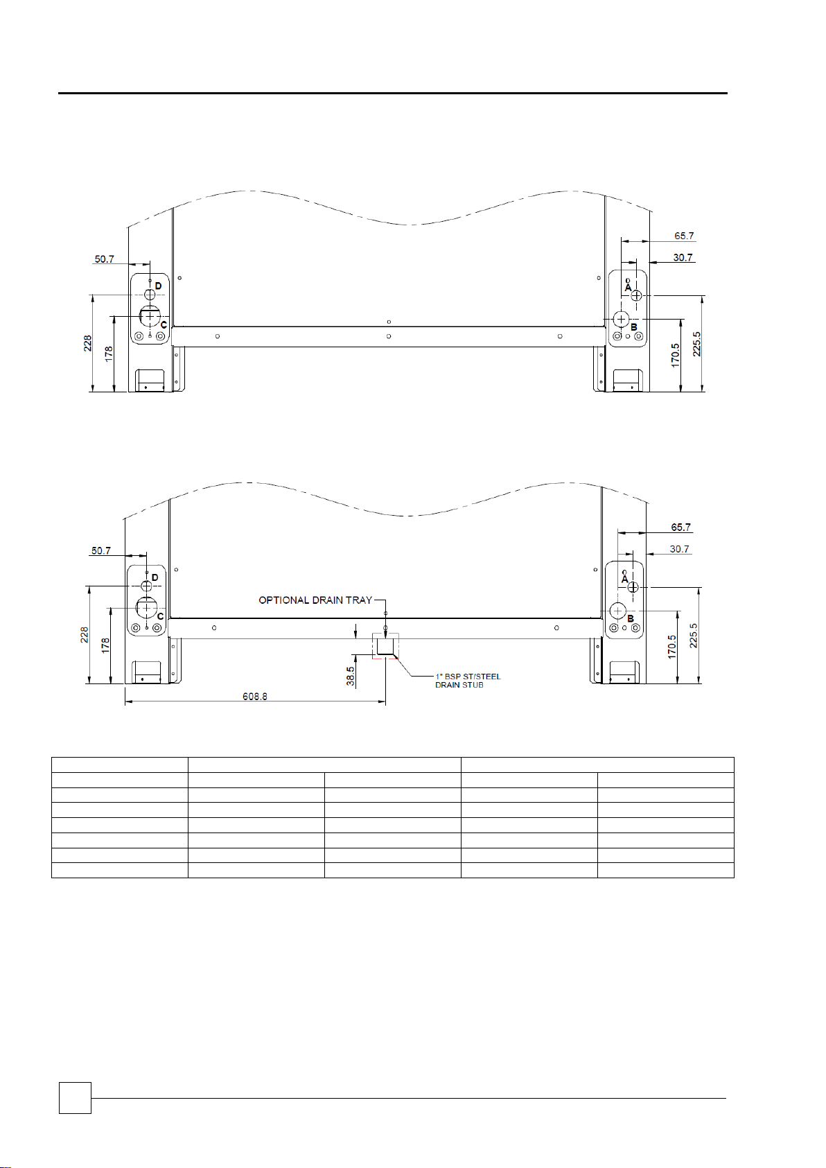
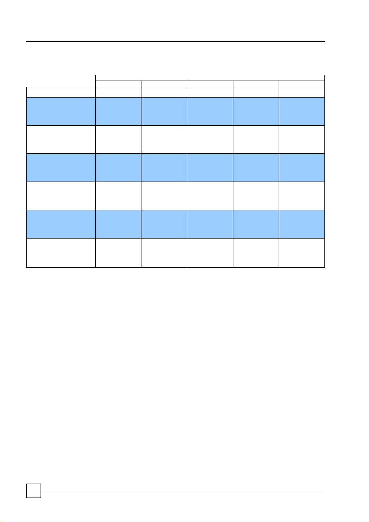
Wiring Access Holes (mm)
Pipe Work Hole Sizes (mm)
Cooling Only A B C D
CUR092V16
25
38
50
25
CUR092V20
25
38
50
25
CUR092V25
25
38
50
25
CUR092V29
25
38
50
25
Heat Pump
CUR092V16
25
38
38
25
CUR092V20
25
38
38
25
CUR092V25
25
38
38
25
CUR092V29
25
38
38
25
Incoming Services
Cooling only 092
Heat Pump 092
BluCube™
Condensing Unit
18
Condensing Units
Installation and Maintenance Manual : 7222094 11/2013
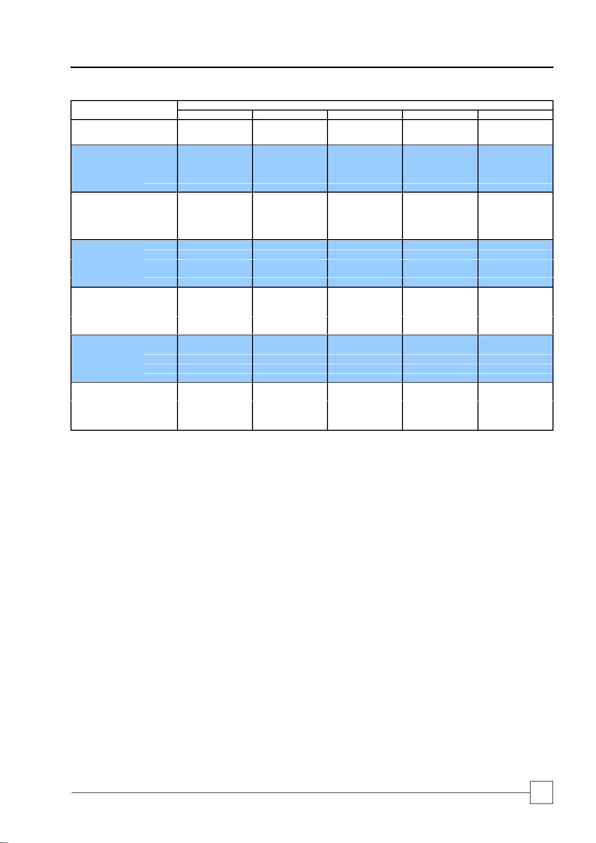
Wiring Access Holes (mm)
Pipe Work Hole Sizes (mm)
Cooling Only A B C D
CUR122V35
25
38
50
25
CUR122V40
25
38
50
25
Heat Pump
CUR122V35
25
38
50
25
CUR122V40
25
38
50
25
Cooling Only 122
Heat Pump 122

Condensing Units
BluCube™
Condensing Units
19
Installation and Maintenance Manual 7222094: 11/2013
Refrigeration Information
Pipework Installation
General
Special consideration should be given to vertical pipe runs and heat pump installation.
When insulating refrigerant lines, cut approximately 30 - 50cm longer than the distance
between the units to ensure the insulation goes right up to the unit. Leave connections
uncovered for leak testing.
Remove burrs to the ends of the copper tube, holding the tube downward to avoid
allowing dirt to contaminate the tube.
The installation of a sight glass close to the indoor unit is recommended.
Pressure Testing
When installation is complete, the system should be pressure tested.
Fill the system with dry nitrogen to a pressure of between 17 bar/250psig and 34bar/
500 psig.
NOTE: The LP switch must be disconnected for pressures above 17bar/250 psig.
Record the pressure over a minimum of 60 minutes to detect major leaks (a 24 hour
period should preferably be allowed).
If a reduction in pressure is detected, trace the leak and repair before conducting a further
pressure test and charging.
Evacuation
Evacuation for systems operating with R410A refrigerant to be carried out as follows.
Use a high vacuum pump and connect to the high and low pressure sides of the system
via a gauge manifold fitted with compound gauges. A high vacuum gauge should be fitted
to the system at the furthest point from the vacuum pump.
Triple evacuation should be used to ensure that all contaminants are removed.
Operate the vacuum pump until a pressure of 1.5 torr (200 Pa) absolute pressure is
reached, then stop the vacuum pump to break the vacuum using Nitrogen (Oxygen free)
until the pressure rises above zero.
The above operation should be repeated a second time.
The system should then be evacuated a third time but this time to 0.5 torr absolute
pressure.
Break with the correct refrigerant, until pressures equalise between the charging bottle
and the system.
IMPORTANT
Ensure all valves within the system are open during pressure testing / evacuation.

BluCube™
Condensing Unit
20
Condensing Units
Installation and Maintenance Manual : 7222094 11/2013
Refrigeration Pipework Installation - Good Practices
Oil Traps
For long vertical rises in both suction and discharge lines, it is essential that oil traps are
located every 4m to ensure proper oil movement / entrapment. In addition there should
be an oil trap at the exit of the air handling unit before a vertical riser is applied (refer to
example below).
Pipe Supports
The following table identifies the maximum
distance between pipe supports on vertical
and horizontal pipe runs.
Pipe O/D (inches)
Support distance (m)
3/8 - 7/8
1.0
1 1/8 - 2 1/8
2.0
CAUTION
All pipework should be clamped prior to insulation being applied (Suction Line).
Clamping over insulation is not acceptable.
Horizontal Sections
It is good practice to ensure a slight gradient toward the compressor in the direction of
the refrigerant flow for suction lines running horizontal. This assists oil return to the
compressor. A gradient of approximately 1:200 (0.5%) shall be used.
Condensing Unit Above Air Handling Unit
Condensing Unit Below Air Handling Unit
- - - - -Suction Line ……….. Liquid
Note the diagram above is for illustration only.
IMPORTANT
The pipe sizes and refrigerant charges quoted are for guidance only. It is the responsibility of the installing
contractor/site engineer to check the pipe size/refrigerant charge is correct for each system installation
and application.
Split systems may require additional oil which should be added to the low pressure side of each compressor.
Design should be in accordance with accepted refrigeration practice to ensure good oil return to the
compressor(s) under all normal operating conditions.
REMEMBER excessive pressure loss in interconnecting pipework will impair system performance; this should
be factored in during the design of the system and where necessary oil traps employed.
Traps are required every
4m of vertical rise.
Installation Data

Condensing Units
BluCube™
Condensing Units
21
Installation and Maintenance Manual 7222094: 11/2013
Pipework Schematics
Cooling Only – Fixed Capacity

BluCube™
Condensing Unit
22
Condensing Units
Installation and Maintenance Manual : 7222094 11/2013
Pipework Schematics
Cooling Only – Digital Scroll

Condensing Units
BluCube™
Condensing Units
23
Installation and Maintenance Manual 7222094: 11/2013
Pipework Schematics
Heat Pump

BluCube™
Condensing Unit
24
Condensing Units
Installation and Maintenance Manual : 7222094 11/2013
Pipework Schematics
Heat Pump

Condensing Units
BluCube™
Condensing Units
25
Installation and Maintenance Manual 7222094: 11/2013
Pipework Schematics
Heat Pump

BluCube™
Condensing Unit
26
Condensing Units
Installation and Maintenance Manual : 7222094 11/2013
Equivalent Pipe Lengths with R410A
Outdoor
Unit
0-20m
Suction
20-40m
Suction
40-60m
Suction
60-80m
Suction
Connection Size
Liquid
Suction
Liquid H V
Liquid H V
Liquid H V
Liquid H V
(3)
(1)
(2)
(3)
(1)
(2)
(3)
(1)
(2)
(3)
(1)
(2)
CUR092V16-1CO-0
3/8
7/8
1/2
1 1/8
7/8
1/2
1 1/8
7/8
1/2
1 1/8
7/8
1/2
1 1/8
7/8
CUR092V20-1CO-0
1/2
1 1/8
1/2
1 3/8
7/8
5/8
1 3/8
1 1/8
5/8
1 3/8
1 1/8
5/8
1 3/8
1 1/8
CUR092V25-1CO-0
1/2
1 3/8
1/2
1 3/8
1 1/8
5/8
1 3/8
1 1/8
5/8
1 3/8
1 1/8
5/8
1 3/8
1 1/8
CUR092V29-1CO-0
1/2
1 3/8
5/8
1 5/8
1 3/8
5/8
1 5/8
1 3/8
3/4
1 5/8
1 3/8
3/4
1 5/8
1 3/8
CUR122V35-1CO-0
5/8
1 3/8
3/4
1 5/8
1 3/8
3/4
1 5/8
1 3/8
3/4
1 5/8
1 5/8
3/4
1 5/8
1 5/8
CUR122V40-1CO-0
5/8
1 5/8
3/4
1 5/8
1 5/8
3/4
1 5/8
1 5/8
3/4
1 5/8
1 5/8
3/4
1 5/8
1 5/8
CUR092V16-VCO-0
3/8
7/8
1/2
1 1/8
7/8
1/2
1 1/8
7/8
1/2
1 1/8
7/8
1/2
1 1/8
7/8
CUR092V20-VCO-0
1/2
1 1/8
1/2
1 3/8
1 1/8
1/2
1 3/8
1 1/8
5/8
1 3/8
1 1/8
5/8
1 3/8
1 1/8
CUR092V25-VCO-0
1/2
1 3/8
1/2
1 3/8
1 1/8
5/8
1 3/8
1 1/8
5/8
1 3/8
1 1/8
5/8
1 3/8
1 1/8
CUR092V29-VCO-0
1/2
1 3/8
5/8
1 5/8
1 3/8
5/8
1 5/8
1 3/8
5/8
1 5/8
1 3/8
5/8
1 5/8
1 3/8
CUR122V35-VCO-0
5/8
1 3/8
3/4
1 5/8
1 3/8
3/4
1 5/8
1 3/8
3/4
1 5/8
1 3/8
3/4
1 5/8
1 3/8
CUR122V40-VCO-0
5/8
1 5/8
3/4
1 5/8
1 5/8
3/4
1 5/8
1 5/8
3/4
1 5/8
1 5/8
7/8
1 5/8
1 5/8
Equivalent Pipe Lengths with R410A
Outdoor
Unit
Connection Size
0-
20m Suction /
Disch
20-
40m
Suction /
Disch
40-
60m
Suction /
Disch
60-
80m
Suction /
Disch
Liquid
Suction
Disch
Liq
H V Liquid H V
Liquid H V
Liquid H V
(3)
(1)
(2)
(3)
(1)
(2)
(3)
(1)
(2)
(3)
(1)
(2)
CUR092V16-1HP-
3/8
1/2
1/2
3/4
1/2
1/2
3/4
5/8
1/2
3/4
5/8
1/2
3/4
5/8
CUR092V20-1HP-
3/8
5/8
1/2
7/8
5/8
5/8
7/8
5/8
5/8
7/8
5/8
5/8
7/8
5/8
CUR092V25-1HP-
1/2
7/8
1/2
1 1/8
5/8
5/8
1 1/8
3/4
5/8
1 1/8
3/4
5/8
1 1/8
3/4
CUR092V29-1HP-
1/2
7/8
5/8
1 1/8
3/4
5/8
1 1/8
3/4
3/4
1 1/8
3/4
3/4
1 1/8
3/4
CUR122V35-1HP-
1/2
7/8
3/4
1 3/8
7/8
3/4
1 3/8
7/8
3/4
1 3/8
7/8
3/4
1 3/8
7/8
CUR122V40-1HP-
5/8
1 1/8
3/4
1 3/8
7/8
3/4
1 3/8
7/8
3/4
1 3/8
7/8
3/4
1 3/8
7/8
CUR092V16-VHP-
3/8
1/2
1/2
7/8
1/2
1/2
7/8
1/2
1/2
7/8
1/2
1/2
7/8
1/2
CUR092V20-VHP-
3/8
5/8
1/2
7/8
5/8
1/2
7/8
5/8
5/8
7/8
5/8
5/8
7/8
5/8
CUR092V25-VHP-
1/2
7/8
1/2
1 1/8
5/8
5/8
1 1/8
5/8
5/8
1 1/8
5/8
5/8
1 1/8
5/8
CUR092V29-VHP-
1/2
7/8
5/8
1 1/8
3/4
5/8
1 1/8
3/4
5/8
1 1/8
3/4
5/8
1 1/8
3/4
CUR122V35-VHP-
1/2
7/8
3/4
1 3/8
3/4
3/4
1 3/8
3/4
3/4
1 3/8
3/4
3/4
1 3/8
3/4
CUR122V40-VHP-
5/8
1 1/8
3/4
1 3/8
7/8
3/4
1 3/8
7/8
3/4
1 3/8
7/8
7/8
1 3/8
7/8 (1) For interconnecting pipework with a predominantly horizontal layout.
(2) For interconnecting pipework with a predominantly vertical layout.
(3) Careful pipework selection must be done if the liquid line rises. Additional system sub cooling may be required to overcome friction losses.
All pipe sizes have been calculated based on a nominal condition 7°C evaporating and 50°C condensing
Suction and discharge double risers may be required for modulating capacity units at part load.
Refrigeration Pipe Sizing Guide
Cooling Only
Heat Pump

Condensing Units
BluCube™
Condensing Units
27
Installation and Maintenance Manual 7222094: 11/2013
Typical Cooling Application Envelope
12, -20
12, 42
15, 45
28, 45
28, -20
-30
-20
-10
0
10
20
30
40
50
0 5 10 15 20 25 30
Return Air Temperature (°C)
Ambient Temperature (°C)
Operating Limits - Cooling Only
3, 48
15, -20
15, 48
-23, 23
-23, -20
-30
-20
-10
0
10
20
30
40
50
60
-25 -20 -15 -10 -5 0 5 10 15 20
Evaporating temperature (°C)
Ambient temperature (°C)
Technical Data Cooling Only
Operational Limits
Data based upon a 12°C T across the indoor heat exchanger.
BluCube™
Condensing Unit
28
Condensing Units
Installation and Maintenance Manual : 7222094 11/2013
Ambient (°C)
25
30
35
40
45
Unit
TEvap
(°C)
Output
(kW)
Input
(kW)
Output
(kW)
Input
(kW)
Output
(kW)
Input
(kW)
Output
(kW)
Input
(kW)
Output
(kW)
Input
(kW)
CUR092V16-1CO-0
-5
9.6
3.8
9.6
3.8
9.2
4.0
8.6
4.4
8.0
4.8 0 11.5
3.8
11.5
3.8
11.0
4.0
10.3
4.4
9.6
4.9 5 13.8
3.8
13.7
3.7
13.0
4.1
12.2
4.5
11.5
4.9 7 14.8
3.8
14.7
3.7
13.8
4.1
13.0
4.5
12.2
4.9
10
16.4
3.8
16.2
3.7
15.2
4.1
14.3
4.5
13.5
5.0
CUR092V20-1CO-0
-5
14.7
5.5
14.5
5.5
13.7
5.9
12.7
6.4
11.7
6.9 0 17.6
5.4
17.2
5.6
16.2
6.0
15.2
6.5
14.1
7.0 5 21.1
5.3
20.2
5.6
19.1
6.1
17.9
6.6
16.8
7.2 7 22.6
5.3
21.5
5.7
20.3
6.2
19.1
6.7
17.9
7.2
10
25.0
5.3
23.6
5.7
22.2
6.2
20.9
6.7
19.6
7.3
CUR092V25-1CO-0
-5
19.2
6.8
18.6
7.1
17.5
7.7
16.4
8.4
N/A
N/A 0 23.2
6.9
22.1
7.4
20.9
8.0
19.5
8.7
18.0
9.5 5 27.6
7.1
26.1
7.7
24.5
8.3
22.8
9.0
21.0
9.8 7 29.4
7.2
27.7
7.8
26.0
8.4
24.2
9.1
22.3
9.9
10
32.1
7.5
30.3
8.0
28.4
8.7
26.5
9.3
24.3
10.1
CUR092V29-1CO-0
-5
21.8
7.5
20.7
8.0
19.3
8.7
17.9
9.5
N/A
N/A 0 26.1
7.6
24.5
8.3
22.9
9.0
21.2
9.9
19.4
10.8 5 30.6
8.0
28.8
8.6
26.9
9.4
24.9
10.2
22.8
11.1 7 32.5
8.1
30.6
8.8
28.6
9.5
26.5
10.4
24.3
11.3
10
35.4
8.3
33.4
9.0
31.2
9.8
28.9
10.6
26.5
11.5
CUR122V35-1CO-0
-5
28.5
9.4
27.9
12.0
26.1
13.0
24.2
14.1
22.2
15.3 0 34.3
9.8
33.1
12.3
31.0
13.3
28.8
14.4
26.4
15.6 5 41.0
11.2
38.9
12.7
36.5
13.6
33.9
14.7
31.1
15.9 7 43.7
11.9
41.3
12.8
38.8
13.8
36.1
14.8
33.1
16.1
10
47.8
12.2
45.2
13.0
42.4
14.0
39.5
15.1
36.3
16.3
CUR122V40-1CO-0
-5
32.7
11.0
31.6
13.6
29.6
14.5
27.6
15.6
N/A
N/A 0 39.3
12.5
37.3
14.0
35.0
15.0
32.6
16.1
30.0
17.3 5 46.2
13.6
43.6
14.5
40.9
15.5
38.1
16.6
35.0
17.9 7 49.0
13.8
46.3
14.8
43.4
15.7
40.4
16.9
37.2
18.1
10
53.5
14.2
50.5
15.1
47.4
16.1
44.1
17.2
40.6
18.5
Cooling Only Fixed Capacities
Notes:
1 Output kW refers to the compressor duty.
2 Input kW refers to the compressor and fan input power only.

Condensing Units
BluCube™
Condensing Units
29
Installation and Maintenance Manual 7222094: 11/2013
Ambient (°C)
25
30
35
40
45
Unit
TEvap
(°C)
Output
(kW)
Input
(kW)
Output
(kW)
Input
(kW)
Output
(kW)
Input
(kW)
Output
(kW)
Input
(kW)
Output
(kW)
Input
(kW)
CUR092V16-VCO-0
-5
10.9
4.0
10.9
4.1
10.4
4.2
9.7
4.7
9.0
5.1
0
13.1
4.1
13.1
4.1
12.4
4.4
11.6
4.8
10.7
5.2 5 15.7
4.2
15.6
4.1
14.7
4.5
13.7
4.9
12.7
5.4 7 16.8
4.2
16.6
4.1
15.6
4.5
14.6
5.0
13.5
5.5
10
18.6
4.2
18.3
4.2
17.2
4.6
16.0
5.1
14.8
5.6
CUR092V20-VCO-0
-5
14.9
5.3
14.8
5.2
13.9
5.8
12.9
6.3
12.0
6.9
0
17.8
5.4
17.4
5.4
16.4
5.9
15.3
6.5
14.1
7.1
5
21.1
5.4
20.3
5.6
19.1
6.1
17.8
6.7
16.5
7.4 7 22.5
5.4
21.6
5.7
20.3
6.2
18.9
6.8
17.5
7.5
10
24.7
5.4
23.5
5.8
22.1
6.4
20.6
7.0
19.1
7.6
CUR092V25-VCO-0
-5
18.5
6.2
18.0
6.4
16.9
7.1
15.6
7.9
N/A
N/A 0 22.2
6.2
21.3
6.6
20.0
7.2
18.6
8.0
17.1
8.9
5
26.3
6.2
24.9
6.8
23.4
7.5
21.8
8.2
20.0
9.1
7
28.0
6.3
26.4
6.9
24.8
7.6
23.1
8.3
21.3
9.1
10
30.5
6.5
28.7
7.1
27.0
7.7
25.1
8.5
23.2
9.3
CUR092V29-VCO-0
-5
21.9
7.2
20.8
7.7
19.4
8.6
17.8
9.6
N/A
N/A 0 26.1
7.2
24.6
8.0
22.9
8.8
21.1
9.8
19.2
10.9 5 30.4
7.5
28.7
8.2
26.8
9.1
24.7
10.0
22.5
11.1
7
32.3
7.6
30.4
8.3
28.4
9.2
26.2
10.1
23.9
11.2
10
35.1
7.8
33.1
8.5
30.9
9.4
28.5
10.3
26.0
11.4
CUR122V35-VCO-0
-5
27.5
9.0
27.0
11.5
25.5
12.4
23.8
13.4
21.9
14.6 0 32.8
9.2
31.9
11.8
30.0
12.7
28.0
13.7
25.8
14.9 5 39.0
10.2
37.2
12.2
35.0
13.1
32.6
14.1
30.0
15.2 7 41.7
11.1
39.5
12.3
37.1
13.2
34.5
14.2
31.8
15.4
10
45.7
11.7
43.1
12.6
40.5
13.5
37.6
14.5
34.6
15.6
CUR122V40-VCO-0
-5
32.9
10.9
31.9
13.5
30.2
14.5
28.3
15.7
N/A
N/A 0 38.8
12.1
37.1
13.9
35.0
14.9
32.8
16.1
30.4
17.4 5 45.2
13.4
42.8
14.3
40.3
15.4
37.7
16.5
34.8
17.8 7 47.9
13.5
45.3
14.5
42.6
15.5
39.8
16.7
36.7
18.0
10
52.1
13.8
49.2
14.8
46.2
15.8
43.0
17.0
39.7
18.3
Cooling Only Modulating Capacities
Notes:
1 Output kW refers to the compressor duty.
2 Input kW refers to the compressor and fan input power only.

BluCube™
Condensing Unit
30
Condensing Units
Installation and Maintenance Manual : 7222094 11/2013
CUR092V16-1CO-0
CUR092V20-1CO-0
CUR092V25-1CO-0
Capacity
Nominal Cooling Capacity
(1)
kW
13.8
20.3
26.0
Capacity Steps
1 1 1
Dimensions – W x D x H
(2)
mm
922 x 764 x 1736
922 x 764 x 1736
922 x 764 x 1736
Masses – Machine / Operating
(3)
kg
212
213
241
Construction
Panels: Galvanised Sheet Steel, Epoxy Baked Powder Paint – Light Grey (RAL 7035)
Material/Colour
Condenser
Rifled Copper Tube/Louvered Hydrophilic Coated Aluminium Fins
Fan Motor
Axial
Motor Type
AC 1ph
AC 1ph
AC 1ph
Quantity x Motor Size
kW
1 x 0.6
1 x 0.6
1 x 0.6
Diameter
mm
630
630
630
Maximum Fan Speed
RPM
860
860
860
Maximum Airflow
m³/s
2.0
2.0
2.0
Compressor
Compressor Type
Fixed Capacity Scroll
Quantity
1 1 1
Oil Charge Volume
l
1.57
1.57
3.3
Oil Type
Polyolester
Refrigeration
Single Circuit - 2 pipe configuration
Refrigerant control and type
Optional REEV package
Refrigerant type
R410A
Holding Charge
Inert Gas
Coil Volume
l
9.9
9.9
9.9
Refrigerant Charge
(4)
kg
5.7
5.8
5.8
Connections
Liquid (sweat)
in
3/8
1/2
1/2
Suction (sweat)
in
7/8
1 1/8
1 3/8
Optional Extras
EC Fan
Quantity x Motor Size
kW
1 x 0.72
1 x 0.72
1 x 0.72
Diameter
mm
630
630
630
Maximum Fan Speed
RPM
1000
1000
1000
Maximum Airflow
m³/s
2.3
2.3
2.3
Dimensions – W x D x H
(2)
mm
922 x 764 x 1750
922 x 764 x 1750
922 x 764 x 1750
Masses – Machine / Operating
(3)
kg
204
205
232
Short Case Axial Fan
Designed to 75Pa ESP
Quantity x Motor Size
kW
1 x 1.4
1 x 1.4
1 x 1.4
Diameter
mm
560
560
560
Maximum Fan Speed
RPM
1330
1330
1330
Maximum Airflow
m³/s
2.8
2.8
2.8
Dimensions – W x D x H
(2)
mm
922 x 764 x 1753
922 x 764 x 1753
922 x 764 x 1753
Masses – Machine / Operating
(3)
kg
218
219
247
REEV Selection
E²V -24
E²V – 35
E²V - 35
(1) Evaporating temperature 7°C, Ambient 35°C with an AC fan matched with a REEV package
(2) Overall dimensions for clearance
(3) Unit mass excludes a refrigerant charge
(4) For guidance only
Mechanical Data Cooling Only Fixed Capacities

Condensing Units
BluCube™
Condensing Units
31
Installation and Maintenance Manual 7222094: 11/2013
CUR092V29-1CO-0
CUR122V35-1CO-0
CUR122V40-1CO-0
Capacity
Nominal Cooling Capacity
(1)
kW
28.6
38.8
43.4
Capacity Steps
1 1 1
Dimensions – W x D x H
(2)
mm
922 x 764 x 1736
1222 x 764 x 1736
1222 x 764 x 1736
Masses – Machine / Operating
(3)
kg
241
292
296
Construction
Panels: Galvanised Sheet Steel, Epoxy Baked Powder Paint – Light Grey (RAL 7035)
Material/Colour
Condenser
Rifled Copper Tube/Louvered Hydrophilic Coated Aluminium Fins
Fan Motor
Axial
Motor Type
AC 1ph
AC 3ph
AC 3ph
Quantity x Motor Size
kW
1 x 0.6
1 x 1.97
1 x 1.97
Diameter
mm
630
630
630
Maximum Fan Speed
RPM
860
1330
1330
Maximum Airflow
m³/s
2.0
3.5
3.5
Compressor
Compressor Type
Fixed Capacity Scroll
Quantity
1 1 1
Oil Charge Volume
l
3.3
3.3
3.6
Oil Type
Polyolester
Refrigeration
Single Circuit - 2 pipe configuration
Refrigerant control and type
Optional REEV package
Refrigerant type
R410A
Holding Charge
Inert Gas
Coil Volume
l
9.9
12.4
12.4
Refrigerant Charge
(4)
kg
5.8
7.3
7.4
Connections
Liquid (sweat)
in
1/2
5/8
5/8
Suction (sweat)
in
1 3/8
1 3/8
1 5/8
Optional Extras
EC Fan
Quantity x Motor Size
kW
1 x 0.72
1 x 1.85
1 x 1.85
Diameter
mm
630
630
630
Maximum Fan Speed
RPM
1000
1230
1230
Maximum Airflow
m³/s
2.3
3.5
3.5
Dimensions – W x D x H
(2)
mm
922 x 764 x 1750
1222 x 764 x 1750
1222 x 764 x 1750
Masses – Machine / Operating
(3)
kg
233
284
287
Short Case Axial Fan
Designed to 75Pa ESP
Quantity x Motor Size
kW
1 x 1.4
N/A
N/A
Diameter
mm
560
N/A
N/A
Maximum Fan Speed
RPM
1330
N/A
N/A
Maximum Airflow
m³/s
2.8
N/A
N/A
Dimensions – W x D x H
(2)
mm
922 x 764 x 1753
N/A
N/A
Masses – Machine / Operating
(3)
kg
247
N/A
N/A
REEV Selection
E²V – 35
E²V - 45
E²V - 45
(1) Evaporating temperature 7°C, Ambient 35°C with an AC fan matched with a REEV package
(2) Overall dimensions for clearance
(3) Unit mass excludes a refrigerant charge
(4) For guidance only
Mechanical Data Cooling Only Fixed Capacities Continued

BluCube™
Condensing Unit
32
Condensing Units
Installation and Maintenance Manual : 7222094 11/2013
CUR092V16-VCO-0
CUR092V20-VCO-0
CUR092V25-VCO-0
Capacity
Nominal Cooling Capacity
(1)
kW
15.6
20.3
24.8
Capacity Steps
16-100%
16-100%
16-100%
Dimensions – W x D x H
(2)
mm
922 x 764 x 1736
922 x 764 x 1736
922 x 764 x 1736
Masses – Machine / Operating
(3)
kg
219
220
241
Construction
Panels: Galvanised Sheet Steel, Epoxy Baked Powder Paint – Light Grey (RAL 7035)
Material/Colour
Condenser
Rifled Copper Tube/Louvered Hydrophilic Coated Aluminium Fins
Fan Motor
Axial
Motor Type
AC 1ph
AC 1ph
AC 1ph
Quantity x Motor Size
kW
1 x 0.6
1 x 0.6
1 x 0.6
Diameter
mm
630
630
630
Maximum Fan Speed
RPM
860
860
860
Maximum Airflow
m³/s
2.0
2.0
2.0
Compressor
Compressor Type
Modulating Capacity Scroll
Quantity
1 1 1
Oil Charge Volume
l
1.9
1.9
3.2
Oil Type
Polyolester
Refrigeration
Single Circuit - 2 pipe configuration
Refrigerant control and type
Optional REEV package
Refrigerant type
R410A
Holding Charge
Inert Gas
Coil Volume
l
9.9
9.9
9.9
Refrigerant Charge
(4)
kg
5.7
5.7
5.8
Connections
Liquid (sweat)
in
3/8
1/2
1/2
Suction (sweat)
in
7/8
1 1/8
1 3/8
Optional Extras
EC Fan
Quantity x Motor Size
kW
1 x 0.72
1 x 0.72
1 x 0.72
Diameter
mm
630
630
630
Maximum Fan Speed
RPM
1000
1000
1000
Maximum Airflow
m³/s
2.3
2.3
2.3
Dimensions – W x D x H
(2)
mm
922 x 764 x 1750
922 x 764 x 1750
922 x 764 x 1750
Masses – Machine / Operating
(3)
kg
211
212
233
Short Case Axial Fan
Designed to 75Pa ESP
Quantity x Motor Size
kW
1 x 1.4
1 x 1.4
1 x 1.4
Diameter
mm
560
560
560
Maximum Fan Speed
RPM
1330
1330
1330
Maximum Airflow
m³/s
2.8
2.8
2.8
Dimensions – W x D x H
(2)
mm
922 x 764 x 1753
922 x 764 x 1753
922 x 764 x 1753
Masses – Machine / Operating
(3)
kg
218
219
247
REEV Selection
E²V – 24
E²V - 35
E²V - 35
(1) Evaporating temperature 7°C, Ambient 35°C with an AC fan matched with a REEV package
(2) Overall dimensions for clearance
(3) Unit mass excludes a refrigerant charge
(4) For guidance only
Mechanical Data Cooling Only Modulating Capacities

Condensing Units
BluCube™
Condensing Units
33
Installation and Maintenance Manual 7222094: 11/2013
CUR092V29-VCO-0
CUR122V35-VCO-0
CUR122V40-VCO-0
Capacity
Nominal Cooling Capacity
(1)
kW
28.4
37.1
42.6
Capacity Steps
16-100%
16-100%
16-100%
Dimensions – W x D x H
(2)
mm
922 x 764 x 1736
1222 x 764 x 1736
1222 x 764 x 1736
Masses – Machine / Operating
(3)
kg
243
293
295
Construction
Panels: Galvanised Sheet Steel, Epoxy Baked Powder Paint – Light Grey (RAL 7035)
Material/Colour
Condenser
Rifled Copper Tube/Louvered Hydrophilic Coated Aluminium Fins
Fan Motor
Axial
Motor Type
AC 1ph
AC 3ph
AC 3ph
Quantity x Motor Size
kW
1 x 0.6
1 x 1.97
1 x 1.97
Diameter
mm
630
630
630
Maximum Fan Speed
RPM
860
1330
1330
Maximum Airflow
m³/s
2.0
3.5
3.5
Compressor
Compressor Type
Modulating Capacity Scroll
Quantity
1 1 1
Oil Charge Volume
l
3.2
3.2
3.2
Oil Type
Polyolester
Refrigeration
Single Circuit - 2 pipe configuration
Refrigerant control and type
Optional REEV package
Refrigerant type
R410A
Holding Charge
Inert Gas
Coil Volume
l
9.9
12.4
12.4
Refrigerant Charge
(4)
kg
5.8
7.3
7.4
Connections
Liquid (sweat)
in
1/2
5/8
5/8
Suction (sweat)
in
1 3/8
1 3/8
1 5/8
Optional Extras
EC Fan
Quantity x Motor Size
kW
1 x 0.72
1 x 1.85
1 x 1.85
Diameter
mm
630
630
630
Maximum Fan Speed
RPM
1000
1230
1230
Maximum Airflow
m³/s
2.3
3.5
3.5
Dimensions – W x D x H
(2)
mm
922 x 764 x 1750
1222 x 764 x 1750
1222 x 764 x 1750
Masses – Machine / Operating
(3)
kg
234
285
287
Short Case Axial Fan
Designed to 75Pa ESP
Quantity x Motor Size
kW
1 x 1.4
N/A
N/A
Diameter
mm
560
N/A
N/A
Maximum Fan Speed
RPM
1330
N/A
N/A
Maximum Airflow
m³/s
2.8
N/A
N/A
Dimensions – W x D x H
(2)
mm
922 x 764 x 1753
N/A
N/A
Masses – Machine / Operating
(3)
kg
247
N/A
N/A
REEV Selection
E²V – 35
E²V - 45
E²V - 45
(1) Evaporating temperature 7°C, Ambient 35°C with an AC fan matched with a REEV package
(2) Overall dimensions for clearance
(3) Unit mass excludes a refrigerant charge
(4) For guidance only
Mechanical Data Cooling Only Variable Capacities Continued

BluCube™
Condensing Unit
34
Condensing Units
Installation and Maintenance Manual : 7222094 11/2013
CUR092V16-1CO-0
CUR092V20-1CO-0
CUR092V25-1CO-0
Unit Data
(1)
Nominal Run Amps
A
11.5
16.9
19.4
Maximum Start Amps
A
73.7
103.7
145.7
Recommended Mains Fuse Size
A
20
32
32
Max Mains Incoming Cable Size
mm²
35
35
35
Mains Supply
V
400V / 3PH + N / 50Hz
Control circuit
VAC
24
24
24
Condenser Fan - Motor
Motor Type
AC
AC
AC
1~
1~
1~
Quantity x Motor Size
kW
1 x 0.6
1 x 0.6
1 x 0.6
Full Load Amps
A
2.7
2.7
2.7
Locked Rotor Amps
A
9.2
9.2
9.2
Compressor
Motor Size
kW
4.6
6.4
8.5
Nominal Run Amps
A
7.9
13.3
15.8
Locked Rotor Amps
A
70
100
142
Type of Start
Direct On Line
OPTIONAL EXTRAS
Electronic Soft-start
Nominal Run Amps
A
11.5
16.9
19.4
Maximum Start Amps
A
45.7
63.7
88.9
Recommended Mains Fuse Size
A
16
25
32
Power Factor Correction
Nominal Run Amps
A
11.2
16.5
18.6
Maximum Start Amps
A
73.7
103.7
145.7
Recommended Mains Fuse Size
A
20
32
32
Compressor Nominal Run Amps
A
7.5
12.8
14.9
First upgrade EC Motor
1~
1~
1~
Quantity x Motor Size
kW
1 x 0.72
1 x 0.72
1 x 0.72
Full Load Amps
A
3.3
3.3
3.3
Locked Rotor Amps
A
N/A
N/A
N/A
Second upgrade SCAF
1~
1~
1~
Quantity x Motor Size
kW
1 x 1.4
1 x 1.4
1 x 1.4
Full Load Amps
A
6 6 6
Locked Rotor Amps
A
18
18
18
Electrical Data – Cooling Only
(1) Based upon ARI conditions, Evaporating at 7°C, Condensing at 54.4°C.

Condensing Units
BluCube™
Condensing Units
35
Installation and Maintenance Manual 7222094: 11/2013
CUR092V29-1CO-0
CUR122V35-1CO-0
CUR122V40-1CO-0
Unit Data
(1)
Nominal Run Amps
A
20.6
25.1
29
Maximum Start Amps
A
145.7
162.4
201.4
Recommended Mains Fuse Size
A
32
40
50
Max Mains Incoming Cable Size
mm²
35
35
35
Mains Supply
V
400V / 3PH + N / 50Hz
Control circuit
VAC
24
24
24
Condenser Fan - Motor
Motor Type
AC
AC
AC
1~
3~
3~
Quantity x Motor Size
kW
1 x 0.6
1 x 1.97
1 x 1.97
Full Load Amps
A
2.7
3.4
3.4
Locked Rotor Amps
A
9.2
11.9
11.9
Compressor
Motor Size
kW
9.5
12.2
13.8
Nominal Run Amps
A
17
20.7
24.6
Locked Rotor Amps
A
142
158
197
Type of Start
Direct On Line
OPTIONAL EXTRAS
Electronic Soft-start
Nominal Run Amps
A
20.6
23.8
27.5
Maximum Start Amps
A
88.9
99.2
122.6
Recommended Mains Fuse Size
A
32
40
50
Power Factor Correction
Nominal Run Amps
A
19.8
23.8
29
Maximum Start Amps
A
145.7
162.4
201.4
Recommended Mains Fuse Size
A
32
40
50
Compressor Nominal Run Amps
A
16.2
19.4
23.1
First upgrade EC Motor
1~
3~
3~
Quantity x Motor Size
kW
1 x 0.72
1 x 1.85
1 x 1.85
Full Load Amps
A
3.3
2.9
2.9
Locked Rotor Amps
A
N/A
N/A
N/A
Second upgrade SCAF
1~
N/A
N/A
Quantity x Motor Size
kW
1 x 1.4
N/A
N/A
Full Load Amps
A
6
N/A
N/A
Locked Rotor Amps
A
18
N/A
N/A
Electrical Data – Cooling Only Continued
(1) Based upon ARI conditions, Evaporating at 7°C, Condensing at 54.4°C.

BluCube™
Condensing Unit
36
Condensing Units
Installation and Maintenance Manual : 7222094 11/2013
CUR092V16-VCO-0
CUR092V20-VCO-0
CUR092V25-VCO-0
Unit Data
(1)
Nominal Run Amps
A
12.2
15.7
18.2
Maximum Start Amps
A
67.7
104.7
114.7
Recommended Mains Fuse Size
A
20
25
25
Max Mains Incoming Cable Size
mm²
35
35
35
Mains Supply
V
400V / 3PH + N / 50Hz
Control circuit
VAC
24
24
24
Condenser Fan - Motor
Motor Type
AC
AC
AC
1~
1~
1~
Quantity x Motor Size
kW
1 x 0.6
1 x 0.6
1 x 0.6
Full Load Amps
A
2.7
2.7
2.7
Locked Rotor Amps
A
9.2
9.2
9.2
Compressor
Motor Size
kW
5 7 8
Nominal Run Amps
A
8.6
12.1
14.5
Locked Rotor Amps
A
64
101
111
Type of Start
Direct On Line
OPTIONAL EXTRAS
Electronic Soft-start
Nominal Run Amps
A
12.2
15.7
18.2
Maximum Start Amps
A
42.1
64.3
70.3
Recommended Mains Fuse Size
A
20
25
32
Power Factor Correction
N/A
N/A
N/A
Nominal Run Amps
A
N/A
N/A
N/A
Maximum Start Amps
A
N/A
N/A
N/A
Recommended Mains Fuse Size
A
N/A
N/A
N/A
Compressor Nominal Run Amps
A
N/A
N/A
N/A
First upgrade EC Motor
1~
1~
1~
Quantity x Motor Size
kW
1 x 0.72
1 x 0.72
1 x 0.72
Full Load Amps
A
3.3
3.3
3.3
Locked Rotor Amps
A
N/A
N/A
N/A
Second upgrade SCAF
1~
1~
1~
Quantity x Motor Size
kW
1 x 1.4
1 x 1.4
1 x 1.4
Full Load Amps
A
6 6 6
Locked Rotor Amps
A
18
18
18
Electrical Data – Cooling Only Continued
(1) Based upon ARI conditions, Evaporating at 7°C, Condensing at 54.4°C.

Condensing Units
BluCube™
Condensing Units
37
Installation and Maintenance Manual 7222094: 11/2013
CUR092V29-VCO-0
CUR122V35-VCO-0
CUR122V40-VCO-0
Unit Data
(1)
Nominal Run Amps
A
20.4
25.5
30.8
Maximum Start Amps
A
121.7
144.4
177.4
Recommended Mains Fuse Size
A
32
40
50
Max Mains Incoming Cable Size
mm²
35
35
35
Mains Supply
V
400V / 3PH + N / 50Hz
Control circuit
VAC
24
24
24
Condenser Fan - Motor
Motor Type
AC
AC
AC
1~
3~
3~
Quantity x Motor Size
kW
1 x 0.6
1 x 1.97
1 x 1.97
Full Load Amps
A
2.7
3.4
3.4
Locked Rotor Amps
A
9.2
11.9
11.9
Compressor
Motor Size
kW
9.4
11.8
13.9
Nominal Run Amps
A
16.8
21.1
26.4
Locked Rotor Amps
A
118
140
173
Type of Start
Direct On Line
OPTIONAL EXTRAS
Electronic Soft-start
Nominal Run Amps
A
20.4
25.5
30.8
Maximum Start Amps
A
74.5
88.4
108.2
Recommended Mains Fuse Size
A
32
40
50
Power Factor Correction
N/A
N/A
N/A
Nominal Run Amps
A
N/A
N/A
N/A
Maximum Start Amps
N/A
N/A
N/A
N/A
Recommended Mains Fuse Size
A
N/A
N/A
N/A
Compressor Nominal Run Amps
A
N/A
N/A
N/A
First upgrade EC Motor
1~
3~
3~
Quantity x Motor Size
kW
1 x 0.72
1 x 1.85
1 x 1.85
Full Load Amps
A
3.3
2.9
2.9
Locked Rotor Amps
A
N/A
N/A
N/A
Second upgrade SCAF
1~
N/A
N/A
Quantity x Motor Size
kW
1 x 1.4
N/A
N/A
Full Load Amps
A
6.0
N/A
N/A
Locked Rotor Amps
A
18
N/A
N/A
Electrical Data – Cooling Only Continued
(1) Based upon ARI conditions, Evaporating at 7°C, Condensing at 54.4°C.

BluCube™
Condensing Unit
38
Condensing Units
Installation and Maintenance Manual : 7222094 11/2013
BluCube
L1
Mains incoming supply 400V/3PH/50Hz
L2
L3
N
PE
502
24 Volts AC
551
Cooling Signal
845
Variable Capacity Compressor Only
0-10Volts Compressor demand
500
0 Volts
561
NO
Critical alarm Normally Open
562
Common
GND 563
NC
Critical alarm Normally Closed
Rx-Tx-
Use Awg20/22 twisted pair (with overall shield) cable,
Belden ref. 8762 (Airedale ref: 6110316), or equivalent,
for
network
Network Connections
(Inward connection)
Rx+Tx+
GND
Rx-Tx-
Use Awg20/22 twisted pair (with overall shield) cable,
Belden ref. 8762 (Airedale ref: 6110316), or equivalent,
for
network
Network Connections
(Outward connection)
Rx+Tx+
GND
Interconnecting Wiring

Condensing Units
BluCube™
Condensing Units
39
Installation and Maintenance Manual 7222094: 11/2013
Typical Heating Application Envelope
28, -13
26, -15
28, 25
12, 25
12, -15
-20
-15
-10
-5
0
5
10
15
20
25
30
0 5 10 15 20 25 30
Return Air Temperature (°C)
Ambient Temperature (°C)
CAUTION
A minimum air on temperature limit of 12°C must be adhered to ensure correct unit
operation.
Any fresh air introduced to the unit must have pre-heaters to maintain this
minimum temperature.
Operating Limits - Heat Pump Heating Cycle
-15, 25
-15, 38
25, 60
25, 25
13, 60
-20, 25
-20, 38
0
10
20
30
40
50
60
70
-25 -20 -15 -10 -5 0 5 10 15 20 25 30
Ambient temperature (°C)
Condensing temperature (°C)
Fixed Capacity Modulated Capacity
Technical Data Heat Pump
Operational Limits
Data Based on a 12°C T across coil.

BluCube™
Condensing Unit
40
Condensing Units
Installation and Maintenance Manual : 7222094 11/2013
Operating Limits - Heat Pump Cooling Cycle
-23, -20
-23, 23
15, 42
15, -20
3, 42
15, 48
3, 48
-30
-20
-10
0
10
20
30
40
50
60
-25 -20 -15 -10 -5 0 5 10 15 20
Evaporating temperature (°C)
Ambient temperature (°C)
Fixed Capacity Modulated Capacity
Condensing Units
BluCube™
Condensing Units
41
Installation and Maintenance Manual 7222094: 11/2013
Summer Ambient (°C)
25
30
35
40
45
Unit
Evap
Temp
(°C)
Output
(kW)
Input
(kW)
Output
(kW)
Input
(kW)
Output
(kW)
Input
(kW)
Output
(kW)
Input
(kW)
Output
(kW)
Input
(kW)
CUR092V16-1HP-0
-5
10.3
3.9
10.3
3.8
9.8
4.2
9.2
4.6
8.5
5.0 0 12.4
3.9
12.2
3.9
11.6
4.3
11.0
4.7
10.3
5.2 5 14.8
3.9
14.4
4.0
13.7
4.4
13.0
4.8
12.2
5.3 7 15.9
3.8
15.4
4.0
14.6
4.4
13.8
4.8
13.0
5.3
10
17.6
3.7
16.9
4.0
16.0
4.4
15.2
4.9
14.3
5.3
CUR092V20-1HP-0
-5
15.8
5.5
15.1
5.8
14.3
6.3
13.3
6.8
N/A
N/A 0 18.7
5.5
17.9
6.0
17.0
6.5
15.9
7.0
14.8
7.6 5 21.9
5.7
20.9
6.1
19.8
6.6
18.7
7.2
17.5
7.7 7 23.3
5.7
22.2
6.2
21.1
6.7
19.9
7.2
18.7
7.8
10
25.4
5.8
24.2
6.3
23.0
6.8
21.8
7.3
21.1
6.7
CUR092V25-1HP-0
-5
20.3
7.0
19.3
7.7
18.3
8.4
17.1
9.1
N/A
N/A 0 24.0
7.4
22.8
8.0
21.5
8.7
20.1
9.5
N/A
N/A 5 28.1
7.8
26.6
8.4
25.0
9.1
23.3
9.9
N/A
N/A 7 29.8
8.0
28.2
8.6
26.5
9.3
24.6
10.1
N/A
N/A
10
32.4
8.2
30.6
8.9
28.8
9.6
26.7
10.3
N/A
N/A
CUR092V29-1HP-0
-5
22.5
8.0
21.2
8.7
19.9
9.5
28.7
10.6
N/A
N/A 0 26.5
8.4
25.0
9.1
23.4
10.0
21.6
10.9
N/A
N/A 5 30.8
8.9
29.0
9.6
27.1
10.4
25.1
11.4
N/A
N/A 7 32.6
9.0
30.7
9.8
28.7
10.6
26.6
11.6
N/A
N/A
10
35.4
9.3
33.3
10.1
31.1
11.0
28.7
10.6
N/A
N/A
CUR122V35-1HP-0
-5
30.5
11.8
29.0
12.9
27.2
13.9
25.3
15.1
N/A
N/A 0 36.1
12.3
34.2
13.2
32.1
14.3
29.8
15.5
N/A
N/A 5 42.1
12.7
39.9
13.7
37.4
14.8
34.8
15.9
31.9
17.3 7 44.6
12.9
42.3
13.9
39.7
14.9
36.9
16.1
33.9
17.5
10
48.6
13.2
46.0
14.2
43.2
15.3
40.2
16.4
39.7
14.9
CUR122V40-1HP-0
-5
34.5
13.5
32.7
14.5
30.7
15.6
28.6
16.8
N/A
N/A 0 40.4
14.1
38.3
15.1
36.0
16.2
33.5
17.4
N/A
N/A 5 46.9
14.8
44.4
15.7
41.7
16.8
38.8
18.1
N/A
N/A 7 49.6
15.0
47.0
16.0
44.1
17.1
41.0
18.4
N/A
N/A
10
53.9
15.4
51.0
16.5
47.8
17.6
44.5
18.8
N/A
N/A
Heat Pump Cooling Fixed Capacities
Notes:
1 Output kW refers to the compressor duty.
2 Input kW refers to the compressor and fan input power only.

BluCube™
Condensing Unit
42
Condensing Units
Installation and Maintenance Manual : 7222094 11/2013
Summer Ambient (°C)
25
30
35
40
45
Unit
Evap
Temp
(°C)
Output
(kW)
Input
(kW)
Output
(kW)
Input
(kW)
Output
(kW)
Input
(kW)
Output
(kW)
Input
(kW)
Output
(kW)
Input
(kW)
CUR092V16-VHP-0
-5
11.7
4.2
11.7
4.1
11.1
4.5
10.4
4.9
9.7
5.4 0 14.1
4.2
13.9
4.2
13.1
4.7
12.3
5.1
11.5
5.6 5 16.9
4.2
16.3
4.4
15.4
4.8
14.5
5.3
13.4
5.8 7 18.1
4.2
17.4
4.5
16.4
4.9
15.4
5.3
14.3
5.9
10
20.0
4.2
19.0
4.6
18.0
5.0
16.8
5.5
15.6
6.0
CUR092V20-VHP-0
-5
16.0
5.4
15.4
5.6
14.6
6.2
13.7
6.7
N/A
N/A 0 19.1
5.3
18.1
5.9
17.1
6.4
16.0
7.0
14.9
7.7 5 22.2
5.6
21.0
6.1
19.8
6.7
18.6
7.3
17.2
8.0 7 23.5
5.7
22.3
6.2
21.0
6.8
19.7
7.4
18.2
8.1
10
25.5
5.8
24.2
6.4
22.8
7.0
21.4
7.6
19.8
8.4
CUR092V25-VHP-0
-5
19.7
6.3
18.7
7.0
17.5
7.8
16.2
8.6
N/A
N/A 0 23.2
6.6
22.0
7.2
20.6
8.0
19.2
8.8
N/A
N/A 5 26.9
6.9
25.5
7.5
24.0
8.3
22.3
9.1
N/A
N/A 7 28.4
7.0
26.9
7.7
25.3
8.4
23.6
9.2
N/A
N/A
10
30.8
7.2
29.2
7.9
27.4
8.6
25.6
9.5
N/A
N/A
CUR092V29-VHP-0
-5
22.7
7.7
21.3
8.6
19.8
9.5
28.4
10.4
N/A
N/A 0 26.5
8.0
25.0
8.9
23.3
9.9
21.4
10.9
N/A
N/A 5 30.7
8.4
28.9
9.3
26.9
10.2
24.8
11.3
N/A
N/A 7 32.4
8.6
30.5
9.4
28.4
10.4
26.2
11.5
N/A
N/A
10
35.1
8.8
33.0
9.7
30.8
10.6
28.3
11.7
N/A
N/A
CUR122V35-VHP-0
-5
29.5
10.6
28.2
12.2
26.7
13.2
24.9
14.3
N/A
N/A 0 34.8
11.7
33.1
12.6
31.2
13.7
29.2
14.8
26.9
16.0 5 40.4
12.2
38.3
13.1
36.1
14.1
33.6
15.2
31.0
16.4 7 42.8
12.4
40.5
13.3
38.1
14.3
35.5
15.4
32.7
16.6
10
46.5
12.7
44.0
13.6
41.3
14.6
38.5
15.7
35.3
16.9
CUR122V40-VHP-0
-5
34.7
13.5
33.1
14.5
31.4
15.7
29.5
17.0
N/A
N/A 0 40.1
14.0
38.3
15.0
36.2
16.2
33.9
17.5
N/A
N/A 5 46.1
14.5
43.8
15.6
41.3
16.7
38.6
18.0
N/A
N/A 7 48.6
14.7
46.1
15.8
43.5
17.0
40.5
18.3
N/A
N/A
10
52.6
15.1
49.8
16.2
46.8
17.3
43.6
18.6
N/A
N/A
Heat Pump Cooling Modulating Capacities
Notes:
1 Output kW refers to the compressor duty.
2 Input kW refers to the compressor and fan input power only.

Condensing Units
BluCube™
Condensing Units
43
Installation and Maintenance Manual 7222094: 11/2013
Winter Ambient (°C)
-5 0 5
10
15
Unit
Cond
Temp
(°C)
Output
(kW)
Input
(kW)
Output
(kW)
Input
(kW)
Output
(kW)
Input
(kW)
Output
(kW)
Input
(kW)
Output
(kW)
Input
(kW)
CUR092V16-1HP-0
40
11.2
4.2
12.5
4.2
13.9
4.2
15.4
4.2
17.1
4.2
45
11.1
4.6
12.4
4.6
13.8
4.6
15.3
4.6
16.9
4.6
50
N/A
N/A
12.3
5.1
13.7
5.1
15.2
5.1
16.7
5.1
55
N/A
N/A
N/A
N/A
13.6
5.7
15.1
5.7
16.6
5.6
CUR092V20-1HP-0
40
16.0
6.0
17.8
6.0
19.7
6.0
21.7
6.0
23.9
6.0
45
15.8
6.5
17.7
6.6
19.6
6.6
21.5
6.6
23.7
6.6
50
N/A
N/A
17.4
7.1
19.4
7.2
21.3
7.2
23.4
7.2
55
N/A
N/A
N/A
N/A
N/A
N/A
21.1
7.8
23.1
7.8
CUR092V25-1HP-0
40
19.7
7.5
21.8
7.5
24.2
7.6
26.7
7.6
29.4
7.7
45
19.9
8.2
22.0
8.3
24.2
8.3
26.6
8.4
29.3
8.4
50
N/A
N/A
N/A
N/A
24.2
9.1
26.6
9.2
29.1
9.3
55
N/A
N/A
N/A
N/A
N/A
N/A
26.5
10.2
28.9
10.2
CUR092V29-1HP-0
40
21.6
8.2
24.0
8.3
26.5
8.3
29.2
8.4
32.0
8.5
45
21.7
9.0
24.0
9.1
26.4
9.2
29.0
9.3
31.8
9.3
50
N/A
N/A
N/A
N/A
26.4
10.2
28.9
10.2
31.6
10.3
55
N/A
N/A
N/A
N/A
N/A
N/A
28.8
11.3
31.4
11.4
CUR122V35-1HP-0
40
28.9
13.0
32.0
13.0
35.6
13.0
39.2
13.0
43.2
13.1
45
29.1
14.2
32.1
14.2
35.5
14.2
39.0
14.2
42.9
14.2
50
N/A
N/A
N/A
N/A
35.5
15.5
38.8
15.5
42.6
15.5
55
N/A
N/A
N/A
N/A
N/A
N/A
38.6
17.0
42.2
17.0
CUR122V40-1HP-0
40
32.0
14.0
35.4
14.2
39.4
14.3
43.3
14.4
47.8
14.6
45
32.2
15.2
35.5
15.3
39.3
15.5
43.1
15.6
47.5
15.7
50
N/A
N/A
N/A
N/A
39.2
16.8
42.9
16.9
47.1
17.0
55
N/A
N/A
N/A
N/A
N/A
N/A
42.7
18.4
46.7
18.5
Heat Pump Heating Fixed Capacities
Notes:
1 Output kW refers to the compressor duty.
2 Input kW refers to the compressor and fan input power only.

BluCube™
Condensing Unit
44
Condensing Units
Installation and Maintenance Manual : 7222094 11/2013
Winter Ambient (°C)
-5 0 5
10
15
Unit
Cond
Temp
(°C)
Output
(kW)
Input
(kW)
Output
(kW)
Input
(kW)
Output
(kW)
Input
(kW)
Output
(kW)
Input
(kW)
Output
(kW)
Input
(kW)
CUR092V16-VHP-0
40
12.1
4.4
13.6
4.4
15.2
4.5
17.0
4.5
18.9
4.6
45
12.1
4.8
13.6
4.9
15.1
5.0
16.8
5.0
18.6
5.1
50
N/A
N/A
13.5
5.4
15.0
5.5
16.6
5.5
18.3
5.6
55
N/A
N/A
N/A
N/A
14.8
6.0
16.4
6.1
18.0
6.2
CUR092V20-VHP-0
40
15.9
5.7
17.7
5.8
19.6
5.9
21.7
5.9
23.9
6.0
45
15.9
6.2
17.7
6.4
19.5
6.5
21.5
6.5
23.7
6.6
50
N/A
N/A
17.6
7.0
19.4
7.1
21.4
7.2
23.4
7.3
55
N/A
N/A
N/A
N/A
N/A
N/A
21.2
8.0
23.2
8.1
CUR092V25-VHP-0
40
19.0
7.0
21.0
7.0
23.2
7.0
25.5
7.0
28.0
7.0
45
19.1
7.9
21.1
7.8
23.2
7.8
25.4
7.7
27.8
7.7
50
N/A
N/A
21.1
8.8
23.2
8.7
25.3
8.6
27.7
8.6
55
N/A
N/A
N/A
N/A
N/A
N/A
25.3
9.7
27.5
9.6
CUR092V29-VHP-0
40
21.6
8.2
23.9
8.2
26.4
8.1
29.0
8.1
31.7
8.1
45
21.7
9.2
24.0
9.2
26.4
9.1
28.9
9.1
31.6
9.1
50
N/A
N/A
N/A
N/A
26.5
10.2
28.9
10.2
31.4
10.1
55
N/A
N/A
N/A
N/A
N/A
N/A
28.9
11.5
31.3
11.4
CUR122V35-VHP-0
40
27.9
12.3
31.0
12.4
34.5
12.4
37.9
12.5
41.8
12.6
45
28.1
13.4
31.1
13.5
34.5
13.5
37.8
13.6
41.6
13.7
50
N/A
N/A
N/A
N/A
34.4
14.8
37.7
14.8
41.3
14.9
55
N/A
N/A
N/A
N/A
N/A
N/A
37.5
16.2
40.9
16.3
CUR122V40-VHP-0
40
32.7
14.1
36.0
14.2
39.8
14.3
43.4
14.3
47.6
14.4
45
33.0
15.4
36.3
15.4
39.9
15.5
43.5
15.6
47.4
15.7
50
N/A
N/A
N/A
N/A
40.0
16.9
43.5
17.0
47.3
17.0
55
N/A
N/A
N/A
N/A
N/A
N/A
N/A
N/A
47.0
18.6
Heat Pump Heating Modulating Capacities
Notes:
1 Output kW refers to the compressor duty.
2 Input kW refers to the compressor and fan input power only.

Condensing Units
BluCube™
Condensing Units
45
Installation and Maintenance Manual 7222094: 11/2013
CUR092V16-1HP-0
CUR092V20-1HP-0
CUR092V25-1HP-0
Capacity
Nominal Cooling Capacity
(1)
kW
14.6
21.1
26.5
Nominal Heating Capacity
(2)
kW
13.7
19.4
24.2
Capacity Steps
1 1 1
Dimensions – W x D x H
(3)
mm
922 x 764 x 1736
922 x 764 x 1736
922 x 764 x 1736
Masses – Machine / Operating
(4)
kg
229
229
261
Construction
Panels: Galvanised Sheet Steel, Epoxy Baked Powder Paint – Light Grey (RAL 7035)
Material/Colour
Heat Pump Evaporator / Condenser
Rifled Copper Tube/Louvered Hydrophilic Coated Aluminium Fins
Fan Motor
Axial
Motor Type
AC 1ph
AC 1ph
AC 1ph
Quantity x Motor Size
kW
1 x 0.6
1 x 0.6
1 x 0.6
Diameter
mm
630
630
630
Maximum Fan Speed
RPM
860
860
860
Maximum Airflow
m³/s
2.0
2.0
2.0
Compressor
Compressor Type
Fixed Capacity Scroll
Quantity
1 1 1
Oil Charge Volume
1.57
1.57
3.3
Oil Type
Polyolester
Refrigeration
Single Circuit - 2 pipe configuration
Refrigerant control and type
Optional REEV package
Refrigerant type
R410A
Holding Charge
Inert Gas
Coil Volume
l
9.9
9.9
9.9
Refrigerant Charge
(5)
kg
8.4
8.5
8.9
Connections
Liquid (sweat)
in
3/8
3/8
1/2
Suction / Discharge (sweat)
in
1/2
5/8
7/8
Optional Extras
EC Fan
Quantity x Motor Size
kW
1 x 0.72
1 x 0.72
1 x 0.72
Diameter
mm
630
630
630
Maximum Fan Speed
RPM
1000
1000
1000
Maximum Airflow
m³/s
2.3
2.3
2.3
Dimensions – W x D x H
(2)
mm
922 x 764 x 1750
922 x 764 x 1750
922 x 764 x 1750
Masses – Machine / Operating
(3)
kg
221
221
253
Short Case Axial Fan
Designed to 75Pa ESP
Quantity x Motor Size
kW
1 x 1.4
1 x 1.4
1 x 1.4
Diameter
mm
560
560
560
Maximum Fan Speed
RPM
1330
1330
1330
Maximum Airflow
m³/s
2.8
2.8
2.8
Dimensions – W x D x H
(2)
mm
922 x 764 x 1753
922 x 764 x 1753
922 x 764 x 1753
Masses – Machine / Operating
(3)
kg
235
235
267
REEV Selection
E²V - 24
E²V - 35
E²V – 35
(1) Evaporating temperature 7°C, Ambient 35°C with an AC fan matched with a REEV package
(2) Condensing temperature 50°C, Ambient 5°C with an AC fan matched with a REEV package
(3) Overall dimensions for clearance
(4) Unit mass excludes a refrigerant charge
(5) For guidance only
Mechanical Data - Heat Pump Fixed Capacities

BluCube™
Condensing Unit
46
Condensing Units
Installation and Maintenance Manual : 7222094 11/2013
CUR092V29-1HP-0
CUR122V35-1HP-0
CUR122V40-1HP-0
Capacity
Nominal Cooling Capacity
(1)
kW
28.7
39.7
44.1
Nominal Heating Capacity
(2)
kW
26.4
35.5
39.2
Capacity Steps
1 1 1
Dimensions – W x D x H
(3)
mm
922 x 764 x 1736
1222 x 764 x 1736
1222 x 764 x 1736
Masses – Machine / Operating
(4)
kg
262
316
324
Construction
Panels: Galvanised Sheet Steel, Epoxy Baked Powder Paint – Light Grey (RAL 7035)
Material/Colour
Heat Pump Evaporator / Condenser
Rifled Copper Tube/Louvered Hydrophilic Coated Aluminium Fins
Fan Motor
Axial
Motor Type
AC 1ph
AC 3ph
AC 3ph
Quantity x Motor Size
kW
1 x 0.6
1 x 1.97
1 x 1.97
Diameter
mm
630
630
630
Maximum Fan Speed
RPM
860
1330
1330
Maximum Airflow
m³/s
2.0
3.5
3.5
Compressor
Compressor Type
Fixed Capacity Scroll
Quantity
1 1 1
Oil Charge Volume
l
3.3
3.3
3.6
Oil Type
Polyolester
Refrigeration
Single Circuit - 2 pipe configuration
Refrigerant control and type
Optional REEV package
Refrigerant type
R410A
Holding Charge
Inert Gas
Coil Volume
l
9.9
12.4
12.4
Refrigerant Charge
(5)
kg
8.9
10.9
11.7
Connections
Liquid (sweat)
in
1/2
1/2
5/8
Suction / Discharge (sweat)
in
7/8
7/8
1 1/8
Optional Extras
EC Fan
Quantity x Motor Size
kW
1 x 0.72
1 x 1.85
1 x 1.85
Diameter
mm
630
630
630
Maximum Fan Speed
RPM
1000
1230
1230
Maximum Airflow
m³/s
2.3
3.5
3.5
Dimensions – W x D x H
(2)
mm
922 x 764 x 1750
1222 x 764 x 1750
1222 x 764 x 1750
Masses – Machine / Operating
(3)
kg
254
308
316
Short Case Axial Fan
Designed to 75Pa ESP
Quantity x Motor Size
kW
1 x 1.4
N/A
N/A
Diameter
mm
560
N/A
N/A
Maximum Fan Speed
RPM
1330
N/A
N/A
Maximum Airflow
m³/s
2.8
N/A
N/A
Dimensions – W x D x H
(2)
mm
922 x 764 x 1753
N/A
N/A
Masses – Machine / Operating
(3)
kg
268
N/A
N/A
REEV Selection
E²V - 35
E²V - 45
E²V – 45
(1) Evaporating temperature 7°C, Ambient 35°C with an AC fan matched with a REEV package
(2) Condensing temperature 50°C, Ambient 5°C with an AC fan matched with a REEV package
(3) Overall dimensions for clearance
(4) Unit mass excludes a refrigerant charge
(5) For guidance only
Mechanical Data - Heat Pump Fixed Capacities Continued

Condensing Units
BluCube™
Condensing Units
47
Installation and Maintenance Manual 7222094: 11/2013
CUR092V16-VHP-0
CUR092V20-VHP-0
CUR092V25-VHP-0
Capacity
Nominal Cooling Capacity
(1)
kW
16.4
21.0
25.3
Nominal Heating Capacity
(2)
kW
15.0
19.4
23.2
Capacity Steps
16-100%
16-100%
16-100%
Dimensions – W x D x H
(3)
mm
922 x 764 x 1736
922 x 764 x 1736
922 x 764 x 1736
Masses – Machine / Operating
(4)
kg
236
236
262
Construction
Panels: Galvanised Sheet Steel, Epoxy Baked Powder Paint – Light Grey (RAL 7035)
Material/Colour
Heat Pump Evaporator / Condenser
Rifled Copper Tube/Louvered Hydrophilic Coated Aluminium Fins
Fan Motor
Axial
Motor Type
AC 1ph
AC 1ph
AC 1ph
Quantity x Motor Size
kW
1 x 0.6
1 x 0.6
1 x 0.6
Diameter
mm
630
630
630
Maximum Fan Speed
RPM
860
860
860
Maximum Airflow
m³/s
2.0
2.0
2.0
Compressor
Compressor Type
Modulating Capacity Scroll
Quantity
1 1 1
Oil Charge Volume
1.9
1.9
3.2
Oil Type
Polyolester
Refrigeration
Single Circuit - 2 pipe configuration
Refrigerant control and type
REEV package
Refrigerant type
R410A
Holding Charge
Inert Gas
Coil Volume
l
9.9
9.9
9.9
Refrigerant Charge
(5)
kg
8.4
8.5
8.9
Connections
Liquid (sweat)
in
3/8
3/8
1/2
Suction / Discharge (sweat)
in
1/2
5/8
7/8
Optional Extras
EC Fan
Quantity x Motor Size
kW
1 x 0.72
1 x 0.72
1 x 0.72
Diameter
mm
630
630
630
Maximum Fan Speed
RPM
1000
1000
1000
Maximum Airflow
m³/s
2.3
2.3
2.3
Dimensions – W x D x H
(2)
mm
922 x 764 x 1750
922 x 764 x 1750
922 x 764 x 1750
Masses – Machine / Operating
(3)
kg
228
228
254
Short Case Axial Fan
Designed to 75Pa ESP
Quantity x Motor Size
kW
1 x 1.4
1 x 1.4
1 x 1.4
Diameter
mm
560
560
560
Maximum Fan Speed
RPM
1330
1330
1330
Maximum Airflow
m³/s
2.8
2.8
2.8
Dimensions – W x D x H
(2)
mm
922 x 764 x 1753
922 x 764 x 1753
922 x 764 x 1753
Masses – Machine / Operating
(3)
kg
242
242
268
REEV Selection
E²V - 24
E²V - 35
E²V – 35
(1) Evaporating temperature 7°C, Ambient 35°C with an AC fan matched with a REEV package
(2) Condensing temperature 50°C, Ambient 5°C with an AC fan matched with a REEV package
(3) Overall dimensions for clearance
(4) Unit mass excludes a refrigerant charge
(5) For guidance only
Mechanical Data - Heat Pump Modulating Capacities

BluCube™
Condensing Unit
48
Condensing Units
Installation and Maintenance Manual : 7222094 11/2013
CUR092V29-VHP-0
CUR122V35-VHP-0
CUR122V40-VHP-0
Capacity
Nominal Cooling Capacity
(1)
kW
28.4
38.1
43.5
Nominal Heating Capacity
(2)
kW
26.5
34.4
40.0
Capacity Steps
16-100%
16-100%
16-100%
Dimensions – W x D x H
(3)
mm
922 x 764 x 1736
1222 x 764 x 1736
1222 x 764 x 1736
Masses – Machine / Operating
(4)
kg
264
317
323
Construction
Panels: Galvanised Sheet Steel, Epoxy Baked Powder Paint – Light Grey (RAL 7035)
Material/Colour
Heat Pump Evaporator / Condenser
Rifled Copper Tube/Louvered Hydrophilic Coated Aluminium Fins
Fan Motor
Axial
Motor Type
AC 1ph
AC 3ph
AC 3ph
Quantity x Motor Size
kW
1 x 0.6
1 x 1.97
1 x 1.97
Diameter
mm
630
630
630
Maximum Fan Speed
RPM
860
1330
1330
Maximum Airflow
m³/s
2.0
3.5
3.5
Compressor
Compressor Type
Modulating Capacity Scroll
Quantity
1 1 1
Oil Charge Volume
l
3.2
3.2
3.2
Oil Type
Polyolester
Refrigeration
Single Circuit - 2 pipe configuration
Refrigerant control and type
REEV package
Refrigerant type
R410A
Holding Charge
Inert Gas
Coil Volume
l
9.9
12.4
12.4
Refrigerant Charge
(5)
kg
8.9
10.9
11.7
Connections
Liquid (sweat)
in
1/2
1/2
5/8
Suction / Discharge (sweat)
in
7/8
7/8
1 1/8
Optional Extras
EC Fan
Quantity x Motor Size
kW
1 x 0.72
1 x 1.85
1 x 1.85
Diameter
mm
630
630
630
Maximum Fan Speed
RPM
1000
1230
1230
Maximum Airflow
m³/s
2.3
3.5
3.5
Dimensions – W x D x H
(2)
mm
922 x 764 x 1750
1222 x 764 x 1750
1222 x 764 x 1750
Masses – Machine / Operating
(3)
kg
256
309
315
Short Case Axial Fan
Designed to 75Pa ESP
Quantity x Motor Size
kW
1 x 1.4
N/A
N/A
Diameter
mm
560
N/A
N/A
Maximum Fan Speed
RPM
1330
N/A
N/A
Maximum Airflow
m³/s
2.8
N/A
N/A
Dimensions – W x D x H
(2)
mm
922 x 764 x 1753
N/A
N/A
Masses – Machine / Operating
(3)
kg
270
N/A
N/A
REEV Selection
E²V - 35
E²V - 45
E²V – 45
(1) Evaporating temperature 7°C, Ambient 35°C with an AC fan matched with a REEV package
(2) Condensing temperature 50°C, Ambient 5°C with an AC fan matched with a REEV package
(3) Overall dimensions for clearance
(4) Unit mass excludes a refrigerant charge
(5) For guidance only
Mechanical Data - Heat Pump Variable Capacities Continued

Condensing Units
BluCube™
Condensing Units
49
Installation and Maintenance Manual 7222094: 11/2013
CUR092V16-1HP-0
CUR092V20-1HP-0
CUR092V25-1HP-0
Unit Data
(1)
Nominal Run Amps
A
11.5
16.9
19.4
Maximum Start Amps
A
73.7
103.7
145.7
Recommended Mains Fuse Size
A
20
32
32
Max Mains Incoming Cable Size
mm²
35
35
35
Mains Supply
V
400V / 3PH + N / 50Hz
Control circuit
VAC
24
24
24
Condenser Fan - Motor
Motor Type
AC
AC
AC
1~
1~
1~
Quantity x Motor Size
(2)
kW
1 x 0.6
1 x 0.6
1 x 0.6
Full Load Amps
A
2.7
2.7
2.7
Locked Rotor Amps
A
9.2
9.2
9.2
Compressor
Motor Size
kW
4.6
6.4
8.5
Nominal Run Amps
A
7.9
13.3
15.8
Locked Rotor Amps
A
70
100
142
Type of Start
Direct On Line
OPTIONAL EXTRAS
Electronic Soft-start
Nominal Run Amps
A
11.5
16.9
19.4
Maximum Start Amps
A
45.7
63.7
88.9
Recommended Mains Fuse Size
A
20
32
32
Power Factor Correction
Nominal Run Amps
A
11.2
16.5
18.6
Maximum Start Amps
A
73.7
103.7
145.7
Recommended Mains Fuse Size
A
20
32
32
Compressor Nominal Run Amps
A
7.5
12.9
15
First upgrade EC Motor
1~
1~
1~
Quantity x Motor Size
kW
1 x 0.72
1 x 0.72
1 x 0.72
Full Load Amps
A
3.3
3.3
3.3
Locked Rotor Amps
A
N/A
N/A
N/A
Second upgrade SCAF
1~
1~
1~
Quantity x Motor Size
kW
1 x 1.4
1 x 1.4
1 x 1.4
Full Load Amps
A
6 6 6
Locked Rotor Amps
A
18
18
18
Electrical Data – Heat Pump
(1) Based upon ARI conditions, Evaporating at 7°C, Condensing at 54.4°C.

BluCube™
Condensing Unit
50
Condensing Units
Installation and Maintenance Manual : 7222094 11/2013
CUR092V29-1HP-0
CUR122V35-1HP-0
CUR122V40-1HP-0
Unit Data
(1)
Nominal Run Amps
A
20.6
25.1
29
Maximum Start Amps
A
145.7
162.4
201.4
Recommended Mains Fuse Size
A
32
40
50
Max Mains Incoming Cable Size
mm²
35
35
35
Mains Supply
V
400V / 3PH + N / 50Hz
Control circuit
VAC
24
24
24
Condenser Fan - Motor
Motor Type
AC
AC
AC
1~
3~
3~
Quantity x Motor Size
(2)
kW
1 x 0.6
1 x 1.97
1 x 1.97
Full Load Amps
A
2.7
3.4
3.4
Locked Rotor Amps
A
9.2
11.9
11.9
Compressor
Motor Size
kW
9.5
12.2
13.8
Nominal Run Amps
A
17
20.7
24.6
Locked Rotor Amps
A
142
158
197
Type of Start
Direct On Line
OPTIONAL EXTRAS
Electronic Soft-start
Nominal Run Amps
A
20.6
25.1
29
Maximum Start Amps
A
88.9
99.2
122.6
Recommended Mains Fuse Size
A
32
40
50
Power Factor Correction
Nominal Run Amps
A
19.8
23.8
27.5
Maximum Start Amps
A
145.7
162.4
201.4
Recommended Mains Fuse Size
A
32
40
50
Compressor Nominal Run Amps
A
16.2
19.4
23.1
First upgrade EC Motor
1~
3~
3~
Quantity x Motor Size
kW
1 x 0.72
1 x 1.85
1 x 1.85
Full Load Amps
A
3.3
2.9
2.9
Locked Rotor Amps
A
N/A
N/A
N/A
Second upgrade SCAF
1~
3~
3~
Quantity x Motor Size
kW
1 x 1.4
1 x 1.94
1 x 1.94
Full Load Amps
A
6
3.4
3.4
Locked Rotor Amps
A
18
11.9
11.9
Electrical Data – Heat Pump Continued
(1) Based upon ARI conditions, Evaporating at 7°C, Condensing at 54.4°C.

Condensing Units
BluCube™
Condensing Units
51
Installation and Maintenance Manual 7222094: 11/2013
CUR092V16-VHP-0
CUR092V20-VHP-0
CUR092V25-VHP-0
Unit Data
(1)
Nominal Run Amps
A
12.2
15.7
18.2
Maximum Start Amps
A
67.7
104.7
114.7
Recommended Mains Fuse Size
A
20
25
32
Max Mains Incoming Cable Size
mm²
35
35
35
Mains Supply
V
400V / 3PH + N / 50Hz
Control circuit
VAC
24
24
24
Condenser Fan - Motor
Motor Type
AC
AC
AC
1~
1~
1~
Quantity x Motor Size
(2)
kW
1 x 0.6
1 x 0.6
1 x 0.6
Full Load Amps
A
2.7
2.7
2.7
Locked Rotor Amps
A
9.2
9.2
9.2
Compressor
Motor Size
kW
5
6.8
8
Nominal Run Amps
A
8.6
12.1
14.5
Locked Rotor Amps
A
64
101
111
Type of Start
Direct On Line
OPTIONAL EXTRAS
Electronic Soft-start
Nominal Run Amps
A
12.2
15.7
18.2
Maximum Start Amps
A
42.1
64.3
70.3
Recommended Mains Fuse Size
A
20
25
32
Power Factor Correction
Nominal Run Amps
A
N/A
N/A
N/A
Maximum Start Amps
A
N/A
N/A
N/A
Recommended Mains Fuse Size
A
N/A
N/A
N/A
Compressor Nominal Run Amps
A
N/A
N/A
N/A
First upgrade EC Motor
1~
1~
1~
Quantity x Motor Size
kW
1 x 0.72
1 x 0.72
1 x 0.72
Full Load Amps
A
3.3
3.3
3.3
Locked Rotor Amps
A
N/A
N/A
N/A
Second upgrade SCAF
1~
1~
1~
Quantity x Motor Size
kW
1 x 1.4
1 x 1.4
1 x 1.4
Full Load Amps
A
6 6 6
Locked Rotor Amps
A
18
18
18
Electrical Data – Heat Pump Continued
(1) Based upon ARI conditions, Evaporating at 7°C, Condensing at 54.4°C.

BluCube™
Condensing Unit
52
Condensing Units
Installation and Maintenance Manual : 7222094 11/2013
CUR092V29-VHP-0
CUR122V35-VHP-0
CUR122V40-VHP-0
Unit Data
(1)
Nominal Run Amps
A
20.4
25.5
30.8
Maximum Start Amps
A
121.7
144.4
177.4
Recommended Mains Fuse Size
A
32
40
50
Max Mains Incoming Cable Size
mm²
35
35
35
Mains Supply
V
400V / 3PH + N / 50Hz
Control circuit
VAC
24
24
24
Condenser Fan - Motor
Motor Type
AC
AC
AC
1~
3~
3~
Quantity x Motor Size
(2)
kW
1 x 0.6
1 x 1.97
1 x 1.97
Full Load Amps
A
2.7
3.4
3.4
Locked Rotor Amps
A
9.2
11.9
11.9
Compressor
Motor Size
kW
9.4
11.8
13.9
Nominal Run Amps
A
16.8
21.1
26.4
Locked Rotor Amps
A
118
140
173
Type of Start
Direct On Line
OPTIONAL EXTRAS
Electronic Soft-start
Nominal Run Amps
A
20.4
25.5
30.8
Maximum Start Amps
A
74.5
88.4
108.2
Recommended Mains Fuse Size
A
32
40
50
Power Factor Correction
Nominal Run Amps
A
N/A
N/A
N/A
Maximum Start Amps
A
N/A
N/A
N/A
Recommended Mains Fuse Size
A
N/A
N/A
N/A
Compressor Nominal Run Amps
A
N/A
N/A
N/A
First upgrade EC Motor
1~
3~
3~
Quantity x Motor Size
kW
1 x 0.72
1 x 1.85
1 x 1.85
Full Load Amps
A
3.3
2.9
2.9
Locked Rotor Amps
A
N/A
N/A
N/A
Second upgrade SCAF
1~
3~
3~
Quantity x Motor Size
kW
1 x 1.4
1 x 1.94
1 x 1.94
Full Load Amps
A
6
3.4
3.4
Locked Rotor Amps
A
18
11.9
11.9
Electrical Data – Heat Pump Continued
(1) Based upon ARI conditions, Evaporating at 7°C, Condensing at 54.4°C.

Condensing Units
BluCube™
Condensing Units
53
Installation and Maintenance Manual 7222094: 11/2013
BluCube
L1
Mains incoming supply 400V/3PH/50Hz
L2
L3
N
PE
502 24 Volts AC
551 Cooling Signal
552 Heating Signal
500 0 Volts 845
Variable Capacity Compressor Only
0-10Volts Compressor demand
800
0 Volts
567 Defrost Status Normally Open
568 Defrost Status Normally Closed
569 Common 561
NO
Critical alarm Normally Open
562
Common
GND 563
NC
Critical alarm Normally Closed
Rx-Tx-
Use Awg20/22 twisted pair (with overall shield) cable,
Belden ref. 8762 (Airedale ref: 6110316), or equivalent,
for
network
Network Connections (Inward connection)
Rx+Tx+
GND
Rx-Tx-
Use Awg20/22 twisted pair (with overall shield) cable,
Belden ref. 8762 (Airedale ref: 6110316), or equivalent,
for
network
Network Connections (Outward connection)
Rx+Tx+
GND
Interconnecting Wiring - Heat Pump
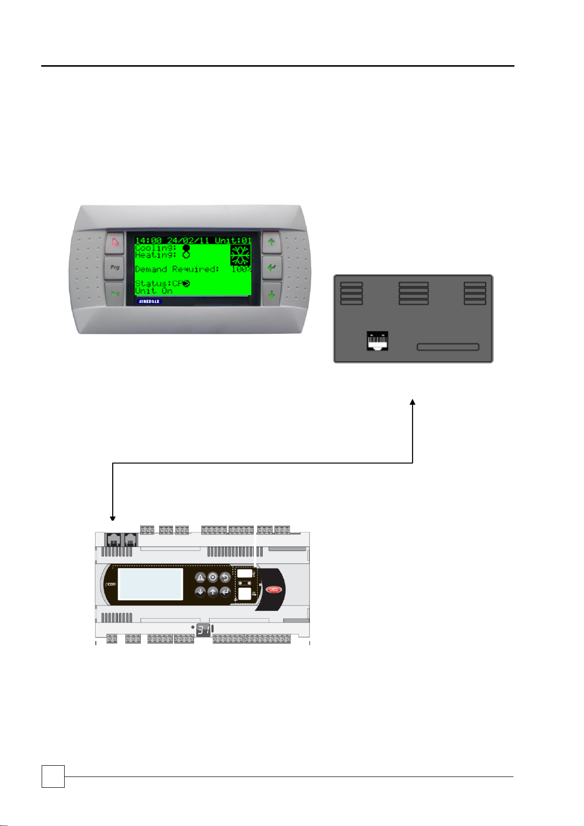
BluCube™
Condensing Unit
54
Condensing Units
Installation and Maintenance Manual : 7222094 11/2013
Local network
connection, plug
cable into J10 on
PC0 Controller
pGD1 Display
Display Keypad
RJ11
Cable
Controls
Display Keypad
Display Keypad Connections
The display keypad is equipped with an LCD display (8 rows x 22 columns) with 6 buttons, connected to the controller by
an RJ11 cable.

Condensing Units
BluCube™
Condensing Units
55
Installation and Maintenance Manual 7222094: 11/2013
Built-in
Display
Remote
Display
Function
Description
1. ALARM
When one or more alarms are active the ALARM button will illuminate red.
Pressing the ALARM button once will indicate information regarding any active alarms.
Pressing the ALARM button twice will reset any active manual-reset alarms.
Prg
2. PRG
Pressing the PRG button will select the main navigation menu.
Esc
3. ESC
Pressing the ESC button will return the user to the main display screen showing unit status.
4. UP
Pressing the UP button can either:
Scroll through the various display screens, providing the cursor is in the top left position.
Increase the value of a set point adjustment.
5. ENTER
Pressing the ENTER button will confirm any set point adjustments and move the cursor to
the next available set point.
6. DOWN
Pressing the DOWN button can either:
Scroll through the various display screens, providing the cursor is in the top left position.
Decrease the value of a set point adjustment.
Built-in Display
Remote Display
Key
Combinations
Description
+ +
.+.
.+.
UP + DOWN+
ENTER
Allows access to controller address.
+
+
ALARM +
ENTER
Allows access to controller system information.
+
+
ALARM + UP
Allows access to change controller address (only when
display address is zero).
+
Esc
+
ESC +
ENTER
Allows the user to switch between the preinstalled languages.
+
Prg
+
PRG +
ENTER
Temporarily displays the address of the controller.
+
+
ENTER + UP
Change unit on remote display keypad.
1
2
3 4 5
6
1 2 3 5 4
6
Use of Display Keypad Buttons
Remote Display Keypad Built-in Keypad
Use of Extra Function Buttons

BluCube™
Condensing Unit
56
Condensing Units
Installation and Maintenance Manual : 7222094 11/2013
A. Unit On/Off
Switch on or switch off the unit.
B. Setpoints
View the user setpoints.
C. Clock/Scheduler
View the current time and date and set on/off timezones.
D. Input/Output
View the status of the controller inputs and outputs.
E. Alarm Log
View the alarm log.
F. Board Switch
Change the controller pLAN board address.
G. Service
View maintenance related parameters, such as hours run, sensor calibration
and manual overrides.
H. Manufacturer
Manufacturer menu and adjustment of various manufacturer related parameters,
such as unit configuration and timing settings.
SERVICE SETTINGS
}
4648
CLOCK/SCHEDULER
SETPOINTS
MANUFACTURER
See Airedale
Navigation
The following instructions refer to the built-in display keypad buttons. See the table above for the corresponding buttons if
using the remote keypad.
Initially, use the button to access the main navigation menu. The first menu UNIT ON/OFF will be selected.
Use the or buttons to move to the desired menu. The selected menu will be highlighted with a black bar.
Press to enter the selected menu.
Navigation Sub Menus
There are eight sub menus available from the main navigation menu, these are listed below:
Password Protection
To guard against unauthorised adjustments, a password is required to gain access to certain menus. The passwords for
the sub menus are defined as follows:
When a password is requested use the or keys to enter the number and to access the page.
Adjusting Customer Control Settings
Use the correct keys to access the parameters to be adjusted (refer to Parameters List and Factory Values).
After entering the correct password the cursor will appear at the top left corner (Home location).
Use the or keys to move to the desired menu.
To move the flashing cursor to the required adjustable fields press and the or keys to change the values.
Press the key to move the cursor to the next field or Home location.
When the cursor is Home either use the or keys to scroll to the next sub-menu or the key to exit and
return to the Main Menu page.

Condensing Units
BluCube™
Condensing Units
57
Installation and Maintenance Manual 7222094: 11/2013
Network Display
The user will be able to view all modules connected to the AIRELAN.
By pressing + buttons, you can access each controller connected to the AIRELAN.
The display will show the unit number it is currently viewing at the top right-hand corner of the screen. (Examples
All the controllers connected to the AIRELAN network are identified using their own individual address. If duplicate
addresses are used the network will not work.
Addressing the Display Keypad
The address of the display keypad can be configured only after having connected the power supply, using the RJ11
connection cable.
To access the configuration mode, press the + + buttons simultaneously and hold them for at least 5
seconds; the screen shown above will be displayed, with the cursor flashing in the top left corner.
To change the address of the display keypad (display address setting), press the button once.
The cursor will move to the address field ().
Use the or buttons to select the desired value, and press again to confirm. The display below confirms
that the address has been successfully changed.
Note: If the field “” is set to , the terminal will communicate with the pCO board using “point-to-point” protocol (not
pLAN). The field “I/O Board address: xx” will not be displayed, as this is not used with P2P protocol.

BluCube™
Condensing Unit
58
Condensing Units
Installation and Maintenance Manual : 7222094 11/2013
Controller
Address 1
BluCube EEV
Driver
Address 9
Airedale REEV
Driver
Address 17
Remote Display
Address 32
Addressing the pCO Controller
The address of the controller can be configured by setting the display keypad to address 0 (zero).
To change the address of the pCO controller, press and hold the + buttons together and switch on the
controller. After the self test screen has been displayed, the pLAN address screen will be displayed.
The board address can also be changed be selecting Board Switch from the main menu:
The following screen will be displayed:
The unit number can be changed to another number on the network.

Condensing Units
BluCube™
Condensing Units
59
Installation and Maintenance Manual 7222094: 11/2013
max 50 m
Ferrite
Note: If using a shielded cable, it can be located at a maximum distance of 200 m
Remote Display Keypad
Remote installation requires the insertion of 1 ferrite (part number 6171433) as illustrated below. The ferrite is illustrated
in both the open and closed position. The ferrite is mounted on the telephone connecting cable, on the controller side.
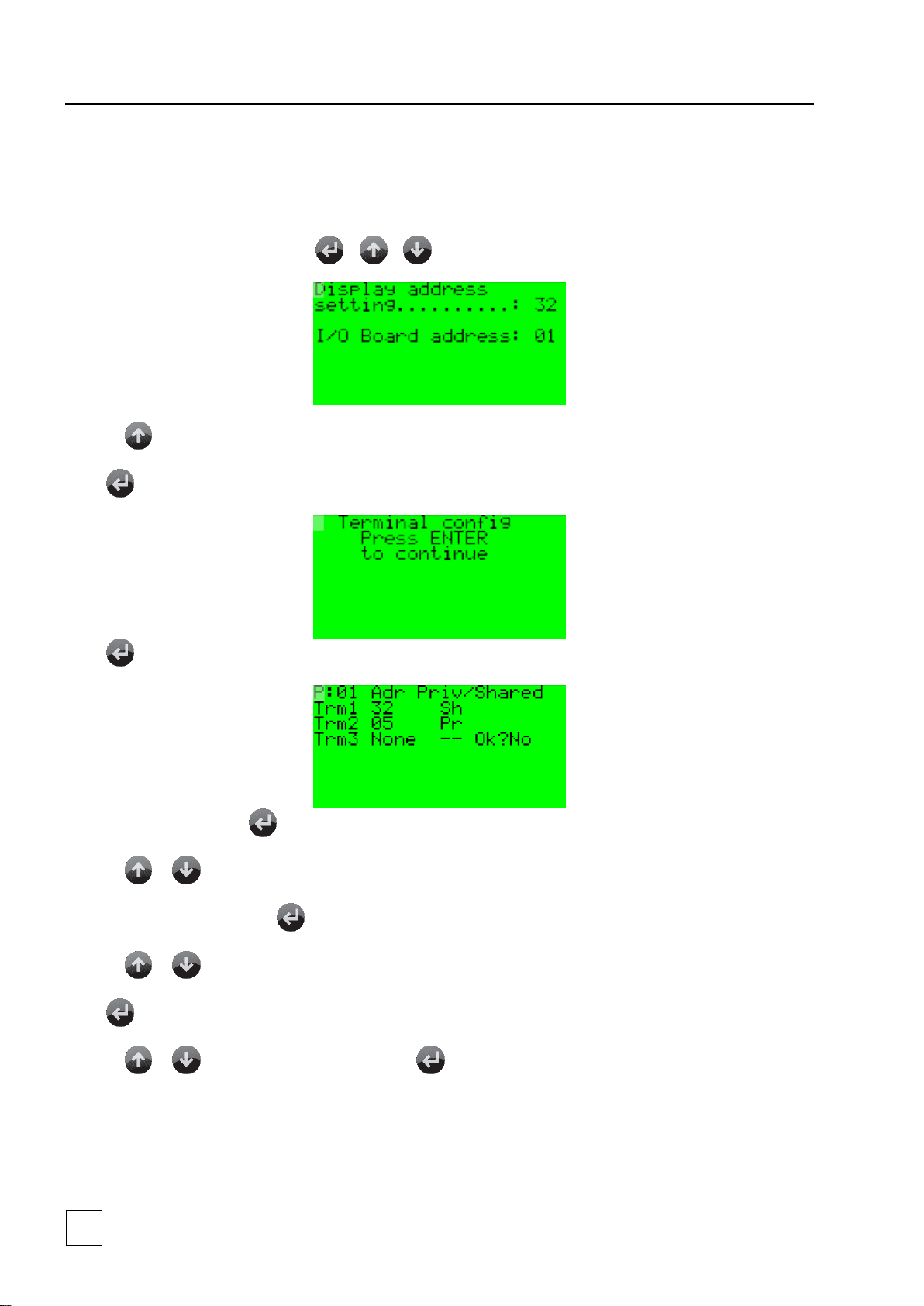
BluCube™
Condensing Unit
60
Condensing Units
Installation and Maintenance Manual : 7222094 11/2013
Programming the Remote Display Keypad to the Controller
In the situation that the terminal display address is required to be set up, the following procedure applies.
Set the correct address on the display, connect to the controller and then power up the unit.
By simultaneously pressing and holding + + , the display will show the Display Address screen.
Pressing will change the I/O board address to the controller address 1.
Press . The following screen will be displayed:
Press again. The display will show the following terminal configuration screen:
Selecting Terminal 1 – Press until the cursor is underneath
Pressing or will change the 00 to the required value 32.
Setting Private to Shared – Press until the cursor is underneath the Pr (PRIVATE) symbol.
Pressing or will change the to (SHARED) symbol.
Press until the cursor is underneath the NO.
Pressing or will change the NO to YES. Press and the display is programmed.

Condensing Units
BluCube™
Condensing Units
61
Installation and Maintenance Manual 7222094: 11/2013
Addressing the pCO5 Controller
The address of the controller can be configured by setting the display keypad to address 0 (zero).
To change the address of the pCO5 controller, press and hold the + buttons together and switch on the
controller.
After the self test screen has been displayed, the pLAN address screen will be displayed.

BluCube™
Condensing Unit
62
Condensing Units
Installation and Maintenance Manual : 7222094 11/2013
Solid
Unit On
Unit Off
Alarm
Flashing
Compressor
on by timing
Compressor
off by timing
Cooling
Heating
Defrosting
Alarm
Pump
down
Reversing
Valve
Cooling
Heating
Cooling
Heating
Cooling
Heating
Cooling
Heating /
Cooling /
Heating
Solid
Unit Off
Cooling
Heating
Flashing
Cooling while
compressor is on
by timing –
preparing to go
into heating
Heating while
compressor is on
by timing –
preparing to go
into cooling
BluCube Operational Icons
Below are the icons which are present on the PGD1 display once the unit is running in the relevant operation mode.
Compressor
Unit Status
Cooling/Heating Indication

Condensing Units
BluCube™
Condensing Units
63
Installation and Maintenance Manual 7222094: 11/2013
-
Use Awg20/22 twisted pair (with overall
shield) cable, Belden ref. 8762 (Airedale
ref: 6110316), or equivalent, for
network
Network Connections (Inward
connection)
+
GND
-
Use Awg20/22 twisted pair (with overall
shield) cable, Belden ref. 8762 (Airedale
ref: 6110316), or equivalent, for
network
Network Connections (Outward
connection)
+
GND
-
Use Awg20/22 twisted pair (with overall
shield) cable, Belden ref. 8762 (Airedale
ref: 6110316), or equivalent, for
network
Network Connections (Inward
connection)
+
GND
-
Use Awg20/22 twisted pair (with overall
shield) cable, Belden ref. 8762 (Airedale
ref: 6110316), or equivalent, for
network
Network Connections (Outward
connection)
+
GND
RX+/Tx-
Use Awg20/22 twisted pair (with overall
shield) cable, Belden ref. 8762 (Airedale
ref: 6110316), or equivalent, for
network
Network Connections (Inward
connection)
RX+/Tx+
GND
RX-/Tx-
Use Awg20/22 twisted pair (with overall
shield) cable, Belden ref. 8762 (Airedale
ref: 6110316), or equivalent, for
network
Network Connections (Outward
connection)
RX+/Tx+
GND
Network Wiring
Carel RS485
pLAN
Notes for Installing pLAN:
Pay attention to the network polarity - RX/TX+ on one board must be connected to RX/TX+ on the other boards. The
same is true for RX/TX- . The shield twisted pair must be connected to ground at both ends.
Use AWG20/22 Twisted Pair (With Overall Shield), Cable Belden Ref. 8762, (Airedale Ref: - 6110316) For pLAN
Network.
Modbus

BluCube™
Condensing Unit
64
Condensing Units
Installation and Maintenance Manual : 7222094 11/2013
GENERAL
The following commissioning information is based on a complete matched Airedale
system using R410A refrigerant.
Pre-Start Checks
Once the whole system has been installed it is most important that the following pre-start
checks are made:-
GENERAL
1 The unit condition is satisfactory.
2 All pipework is complete and insulated where necessary.
Electrical
1 All electrical connections (both mains and control) are properly terminated.
2 The power supply is of the correct voltage and frequency.
3 External fuses/circuit breakers are of the correct rating.
4 The units are properly earthed in accordance with current regulations.
5 All pipework is earth bonded as required.
6 Check that there is a supply to the crankcase heater (if fitted) and ensure this is
switched on for a minimum of 8 hours prior to the unit operation.
Refrigeration
1 The unit condition is satisfactory.
2 All pipework is complete and insulated where necessary.
3 All fans are able to rotate freely.
4 The system has been evacuated correctly.
5 Check the operation of the high and low pressure switch settings. These should be
as follows:-
HIGH PRESSURE SWITCH - 40.25 Bar CUT OUT
LOW PRESSURE SWITCH - 0.5 Bar - CUT OUT
2.5 Bar - CUT IN
6 The low pressure switch is automatically reset. The high pressure switch must be
reset by either switching the unit off/on at the isolator, or de-energising the
compressor signal from the indoor unit.
Fan Speed / head
pressure control
The head pressure control, allows control to be achieved in ambients down to -20°C.
Defrost Control
Defrost is controlled by software (user defined) via a coil temperature sensor.
Commissioning

Condensing Units
BluCube™
Condensing Units
65
Installation and Maintenance Manual 7222094: 11/2013
Control Circuit Checks
Please refer to the Airedale matched indoor unit manual for further details.
Cooling Only & Heat Pump
1. Disconnect the compressor power wiring from the compressor contactor. Switch
on mains power.
2. Check status of the Alarm output on the microprocessor, refer to information
provided with unit.
3. Select Cooling mode on the indoor unit and check for continuity between the
cooling signal on the microprocessor.
4. The compressor contactor should pull in.
5. De-select Cooling mode on the indoor unit and check for no continuity between
the cooling signal on the microprocessor.
6. The compressor should switch off.
Heat Pump Units
Follow steps 1-6 above and then check heating operation as described below:
1. Select heating mode on the indoor unit and check for continuity between the
heating signal and the microprocessor.
2. Check status of the microprocessor; refer to information provided with unit.
3. The compressor contactor should pull in.
4. The compressor should switch on. The reversing valve should activate changing
the unit from cooling to heating mode. Refrigerant may travel to different parts of
the system (it may produce a whoosh noise when this occurs; this is normal)
when the valve is activated.
5. De-select heating mode on the indoor unit and check for no continuity between
the heating signal and the microprocessor. (the reversing valve will again
change positions)
6. The compressor contactor should drop out.
7. Switch off mains power and reconnect compressor power wiring.
Commissioning

BluCube™
Condensing Unit
66
Condensing Units
Installation and Maintenance Manual : 7222094 11/2013
Refrigerant Charging
The following information is based on a complete Airedale matched system and indicates
the approximate amount of refrigerant charge required. It is also assumed that the system
has been designed within operating parameters and to good refrigeration practice.
NOTE: It is important that the system is charged with the correct amount of
refrigerant. Remember, a seriously over or undercharged system may lead to major
component failure.
The final refrigerant charge level should be set by the design evaporating and condensing
pressures, together with a full or nearly full sight glass.
The suction and discharge pressures should be constantly monitored whilst charging is
in progress.
NOTE:- The sight glass level must be checked in the COOLING MODE ONLY.
Adding Oil
The initial oil charge in the compressor is suitable for pipe runs up to 20m
(equivalent length).
For longer pipe runs add 26 g of oil for every ADDITIONAL 0.45 kg of refrigerant added
up to the maximum permissible equivalent pipe runs stated. Please consult Airedale for
further details.
Commissioning

Condensing Units
BluCube™
Condensing Units
67
Installation and Maintenance Manual 7222094: 11/2013
SYSTEM READINGS
NOTE :- The sight glass should only be used as an assistance to charging as the
charge level showing in the glass will vary according to different operating
conditions. This is especially noticeable with the heat pump units where the
system may appear to be undercharged in the heating mode.
Evaporating temperature (suction gauge) should read approximately 2°C. to 3°C. with a
room (return air temperature) of approximately 22 °C.
Condensing temperature (as read on the discharge gauge) should be in the region of 45
to 46 °C. with an external ambient temperature of 30°C (Condensing is normally 15 °C.
above ambient).
Running Checks
Once the system has been charged, the following running checks should be carried out:-
Check the operation of the fan speed controller by observing an increase in fan speed if
the outdoor coil is temporarily partially blocked.
If the system is a heat pump option, check that the reversing valve switches over from
cooling to heating and vice-versa.
NOTE: Head pressure control also operates in heating mode by slowing down the
outdoor unit fan as the system pressure rises. This can be checked by partially
blocking the inlet grilles of the indoor unit and observing the outdoor unit fan
slowing down.
IMPORTANT
FINALLY AND MOST IMPORTANTLY - Fill in the commissioning sheet and return a
copy to the factory to ensure that the warranty on the unit will be valid.
Commissioning

BluCube™
Condensing Unit
68
Condensing Units
Installation and Maintenance Manual : 7222094 11/2013
FAULT
POSSIBLE CAUSE
REMEDY/ACTION
CRITICAL ALARMS:
Aux. Alarm
Auxiliary Trip.
Check operation of customer-added
alarm function.
Outdoor Fan Fault
Fan Trip.
Check and (if necessary) replace fan.
Coil Sensor Fault
Faulty Sensor.
Replace sensor.
No Cooling/Heating
Compressor Protection Delay.
Wait for a maximum of 10 minutes then
re-check.
Unit Will Not Start
No power.
Check power supply to the controller.
Wired incorrectly.
Check wire connections in accordance with
wiring diagram on control box lid.
Loose wires.
Check all wires, connections, terminals etc.
Compressor not operating
No power to compressor.
Check isolator, fuses, MCBs, contactor and
control circuit wiring.
Low pressure switch operated (if
fitted) (large or complete loss of
refrigerant charge).
Repair leak and recharge system - if
completely out evacuate before charging.
Condenser fan thermal trip open
circuit.
Investigate and correct.
Seized compressor.
Replace compressor - investigate oil
trapping and general installation.
Defective compressor motor.
Check winding resistances - replace
compressor. If burnt out follow burn out
procedure using suction line burn-out drier.
Noisy Compressor
Expansion valve malfunction
(abnormally cold suction Iine).
Ensure sensor is tight on suction and
superheat is correct (normally 5 to 6°C).
Replace power assembly or valve
as necessary.
Lack of oil.
Repair leaks if any, add oil if required but not
too much. Investigate pipe system and
trapping. If no oil still, drain compressor and
measure in correct quantity.
Broken or damaged compressor valve
reed (compressor knocking).
Replace compressor (possible other
symptom is that it will have high suction
pressure).
Worn or scored compressor bearing.
(excessive knocking).
Replace compressor.
Head Pressure too high/HP cutout operated
Condenser coil clogged or dirty.
Clean condenser.
Overcharge of refrigerant. Normally
troublesome in warm weather.
Remove excess refrigerant from system.
Air or other non-condensable gas
in system.
Evacuate system and re-charge with new
refrigerant.
Head pressure controller faulty.
Check fan speed controller - if
faulty - replace.
Fan not operating or operating
inefficiently.
Check motor - if faulty - replace.
Head pressure too low
Fan operating too fast in low
ambient conditions.
Check fan speed controller adjustment - if
faulty - replace.
Troubleshooting

Condensing Units
BluCube™
Condensing Units
69
Installation and Maintenance Manual 7222094: 11/2013
FAULT
POSSIBLE CAUSE
REMEDY / ACTION
Compressor short cycles or
LP cut-out operated
LP switch faulty (if fitted).
Check cut out pressure and replace
if necessary.
Dirty indoor unit filters.
Replace.
Dirty or icing evaporator (reduced airflow).
Defrost and/or clean. Check gas charge and
expansion valve.
Lack of refrigerant (bubbles in sight glass
only as indication).
Check for leaks - repair and
recharge system.
Clogged filter drier (pressure/temperature
drop across it).
Replace.
Condenser fan running at full speed in
winter (full airflow).
Check fan speed controller setting - if
faulty - replace.
Start up problems in very low ambients or
when long pipe runs are experienced.
Check for low suction pressures on start-up
and fit a low ambient start kit if required, or
check operation of system if already fitted.
Suction Pressure too low
Low evaporator airflow.
Check fan motors, belts and drives.
Flash gas (bubbles in sight glass) at
expansion valve.
Investigate for refrigerant leaks, repair and
re-charge system.
Clogged filter drier (pressure / temperature
drop across it).
Replace.
Obstruction in liquid line solenoid valve.
Inspect, clean or replace.
Obstruction in expansion valve.
Inspect, clean or replace.
Defrost cycle not initiating
Unit set for cooling only.
Check links.
Check unit configuration / defrost settings
Condenser fan not operating
- power on
Power supply failure.
Check power supply at circuit breaker.
Wiring to motor.
Check voltage at motor terminals.
Motor / fan assembly jammed.
Isolate unit and check free rotation of
motor/fan assembly. If faulty - replace.
Motor internal overheat protector tripped.
Carry out continuity check at terminals “TK”
in motor terminal box. If tripped and motor
hot - check bearings. If tripped and motor
cold - replace motor.
Faulty motor windings/capacitor.
Motor humming would indicate fault in motor
or capacitor. Check windings for continuity
and if OK replace capacitor.
Minimum speed set too low.
Adjust head pressure controller to suit.
Faulty pressure sensor.
Check electrical connections are secure at
controller and pressure sensor. Replace
controller and sensor (as they are
matched sets).
Faulty Fan Speed Controller.
Link wires “line” and “load” to bypass
controller. If motor runs full speed replace unit.
Troubleshooting

BluCube™
Condensing Unit
70
Condensing Units
Installation and Maintenance Manual : 7222094 11/2013
FAULT
POSSIBLE CAUSE
REMEDY / ACTION
Condenser fan runs too fast
High ambient condition or excessive recirculation of air around condenser coil.
Check installation against design.
Minimum set speed setting incorrect.
Adjust as necessary.
Incorrect pressure sensor setting.
Adjust sensor screw as necessary.
Faulty Fan Speed Controller.
Replace controller and sensor (as they are
matched sets).
Faulty pressure sensor.
Replace controller and sensor (as they are
matched sets).
Condenser fans runs only
slowly
Incorrect pressure setting.
Adjust sensor screw as necessary.
Faulty Controller.
Replace controller and sensor (as they are
matched sets).
Faulty Pressure sensor.
Replace controller and sensor (as they are
matched sets).
Motor/capacitor faulty.
Replace.
Troubleshooting

Condensing Units
BluCube™
Condensing Units
71
Installation and Maintenance Manual 7222094: 11/2013
Item
Task
Frequency
Unit Inspection
6 Mths
12 Mths
60 Mths
General Inspections
Check for visible mechanical damage to unit.
Check for cleanliness.
Visually inspect the unit for general wear and tear, treat
metalwork.
Rust should be inhibited, primed and touched up with matching paint.
Check for excess vibration from other rotating equipment.
Coil Guard Cleaning
Ensure that the coil guard is free from debris.
Electrical Inspection
Check main power supply voltages.
Check electrical terminals are tight.
Check that the control panel and fan assembly cables are
securely fastened together.
Check amperages are as per design.
Controls Alarm Log
Check alarm log for any spurious events.
Service tools / Test Equipment
Multimeter
Screwdrivers/ Allen keys
Safety Equipment
Safety Glasses/ Goggles
Operational Maintenance Checks
Owners Responsibility
To ensure that the unit can be maintained correctly the following requirements are required.
Maintain a safe working environment around the unit, free from obstructions and debris.
The unit shall follow the following maintenance regime as a minimum.
The equipment contains live electrical and moving parts, ISOLATE prior to maintenance or repair work.
Ensure Lock off procedures is carried out accordingly.
Maintenance Schedule

BluCube™
Condensing Unit
72
Condensing Units
Installation and Maintenance Manual : 7222094 11/2013

Condensing Units
BluCube™
Condensing Units
73
Installation and Maintenance Manual 7222094: 11/2013
Head Office:
Airedale International Air Conditioning Ltd
Leeds Road
Rawdon
Leeds LS19 6JY
United Kingdom
Tel:
+44 (0) 113 239 1000
Fax:
+44 (0) 113 250 7219
e-mail:
enquiries@airedale.com
website:
www.airedale.com
V1.0.0
09/2011
V1.1.0
02 / 2012
V1.2.0
09/2012
V1.3.0
02/2013
V1.4.0
11_2013
 Loading...