

Page 1
Smart Ride
Smart Ride
COMPLETE DIGITAL AIR MANAGEMENT SYSTEM
COMPLETE DIGITAL AIR MANAGEMENT SYSTEM
Installation and operating
Installation and operating
instructions
instructions
Index
LCD Controller and Relay Control Box Layouts
Plug n Play Installation
Non-Plug n Play Installation
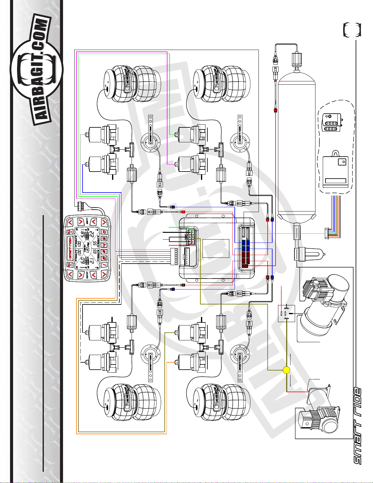
Non-Plug n Play Schematic
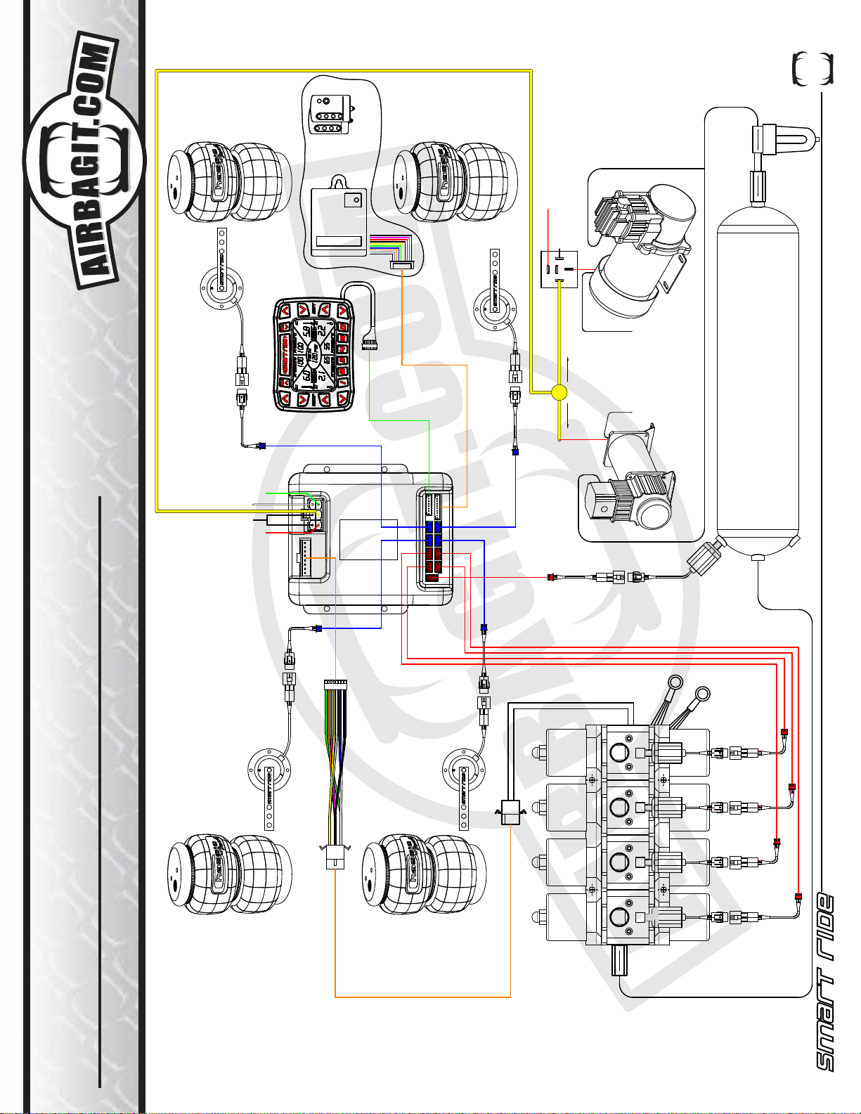
Air-Engine / Air Force Wiring Schematics
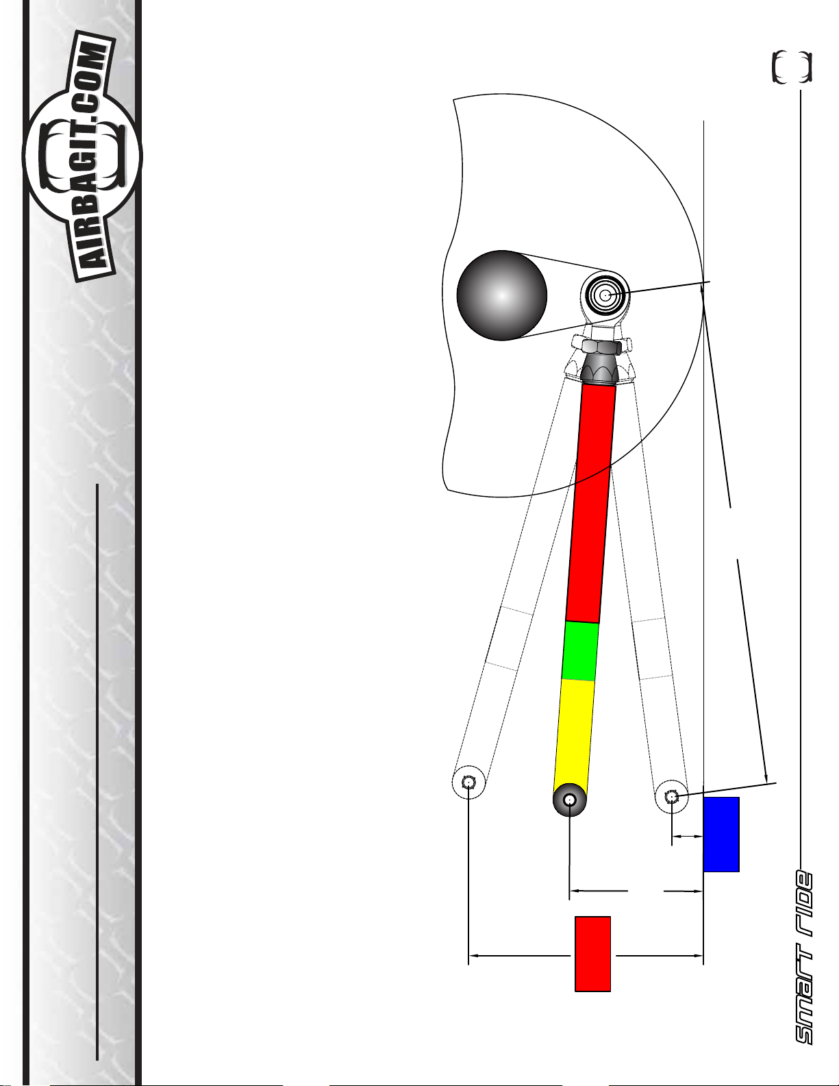
Height Sensor Installation
Preset and Compressor Setup and Functionality Tips (Setup Screen #1)
Timing, Pressure Switch and Tolerance Setup (Setup Screen #2)
Height Sensor Calibration (Setup Screen #3 and #4)
Optional Input Wiring Schematic
The System Includes
Smart-Ride Standard
LCD Controller
Relay Control Box
Page
1
2
3
4
5
6-8
9
10
11
12
QTY
1
1
Power Loom
Valve Loom
Smart-Ride P and Smart-Ride HP
300 PSI Digital Pressure Sender w/18” Loom (Optional 240” Loom)
Spanner Wrench
Smart-Ride H and Smart-Ride HP
Height Sensors w/240” Looms
Smart-Ride HP Hardware Pack
Ball Joints
1/4-28 x 12” Threaded Rod
1/4-28 Hex Nuts
1/4-28 Nyloc Nuts
A I R B A G I T. C O M S U S P E N S I O N S
2 6 0 S . H I B B E R T , M E S A , A Z P H . 8 0 0 - 8 4 2 - 8 7 8 9
1
1
5
1
4
1
8
4
8
8
Page 2
Smart Ride
Smart Ride
COMPLETE DIGITAL AIR MANAGEMENT SYSTEM
COMPLETE DIGITAL AIR MANAGEMENT SYSTEM
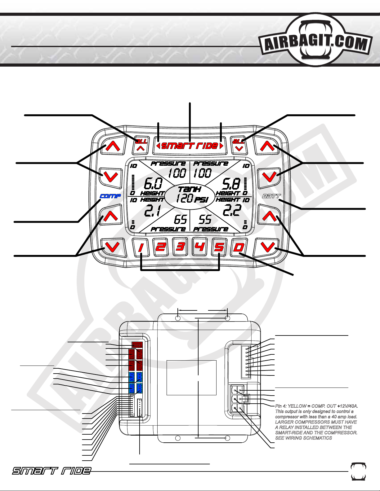
LCD CONTROLLER
LCD CONTROLLER
SMART-RIDE BUTTON
INFLATE ALL
FOUR AIR BAGS
SCROLL LEFT
THROUGH SETUP
Enter into setup screens
SCREEN
SCROLL RIGHT
THROUGH SETUP
SCREEN
DEFLATE ALL
FOUR AIR BAGS
FRONT
LEFT MANUAL
CONTROL
COMPRESSOR
INDICATOR
BLUE = RUNNING
GREEN = IDLE
RED = ALARM
COMPRESSOR RAN FOR
MORE THAN 5 MINS.
REAR
LEFT MANUAL
CONTROL
5 USER PRESETS
Single Press will display Preset Levels
Double Press will activate the Preset
RELAY CONTROL
RELAY CONTROL
BOX
BOX
PRESSURE
SENDER
(RED)
HEIGHT
SENSORS
(BLUE)
LEFT REAR
LEFT FRONT
RIGHT REAR
RIGHT FRONT
RIGHT FRONT
TANK
LEFT FRONT
LEFT REAR
RIGHT REAR
OPTIONAL INPUTS
+12V
PRESET 1 = BLACK
PRESET 2 = BROWN
PRESET 3 = RED
PRESET 4 = ORANGE
PRESET 5 = YELLOW
FRONT UP = GREEN
FRONT DOWN = BLUE
REAR UP = PURPLE
REAR DOWN = GRAY
COMPRESSOR = WHITE
LCD CONTROLLER
4.76
1.97
FRONT
RIGHT MANUAL
CONTROL
LOW BATTERY
INDICATOR
BLUE = RUNNING
GREEN = IDLE
RED = ALARM
REAR
RIGHT MANUAL
CONTROL
MANUAL
COMPRESSOR
ACTIVATION
VALVE LOOM
BLACK = FRONT LEFT UP
WHITE = FRONT LEFT DOWN
BLUE = FRONT RIGHT UP
GREY = FRONT RIGHT DOWN
YELLOW = REAR LEFT UP
BROWN = REAR LEFT DOWN
PURPLE = REAR RIGHT UP
GREEN = REAR RIGHT DOWN
12
4
3
5
6
POWER LOOM
Pin 1:BLACK = GROUND
Pin2: RED = BATTERY +12V
Pin 3: BLACK = GROUND
Pin 4: YELLOW = COMP. OUT +12V/40A.
This output is only designed to control a
compressor with less than a 40 amp load.
LARGER COMPRESSORS MUST HAVE
A RELAY INSTALLED BETWEEN THE
SMART-RIDE AND THE COMPRESSOR.
SEE WIRING SCHEMATICS
Pin 5: WHITE = IGNITION +12V
Pin 6: GREEN = COMPRESSOR
POWER +12V
A I R B A G I T. C O M S U S P E N S I O N S
2 6 0 S . H I B B E R T , M E S A , A Z P H . 8 0 0 - 8 4 2 - 8 7 8 9
2 6 0 S . H I B B E R T , M E S A , A Z P H . 8 0 0 - 8 4 2 - 8 7 8 9
A I R B A G I T. C O M S U S P E N S I O N S
1
1
Page 3
Smart Ride
Smart Ride
COMPLETE DIGITAL AIR MANAGEMENT SYSTEM
COMPLETE DIGITAL AIR MANAGEMENT SYSTEM
PlugnPlay
INSTALLation
1. Disconnect the negative battery terminal.
2. Remove top of Plug n Play by removing external screws with supplied bit.
3. Mount the Plug n Play in a dry location. It is recommended that you leave 5.5”-6” of room free in front of the PnP
for valve removal.
4. Install tank and connect a line to the tank from the compressor and a second line back to checked inlet of the
PnP.
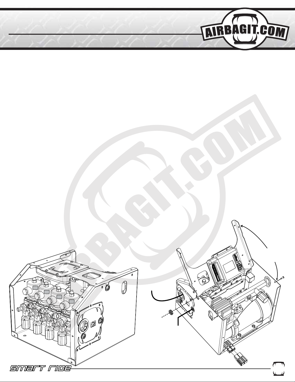
5. Route Airbag airlines through the large grommet and connect to the valves. See figure below for valve assignments.
6. Run 8 gauge power wire to the battery and connect through the supplied 60Amp brearker. Also, make sure the
ground wire is connected to a clean part of the frame.
7. Connect the Smart-Ride’s White wire to the cars ignition.
8. Locate a safe position for the LCD controller to be mounted. The controller can also remain loose and be handheld. Make sure the controller isn’t in a position where it can be accidentally activated while driving.
9. Route the LCD controller wire loom from the controller to the Plug n Play. The loom will pass through the small
plastic grommet in the middle top of the Plug n Play. Do not plug LCD loom into the Relay control box yet.
10. Plug the Red and Black power connection into the Plug n Play.
11. Connect the vehicles battery.
12. Plug the LCD Controller into the Relay control box. The LCD display will turn on the run through its intialization
process. Once the LCD turns on the compressor will start filling the tank. The display will show the tank pressure
and the individual bag pressures. The height sensor will not display until they are connected.
13. Test the valves to make sure they are connected correctly.
14. Mount the height sensors (See Height Sensor Installation Section) and route wires through the
same grommet as the LCD loom. The height display for each corner will activate when the height sensor is
connected to the relay control box.
15. (Optional) Connect necessary “Optional Input Loom” to the third party controller. +12V Only
16. Calibrate the height sensors. (See Calibration Section).
17. Reinstall Plug n Play Top.
REMOVE SCREWS AND
ROTATE TOP BRACE TO
GAIN ACCESS TO THE
SMART-RIDE RELAY
CONTROL BOX
RR
FR
RL
ROUTE AIRBAG AIRLINES
THROUGH LARGE GROMMET
FL
ROUTE HEIGHT SENSOR
LOOMS AND LCD
CONTROLLER CABLE
THROUGH GROMMET
CHECKED VALVE INLET
PLUMB TO TANK
2 6 0 S . H I B B E R T , M E S A , A Z P H . 8 0 0 - 8 4 2 - 8 7 8 9
A I R B A G I T. C O M S U S P E N S I O N S
PLUG MAIN POWER
HARNESS IN BEFORE
CONNECTING THE LCD
CONTROLLER
2
Page 4
Smart Ride
Smart Ride
COMPLETE DIGITAL AIR MANAGEMENT SYSTEM
COMPLETE DIGITAL AIR MANAGEMENT SYSTEM
non Plug n Play Installation
non plug n play installation
1. Disconnect the negative battery terminal.
2. Mount the Smart-Ride in a dry location away from hot exhaust and any moving components.
3. Determine where the LCD Controller will be mounted.
4. Connect the LCD controller to the Relay Control Box.
5. Wire according to diagram on page 1.
a.Power Loom
i. Connect the Black wires (Pin 1 & Pin 3) to (-) Ground.
ii. Connect the Red wire (Pin 2) to constant +12V.
iii. Connect the Yellow (Pin 4) to the Compressor (less than 40amp) or Compressor Relay
(over 40amp draw).
1.This output is only designed to supply power to a compressor that requires less than
40 amps. Larger compressors must have a relay installed in between the Smart-Ride
and the Compressor. (Wiring Schematics)`
iv. Connect the White wire (Pin 5)to an Ignition wire. This wire will turn the LCD Controller
On. When the ignition turns on it will also activate Preset #1 if that option has been turned on
(See Screen #2 instructions for details).
v. Connect the Green Wire to constant +12V (Pin 6). This wire will supply power to the inter nal relay that powers the Yellow Wire.
b.Valve Loom
i. Connect each wire to its corresponding valve as shown on the Non-PnP Wiring Schematic.
ii. If you have purchased this Smart-Ride controller with one of Airbagit.com's Air Engine
valve assemblies, or Air Force then the Valve Loom will plug right into the Air Engine's white 9
pin plug. See Air Engine Wiring Schematic.
The system will now have control of the valves but will not display pressures or heights until
the sensors are installed.
c. Pressure Sending units (RED). (SMART-RIDE P and SMART-RIDE HP Models Only)
After the each Pressure Sending unit is installed you will see the tank pressure displayed on the
LCD Controller.
i. Install the pressure sending units and plug into the red sockets on the relay control box as
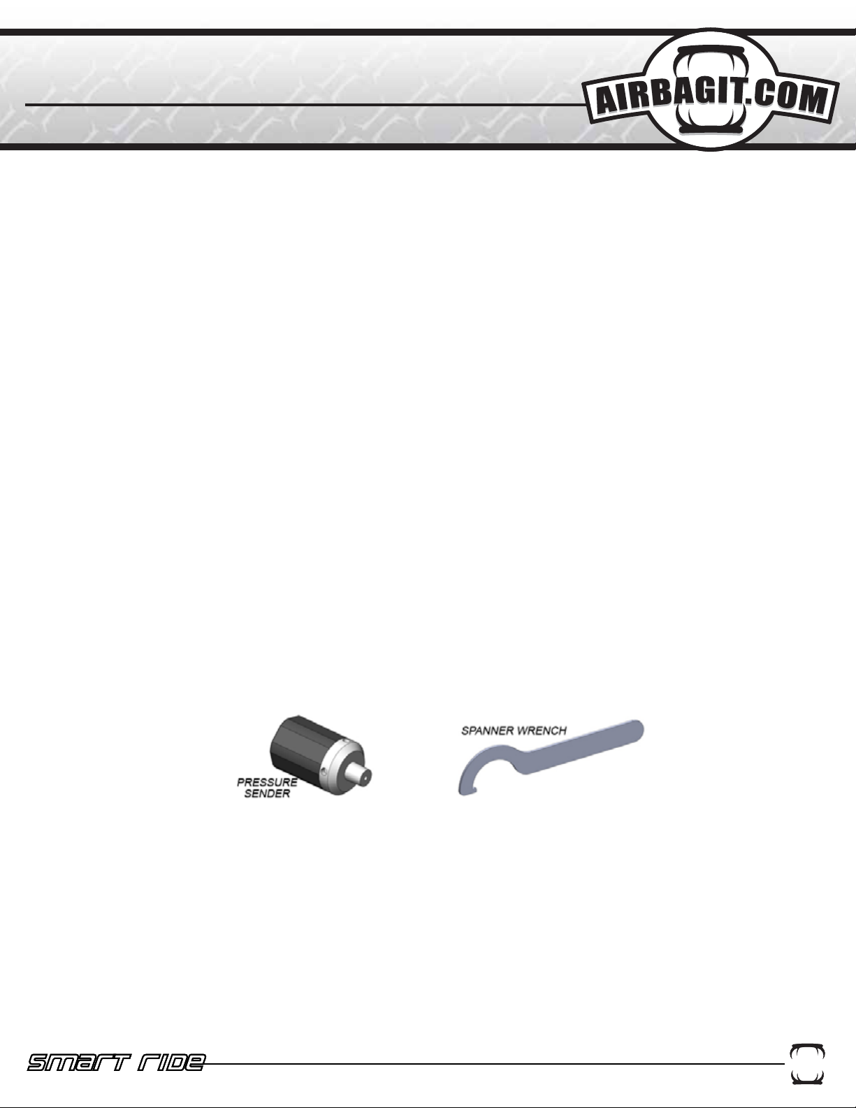
indicated on page 1. Note: Pressure Sending units are to be tightened with the included
spanner wrench only, Tightening by hand will damage the sending unit.
ii. Smart-Ride P Models with speed control adjusters will need to make sure that the pres
sure sender is installed between the bag and the speed control adjuster. Installing the pres
sure sender after the speed control valve will cause inaccurate readings thus affecting the
units ability to reach its preset values.
d. Height Sensors (BLUE). (SMART-RIDE H and SMART-RIDE HP Models Only)
i. SEE HEIGHT SENSOR INSTALLATION INSTRUCTIONS
e. Optional Inputs (These should be installed after the system has been completely installed and
setup)
i. NOTE: THESE ARE ONLY TO BE CONNECTED IF YOU INTEND ON USING A THIRD
PARTY CONTROLLER I.E. 12 CHANNEL REMOTE, OR ALARM SYSTEM. If you do not
intend on controlling the Smart-Ride with anything other than the Smart-Ride LCD Controller
then leave this loom unplugged.
ii. In order to use the optional third party inputs you will need to supply each wire with +12V.
This is not a constant +12V but momentary power that is supplied by a third party controller.
A I R B A G I T. C O M S U S P E N S I O N S
2 6 0 S . H I B B E R T , M E S A , A Z P H . 8 0 0 - 8 4 2 - 8 7 8 9
2 6 0 S . H I B B E R T , M E S A , A Z P H . 8 0 0 - 8 4 2 - 8 7 8 9
A I R B A G I T. C O M S U S P E N S I O N S
3
Page 5
RIGHT
FRONT
VALVE
DUMP
HEIGHT
SENSOR
REAR
RIGHT
VALVE
DUMP
HEIGHT
SENSOR
MAX
300 PSI
SENDER
PRESSURE
TO VIEW A COLOR VERSION PLEASE VISIT AIRBAGIT.COM
OPTIONAL
THIRD
PARTY
CONTROLLER
12 CH.
REMOTE
4
FILL
FILL
VALVE
VALVE
TANK
LCD CONTROLLER
TANK
300 PSI
SENDER
PRESSURE
300 PSI
SENDER
PRESSURE
BATTERY +12V
IGNITION
GROUND
BATTERY +12V
FILL
FILL
VALVE
300 PSI
SENDER
PRESSURE
6
5
3
4
12
BOX
RELAY
CONTROL
TANK TANK
300 PSI
SENDER
VALVE
PRESSURE
OPTIONAL
60 AMP
+12V WITH
BATTERY
GROUND
85
87A
87
86
WATER
TRAP
FUSE
30
VALVE
CHECK
A I R B A G I T. C O M S U S P E N S I O N S
2 6 0 S . H I B B E R T , M E S A , A Z P H . 8 0 0 - 8 4 2 - 8 7 8 9
MAX MAX
VALVE
DUMP
HEIGHT
SENSOR
LEFT
FRONT
Smart Ride
COMPLETE DIGITAL AIR MANAGEMENT SYSTEM
VALVE
DUMP
LEFT
REAR
MAX
HEIGHT
SENSOR
WITH MORE
THAN 40AMP DRAW
COMPRESSOR
RELAY REQUIRED
OR
GROUND GROUND
WITH LESS
40AMP DRAW
THAN A
COMPRESSOR
NO RELAY
REQUIRED
SYSTEMS
NON-PLUG N PLAY
Page 6
TO VIEW A COLOR VERSION PLEASE VISIT AIRBAGIT.COM
5
RIGHTLEFT
FRONT
HEIGHT
SENSOR
MAX
IGNITION
GROUND
12 CH.
REMOTE
THIRD
PARTY
OPTIONAL
CONTROLLER
BATTERY +12V
56
4
3
BATTERY +12V
12
REAR
RIGHT
HEIGHT
SENSOR
MAX
TRAP
WATER
OPTIONAL
VALVE
CHECK
WITH
60 AMP
FUSE
BATTERY
+12V
GROUND
85
87A
30
87
86
COMPRESSOR
WITH MORE
THAN 40AMP DRAW
RELAY REQUIRED
OR
GROUND GROUND
40AMP DRAW
COMPRESSOR
WITH LESS
THAN A
NO RELAY
REQUIRED
FRONT
MAX
HEIGHT
SENSOR
REAR
LEFT
MAX
HEIGHT
SENSOR
A I R B A G I T. C O M S U S P E N S I O N S
GROUND
FL
RL
FR
RR
DOWN
DOWN
DOWN
DOWN
SENDER
300 PSI
PRESSURE
SENDER
300 PSI
PRESSURE
SENDER
300 PSI
PRESSURE
SENDER
300 PSI
PRESSURE
FL
UP
RL
UP
FR
UP
RR
UP
VALVE
CHECK
2 6 0 S . H I B B E R T , M E S A , A Z P H . 8 0 0 - 8 4 2 - 8 7 8 9
wiring schematics
air engine Or air force
Smart Ride
COMPLETE DIGITAL AIR MANAGEMENT SYSTEM
Page 7
WHEEL
AXLE
6
GROUND
HEIGHT SENSOR INSTALLATION
HEIGHT SENSOR INSTALLATION
MID TRAVEL
“VL/2”
ARM
LENGTH
“B”
LOWEST
“AL”
A I R B A G I T. C O M S U S P E N S I O N S
2 6 0 S . H I B B E R T , M E S A , A Z P H . 8 0 0 - 8 4 2 - 8 7 8 9
1. MEASURE THE SUSPENSION TRAVEL WITH YOUR AIR SYSTEM.
a. DETERMINE WHICH SUSPENSION LINK IS GOING TO BE ATTACHED TO THE HEIGHT SENSOR
b. INFLATE THE SUSPENSION TO MAXIMUM PRESSURE OR MAXIMUM LIFT.
c. MEASURE THE DISTANCE FROM THE FRAME SIDE LINK PIVOT POINT OF THE LINK TO THE GROUND.
d. WRITE DOWN THIS MEASUREMENT IN BOX "A".
e. DEFLATE THE SUSPENSION TO ITS LOWEST POINT.
f. MEASURE THE DISTANCE FROM THE SAME PIVOT POINT TO THE GROUND. WRITE DOWN THIS MEASUREMENT IN BOX
"B".
g. SUBTRACT “A” AND “B” TO GET THE VERTICLE LIFT. WRITE THIS DOWN IN BOX "VL".
h. RAISE THE VEHICLE HALF WAY UP SO THAT THE FRAME SIDE PIVOT IS EQUAL TO HALF OF "VL".
Smart Ride
COMPLETE DIGITAL AIR MANAGEMENT SYSTEM
i. MEASURE THE DISTANCE BETWEEN THE PIVOT BOLTS ON THE LINK AND WRITE THIS DOWN IN BOX "AL".
“A”
MAX LIFT
Page 8

MAX.
DISTANCE
MOUNTING
"AL"
7
4.50
3.76
3.02
"VL"
4.25
MIN.
DISTANCE
MOUNTING
"AL"
TRAVEL LIMITS
WITHOUT EXCEEDING
TRY TO USE AS MUCH OF THE
SENSORS TRAVEL AS POSSIBLE
AXLE
95°
Smart Ride
HEIGHT SENSOR INSTALLATION
HEIGHT SENSOR INSTALLATION
"VL"
3.00
"VL"
"B"
"A"
Smart Ride
MAX
90
MIN.
FRAME
RANGE
OPTIMAL
MAX.
A I R B A G I T. C O M S U S P E N S I O N S
2 6 0 S . H I B B E R T , M E S A , A Z P H . 8 0 0 - 8 4 2 - 8 7 8 9
2. COMPLETE THE EQUATIONS BELOW TO GET THE OPTIMAL RANGE FOR MOUNTING THE HEIGHT SENSORS LINK-
AGE. THIS OPTIMAL RANGE IS MEASURED FROM THE FRAME SIDE PIVOT OUT TOWARD THE WHEEL.
3. MOVE THE SUSPENSION TO ITS MID-TRAVEL POSITION, PICK A POINT INSIDE THE OPTIMAL RANGE FOUND IN THE
PREVIOUS STEPS. LOCATE A SECOND POINT ON THE FRAME THAT IS 90 DEGREES ABOVE THE PREVIOUS POINT AS
SHOWN IN THE ILLUSTRATION BELOW.
4. MEASURE THE DISTANCE BETWEEN THE SPOT ON THE FRAME AND THE SPOT ON THE LINK. SUBTRACT 3/4" FROM
Smart Ride
COMPLETE DIGITAL AIR MANAGEMENT SYSTEM
THIS DISTANCE AND CUT THE SUPPLIED THREADED ROD TO THIS LENGTH.
Page 9

Smart Ride
MAX
8
TOO LITTLE
SENSOR TRAVEL
HEIGHT SENSOR INSTALLATION
HEIGHT SENSOR INSTALLATION
Smart Ride
MAX
BAD LINKAGE
ANGLE
A I R B A G I T. C O M S U S P E N S I O N S
Smart Ride
MAX
2 6 0 S . H I B B E R T , M E S A , A Z P H . 8 0 0 - 8 4 2 - 8 7 8 9
BAD LINKAGE ANGLE
5. MOUNT THE HEIGHT SENSOR TO THE FRAME SO THAT THE TOP LINKAGE BALL JOINT IS
OVER THE PREVIOUSLY MARKED SPOT ON THE FRAME. THE ARM OF THE HEIGHT SENSOR
SHOULD BE SET IN THE MIDDLE OF ITS TRAVEL. DO NOT CONNECT THE LINKAGE YET.
6. INFLATE THE BAGS ALL THE WAY TO MAXIMUM LIFT.
7. CHECK TO MAKE SURE THE LINKAGE CAN BE CONNECTED BETWEEN THE LINK AND THE
HEIGHT SENSOR WITHOUT
OVERTRAVELING THE HEIGHT SENSOR OR WITHOUT AN EXCESSIVE AMOUNT OF ANGLE
BETWEEN THE HEIGHT SENSOR
ARM AND THE LINKAGE. DO NOT CONNECT THE LINKAGE YET. (SEE BELOW)
8. DEFLATE THE BAGS ALL THE WAY DOWN TO THE LOWEST POINT.
9. CHECK TO MAKE SURE THE LINKAGE CAN BE CONNECTED BETWEEN THE LINK AND THE
HEIGHT SENSOR WITHOUT OVERTRAVELING THE HEIGHT SENSOR AND WITHOUT AN
EXCESSIVE AMOUNT OF ANGLE BETWEEEN THE HEIGHT SENSOR ARM AND THE LINKAGE. TAKE
INTO CONSIDERATION THAT IF A VEHICLE IS LAID OUT ON THE FRAME RAILS AND THE FRONT IS
THEN LIFTED UP THE REAR SUSPENSION WILL TRAVEL HIGHER THAN WHEN IT IS LAID OUT
COMPLETELY AND COULD OVER TRAVEL THE SENSOR.
10. ONCE THE SENSORS HAVE BEEN THOROUGHLY CHECKED THE LINKAGE CAN BE CONNECTED.
Smart Ride
COMPLETE DIGITAL AIR MANAGEMENT SYSTEM
11. THE WIRES CAN NOW BE RAN TO THE SMART-RIDE RELAY CONTROL BOX.
TIP: MARK THE BLUE PLUG TO IDENTIFY WHICH CORNER THE HEIGHT SENSOR IS MOUNTED TO.
BAD HEIGHT SENSOR CONFIGURATIONS
MAX
Smart Ride
OVER ROTATED
MOUNTED UPSIDE DOWN
Page 10

Smart Ride
Smart Ride
COMPLETE DIGITAL AIR MANAGEMENT SYSTEM
COMPLETE DIGITAL AIR MANAGEMENT SYSTEM
PRESETs setup and tips
PRESETs SETUP and tips
To Save a Preset
Presets should only be set after the height sensors have been calibrated.
1. Raise or Lower each corner to the desired position.
2. Press the center of the Smart-Ride Button once and then the press the right side of the Smart-Ride
button “>” button to enter into the Preset Setup Screen #1.
3. Press whichever preset button you would like to have associated with the current position. The controller will beep once and save the current position.
4. Press the Smart-Ride Button once to exit out of the setup screens.
To Activate a Preset
1. Press the button once for the desired preset. The heights and pressure associated with that preset will
flash on the LCD.
2. Double press the preset button quickly to activate the preset. The button lights will flash and if the button
beeper is turned on it will beep while the system is going towards the preset.
Functionality Tips
1. The Smart-Ride will attempt to move the vehicle to the requested preset for 30 seconds. After this time
the system will cancel the function. If the vehicle hasn’t reached its desired preset before this 30 seconds
then the flow control valves need to be adjusted to increase or decrease the speed.
2. Pressing any key while the system is moving the vehicle towards a preset will cancel the function.
3. Adjusting the timing and flow control valves will allow the vehicle to lift and lower at the same speed.
4. The Height and Pressure Tolerance settings should not be set tighter than the movement of the vehicle
in 1 pulse. To verify this, enable the “Pulse on Manual Control” option that is described in the Setup Screen
#2 page. Once this is enabled, press the “D” button to start the compressor. Let the compressor run until it
shuts off at its set Tank High Pressure. Next, press each “Manual Control Button” and read the movement
displayed on the LCD in the height section or pressure section. The amount of movement found must be
less than the tolerance setting.
For Example: If one pulse moves the Rear Right from 4.2 to 5.1 than the Height Tolerance shouldn’t be
any smaller than 0.9.
Compressor Functionality
1. The Smart-Ride will send out a +12V signal when the Tank Pressure is outside the range set in Setup
Screen #2.
2. The Smart-Ride is only capable of suppling 40amps of current to run a compressor. Any compressors
requiring more than 40A will require a relay to be installed between the Smart-Ride and the compressor.
3. The Compressor will run for only 5 mins at a time and then turn off. This will prevent the compressor
from running if there is a leak or a failed airline. The COMP light will turn red when this error has occured.
Press the “D” button to restart the compressor.
A I R B A G I T. C O M S U S P E N S I O N S
2 6 0 S . H I B B E R T , M E S A , A Z P H . 8 0 0 - 8 4 2 - 8 7 8 9
2 6 0 S . H I B B E R T , M E S A , A Z P H . 8 0 0 - 8 4 2 - 8 7 8 9
A I R B A G I T. C O M S U S P E N S I O N S
9
Page 11

Smart Ride
Smart Ride
COMPLETE DIGITAL AIR MANAGEMENT SYSTEM
COMPLETE DIGITAL AIR MANAGEMENT SYSTEM
SETUP SCREEN #2
SETUP SCREEN #2
THESE SETTINGS ARE OPTIONAL AND SHOULD BE CHANGED IF FINE TUNING IS REQUIRED.
FRONT SPEED
LIFT
1
00-50
FL
2
FRONT SPEED
DROP
00-50
FL
3.0
REAR SPEED
LIFT
00-50
RL
3
REAR SPEED
RL
DROP
4
1. Front Speed Lift: This adjustment controls the pulse frequency for when the vehicle is lifting the front two airbags. This
speed control only applies when using the preset buttons and when #8 is turned on. The settings range from 00-50 and are
controlled with the FL Up button. Default = 40
2. Front Speed Drop: This adjustment controls the pulse frequency for when the vehicle is dropping the front two airbags. This
speed control only applies when using the preset buttons and when #8 is turned on. The settings range from 00-50 and are
controlled with the FL Drop button. Default = 10
00-50
BUTTON
LIGHTS
ON/OFF
2.0
LCD
BACKLIGHT
COLOR
TANK
LOW
PRESSUE
PRESSURE
50 120
TANK
90
PSI
prgm
00 09
PRESSURE
BUTTON
BEEP
ON/OFF
0.1
HEIGHT
3.0
FR
10
TANK
HIGH
PRESSUE
PULSE ON MANUAL
CONTROLS
4
8
9
0=Off
1=On
Speed Settings
Speed
Setting
00 Full 0
Valve “On”
Time
Valve “Off”
Time
10 0.1 sec 0.1 sec
IGNITION RISE TO
PRESET #1
0=Off
5
7
HEIGHT TOLERANCE
6
PSI
TOLERANCE
00-15
RR
RR
1=On
0.0-1.2
5
20 0.5 sec 0.3 sec
30 0.1 sec 0.5 sec
40 0.5 sec 0.8 sec
50 0.1 sec 1.0 sec
3. Rear Speed Lift: This adjustment controls the pulse frequency for when the vehicle is lifting the rear two airbags. This
speed control only applies when using the preset buttons and when #8 is turned on. The settings range from 00-50 and are
controlled with the RL Up button. Default = 10
4. Rear Speed Drop: This adjustment controls the pulse frequency for when the vehicle is lifting the rear two airbags. This
speed control only applies when using the preset buttons and when #8 is turned on. The settings range from 00-50 and are
controlled with the RL Drop button. Default = 40
5. PSI Tolerance: This adjustment controls the pressure tolerance when the system is in Pressure Sensor only mode. This
controls how close the system will try to get to the target preset pressure. This adjustment only applies when the height sensors
are unplugged and when the system is in “Pressure Sensor” Mode. This is controlled with the RR Drop button. Default = 10
6. Height Tolerance: This adjustment controls the height tolerance when the system is in Height Sensor mode. This controls
how close the system will try to get to the target preset height. This adjustment overrides the PSI tolerance when the height
sensors are plugged in and is controlled by Holding the “D” button and pressing the preset button equal to the desired tolerance.
Default = 3.0
7. Ignition Rise to Preset #1: This option turns off “00” or on “01” to control if the vehicle will go to “Preset #1” when the ignition
is turned on. This option can be used in both the “Pressure Sensor mode” or “Height Sensor Mode” and is controlled with the “5”
button. Default = 0
8.Pulse on Manual Control: This option turns off “00” or on “01” to control if the valve outputs are constant or pulsed. This only
applies to the manual controls and is controlled with the “4” button. Default =0
9. Tank High Pressure: This adjustment controls the pressure at which the compressor stops running and is controlled with the
All Lift and All Dump buttons. Default = 120. Note: This number will always be higher than the Low Tank Pressure. 300psi max.
10. Tank Low Pressure: This adjustment controls the pressure at which the compressor starts running and is controlled with
the FR Lift and Dump buttons. Default = 90.
A I R B A G I T. C O M S U S P E N S I O N S
2 6 0 S . H I B B E R T , M E S A , A Z P H . 8 0 0 - 8 4 2 - 8 7 8 9
2 6 0 S . H I B B E R T , M E S A , A Z P H . 8 0 0 - 8 4 2 - 8 7 8 9
A I R B A G I T. C O M S U S P E N S I O N S
10
Page 12

Smart Ride
Smart Ride
COMPLETE DIGITAL AIR MANAGEMENT SYSTEM
COMPLETE DIGITAL AIR MANAGEMENT SYSTEM
height sensor calibration
height sensor calibration
After installation of the height sensors a calibration is required so the Smart-Ride can better understand your suspension. The calibration process converts the vehicles suspension travel into a scale 0.0-10.0. The Smart-Ride then
displays the vehicles position based on this scale. The 0.0-10.0 Scale is not a reference to ride height inches.
Cycle your suspension up and down to verify that the height sensors are communicating properly with the SmartRide system and that the height values are changing with the suspension.
Calibration Min. Height.
1. Lower the vehicle all the way down to its lowest point.
2. Press the center of the Smart-Ride Button once and then the press the right side of the Smart-Ride button “>”
button until you reach Setup Screen #3.
0.5
0.5
3
0.5 0.5
3. Press and hold the “All” Down button until all of the height displays read 0.5. Each individual control buttons can
also be used to set the display at 0.5.
4. Press the center of the Smart-Ride Button to exit out of the calibration mode.
Calibration Max. Height.
1. Raise the vehicle all the way up to its highest point.
2. Press the center of the Smart-Ride Button once and then the press the right side of the Smart-Ride button “>”
button until you reach Setup Screen #4.
10.0
10.0 10.0
10.0
4
3. Press and hold the “All” up button until all of the height displays read 10. Each individual control buttons can also
be used to set the display at 10.0.
4. Press the center of the Smart-Ride Button to exit out of the calibration mode.
2 6 0 S . H I B B E R T , M E S A , A Z P H . 8 0 0 - 8 4 2 - 8 7 8 9
A I R B A G I T. C O M S U S P E N S I O N S
11
 Loading...