


Thank you for purchasing a Smart Ride Air Management System, AIRBAGIT.COM’s premier agship product. This system will meet all of your custom and utility needs and will provide you years of trouble free service. Please read the installation instructions and tips thoroughly before installing this system. Any deviation from these instructions can cause damage to the Relay Module and LCD Controller. You are installing a computer system onto your vehicle and it must be isolated from voltage spikes and feed back as much as today’s computer managed vehicles are. The power, ground and ignition wires need to be solid clean mounts with out any relays in their paths. Electrical Relays are a source of voltage feedback that can damage and or short out the CPU of the Relay Module (the brain) of the Smart Ride system. The pre-built system comes with a Diode protected relay for the compressor. The system has the option of disabling the compressor when the ignition is o so no cut-o relay in the power circuit will be necessary. We recommend that a disconnect or pull-able fuse be installed in the +12 volt power supply to the Relay Module. Any time that further electrical work needs to be done on the vehicle, disconnect the power to the Relay Module before disconnecting the battery. When starting the vehicle, please allow the system to fully boot up (20 to 30 seconds). Pushing any buttons before the boot process isnished may cause the system to freeze up (as with any computer). In this case, you will have to ‘reboot’ by disconnecting the LCD at the barrel connector for at least 10 seconds. We also recommend that you:
Do not run the Smart Ride with the vehicle connected to a battery charger
Do not jump start the vehicle without disconnecting the Smart Ride rst
Do not ‘splice’ into any wire harnesses, we have extensions for the pressure senders, height sensors and LCD connectors
Do isolate the power supply from other high power systems such as Stereos and Alarms
If you are upgrading from a Plug’N’Play or using your own compressor set up and will be using our system to control the compressor, you will need to upgrade to our relay or install a Diode (1 amp) in the compressor control line (yellow wire)
The tank pressure sending unit must be installed for proper unit and compressor operation
Occasionally the LCD unit may go blank or read all Zeros (even if you don’t have Height Sensors). If this is the case, you may have tried to activate the system before boot was complete or you have electrical interference problems. Rebooting is your rst option. If the problem persists, check all of your connections thoroughly. If you have any questions before installation or problems after installation, please contact us and we will be glad to assist you.
B1
Index |
Page |
LCD Controller and Relay Control Box Layouts |
1 |
Plug n Play Installation |
2 |
Non-Plug n Play Installation |
3 |
Non-Plug n Play Schematic |
4 |
Air-Engine / Air Force Wiring Schematics |
5 |
Height Sensor Installation |
6-8 |
Preset and Compressor Functionality (Setup Screen #1) |
9 |
Setup Screen #2 Button Layout (Timing, Pressure Switch and Tolerance Setup) |
10 |
Setup Screen #2 Cont. Setup Descriptions |
11 |
Height Sensor Calibration (Setup Screen #3 and #4) |
12 |
Functionality Tips and Troubleshooting |
13 |
Special Compressor Wiring Schematics |
14 |
The System Includes |
QTY |
Smart-Ride Standard |
|
LCD Controller |
1 |
Relay Control Box |
1 |
Power Loom |
1 |
Valve Loom |
1 |
Smart-Ride P and Smart-Ride HP |
|
300 PSI Digital Pressure Sender w/18” Loom (Optional 240” Loom) |
5 |
Spanner Wrench |
1 |
Smart-Ride H and Smart-Ride HP |
|
Height Sensors w/240” Looms |
4 |
Smart-Ride HP Hardware Pack |
1 |
Ball Joints |
8 |
1/4-28 x 12” Threaded Rod |
4 |
1/4-28 Hex Nuts |
8 |
1/4-28 Nyloc Nuts |
8 |

INFLATE ALL FOUR AIR BAGS
FRONT
LEFT MANUAL
CONTROL
COMPRESSOR
INDICATOR
BLUE = RUNNING GREEN = IDLE RED = ALARM
COMPRESSOR RAN FOR MORE THAN 5 MINS.
REAR
LEFT MANUAL
CONTROL
SMART-RIDE BUTTON |
|
||
Enter into setup screens |
DEFLATE ALL |
||
SCROLL LEFT |
SCROLL RIGHT |
||
FOUR AIR BAGS |
|||
THROUGH SETUP |
THROUGH SETUP |
||
|
|||
SCREEN |
SCREEN |
|
|
|
|
FRONT |
|
|
|
RIGHT MANUAL |
|
|
|
CONTROL |
|
|
|
LOW BATTERY |
|
|
|
INDICATOR |
|
|
|
ON = BATTERY |
|
|
|
IS BELOW 10.5v |
|
REAR
RIGHT MANUAL
CONTROL
5 USER PRESETS
Single Press will display Preset Levels Double Press will activate the Preset
 MANUAL COMPRESSOR
ACTIVATION
|
|
1.97 |
|
|
|
PRESSURE |
|
|
|
|
SENDER |
|
VALVE LOOM |
|
|
(RED) |
|
||
HEIGHT |
|
BLACK = FRONT LEFT UP |
||
|
TANK |
|
WHITE = FRONT LEFT DOWN |
|
SENSORS |
LEFT FRONT |
|
BLUE = FRONT RIGHT UP |
|
LEFT REAR |
|
GREY = FRONT RIGHT DOWN |
||
(BLUE) |
RIGHT FRONT |
|
YELLOW = REAR LEFT UP |
|
RIGHT REAR |
|
BROWN = REAR LEFT DOWN |
||
LEFT REAR |
|
PURPLE = REAR RIGHT UP |
||
|
|
|
||
LEFT FRONT |
|
|
|
|
|
4.76 |
|
GREEN = REAR RIGHT DOWN |
|
RIGHT REAR |
|
|
||
|
|
POWER LOOM |
||
RIGHT FRONT |
|
2 |
1 |
|
|
|
Pin 1:BLACK = GROUND |
||
OPTIONAL INPUTS |
|
|
||
4 |
3 |
Pin2: RED = BATTERY +12V |
||
+12V |
|
|
|
Pin 3: BLACK = GROUND |
|
6 |
5 |
Pin 4: YELLOW = COMP. OUT +12V/40A. |
|
|
|
|
||
PRESET 1 = BLACK |
|
|
This output is only designed to control a |
|
|
|
compressor with less than a 40 amp load. |
||
PRESET 2 = BROWN |
|
|
||
|
|
LARGER COMPRESSORS MUST HAVE |
||
PRESET 3 = RED |
|
|
||
|
|
A RELAY INSTALLED BETWEEN THE |
||
PRESET 4 = ORANGE |
|
|
||
|
|
SMART-RIDE AND THE COMPRESSOR. |
||
PRESET 5 = YELLOW |
|
|
||
|
|
SEE WIRING SCHEMATICS |
||
FRONT UP = GREEN |
|
|
||
|
|
Pin 5: WHITE = IGNITION +12V |
||
FRONT DOWN = BLUE |
|
|
||
|
|
Pin 6: GREEN = COMPRESSOR |
||
REAR UP = PURPLE |
|
|
||
|
|
POWER +12V |
||
REAR DOWN = GRAY |
LCD CONTROLLER |
|
||
|
|
|||
COMPRESSOR = WHITE |
|
|
||
1
1.Disconnect the negative battery terminal.
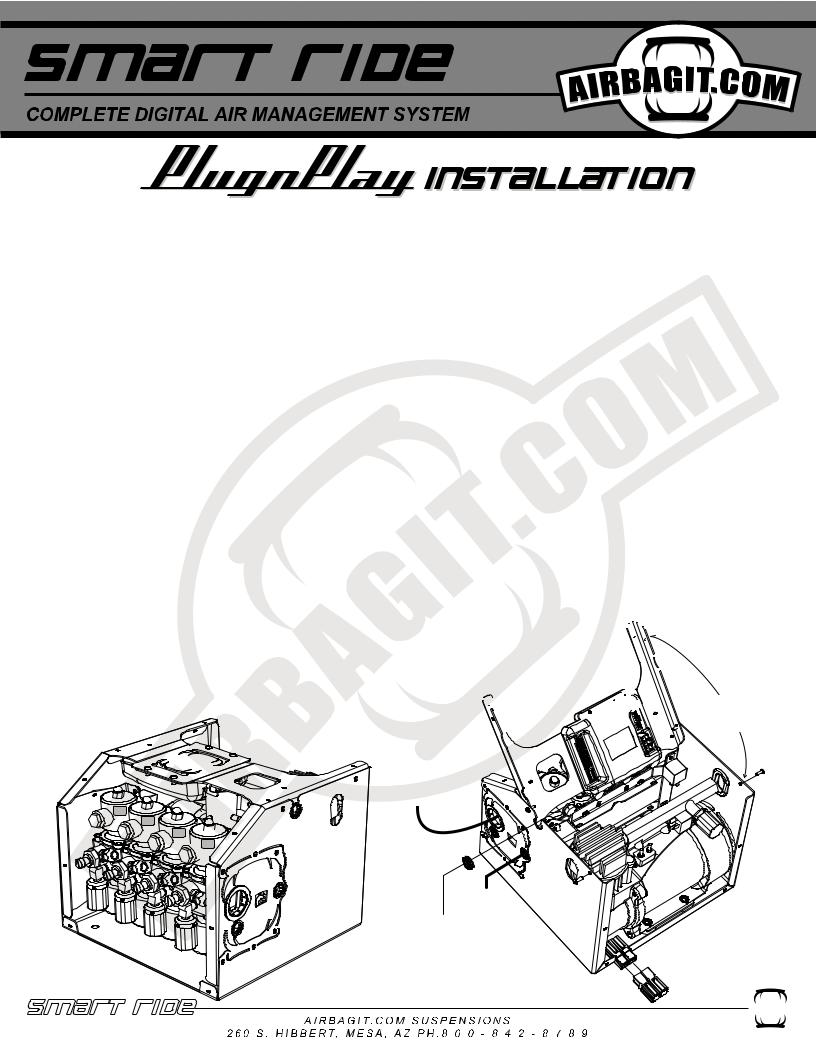
2.Remove top of Plug n Play by removing external screws with supplied bit.
3.Mount the Plug n Play in a dry location. It is recommended that you leave 5.5”-6” of room free in front of the PnP for valve removal.
4.Install tank and connect a line to the tank from the compressor and a second line back to checked inlet of the PnP.
5.Install tank pressure sender. Use the supplied Spanner Wrench to tighten the sender. Do not Overtighten.
6.Route the sender wire from the sender through the Plastic Grommit and into the PnP. Plug the connector in.(See Figure below)
7.Route Airbag airlines through the large grommet and connect to the valves. See figure below for valve assignments.
8.Run the 8 gauge power wire to the battery and connect through the supplied 60Amp brearker. Also, make sure the ground wire is connected to a clean part of the frame.
9.Route a seperate power wire from the battery to Red and Green Power wire of the Smart-Ride.
10.Route the 2 Smart-Ride ground wires out of the PnP Box and connect them to the same ground point as the PnP Ground.
11.Connect the Smart-Ride’s White wire to the cars ignition.
12.Locate a safe position for the LCD controller to be mounted. The controller can also remain loose and be handheld. Make sure the controller isn’t in a position where it can be accidentally activated while driving.
13.Route the LCD controller wire loom from the controller to the Plug n Play. The loom will pass through the small plastic grommet in the middle top of the Plug n Play. Do not plug LCD loom into the Relay control box yet.
14.Plug the Red and Black power connection into the Plug n Play.
15.Connect the vehicles battery.
16.Plug the LCD Controller into the Relay control box. The LCD display will turn on the run through its intialization process. Once the LCD turns on the compressor will start filling the tank. The display will show the tank pressure and the individual bag pressures. The height sensor will not display until they are connected.
17.Test the valves to make sure they are connected correctly.
18. Mount the height sensors (See Height Sensor Installation Section) and route 

 wires through the same grommet as the LCD loom. The height display for each corner

 will activate when the height sensor is connected to the relay control box.
  19. (Optional) Connect necessary “Optional Input Loom” to the third party controller. +12V Only
  20. Calibrate the height sensors. (See Calibration Section).


 21. Reinstall Plug n Play Top.


REMOVE SCREWS AND ROTATE TOP BRACE TO GAIN ACCESS TO THE SMART-RIDE RELAY CONTROL BOX
ROUTE AIRBAG AIRLINES
THROUGH LARGE GROMMET
RR
FR
RL 


 FL
FL
CHECKED VALVE
INLET PLUMB TO TANK
ROUTE SMART-RIDE’S RED
POWER WIRE, BOTH BLACK,
GROUND WIRES, THE
GREEN POWER WIRE,
HEIGHT SENSOR LOOMS
AND LCD CONTROLLER CABLE
THROUGH GROMMET
PLUG MAIN POWER
HARNESS IN BEFORE
CONNECTING THE LCD
CONTROLLER
2
1. Disconnect the negative battery terminal.
2. Mount the Smart-Ride in a dry location away from hot exhaust and any moving components. 3. Determine where the LCD Controller will be mounted.
4. Connect the LCD controller to the Relay Control Box. 5. Wire according to diagram on page 1.
a.Power Loom
i. Connect the Black wires (Pin 1 & Pin 3) to (-) Ground. ii. Connect the Red wire (Pin 2) to constant +12V.
iii. Connect the Yellow (Pin 4) to the Compressor (less than 40amp) or Compressor Relay (over 40amp draw).
1.This output is only designed to supply power to a compressor that requires less than 40 amps. Larger compressors must have a relay installed in between the Smart-Ride and the Compressor. (Wiring Schematics)`
iv. Connect the White wire (Pin 5)to an Ignition wire. This wire will turn the LCD Controller On. When the ignition turns on it will also activate Preset #1 if that option has been turned on (See Screen #2 instructions for details).
v. Connect the Green Wire to constant +12V (Pin 6). This wire will supply power to the internal relay that powers the Yellow Wire.
b.Valve Loom
i. Connect each wire to its corresponding valve as shown on the Non-PnP Wiring Schematic. ii. If you have purchased this Smart-Ride controller with one of Airbagit.com's Air Engine valve assemblies, or Air Force then the Valve Loom will plug right into the Air Engine's white 9 pin plug. See Air Engine Wiring Schematic.
The system will now have control of the valves but will not display pressures or heights until the sensors are installed.
c. Pressure Sending units (RED). (SMART-RIDE P and SMART-RIDE HP Models Only)
After the each Pressure Sending unit is installed you will see the tank pressure displayed on the LCD Controller.
i. Install the pressure sending units and plug into the red sockets on the relay control box as indicated on page 1. Note: Pressure Sending units are to be tightened with the included spanner wrench only, Tightening by hand will damage the sending unit.
ii.Smart-Ride P Models with speed control adjusters will need to make sure that the pres sure sender is installed between the bag and the speed control adjuster. Installing the pres sure sender after the speed control valve will cause inaccurate readings thus affecting the units ability to reach its preset values.
d.Height Sensors (BLUE). (SMART-RIDE H and SMART-RIDE HP Models Only)
i.SEE HEIGHT SENSOR INSTALLATION INSTRUCTIONS
e.Optional Inputs (These should be installed after the system has been completely installed and setup)
i.NOTE: THESE ARE ONLY TO BE CONNECTED IF YOU INTEND ON USING A THIRD PARTY CONTROLLER I.E. 12 CHANNEL REMOTE, OR ALARM SYSTEM. If you do not intend on controlling the Smart-Ride with anything other than the Smart-Ride LCD Controller then leave this loom unplugged.
ii.In order to use the optional third party inputs you will need to supply each wire with +12V. This is not a constant +12V but momentary power that is supplied by a third party controller.
3
 Loading...