

Air Taema NEFTIS ICU User manual
NEFTIS ICU
Taema
Maintenance Manual
YM027300 / Rev 0 / April 2006
Software Version V1.xx
www.airliquide.com
www.taema.com

2

Taema
NEFTIS ICU
CONTENTS
Preface.............................................................................................................................................................................. 5
Terminology .................................................................................................................................................................... 6
Typography ..................................................................................................................................................................... 7
General safety instructions......................................................................................................................................... 8
1. operation/description.......................................................................................................................................... 10
1.1. Operating Principle...................................................................................................................................... 10
1.2. Functional Description ............................................................................................................................... 10
1.2.1. Block Diagram of Operation .................................................................................................................10
Electronics........................................................................................................................................................... 11
Power supply ...................................................................................................................................................... 11
Front panel (indicator lights, screen, etc.) ...................................................................................................... 11
Pneumatic Mechanism...................................................................................................................................... 12
Pneumatic Operation......................................................................................................................................... 13
1.2.2. Pneumatic Cabling Diagram................................................................................................................. 15
1.3. Description .................................................................................................................................................... 16
1.3.1. Front View ............................................................................................................................................... 16
1.3.2. View of the expiratory unit..................................................................................................................... 16
1.3.3. Rear View................................................................................................................................................ 17
1.3.4. View from Above .................................................................................................................................... 17
1.3.5. Blower View ............................................................................................................................................18
1.3.6. Inside View of Rear Cover .................................................................................................................... 18
2. Maintenance .......................................................................................................................................................... 19
2.1. Special Tools................................................................................................................................................. 19
2.2. Preventive Maintenance............................................................................................................................. 20
2.2.1. Annual Maintenance.............................................................................................................................. 20
Required spare parts ......................................................................................................................................... 20
2.2.2. 20,000-Hourly Maintenance*................................................................................................................ 21
Required spare parts ......................................................................................................................................... 21
Recommended additional spare parts ............................................................................................................ 21
2.3. Disassembly/reassembly protocol.......................................................................................................... 22
Notes on how to avoid damaging the connections ....................................................................................... 22
2.3.1. Removing the Rear Cover .................................................................................................................... 23
2.3.2. Removing the Battery ............................................................................................................................ 25
2.3.3. Removing the Top Cover ...................................................................................................................... 26
2.3.4. Removing the Metal Frame .................................................................................................................. 28
2.3.5. Removing the Front ............................................................................................................................... 29
2.3.6. Replacing the Actuator Board .............................................................................................................. 33
2.3.7. Replacing the Power Supply Board..................................................................................................... 34
2.3.8. Replacing the Inspiratory Valve ........................................................................................................... 37
2.3.9. Replacing the Solenoid Valve Assembly............................................................................................ 38
2.3.10. Replacing the O2 Proportional Valve ................................................................................................... 39
2.3.11. Replacing the Flow Rate Sensor Assembly....................................................................................... 40
2.3.12. Replacing the Mixer ............................................................................................................................... 40
2.3.13. Replacing the Touch Screen ................................................................................................................ 41
2.3.14. Replacing the Microprocessor Board.................................................................................................. 44
2.3.15. Replacing the Blower Outlet Filter ....................................................................................................... 45
2.3.16. Removing the Blower ............................................................................................................................ 46
2.3.17. Replacing the O2 Connector Filter ....................................................................................................... 47
2.4. Corrective Maintenance ............................................................................................................................. 48
2.4.1. Alarm Messages..................................................................................................................................... 48
Troubleshooting for alarms 002 and 004........................................................................................................ 52
Troubleshooting for alarm 033 ......................................................................................................................... 52
2.5. Operation Monitoring and Calibration Protocols ................................................................................ 54
YM027300 / Revision 0 / April 2006
3

Taema
2.5.1. Preface..................................................................................................................................................... 54
2.5.2. Operation Check .................................................................................................................................... 54
2.5.3. Additional Checks .................................................................................................................................. 56
Mixer Airtightness............................................................................................................................................... 56
Inspiratory valve airtightness............................................................................................................................ 57
Blower .................................................................................................................................................................. 58
O2 Cell................................................................................................................................................................. 58
Nebulizer ............................................................................................................................................................. 58
2.5.4. Maintenance Mode ................................................................................................................................59
Accessing maintenance mode (Calibration) .................................................................................................. 59
Using Maintenance Mode ................................................................................................................................. 59
Calibrating the machine .................................................................................................................................... 59
Pressure sensor calibration.............................................................................................................................. 60
Calibrating the Low-Pressure Sensors (around 100 mbar) ......................................................................... 60
Calibrating the High-Pressure Sensor (approx. 3.5 bar).............................................................................. 62
Calibrating the NEFTIS ICU Flow Rate Sensors........................................................................................... 63
Calibrating the ventilation flow rate sensors ..................................................................................................64
Calibrating the actuators ................................................................................................................................... 67
Predictive Maintenance (under development) ............................................................................................... 68
2.5.5. Advanced Maintenance Mode.............................................................................................................. 69
Accessing Advanced maintenance mode ...................................................................................................... 69
Using Advanced Maintenance Mode .............................................................................................................. 69
2.5.6. Expert Mode............................................................................................................................................ 72
Introduction .........................................................................................................................................................72
Access ................................................................................................................................................................. 72
Use ....................................................................................................................................................................... 72
Description .......................................................................................................................................................... 74
NEFTIS ICU
3. Bill of Material....................................................................................................................................................... 75
3.1. Main Components........................................................................................................................................ 75
3.2. Kits and Miscellaneous Parts ................................................................................................................... 80
4. NEFTIS ICU Recommissioning Sheet............................................................................................................. 81
YM027300 / Revision 0 / April 2006
4

Taema
NEFTIS ICU
PREFACE
This document is a maintenance manual and is not intended to replace the user manual in any
way.
The objective of this document is to provide additional information to trained individuals who are
both competent and qualified to carry out preventive and/or corrective maintenance on NEFTIS
ICU KC023000 units.
It contains technical information that is the property of Taema and that may not be divulged without
the prior agreement of Taema.
YM027300 / Revision 0 / April 2006
5

Taema
NEFTIS ICU
TERMINOLOGY
Warning
Notifies the user of the possibility of a minor or serious injury that could arise when handling the ventilator,
whether correctly or incorrectly.
Attention
Notifies the user of the possibility of a technical problem or malfunction of the ventilator that could arise
when handling the ventilator, whether correctly or incorrectly.
Note
Highlights a piece of information.
YM027300 / Revision 0 / April 2006
6

Taema
TYPOGRAPHY
Font Example Function
NEFTIS ICU
Lucida Console, bold excessive pressure
See Section 3.1
Italic
Solenoid valve
Bold, italic
monitoring patient exhalation
Text from the screen
Text referring to another section of
the manual.
Text in the index
Highlights an important point in a
sentence.
YM027300 / Revision 0 / April 2006
7

Taema
NEFTIS ICU
GENERAL SAFETY INSTRUCTIONS
P
RECAUTIONS FOR OXYGEN USE
− No incandescent source nearby
− No fatty substances.
P
RECAUTIONS IN THE EVENT OF AN OXYGEN LEAK
− No smoking
− Avoid all sources of flame or spark
− Close the oxygen supply valve
− Air the room while there is a leak and for at least 20 minutes afterwards
− Air one's own clothing.
ELECTRICAL SUPPLY
− Check that the voltage in the mains plug used correctly corresponds to the electrical
characteristics of NEFTIS
− As NEFTIS
ICU has an internal battery, it is preferable to leave the unit plugged into the
electrical power supply, with the On/Off switch in the On position in STANDBY mode, to keep
the battery charged.
− If it is stored, the NEFTIS ICU should be charged regularly with the On/Off switch in On
position, connected to the electrical power supply, in STANDBY mode, for at least 10 hours, to
keep the battery charged. The interval between two recharges must not exceed three weeks
(batteries charged),
− In the event of prolonged storage (more than three weeks), keep the battery disconnected.
When returning the unit to service, perform a test of battery characteristics (see Section 2.5.5).
P
UTTING NEFTIS ICU IN SERVICE
− Before each use, check that the audible and visual alarms (red indicator on keyboard) are
operative, and carry out checks as listed in the 'recommissioning' sheet.
E
LECTROMAGNETIC COMPATIBILITY
− NEFTIS
− NEFTIS
ICU conforms to the protection requirements of Directive 93/42/CEE.
ICU operation can be affected by the use of appliances in its immediate proximity,
such as diathermic, high frequency electro-surgery units, defibrillators, cell phones or, more
generally, by electromagnetic interference that exceeds the levels set by standard EN 60 6011-2.
A
T HIGH AMBIENT TEMPERATURE
− The NEFTIS
ICU ventilator heats the respiratory gas by 4 to 6°C above the ambient
temperature according to the parameters selected. At ambient temperatures over 35°C, the
respiratory gas temperature can exceed 40°C. In this case, the ventilator will trigger an alarm.
I
N THE EVENT OF OXYGEN SUPPLY FAILURE
− In normal operation, the NEFTIS
coming from the central supply or a cylinder, at ratios depending on the FiO
supply fails, the NEFTIS ICU replaces the unavailable oxygen with ambient air. All ventilation
parameters are maintained, except for the FiO
informs you of the situation.
ICU (indicated on the manufacturer's plate on the rear panel).
ICU delivers a mixture composed of ambient air and oxygen
setting. If the O
2
, which becomes equal to 21%. An alarm
2
2
YM027300 / Revision 0 / April 2006
8

Taema
NEFTIS ICU
USING THE NEFTIS ICU
In compliance with standard EN 60 601-1 (Appendix A Para. 6.8.2.b):
"The manufacturer, assembler, installer or importer only consider themselves responsible for the
safety, reliability and characteristics of a unit if the:
Assembly, extensions, settings, changes or repairs were carried out by personnel authorized by
them,
− Electrical installation of the corresponding area is compliant with IEC recommendations,
− Unit is used in compliance with the instructions for use.
If the accessories used by a user do not conform to the manufacturer’s instructions, the
manufacturer is relieved of all responsibility in the event of an incident.
If spare parts used during scheduled maintenance do not conform to the manufacturer’s
specification, the manufacturer is relieved of all responsibility in the event of an incident.
− Ventilation must not be started immediately after storage or transportation under conditions
that differ from the recommended operating conditions.
− NEFTIS
ICU must not be used with inflammable anaesthetic agents or explosive products.
− Do not use anti-static or electrically conductive ducts or tubes.
− NEFTIS
− For correct operation of the NEFTIS
ICU must not be used exposed to direct sunlight.
ICU, maintain free circulation of air, keeping rear and
underneath air inlets completely unobstructed.
The manufacturer has anticipated the majority of possible malfunctioning cases for NEFTIS and
these are normally covered by the internal monitoring system. It is nevertheless recommended, in
case of complete patient dependence, to provide an additional system that is completely
autonomous, and which can be used to check the effectiveness of the ventilation, as well as an
emergency device, such as a manual IM5 insufflator.
C
LEANING AND MAINTENANCE OF NEFTIS
− Do not use abrasive powders, alcohol, acetone or other easily flammable solvents.
− NEFTIS
ICU must be checked on a regular basis. To schedule and record maintenance
operations, refer to the maintenance sheet in the user manual.
YM027300 / Revision 0 / April 2006
9
Taema
NEFTIS ICU
1. OPERATION/DESCRIPTION
1.1. OPERATING PRINCIPLE
The blower is controlled by a microprocessor and is slaved to a volume control unit or a pressure
control unit according to the selected ventilation mode.
NEFTIS
The mixer provides a precise and variable concentration between 21% and 100% oxygen.
The O
The expiratory circuit includes:
The expired gas flow rates are measured by the hot wire sensor whose signal is processed by the
electronics to obtain spirometry data.
ICU does not generate negative pressure during the expiratory phase.
concentration of the insufflated mixture is measured by the FiO2 sensor.
2
• a two-way patient valve,
• an expired gas flow rate sensor (hot wire);
• a special trap.
1.2. FUNCTIONAL DESCRIPTION
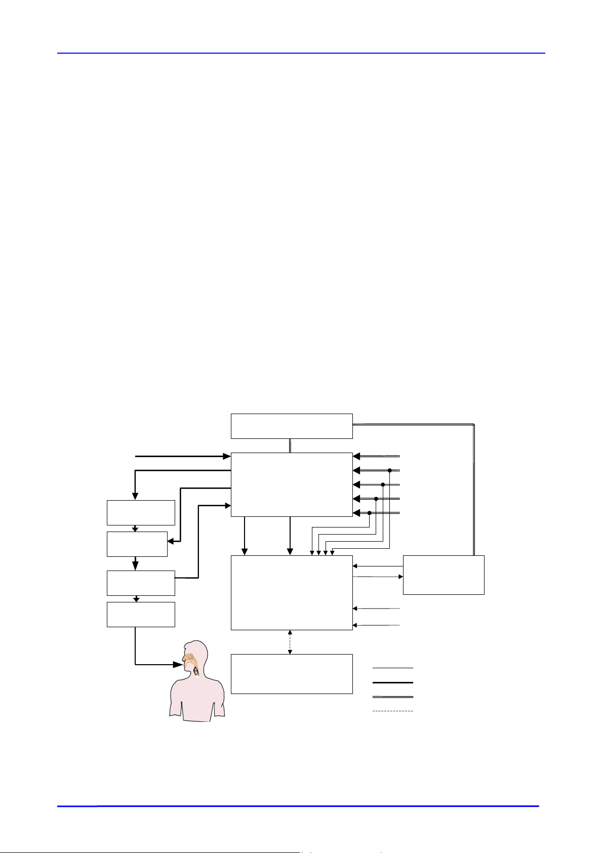
1.2.1. BLOCK DIAGRAM OF OPERATION
O2 supply
Gaseous mixture
Patient tube
V. exp
Flow ctrl
Mask or
probe
PEEP control
Pressure
measure
Flow measurement
Mechanism (housing)
Ventilation/pneumatic unit
measure
ment
Microprocessor board
Flow
ment
Electronics
Ventilator µP
Monitor µP
Inputs/Outputs
Settings:
PEEP,
Vt,
Freq,
Alarms, etc.
Touch screen
Front panel
LEDS
Mains power supply
Battery
Patient
Software:
Ventilator
Monitor
Electrical connection
Pneumatic connection
Mechanical connection
Logic connection
YM027300 / Revision 0 / April 2006
10

Taema
NEFTIS ICU
ELECTRONICS
HE MICROPROCESSOR BOARD
T
The microprocessor board consists of two identical central processor units from Motorola, split into
two sub-systems:
The ventilator:
This sub-system is the processor dedicated to ventilation. It integrates the electronic
conditioning stages associated with the sensors and the control of the electro-pneumatic
components, the audible alarms, a dialog link and the exchanges with the monitor.
The monitor:
integrates a screen, the information exchange medium between the user and the NEFTIS
This sub-system is the MMI (Man Machine Interface) dedicated processor. It
ICU and
the electronic stages associated with the safety and the redundancy of the controls for certain
components and alarms, as a link to the ventilator.
T
HE ACTUATOR BOARD
The actuator board includes all the actuator power controls (solenoid valve, valves, blowers, etc.).
POWER SUPPLY
The board power supply supplies power to the microprocessor board and to all the pneumatic
actuators. This power can be supplied from the mains, from a direct current source connected to
the NEFTIS
device. The power supply board performs automatic switching between these different power
sources and informs the microprocessor board of the power sources available.
Linked to this sub-assembly, the internal battery provides a back-up power supply if the two other
power sources are lost.
However, the microprocessor board has a power supply cut-off command via the internal battery,
in case battery protection is necessary.
ICU, known as an external DC source, or from the internal backup battery built into the
FRONT PANEL (INDICATOR LIGHTS, SCREEN, ETC.)
The NEFTIS
controlled by the processor board. This screen is only visible thanks to its backlighting.
The front panel is also equipped with LEDs indicating functions such as alarms and operational
modes in NIV (Non-Invasive Ventilation). These displays are implemented on the microprocessor
board.
The front panel, at MMI level, has an interface with touch keys (touch-screen), a navigation coding
wheel allowing the user to set and confirm parameters. Access is also possible by selecting the
configuration zone from the touch-screen (dual access).
ICU screen consists of an LCD colour display equipped with CCFL back-lighting
YM027300 / Revision 0 / April 2006
11

Taema
NEFTIS ICU
PNEUMATIC MECHANISM
ECHANICS
M
The pcb supports all the pneumatic components (solenoid valve, valve, flow rate sensor etc.). The
pcb is mechanically decoupled from the housing.
The blower enclosure unit
plate of the housing.
The rear cover
: covers the blower/mixer assembly and the internal battery unit. The NEFTIS ICU
access and interface assembly is located on the rear plate (mains power, external DC, RS232, O2
inlet, etc.).
T
HE COMPLETE PNEUMATIC CIRCUIT
The complete pneumatic circuit consists of an assembly of components performing the pneumatic
function of the NEFTIS
Mixer
: The principle of this sub-system is to provide a precise and variable concentration between
21% and 100% oxygen.
Blower
: This sub-system facilitates the supply of a gas flow at a given pressure.
The inspiratory assembly
pressure from an assisted valve.
The expiratory assembly:
control of the pressure level (PEEP).
The electro-pneumatic components
: The blower associated with an air/O2 mixer is integrated in the rear
ICU. This simple system is sub-divided into five sub-systems:
: This sub-system allows the control of a flow rate or an inspiratory
This sub-system facilitates the evacuation of an expiratory flow rate with
(sensors and actuators).
YM027300 / Revision 0 / April 2006
12
Taema
A
e
NEFTIS ICU
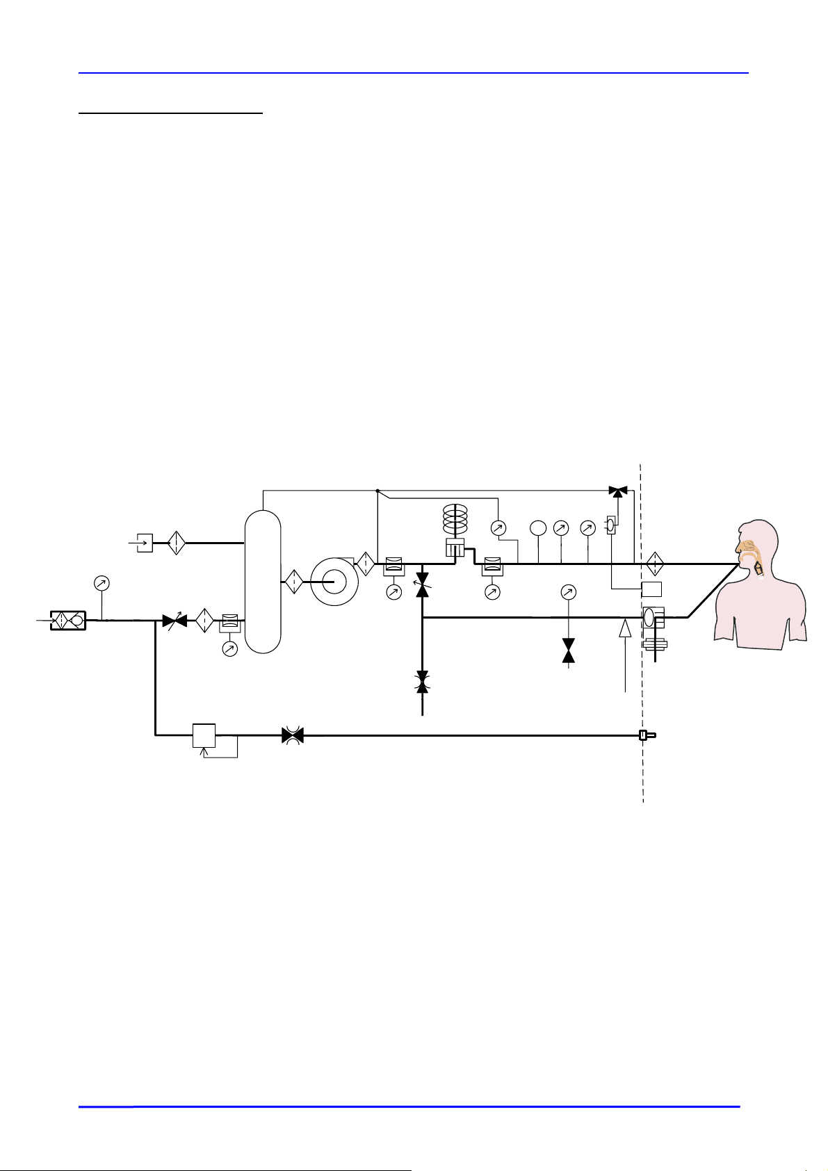
PNEUMATIC OPERATION
1 : Inspiratory valve
4 : PEEP proportional solenoid valve
5 : Blower
6 : Enclosure/Mixer
7 : Expiratory valve
8 : O
proportional solenoid valve
2
9 : Expiratory flow sensor (hot wire)
10 : Inspiratory flow sensor (Honeywell)
11 :
O
flow sensor
2
12a,12b: Pressure sensors
13 : Balloon pressure sensor
14 : Ambient air inlet/safety valve
15 : Air intake
15 b: Air inlet filter
16 : O2 CELL
17 : I/E cycle management solenoid valve
18 : Solenoid drain valve
19 : Blower outlet flow sensor
20 : Blower outlet particle filter
21 : Insp ∆P pressure sensor
22 : O
pressure sensor
2
23 : Nebulizer reducer
24 : Nebulizer solenoid valve
25 : O
connector
2
26 : Bacteriological filter
27 : Patient gas temperature sensor
28 : Laminar filter
29 : Blower inlet filter
30 : Ambient air connector 3/2 solenoid valve
O2
30
25
22
IR
15
15 B
8
N.F
28
23
11
6
29
24
5
20
19
1
10
4
17
Nebulizer circuit
21
27
T
12a
18
PEEPcircuit
12b
13
14
26
O2
16
7
9
The administering of ventilation cycles to a patient by NEFTIS ICU is the result of action involving
three essential components: the pressure generator (the blower), the inspiratory valv
(electro-pneumatic) and the PEEP solenoid valve (proportional solenoid valve).
Patient
YM027300 / Revision 0 / April 2006
13

Taema
NEFTIS ICU
THE PRESSURE GENERATOR
The role of blower (5) is to guarantee the pressurisation required to deliver a ventilation cycle that
conforms to the settings.
This blower draws the gaseous mixture from enclosure/mixer (6). Via O
proportional solenoid
2
valve (8) – connected to the network – this mixture can contain a variable rate of oxygen, from
21% to 100%.
For the following description of the inspiratory and expiratory phases, it is assumed that blower 5a
has pressurized the circuit sufficiently.
NSPIRATORY PHASE
I
PEEP proportional solenoid valve (4) is kept open and both I/O solenoid valves (17) and (18)
(position open or closed) are closed.
The output pressure from the blower is therefore at the level of the expiratory valve and thus
seals the part of the circuit located between the patient and the expiratory valve.
In other words, the gaseous flow is forced to focus on the patient only and cannot escape into the
atmosphere.
The inspiratory cycle delivered to the patient is a result of the setting of inspiratory valve (1). If the
mode selected is barometric, the inspiratory valve regulates in relation to the pressure sensor
which indicates the highest value (12b if 12a is inoperative or inversely). If the mode selected is
volumetric, the inspiratory valve regulates in relation to the flow rate sensor which indicates the
highest value (10) (19 if 10 is inoperative or inversely).
E
XPIRATORY PHASE
In this phase, a PEEP level must be set. To do this, open at least one of the I/O solenoid valves
(17 and 18) in order to lower the pressure applied to the expiratory valve membrane (this same
pressure guarantees the leak-tightness of the inspiratory phase) and proportional solenoid valve
4 controls the PEEP level required via pressure sensor P12a.
During this time, the inspiratory valve guarantees the flow rate regulation function via sensor (10).
This flow rate allows rinsing of the circuit and easier detection of any inspiratory call by the patient.
Note
During NIV ventilation (thus leakage ventilation), the inspiratory valve can fulfil the additional role
of an on-demand valve by adjusting the set pressure level if the leaks are too great.
UNCTION OF THE EXPIRATORY UNIT
F
The expiratory valve is integrated into this unit and a hot wire flow-rate sensor is added to
measure the flow-rate exhaled by the patient. The restriction allows a reduction of the sound
produced by the expiratory bag in the presence of PEEP.
A silicone disc is inserted in the bag to absorb vibrations.
The ambient air plug valve enables the patient to breathe through the machine when it is switched
off, with a resistance less than 6 hPa.
YM027300 / Revision 0 / April 2006
14
Taema
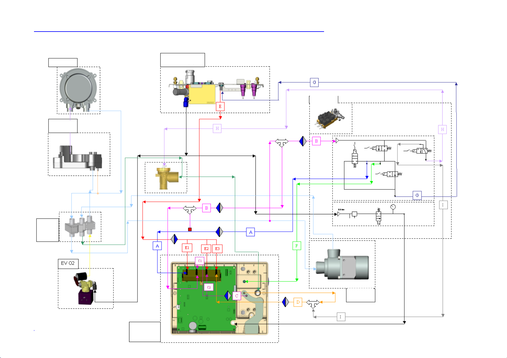
1.2.2. PNEUMATIC CABLING DIAGRAM
Blower
NEFTIS ICU
Rear sheet assembly
5
25
Flow
sensors
Block
Enclosure
6
mixer
19
10
11
Safety
valve
22
4
PEEP unit
18
Reducer
23
4
24
17
30
Nebulizer
output
8
12a
12b
Front panel
assembly
13
21
YM027300 / Revision 0 / April 2006
1
Inspiratory
valve
15
Taema
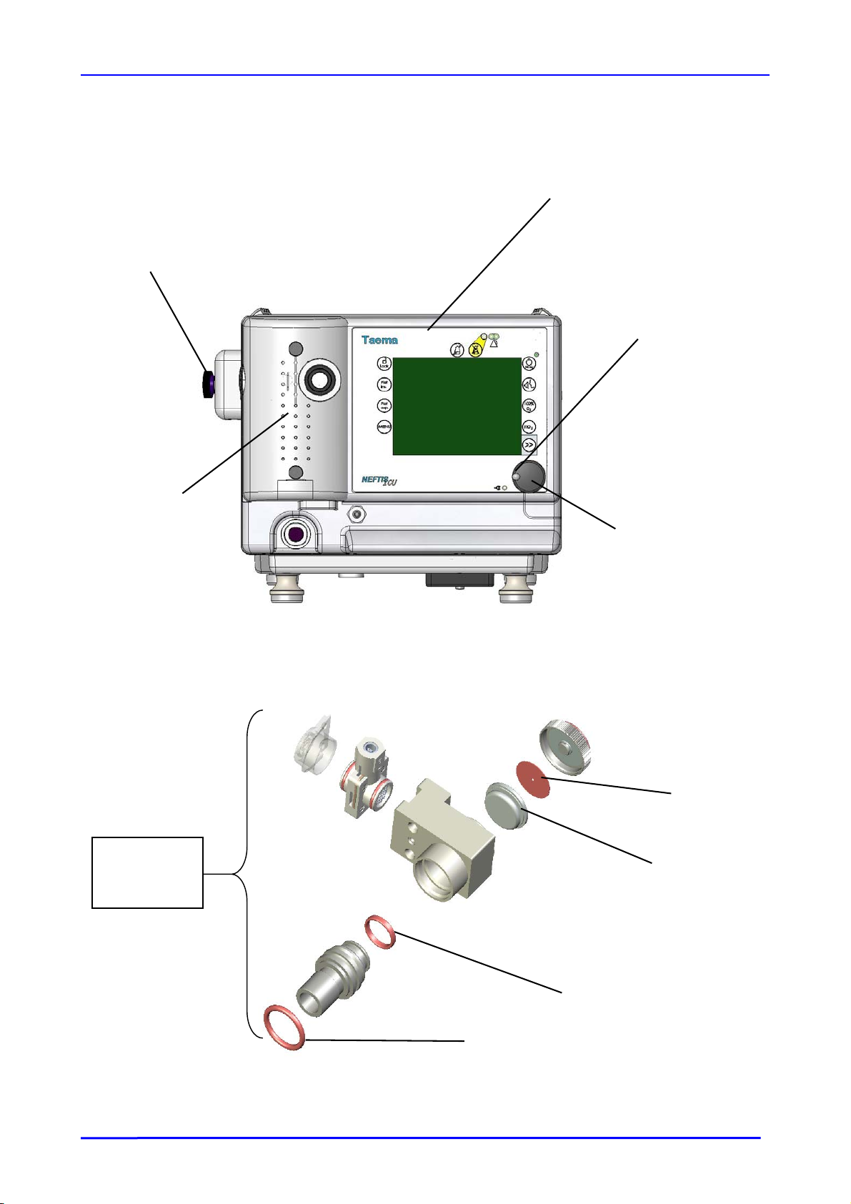
1.3. DESCRIPTION
NEFTIS ICU
Mounting
knob
Expiratory
valve trap
1.3.1. FRONT VIEW
Touch screen
Milled screw
spherical end
Milled screw
Expiratory
1.3.2. VIEW OF THE EXPIRATORY UNIT
valve
assembly
Exp valve disc
Expiratory
valve
membrane
O-ring
O-ring
YM027300 / Revision 0 / April 2006
16
Taema
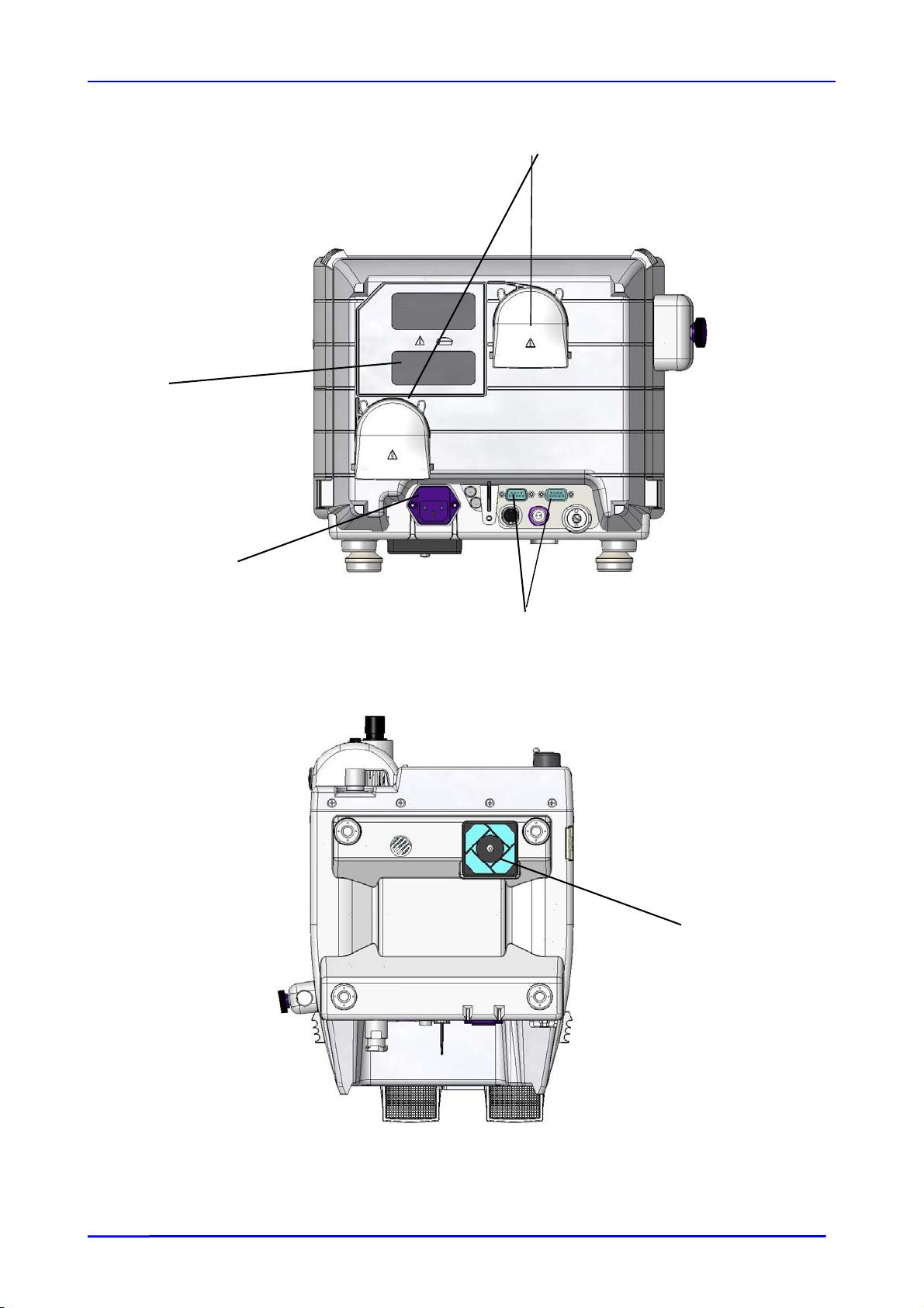
r
1.3.3. REAR VIEW
Rear cover
filte
NEFTIS ICU
Deflector
Power supply
connector
fuses
1.3.4. VIEW FROM ABOVE
Sub D board RS232
connectors
Base fan filter
YM027300 / Revision 0 / April 2006
17
Taema
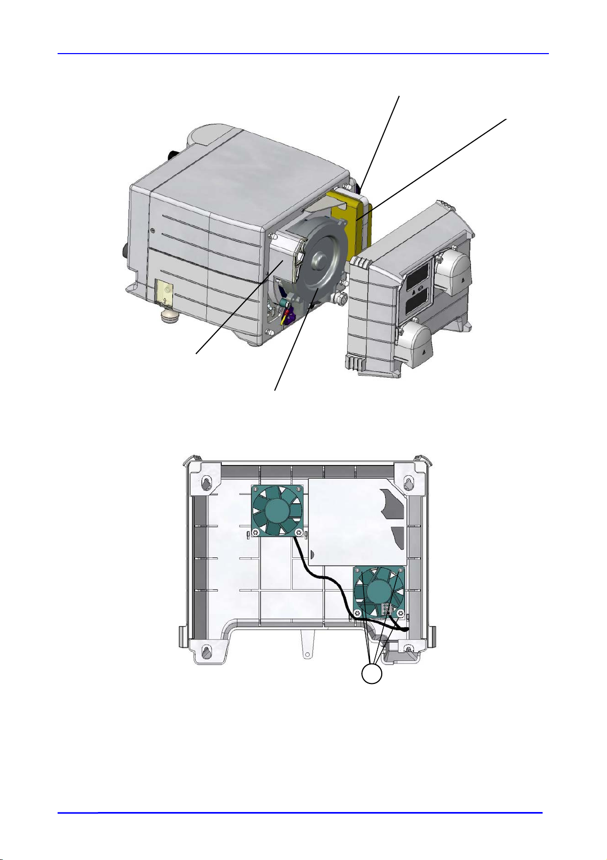
r
r
1.3.5. BLOWER VIEW
NEFTIS ICU
Battery mounting
blade
Battery
Mixe
enclosure
Blowe
1.3.6. INSIDE VIEW OF REAR COVER
23
YM027300 / Revision 0 / April 2006
18

Taema
2. MAINTENANCE
NEFTIS ICU
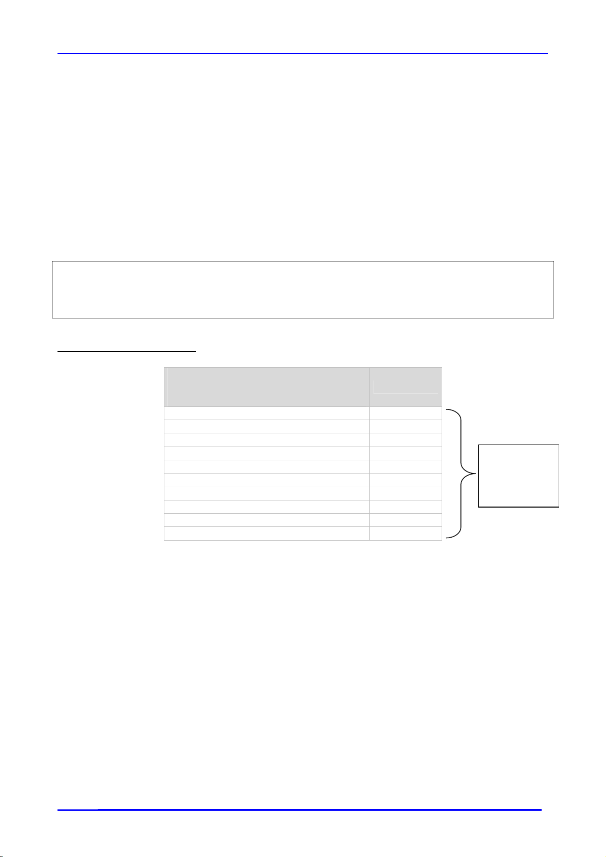
2.1. S
Pressure gauge, 0 – 5 bar Class 1 X X X
O2 connector disassembly key YA004400 X X X
Siemens test lung VS206103 X X X
Integrator test lung KY000600 X X X
Red restriction for integrator test lung KY241800 X X X
Pressure connector T-fitting X X X
Syringe X X X
Digital voltmeter X X
External oxygen meter X X
Pressure gauge, 0 – 100 mbar Class 1 X X X
3-gas connector monitoring pressure gauge BJ060900 X X
Mixer blanking plate YA017200 X X
Battery maintenance cable YA017300 X X X
PECIAL TOOLS
Type of unit Part No.
Type of maintenance
Annual
4
yearly
Correctiv
e
YM027300 / Revision 0 / April 2006
19
Taema
NEFTIS ICU
2.2. PREVENTIVE MAINTENANCE
2.2.1. ANNUAL MAINTENANCE
1- Internal dusting of device
2- Replace the four blue pressure sensor filters
3- Replace the blower output filter
4- Replace the blower dust filters located at the back of the unit
5- Replace the ventilator dust filter underneath the device
6- Replace the oxygen connector check valve end guide
7- Replace the O-rings of the black sleeve on the expiratory unit
8- Replace the expiratory valve membrane and disc
9- Replace the O-ring on the expiratory valve control pressure connector
10- Carry out a check on machine performance
Note
Whenever an internal component of the NEFTIS ICU is replaced (pressure sensor, flow rate
sensors, microprocessor board, blower, etc.) the full adjustment and checking procedure should be
carried out.
REQUIRED SPARE PARTS
DESCRIPTION
Acrodisc filters 5
Blower outlet filter 1
Rear cover filter 1
Base fan filter 1
Check valve end guide 1
Sleeve O-ring 1
Sleeve O-ring 1
Exp valve membrane 1
Exp valve disc 1
Exp valve connector O-ring 1
Standard maintenance time: 3 hours.
Equipment downtime: 12 hours.
QUANTITY
NEFTIS ICU
ANNUAL
MAINT. KIT
KC026300
YM027300 / Revision 0 / April 2006
20
Taema
2.2.2. 20,000-HOURLY MAINTENANCE*
1- Internal dusting of device
2- Replace the four blue pressure sensor filters
3- Replace the blower outlet filter
4- Replace the blower dust filter located at the back of the unit
5- Replace the fan dust filter underneath the device
6- Replace the oxygen connector check valve end guide
7- Replace the O-rings of the black sleeve on the expiratory unit
8- Replace the expiratory valve membrane and disc
9- Replace the O-ring on the expiratory valve control pressure connector
10- Replace the blower
11- Carry out a check on machine performance
REQUIRED SPARE PARTS
DESCRIPTION
Acrodisc filters 5
Blower outlet filter 1
Rear cover filter 1
Fan filter 1
Check valve end guide 1
Sleeve O-ring 1
Sleeve O-ring 1
Exp valve membrane 1
Exp valve disc 1
Exp valve connector Oring
Blower 1
MOLEX housing for
female contact
Standard maintenance time: 4 hours.
Equipment downtime: 12 hours.
QUANTITY
1
1
NEFTIS ICU
NEFTIS ICU
20,000-HR
MAINT. KIT
KC026400
RECOMMENDED ADDITIONAL SPARE PARTS
DESCRIPTION
INTERNAL BATTERY KY569400 1
LITHIUM BATTERY, 3.6V
½ AA
OXYGEN CELL YR049700 1
LCD CCFL
FLUORESCENT TUBE
Note
Required spare parts are not include in the maintenance kit. However these parts could be replace
in maintenance. Therefore it’s recommended to have them during an intervention.
YM027300 / Revision 0 / April 2006
REFERENCE QUANTITY
VS106125 1
KY620500 1
21

Taema
NEFTIS ICU
2.3. DISASSEMBLY/REASSEMBLY PROTOCOL
Any removal of a component part of the NEFTIS
always requires a full check of the device (see level 2 recommissioning sheet).
NOTES ON HOW TO AVOID DAMAGING THE CONNECTIONS
YPE ELECTRICAL CONNECTORS
KK-T
These connectors should normally be removed by lifting the plastic clips and then pulling on the
cable.
H
OSES ON THE ELECTRONIC PRESSURE SENSORS
The hoses should be removed from the electronic pressure sensors by pulling the hose with
moderate force whilst working the hose clear of the sensor cable support sleeve.
Avoid placing any mechanical stress on the sensor itself. Mechanical stress could sever the
electrical tabs of these sensors.
If possible, do not disconnect the hose from the sensor olive connector side, but from the Y-
piece connector side. Handle the olive connectors with care.
Avoid the application of any sudden depressurising or overpressure to the sensor. To do this, do
not clamp the tube fully when connecting and de-connecting.
P
OLYURETHANE TUBE
®
A Polyurethane
− Firstly, perform the same action as when connecting the pipe in the quick-fit connector.
− When it is at the bottom of its housing, press on the black bushing, hold it down, and
Reinstallation is not difficult, but it is advisable to ensure that the tube is sufficiently lodged in its
housing (5 to 8 mm) to avoid any leakage.
H
ANDLING OF COMPONENTS (AND ELECTRICAL CONTACTS IN GENERAL)
The tabs of components (e.g.: EPROM) and all the components intended to go in electrical
contacts (e.g. connector base) should not be touched, because they are affected by the acidity of
the skin.
E
LECTRONIC BOARDS
Use an anti-static apron when handling an electronic board.
If you remove the board, place the soldered side on an antistatic apron (code VS206001).
Handle with care and without applying any mechanical stress. Be aware of the relative mechanical
fragility of the SMDs (surface mount devices).
The disassembly/reassembly of the microprocessor board must be performed with care. In particular,
tools must not be allowed to slip, in case they damage the surrounding components or tracks.
E
LECTROSTATIC CHARGES
Before touching a component, touch an earthing connection to ensure that you are free of
electrostatic charges.
tube is removed in two steps.
pull on the pipe. The tube comes out easily.
ICU, except the rear cover and the top cover,
YM027300 / Revision 0 / April 2006
22
Taema
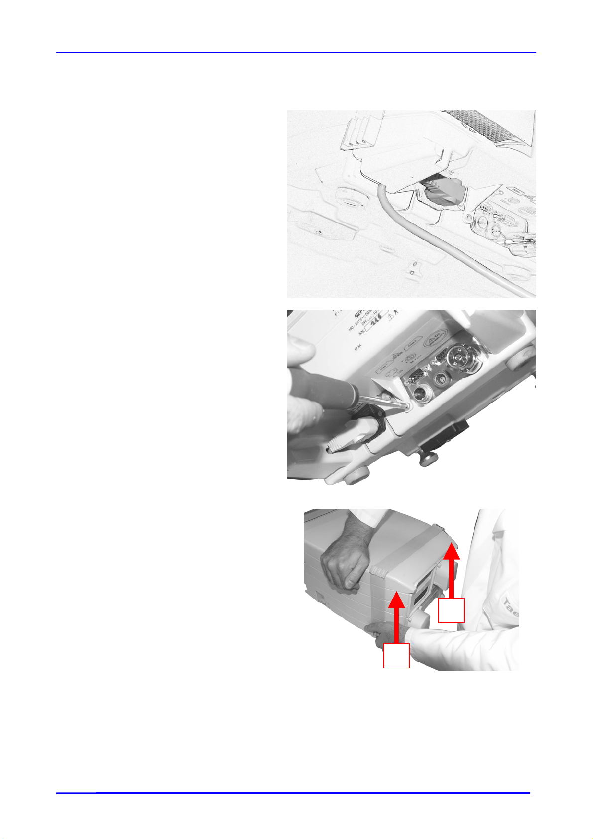
2.3.1. REMOVING THE REAR COVER
• Position the mains cable as follows
NEFTIS ICU
• Remove the screw from the rear cover
• Disconnect the mains cable
• Lift the rear cover by the left side (1) and
then by the right side (2)
2
1
YM027300 / Revision 0 / April 2006
23
Taema
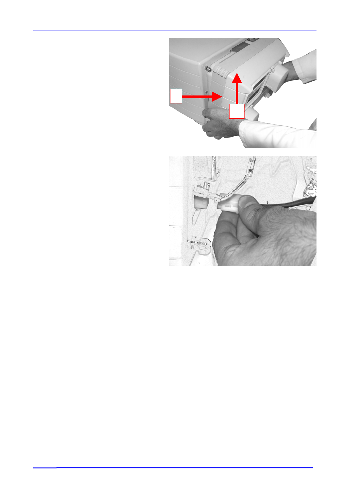
1
• Pull (1) and then lift (2) the cover clear.
NEFTIS ICU
2
• Disconnect the strand from the fans.
• Remove the rear cover
YM027300 / Revision 0 / April 2006
24
Taema
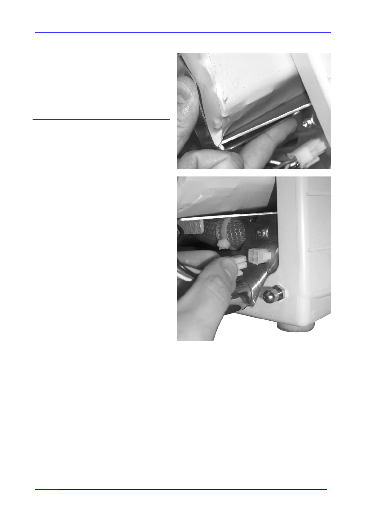
2.3.2. REMOVING THE BATTERY
Remove the rear cover (See Section
•
2.3.1)
Warning
The battery blade must be handled with
care.
• Unclip the lower blade using your middle
finger, whilst holding it with your thumb (see
photo).
NEFTIS ICU
• Disconnect the battery strand.
• Remove the battery.
YM027300 / Revision 0 / April 2006
25
Taema
2.3.3. REMOVING THE TOP COVER
• Remove the rear cover and the battery
blade (See Sections 2.3.1 and 2.3.2)
Note
Leave the battery connected to avoid being
subjected to a loud noise.
• Remove the three M4 Phillips head
screws at the rear of the upper cover.
NEFTIS ICU
• Remove the mounting lugs at the rear of
the upper cover.
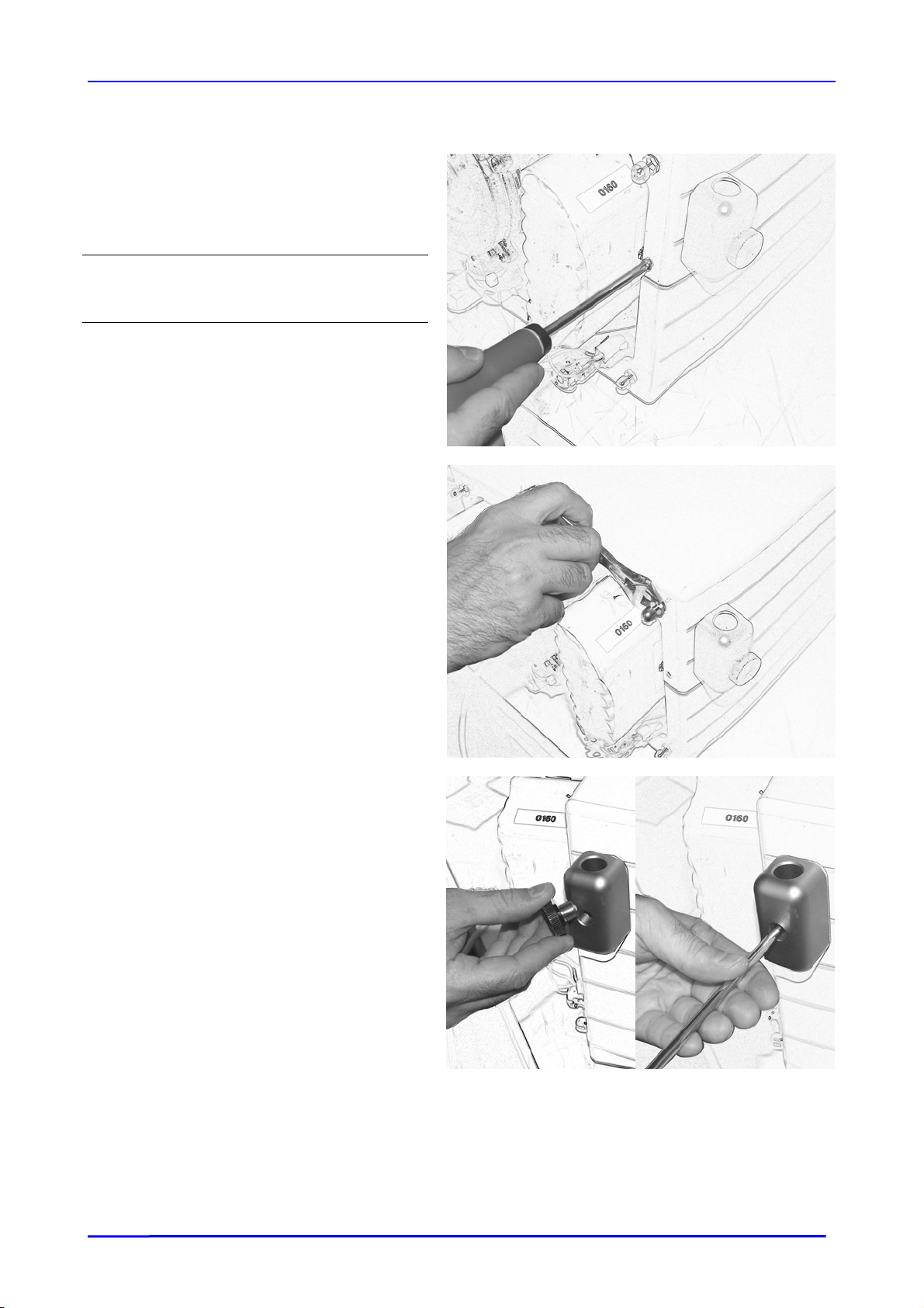
• Remove the milled screw and the arm
support screw.
YM027300 / Revision 0 / April 2006
26
 Loading...