

Air Shields 7865 Service manual
SERVICE
MANUAL
AIR-SHIELDS
BIRTHING
SYSTEM
7865
Air-ShieldsV
®
ROOM
WARMER
Vickers
Medical

The
productbeing
workmanshipfor
the
following exceptions.
All
consumable
upon
shipment
described
one
year
and
disposable
only.
LIMITED
WARRANTY
inthis manual iswarranted
from
the
date
of shipment from Air-Shields, Hatboro, with
products
are
guaranteedtobe
against
defects
free from
in materialsor
defects
Calibrations
1
year
During the warranty period
placed at no charge to the customer. There
parts
within
are
warranty.*
the
continental U.S
considered
normal
any
defective parts
maintenance
other
will
and
are
not
than
those
included
listed
above
in
the
willbere
be no labor charge for replacing the
1. Damage to the unit is incurred as a result of mishandling.
2. The customer fails to maintain the unit in a proper manner.
3. The customer
by
Air-Shields.
uses
any parts, accessories, or fittings not specifiedor sold
4. Sale or service is performed by a non-certified service/dealer agency.
This warranty is inlieu of all other warranties, expressed or implied,and Air-Shields
shall innoeventbe liableforincidentalorconsequential damagesincludinglossofuse,
property damage, or personal
The
AccreditationManualforHospitalsrequireseach piece ofequipmentto be tested
initial
priorto
use and at least annually thereafter. To comply withthis standard, we
injury
resultingfrombreach of warranty.
recommend that you participateinourAccreditation TestingCompliance Program dur
ingthewarrantyperiod.Thisservicecan be performed bycertified technicians through
our
Product
Service
Group
and
authorized
dealers.
.
Foroptimal performance, productservice should be performed onlybyqualifiedserv
icepersonnel. ProductServiceGroupinstrumentation specialistsare locatedthrough
out the United States and are dispatched for required maintenance by calling
800-523-2404.
ized
Air-Shields
Cat.
No.78991
EX£A4
5 6 7 8 9
[lM3)4 5 6 7 8 9
SERVICE
Customersoutsidethe U.S. should contacttheir local factory-author
distributor
51-6
for
service.
Air-Shields \
330
Jacksonville
^S»7
Vickers
Medical
Rd.,Hatboro,PA19040
Printed
(Change 1)
(Change 2)
(Change
(Change
(Change
in
U.S.A.
3)
4)
5)
9/87
3/88
8/89
1/91
10/91
6/92
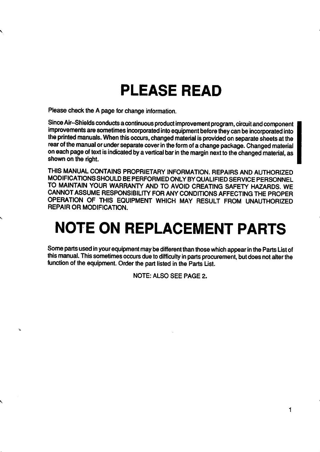
PLEASE
READ
Please check the A page
Since
Air-Shields
improvements
the
printed
rear
ofthe
manualorunder
oneach
shown on the right.
THIS
MODIFICATIONS SHOULD BEPERFORMEDONLY BY
TO
CANNOTASSUME RESPONSIBILITYFORANY CONDITIONS AFFECTING THE PROPER
OPERATION OF THIS
REPAIR
page
MANUAL
MAINTAIN
OR
conductsacontinuous
are
sometimes
manuals.
oftextis
CONTAINS PROPRIETARY
YOUR WARRANTY AND TO
MODIFICATION.
NOTE
Some
parts
usedinyour
this
manual.
function
Thissometimes
ofthe equipment.
When
indicated
ON
equipment
for
change
incorporated
this
separate
EQUIPMENT
information.
occurs,
coverinthe
bya
vertical
product
into
equipment
changed
barinthe
INFORMATION.
AVOID
WHICH
improvement
materialisprovidedonseparate
form
ofa
margin
QUALIFIED
CREATING SAFETY HAZARDS. WE
MAY RESULT
REPLACEMENT
occurs
Order
maybedifferent
dueto
difficultyinparts
the
part
listedinthe
NOTE:
ALSO
SEE
than
Parts
PAGE
those
program,
before
circuit
and
they
canbeincorporated
sheetsat
change
package.
nexttothe
REPAIRS AND AUTHORIZED
FROM
Changed
changed
SERVICE PERSONNEL
material,
UNAUTHORIZED
PARTS
which
appearinthe
procurement,
List.
2.
butdoes not
Parts
component
into
the
material
as
List
alter
the
of
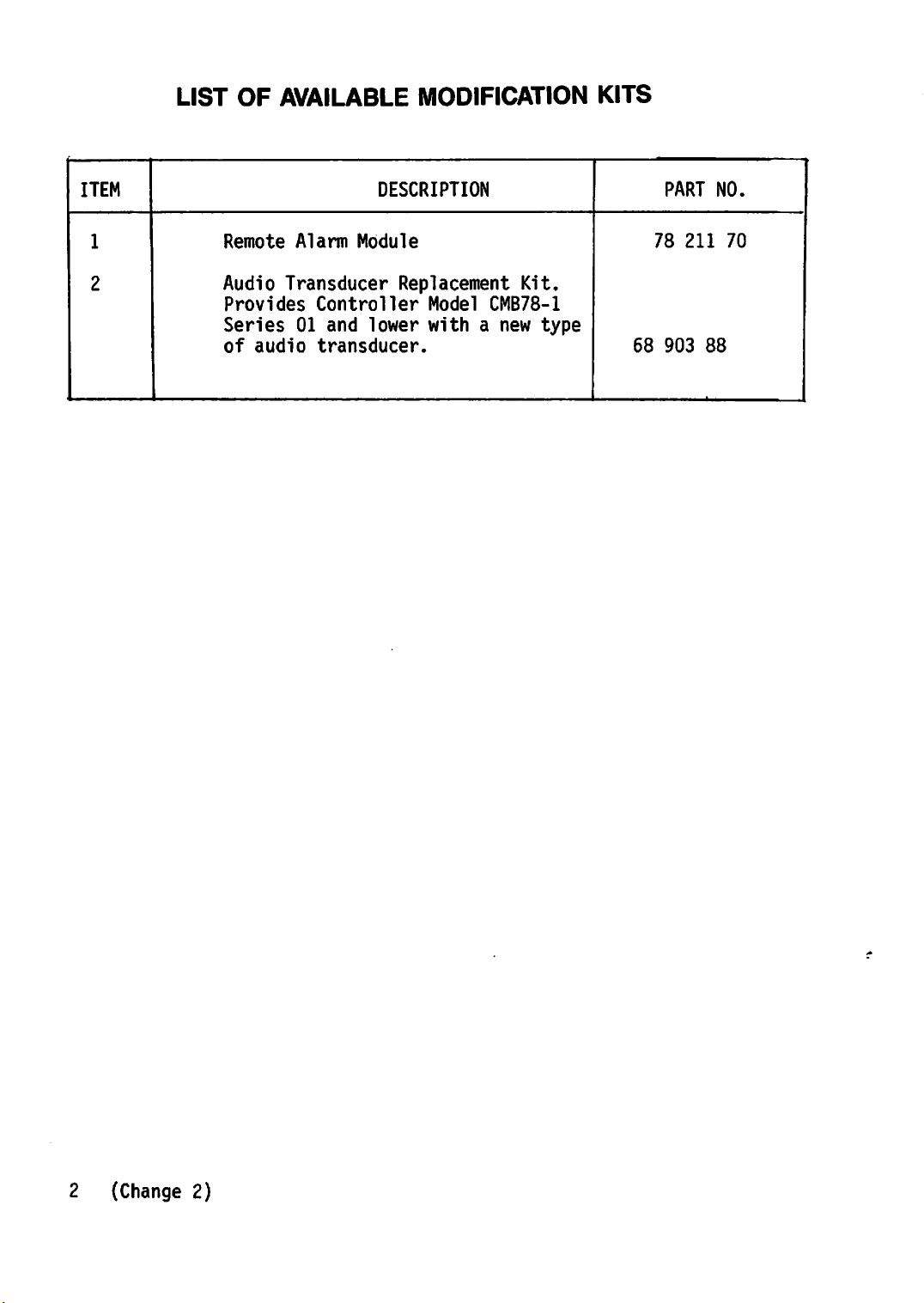
LIST
OF
AVAILABLE
MODIFICATION
KITS
ITEM
1
2
Remote
Audio
Provides
Transducer
Series
of
audio
Alarm
01 and
Module
Controller
lower
transducer.
DESCRIPTION
Replacement
Model
with
Kit.
CMB78-1
a new
type
68
PART
78
903
211
NO.
70
88
2 (Change 2)
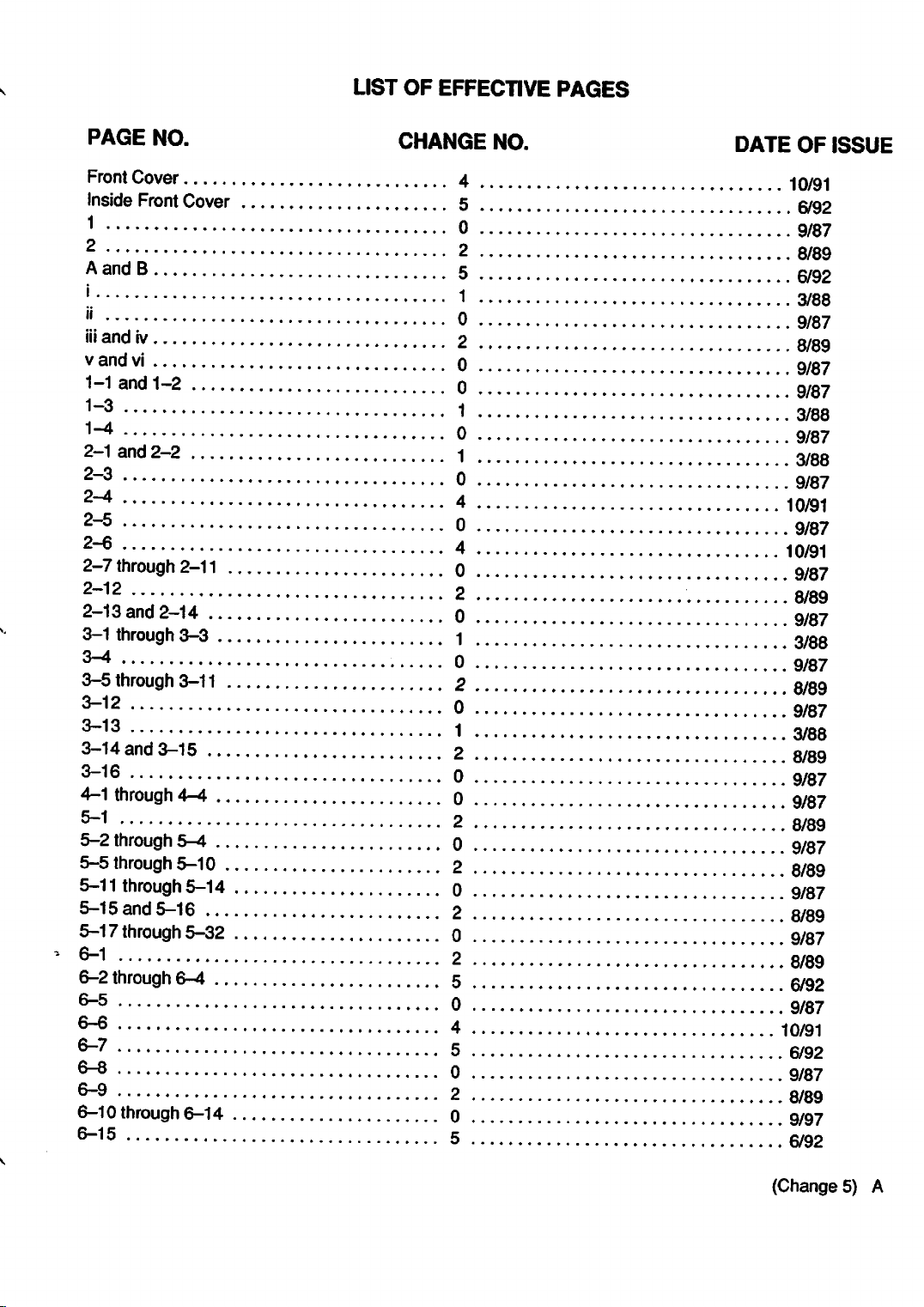
LIST
OF
EFFECTIVE
PAGES
PAGE
Front
Inside
1 0
2 2
A
!.
" 0 9/87
iij
vandvi 0
1"1
1-3 1
1-4 0
2-1 and2-2
2-3 0
2-4 4
2-5 0
2-6 4
2-7
2-12 2
2-13
3-1
3-4 • 0
3-5
3-12 0
3-13 1
3-14
3-16 0
4-1
5-1 2
5-2
5-5
5-11
5-15 and5-16 2
5-17
6-1
6-2
6-5 0
6-6 4
6-7 5
6-8 0
6-9 2
6-10
6-15 5
NO.
Cover
Front
Cover
and
B 5
and
iv
and
1"2 0
through
and
through
through
and
through
through
through
through
through
through
through
2-11
2-14 0
3-3 1
3-11
3-15 2
4-4 0
5-4 0
5-10 2
5-14 0
5-32 0
6-4 5
6-14 0 9/97
CHANGE
4
5
1
2
-,
0
2
2
NO.
DATE
OF
10/91
6/92
9/87
8/89
6/92
3/88
8/89
9/87
9/87
3/88
9/87
3/88
9/87
10/91
9/87
10/91
9/87
8/89
9/87
3/q8
9/87
8/89
9/87
3/88
8/89
9/87
9/87
8/89
9/87
8/89
9/87
8/89
9/87
8/89
6/92
9/87
10/91
6/92
9/87
8/89
6/92
ISSUE
(Change5)
A
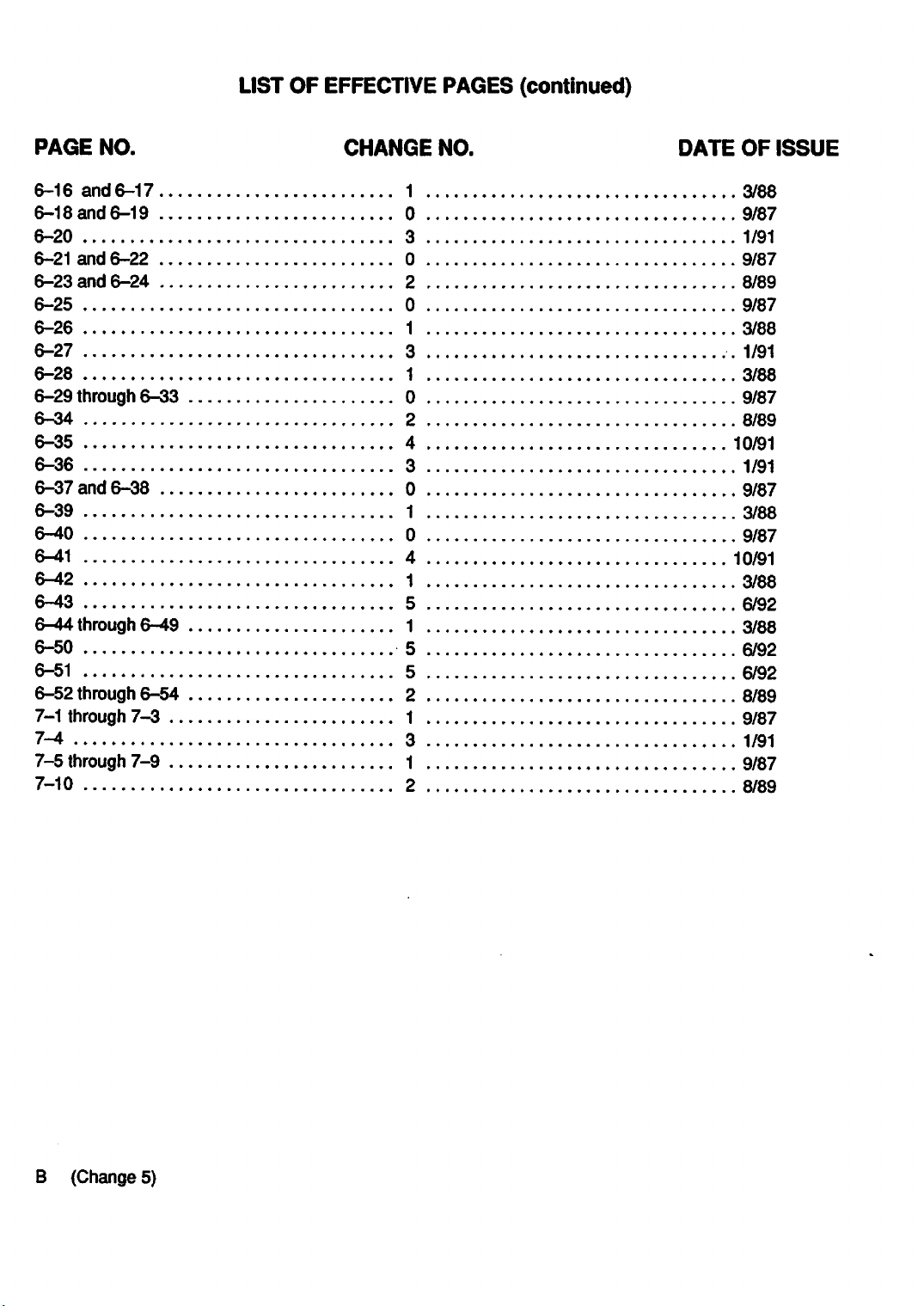
LIST
OF EFFECTIVE
PAGES
(continued)
PAGE
6-16
6-18
6-20
6-21
6-23
6-25
6-26
6-27
6-28
6-29
6-34
6-35
6-36
6-37
6-39
6-40
6-41
6-42
6-43
6-44
6-50
6-51
6-52
7-1
through
7-4
7-5
through
7-10
NO.
and
6-17
and
6-19
and
6-22
and
6-24
through
and
6-38
through
through
6-33
6-49
6-54
7-3
7-9
CHANGE
1
0
3
0
2
0
1
3
1
0 9/87
2
4
3 1/91
0
1
0
4 10/91
1
5
1 3/88
5
5
2 8/89
1 9/87
3 1/91
1 9/87
2
NO.
DATE
OF
3/88
9/87
1/91
9/87
8/89
9/87
3/88
1/91
3/88
8/89
10/91
9/87
3/88
9/87
3/88
6/92
6/92
6/92
8/89
ISSUE
B (Change 5)
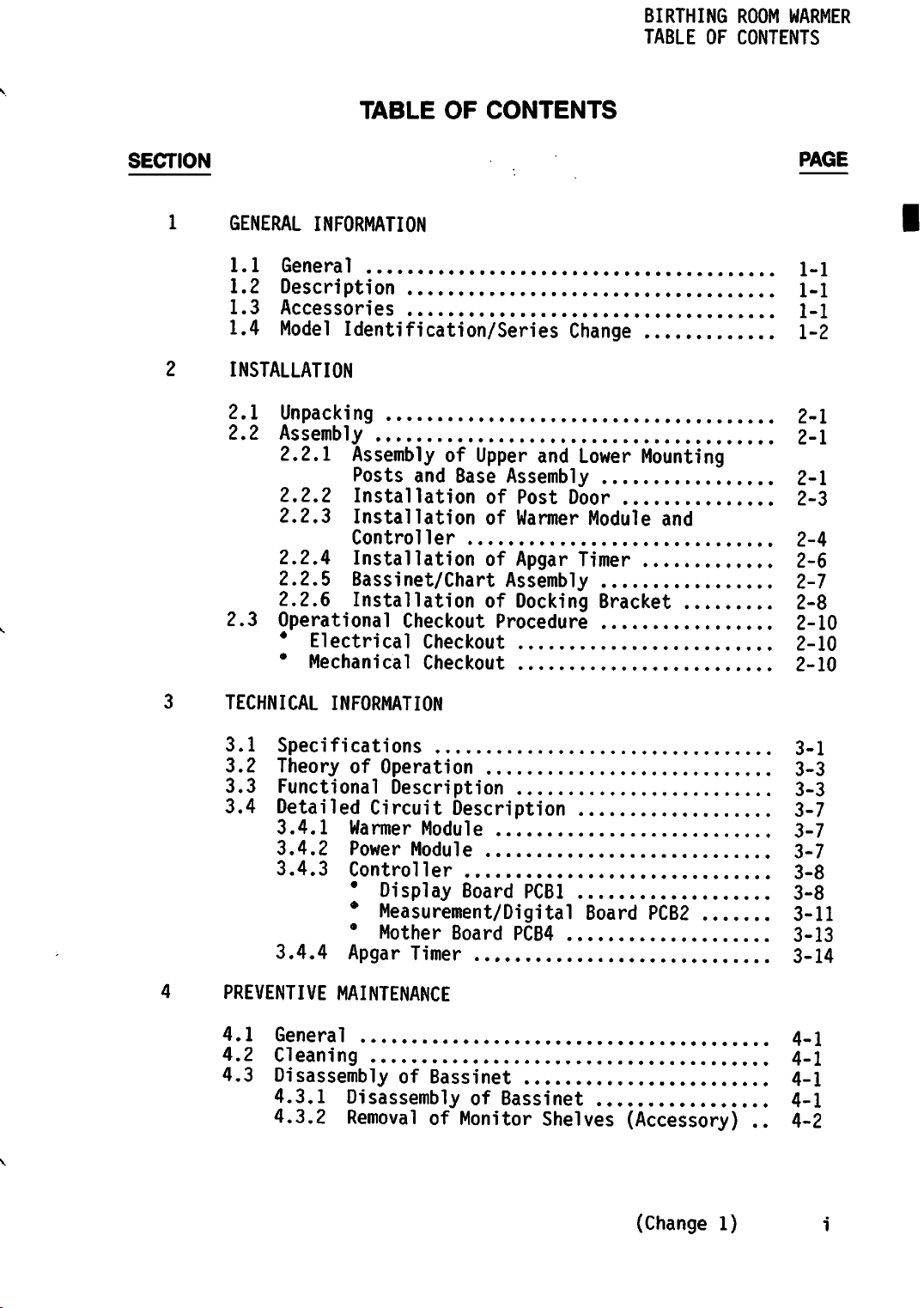
BIRTHING
TABLE OF CONTENTS
ROOM WARMER
SECTION
1 GENERAL INFORMATION
1.1
General
1.2
Description
1.3
Accessories
1.4
Model
2 INSTALLATION
2.1
2.2
Unpacking
Assembly
2.2.1
2.2.2
2.2.3
2.2.4
2.2.5
2.2.6
2.3
Operational
*
Electrical
•
Mechanical
TABLE
Identification/Series
AssemblyofUpper
Posts
Installation
Installation
Control
InstallationofApgar
Bassinet/Chart
OF
CONTENTS
Change
and
Lower
and
Base
Assembly
of
Post
of Warmer
ler 2-4
Assembly
Door
Timer
InstallationofDocking
Checkout
Checkout
Checkout
Procedure
Mounting
Module
Bracket
PAGE
1-1
1-1
1-1
1-2
2-1
2-1
2-1
2-3
and
2-6
2-7
2-8
2-10
2-10
2-10
3 TECHNICAL INFORMATION
3.1
3.2
3.3
3.4
4 PREVENTIVE MAINTENANCE
4.1
4.2
4.3
Specifications
Theory
Functional
Detailed
3.4.1
3.4.2
3.4.3
3.4.4
of
Operation
Description
Circuit
Warmer
Power
Controller
*
*
*
Apgar
Module
Module
Display
Measurement/Digital
Mother
Timer
General
Cleaning
DisassemblyofBassinet
4.3.1
4.3.2
DisassemblyofBassinet
RemovalofMonitor
Description
Board
Board
PCB1
PCB4
Shelves
Board
PCB2
(Accessory)..4-2
3-1
3-3
3-3
3-7
3-7
3-7
3-8
3-8
3-11
3-13
3-14
4-1
4-1
4-1
4-1
(Change
1)
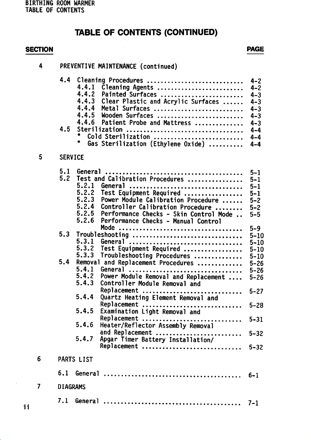
BIRTHING ROOM
TABLE OF CONTENTS
WARMER
SECTION
4
5 SERVICE
TABLE
PREVENTIVE
4.4
4.5 Sterilization 4-4
5.1
5.2
5.3
5.4
Cleaning
4.4.1
4.4.2
4.4.3
4.4.4
4.4.5 Wooden
4.4.6
•
•
General
Test
5.2.1
5.2.2
5.2.3 Power Module Calibration Procedure 5-2
5.2.4
5.2.5
5.2.6
Troubleshooting
5.3.1
5.3.2
5.3.3
Removal
5.4.1
5.4.2
5.4.3 Controller
5.4.4
5.4.5
5.4.6
5.4.7
OF
CONTENTS
MAINTENANCE
Procedures
Cleaning
Painted
Clear
Metal
Patient
Cold
Gas
Sterilization
Sterilization
and
Calibration
General
Test
Controller
Performance
Performance
Mode
General
Test
Agents
Surfaces
Plastic
Surfaces
Surfaces
Probe
Equipment
Equipment
Troubleshooting
and
Replacement
General
Power
Replacement
Quartz
Repl
Module
Heating
acement
Examination
Replacement
Heater/Reflector
and
Repl
acement
Apgar
Repl
Timer
acement
(CONTINUED)
(continued)
and
Acrylic
and
Mattress
(Ethylene
Procedures
Required
Calibration
Checks-Skin
Checks-Manual
Required
Procedures
Procedures
Removal
Module
Removal
Element
Light
Removal
Assembly
Battery
Procedure
and
Removal
Installation/
Surfaces
Oxide)
Control
Control
Mode
Replacement
and
and
and
Removal
..
PAGE
4-2
4-2
4-3
4-3
4-3
4-3
4-3
4-4
4-4
5-1
5-1
5-1
5-1
5-2
5-5
5-9
5-10
5-10
5-10
5-10
5-26
5-26
5-26
5-27
5-28
5-31
5-32
5-32
6 PARTS LIST
6.1
7 DIAGRAMS
7.1
ii
General
General
6-1
7_1
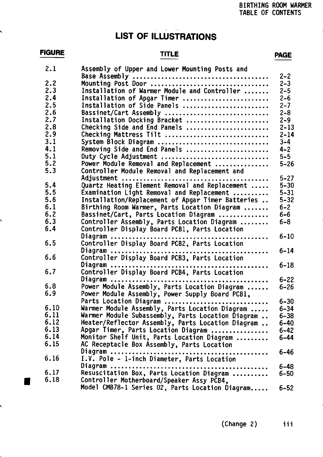
BIRTHING
TABLE
OF CONTENTS
ROOM
WARMER
FIGURE
2.
.1
.2
2,
2.
.3
2,
.4
2.
.5
.6
2.
2.
.7
.8
2,
2,
.9
3.
.1
4,
,1
5,
.1
5,
.2
5.
.3
,4
5,
5.
,5
,6
5,
6,
,1
6.
,2
6.
.3
,4
6.
6.5
6.6
6.7
6.8
6.9
6.10
6.11
6.12
6.13
6.14
6.15
6.16
6.17
6.18
LIST
Assembly
Base
Mounting
Installation
Installation
Installation
Bassinet/Cart
Installation
Checking
Checking
System
Removing
Duty
Power
Controller
Adjustment
Quartz
Examination
Installation/ReplacementofApgar
Birthing
Bassinet/Cart,
Controller
Controller
Diagram
Controller
Diagram
Controller
Diagram
Controller
Diagram
Power
Power
Parts
Warmer
Warmer
Heater/Reflector
Apgar
Monitor
AC
Receptacle
Diagram
I.V.
Diagram 6-48
Resuscitation
Controller
Model
of
Assembly
Post
Side
Mattress
Block
Side
Cycle
Module
Heating
Room
Module
Module
Location
Module
Module
Timer,
Shelf
Pole-1-inch
CMB78-1
OF
ILLUSTRATIONS
TITLE
Upper
of
of
of
Docking
Diagram
Adjustment
Module
Light
Assembly,
Display
Display
Display
Display
Assembly,
Assembly,
Parts
Motherboard/Speaker
and
Lower
Mounting
Door
Warmer
Apgar
Side Panels 2-7
Module and
Timer
Assembly
Bracket
and
End
Panels
Tilt
and
End
Panels
Removal
Element
Warmer,
Parts
Diagram
Assembly,
Subassembly,
Unit,
Box
Box,
and
Replacement
Removal
Removal
Removal
Parts
Location
Parts
Board
Board
Board
Board
PCB1,
PCB2,
PCB3,
PCB4,
Parts
Power
Parts
Assembly,
Location
Parts
Assembly,
Diameter,
Parts
Location
and
Replacement
and
and
Replacement
Location
Diagram
Location
Parts
Parts
Parts
Parts
Location
Supply
Location
Parts
Parts
Diagram
Location
Parts
Parts
Assy
Series
02,
Parts
Location
Posts
Controller
Replacement
Timer
Batteries
Diagram
Diagram
Location
Location
Location
Location
Diagram
Board
Diagram
Location
Location
Diagram
Location
Location
Diagram
PCB4,
Diagram
and
and
PCB1,
Diagram
Diagram
..
..
..
PAGE
2-2
2-3
2-5
2-6
2-8
2-9
2-13
2-14
3-4
4-2
5-5
5-26
5-27
5-30
5-31
5-32
6-2
6-6
6-8
6-10
6-14
6-18
6-22
6-26
6-30
6-34
6-38
6-40
6-42
6-44
6-46
6-50
6-52
(Change
2)
iii
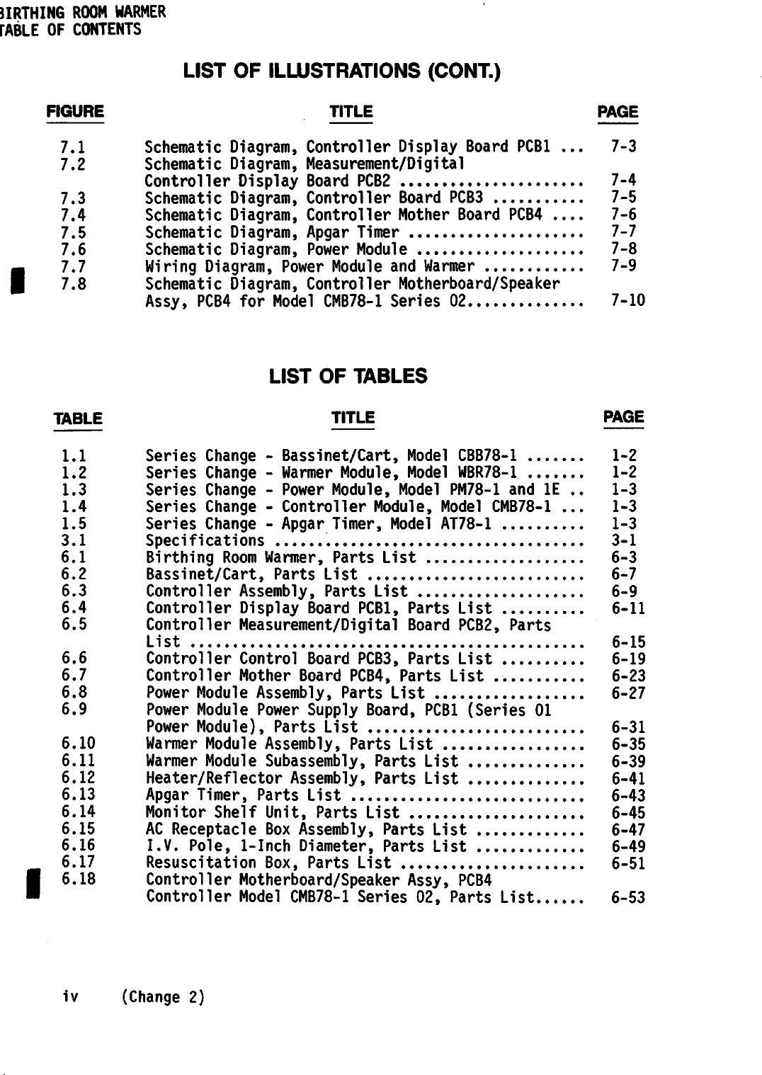
LIST
OF ILLUSTRATIONS (CONT.)
17.7
I
FIGURE
7.1
7.2
7.3
7.4
7.5
7.6
7.8
TABLE
1.1
1.2
1.3
1.4
1.5
3.1
6.1
6.2
6.3
6.4
6.5
6.6
6.7
6.8
6.9
6.10
6.11
6.12
6.13
6.14
6.15
6.16
6.17
6.18
TITLE
Schematic
Schematic
Controller
Schematic
Schematic
Schematic
Schematic
Wiring
Schematic
Assy,
Series
Series
Series
Series
Series
Specifications
Birthing
Bassinet/Cart,
Controller
Controller
Controller
List 6-15
Controller
Controller
Power
Power
Power
Warmer
Warmer
Heater/Reflector
Apgar
Monitor
AC
Receptacle
I.V.
Resuscitation
Controller
Controller
Diagram,
Diagram,
Display
Diagram,
Diagram,
Diagram,
Diagram,
Diagram,
Diagram,
PCB4
for
Change-Bassinet/Cart,
Change-Warmer
Change-Power
Change-Controller
Change-Apgar
Room
Assembly,
Display
Controller
Measurement/Digital
Board
PCB2
Controller
Controller
Apgar
Power
Power
Timer
Module
Module
Controller
Model
LIST
Warmer,
Parts
CMB78-1
OF
TITLE
Module,
Module,
Timer,
Parts
List
Parts
Board
TABLES
PCBl,
Measurement/Digital
Control
Mother
Module
Module
Module),
Module
Module
Timer,
Shelf
Pole,
1-Inch
Assembly,
Power
Parts
Board
Board
PCB3,
PCB4,
Parts
Supply
Parts
Assembly,
List
Parts
Subassembly,
Assembly,
List
Unit,
Box
Box,
Parts
Assembly,
Diameter,
Parts
List
Motherboard/Speaker
Model
CMB78-1
Series
Display
Board
Mother
and
Warmer
Board
PCB3
Board
Motherboard/Speaker
Series
Model
Model
Model
Module,
Model
List
List
Parts
List
Board,
List
Parts
Parts
List
Parts
Parts
Assy,
Model
AT78-1
Parts
Board
Parts
PCBl
List
List
List
List
02,
02
CBB78-1
WBR78-1
PM78-1
CMB78-1
List
PCB2,
List
List
(Series
PCB4
Parts
PCBl
PCB4
and
Parts
List
....
IE
01
...
..
...
PAGE
7-3
7-4
7-5
7-6
7-7
7-8
7-9
7-10
PAGE
1-2
1-2
1-3
1-3
1-3
3-1
6-3
6-7
6-9
6-11
6-19
6-23
6-27
6-31
6-35
6-39
6-41
6-43
6-45
6-47
6-49
6-51
6-53
iv
(Change
2)

BIRTHING
TABLE
OF CONTENTS
ROOM
WARMER
CHART
5.1
5.2
5.3
Controller
Warmer
Power
Module
Module
LIST
OF
FLOWCHARTS
TITLE
Module
Troubleshooting
Troubleshooting
Troubleshooting
PAGE
5-12
5-21
5-23

BIRTHING
TABLE
OF
ROOM
WARMER
CONTENTS
vi
(This
pageisintentionally
left
blank.)
BIRTHING
GENERAL
ROOM
WARMER
INFORMATION
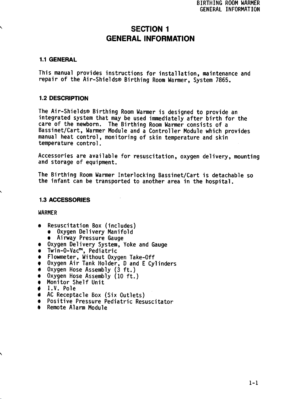
1.1
GENERAL
This
The
care
manual
provides
repairofthe
1.2
DESCRIPTION
Air-Shields®
integrated
of
system
the
newborn.
Air-Shields®
Bassinet/Cart,
manual
temperature
Accessories
and
The
the
heat
storage
Birthing
infant
can
control,
control.
are
of
Room
SECTION
GENERAL
instructions
Birthing
Birthing
that
Warmer
Room
may
be
The
Birthing
Module
Warmerisdesignedtoprovide
used
andaController
monitoringofskin
available
equipment.
Warmer
be
transportedtoanother
for
resuscitation,
Interlocking
1
INFORMATION
for
installation,
Room
Warmer,
immediately
Room
Warmer
Module
temperature
oxygen
after
consistsofa
maintenance
System
birth
which
and
delivery,
Bassinet/Cartisdetachable
area
in
the
hospital.
7865.
an
for
provides
skin
and
the
mounting
so
1.3
ACCESSORIES
WARMER
s
Resuscitation
•
Oxygen
•
Airway
e
Oxygen
«
Twin-0-Vac™,
•
Flowmeter,
t
Oxygen
9
Oxygen
•
Oxygen
•
Monitor
• I.V.
0
AC
§ Positive Pressure Pediatric Resuscitator
• Remote Alarm Module
Delivery
Air
Hose
Hose
Shelf
Pole
Receptacle
Box
Delivery
Pressure
System,
Pediatric
Without
Tank
Holder,DandECylinders
Assembly
Assembly
Unit
Box
(includes)
Manifold
Gauge
Yoke
Oxygen
(Six
Take-Off
(3
ft.)
(10
ft.)
Outlets)
and
Gauge
1-1
BIRTHING ROOM WARMER
GENERAL INFORMATION
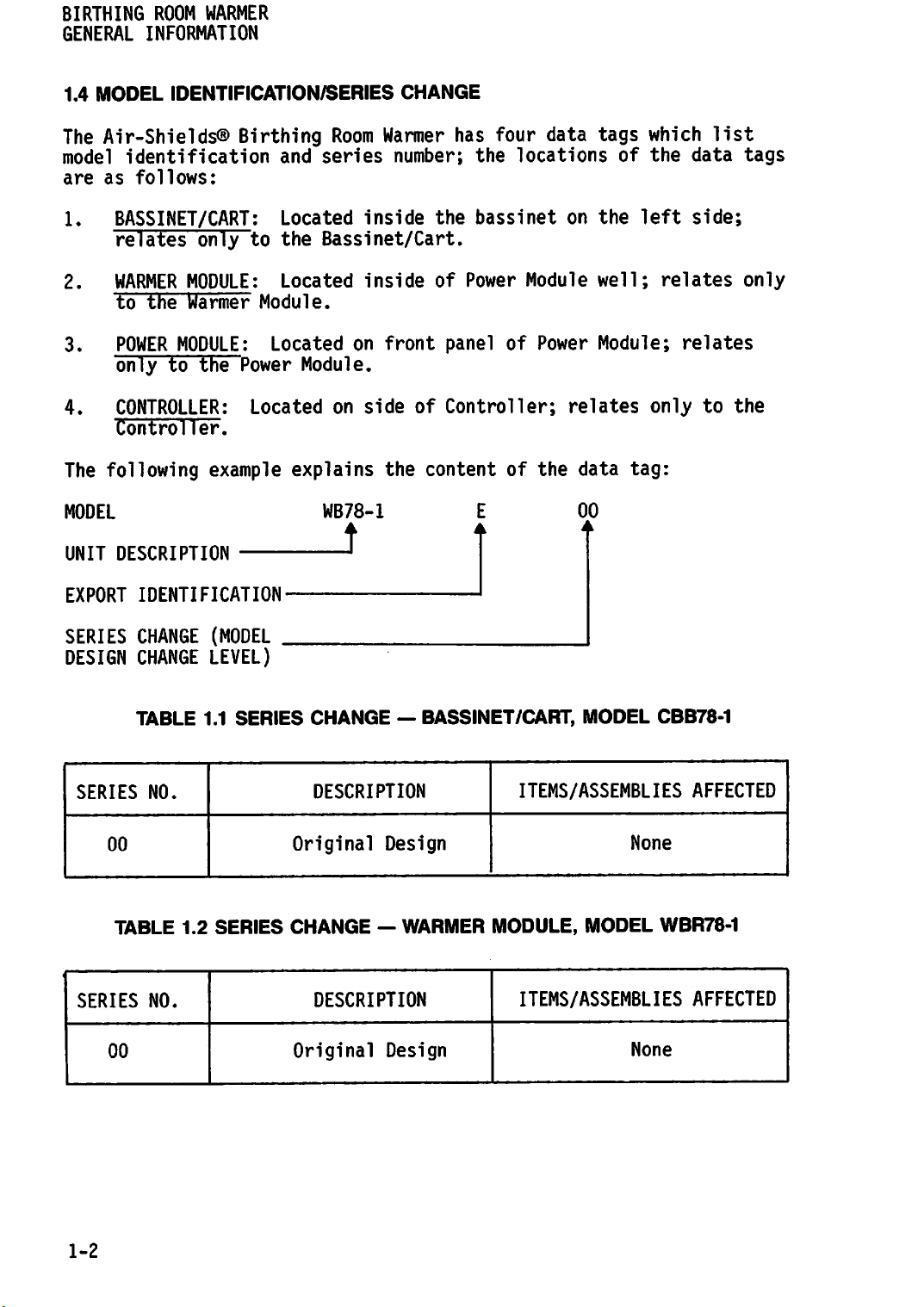
1.4
MODEL
The
Air-Shields®
model
are
as
1.
BASSINET/CART:
relates
2.
WARMER
to the
3.
POWER
only
4.
CONTROLLER:
Controller.
The
following
IDENTIFICATION/SERIES
Birthing
identification
follows:
only
MODULE:
Warmer
to
MODULE:
to
the
Power
Located
example
and
Located
the
Located
Module.
Located
Module.
explains
CHANGE
Room
series
inside
Warmer
number;
has
the
Bassinet/Cart.
on
inside
on
side
of
front
the
panel
of
Controller;
contentofthe
four
the
locations
bassinet
Power
Module
of
data
on
Power
relates
tags
of the
the
well;
Module;
data
which
left
only
tag:
list
data
side;
relates
relates
to
tags
only
the
MODEL
UNIT
DESCRIPTION
EXPORT IDENTIFICATION
SERIES
DESIGN
SERIES
SERIES
CHANGE
CHANGE
TABLE
00
TABLE
NO.
NO.
1.1
1.2
(MODEL
LEVEL)
SERIES
SERIES
WB78-1
.J
.
CHANGE
DESCRIPTION
Original
CHANGE-WARMER
DESCRIPTION
—
BASSINET/CART,
Design
00
•
MODEL
ITEMS/ASSEMBLIES
None
MODULE, MODEL
ITEMS/ASSEMBLIES
CBB78-1
AFFECTED
WBR78-1
AFFECTED
1-2
00
Original
Design
None
BIRTHING
GENERAL
ROOM
WARMER
INFORMATION
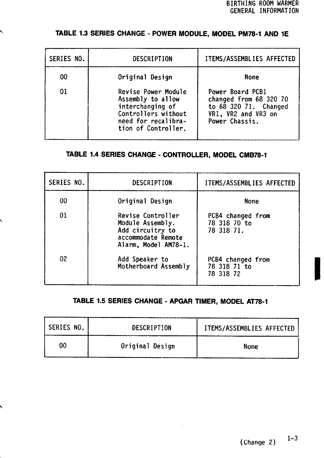
TABLE 1.3
SERIES
00
01
TABLE 1.4
SERIES
00
NO.
NO.
SERIES
SERIES
CHANGE - POWER MODULE, MODEL PM78-1 AND 1E
DESCRIPTION
Original
Revise
Assembly
interchanging
Controllers
need
tion of Controller.
Design
Power
to allow
for
recalibra-
Module
of
without
ITEMS/ASSEMBLIES AFFECTED
None
Power
changed
to 68 320
VR1, VR2 and VR3 on
Power
Board
PCBl
from
71.
Chassis.
68
320
Changed
70
CHANGE - CONTROLLER, MODEL CMB78-1
DESCRIPTION
Original
Design
ITEMS/ASSEMBLIES AFFECTED
None
01
02
SERIES
00
TABLE 1.5
NO.
Revise
Module
Add
circuitry
accommodate
Alarm,
Add
Speaker
Motherboard
SERIES
CHANGE -
DESCRIPTION
Original
Controller
Assembly.
to
Remote
Model
AM78-1.
to
Assembly
APGAR
Design
PCB4
78
78
PCB4
78
78
changed
318
70 to
318
71.
changed
318
71 to
318
72
from
from
TIMER, MODEL AT78-1
ITEMS/ASSEMBLIES AFFECTED
None
I
(Change 2)
1-3

BIRTHING
GENERAL
ROOM
WARMER
INFORMATION
1-4
(This
pageisintentionally
left
blank.)
BIRTHING
ROOM
WARMER
INSTALLATION
2.1
UNPACKING
When
or
materials.
The
following
removing
otherwise
Birthing
items:
Warmer
Upper
Lower
Base
Docking
Controller
Bassinet/Cart
Mattress
Mattress
Ballast
Casters
Patient
Handle
Apgar
Post
Bumpers
End and Side Panels
Module
Mounting
Mounting
Assembly
Timer
Door
the
equipment
damage
Room
Warmer
Bracket
Assembly
Tray
for
Cart
Probe
INSTALLATION
from
unprotected
is
shippedincartons
Assembly
Post
Post
and
SECTION
the
surfaces;
Power
Module
2
cartons,
remove
use
all
which
care
packing
contain
not
to
scratch
the
2.2
ASSEMBLY
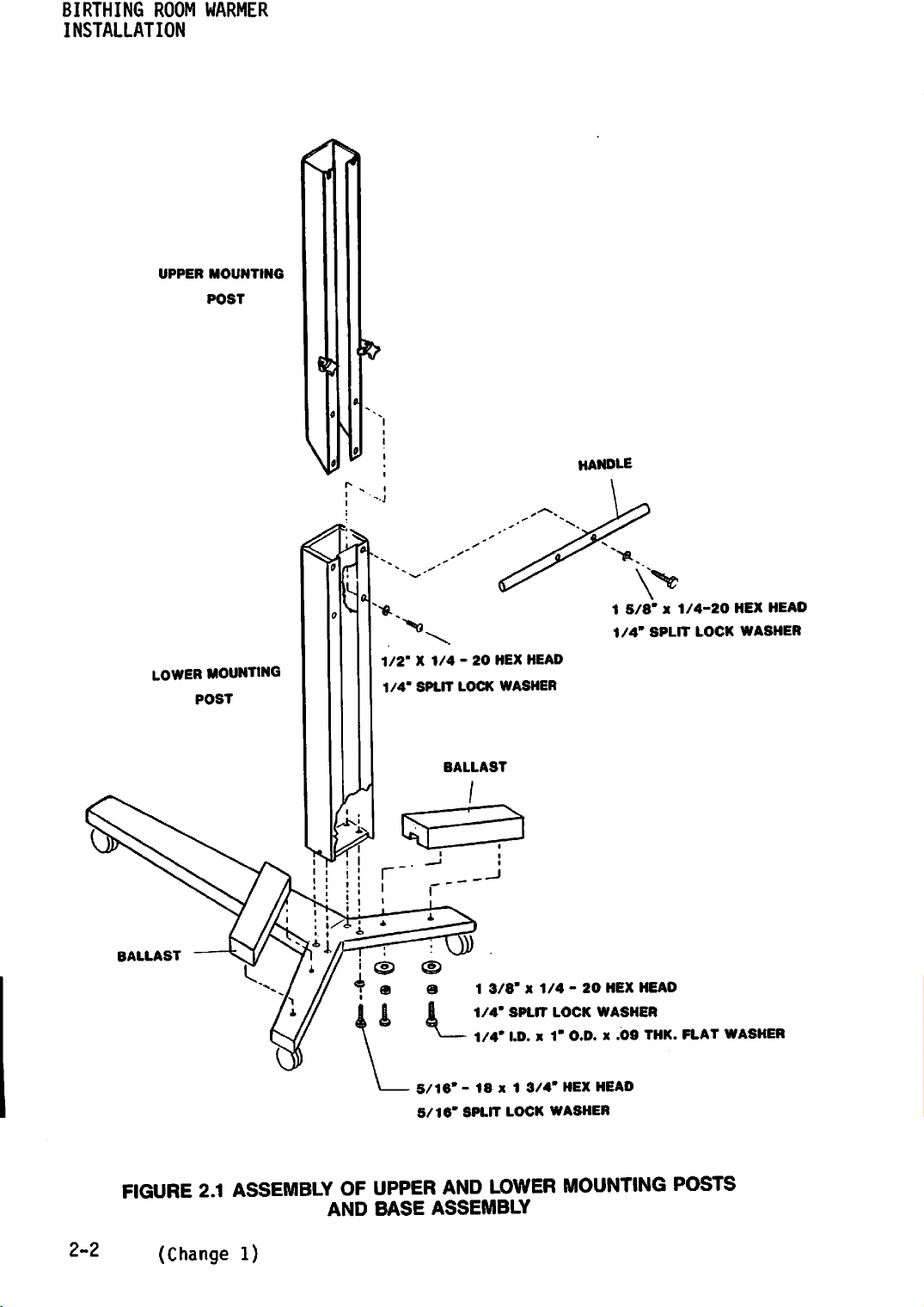
2.2.1 ASSEMBLY OF UPPER AND LOWER
A.
B.
C
REFERTOFIGURE
Assembly
REFER
mounting bolts and
TO
using
FIGURE
REFERTOFIGURE
Lower
and
Mounting
lockwashers
2.1
the
2.1
2.1
Post
supplied.
and
four
and
lockwashers.
and
and
MOUNTING
mount
the
mounting
mount
mount
the
the two
the
handle
POSTS AND BASE ASSEMBLY
Lower
bolts
Upper
using
Mounting
and
lockwashers
weights
Mounting
the
Postonthe
using
Post
four
mounting
(Change
supplied.
the
four
on
the
1)
Base
screws
2-1
BIRTHING
ROOM
INSTALLATION
UPPER
WARMER
MOUNTING
POST
HANDLE
BALLAST
1/2"X1/4-20
1/4"
SPLIT
LOCK
5/16"-18
5/16"
SPLIT
HEX HEAD
WASHER
1
3/8"x1/4-20
1/4"
SPLIT
1/4"
I.D. x 1" O.D. x
x 1
3/4"
LOCK
WASHER
LOCK
HEX
1
5/8"x1/4-20
1/4"
HEX
HEAD
WASHER
.09
HEAD
SPLIT
THK.
LOCK
FLAT
HEX HEAD
WASHER
WASHER
2-2
FIGURE
(Change 1)
2.1
ASSEMBLY
OF
AND
UPPER
BASE
AND
LOWER
ASSEMBLY
MOUNTING
POSTS
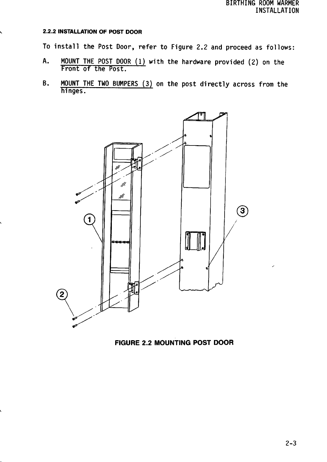
2.2.2
To
install
A.
B.
INSTALLATION
the
MOUNT
Front
MOUNT
hinges.
THE
of
THE
OF
Post
POST
the
TWO
POST
DOOR
Door,
DOOR
Post.
BUMPERS
refertoFigure
(1)
with
the
hardware
(3)
on
the
post
^Sl
2.2
and
provided
directly
BIRTHING
ROOM
WARMER
INSTALLATION
proceedasfollows:
(2)
on
the
across
from
the
FIGURE
2.2
MOUNTING
POST
DOOR
2-3
BIRTHING
INSTALLATION
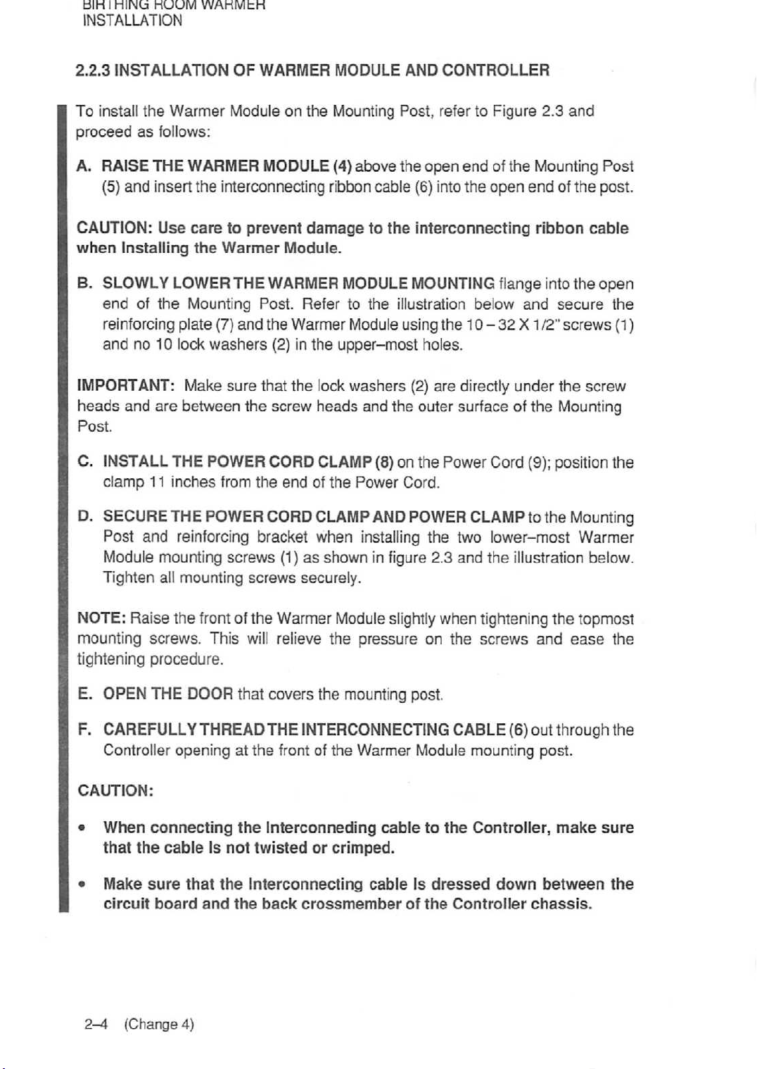
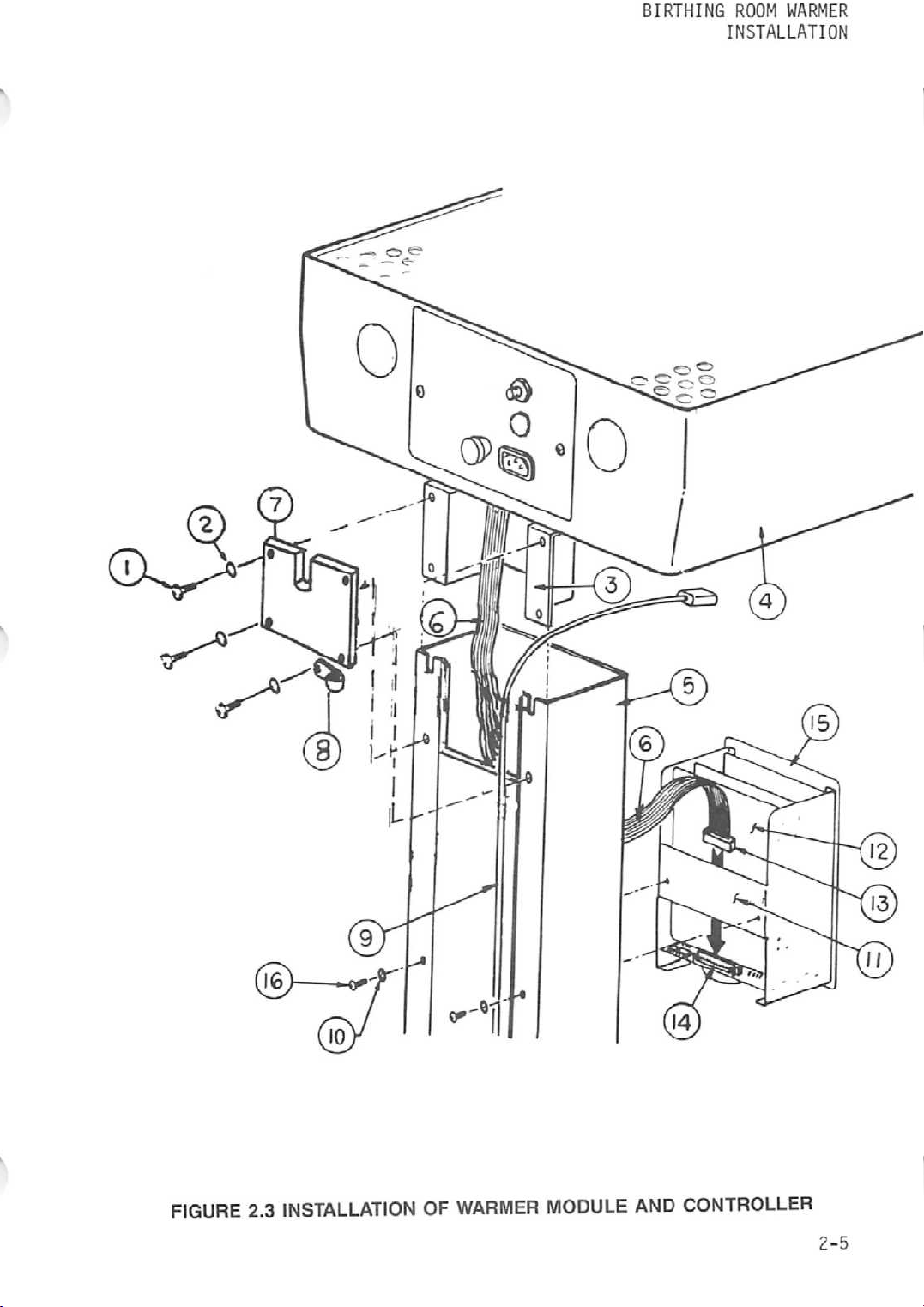
2.2.3
INSTALLATION
ROOM
WARMER
OF
WARMER
MODULE
AND
CONTROLLER
To install
proceed
A.
CAUTION:
when
B.
IMPORTANT: Make
heads
Post.
the
Warmer
as
follows:
RAISE
(5)
SLOWLY
end
THE
and
insert
Use
Installing
LOWER THE WARMER
of
the
WARMER
the
interconnecting ribbon
caretoprevent
the
Warmer
Mounting Post. Refer to the illustration below
reinforcing plate (7)
and
no 10 lock
and
are
washers
between
Module on
MODULE (4)
and
the
(2) in the
sure
that
the
screw
the
Mounting Post, refer to Figure
above
damagetothe
Module.
MODULE
the
open
endofthe
cable
(6) into
the
open
interconnecting
MOUNTING flange intothe open
Warmer Module using the 10 - 32 X
the
upper-most
lock
washers
heads
and
the
holes.
(2)
outer
are
directly
surfaceofthe
2.3
Mounting
endofthe
ribbon
and
secure
112"
under
and
cable
screws
the
screw
Mounting
C. INSTALL THE POWER CORD CLAMP (8) on the Power Cord (9); position
clamp
11
inches
from
the
endofthe
Power
Cord.
">
Post
post.
the
(1)
the
D. SECURE THE POWER CORD CLAMP AND POWER CLAMP to the Mounting
Post and reinforcing bracket when installing the two lower-most Warmer
Module mounting screws (1) as shown in figure 2.3 and the illustration below.
Tighten all mounting
screws
securely.
NOTE: Raise the frontofthe Warmer Moduleslightlywhen tightening the topmost
mounting screws. This
will
relieve
the
pressure
on
the
screws
and
ease
the
tightening procedure.
E. OPEN THE DOOR that covers the mounting post.
F. CAREFULLY THREAD THE INTERCONNECTING CABLE (6) out through the
Controller opening at
CAUTION:
•
•
When
that
Make
circuit
connecting
the
cableIsnot
sure
that
board
and
the
front of the Warmer Module mounting post.
the
Interconneding
twisted
the
Interconnecting
the
back
or
crimped.
crossmember
cabletothe
cableIsdressed
of
the
Controller
Controller,
down
chassis.
make
between
sure
the
2-4
(Change
4)
BIRTHING
ROOM
WARMER
INSTALLATION
FIGURE
2.3
INSTALLATIONOFWARMER
MODULE
AND
CONTROLLER
2-5
BIRTHING
INSTALLATION
ROOM
WARMER
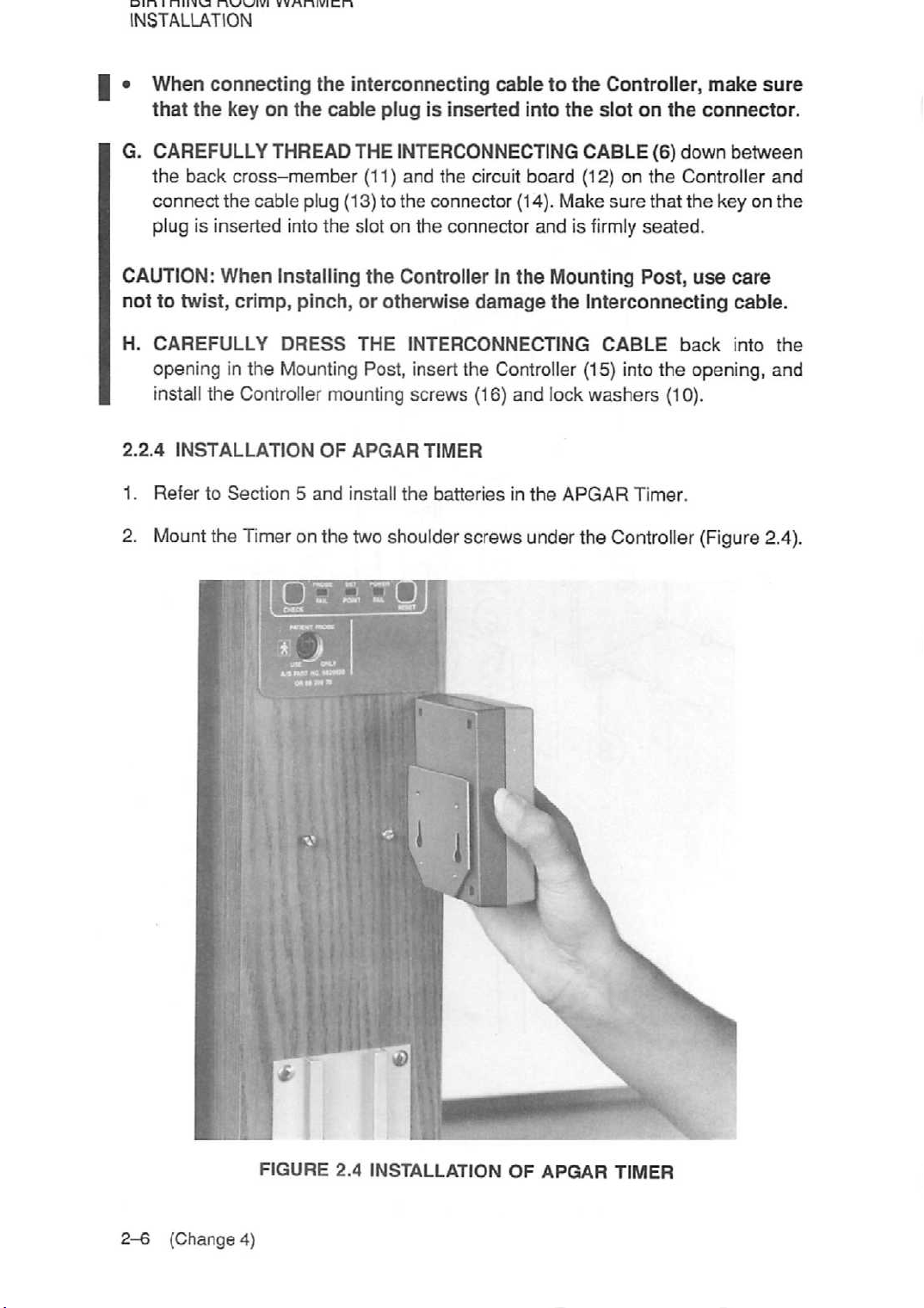
I • When connecting the interconnecting cable to the Controller,
that
the
key
on
the
cable
G.
CAREFULLY
the
back
connect
THREAD
cross-member
the
cable plug (13) to
plug is inserted into the slot on the connector
CAUTION:
nottotwist,
H.
CAREFULLY
When
crimp,
Installing
pinch,orotherwise
DRESS
opening in the Mounting Post, insert the Controller (15) into the opening, and
install the Controller mounting screws (16) and lock
2.2.4
1.
2.
INSTALLATION
RefertoSection5and
Mount
the Timer on the two shoulder screws under the Controller (Figure 2.4).
OF
plugisinserted
THE
INTERCONNECTING
into
the
CABLE
(11) and the circuit board (12) on
the
connector (14). Make
andisfirmly
the
Controller In
THE
INTERCONNECTING
the
damage
Mounting
the
Interconnecting
washers
APGAR
install
TIMER
the
batteriesinthe
APGAR
slot
sure
CABLE
Timer.
on
the
(6)
down
the
that
seated.
Post,
back
(10).
Controller
the
make
connector.
between
key on
use
care
cable.
into
sure
and
the
the
2-6
(Change
FIGURE
4)
2.4
INSTALLATION
OF
APGAR
TIMER
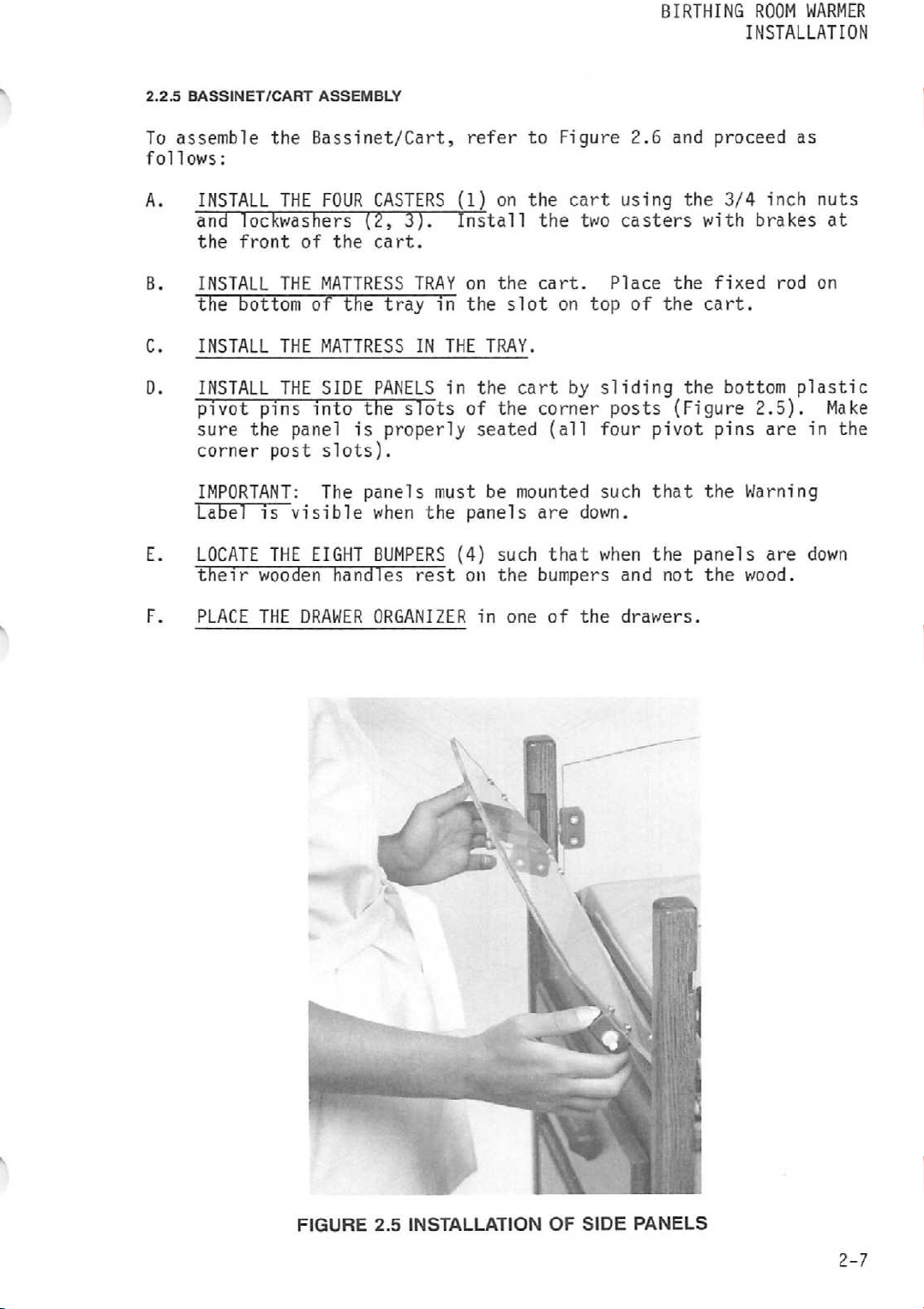
2.2.5
BASSINET/CART
To
assemble
follows:
ASSEMBLY
the
Bassinet/Cart,
refer
to
Figure
BIRTHING
2.6 and
ROOM WARMER
INSTALLATION
proceed
as
A.
B.
C.
D.
E.
F.
INSTALL
and
the
INSTALL
THE
FOUR
lockwashers
front
of
THE
the
MATTRESS
the bottom of the
INSTALL
INSTALL
pivot
sure
corner
IMPORTANT:
Label
LOCATE
their
PLACE
THE
THE
pins
the
post
is
THE
wooden
THE
MATTRESS
SIDE
into
panel
slots).
The
visible
EIGHT
handles
DRAWER
is
CASTERS
(2,
3).
cart.
TRAY
tray
IN
PANELS
the
slots
properly
panels
when the
BUMPERS
rest
ORGANIZER
(1)
on
Install
on the cart.
in
the
slot
THE
TRAY.
in
the
of
the
seated
must
be
panels
(4)
such
on
the
in
one
the
cart
the
two
on top of the
cart
by
corner
(all
mounted
are
down.
that
bumpers
of
the
using
casters
Place
sliding
posts
four
such
when
and not the
drawers.
the
(Figure
pivot
that
the
the
with
fixed
cart.
the
pins
the
panels
3/4
inch
brakes
bottom
2.5).
are
Warning
are
wood.
nuts
rod on
plastic
in
down
at
Make
the
FIGURE
2.5
INSTALLATION
OF
SIDE
PANELS
2-7
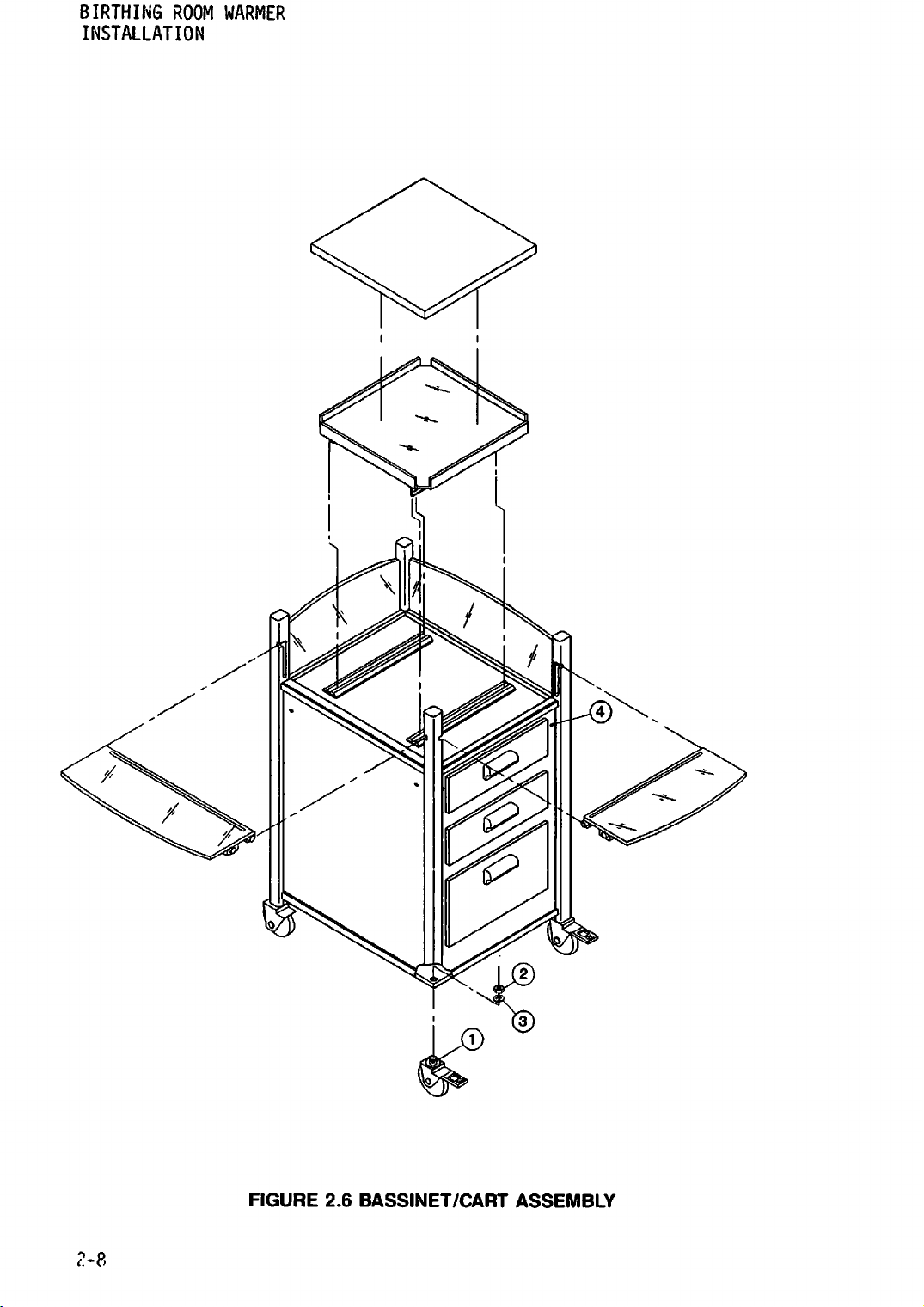
BIRTHING
INSTALLATION
ROOM
WARMER
FIGURE
2.6
BASSINET/CART
ASSEMBLY
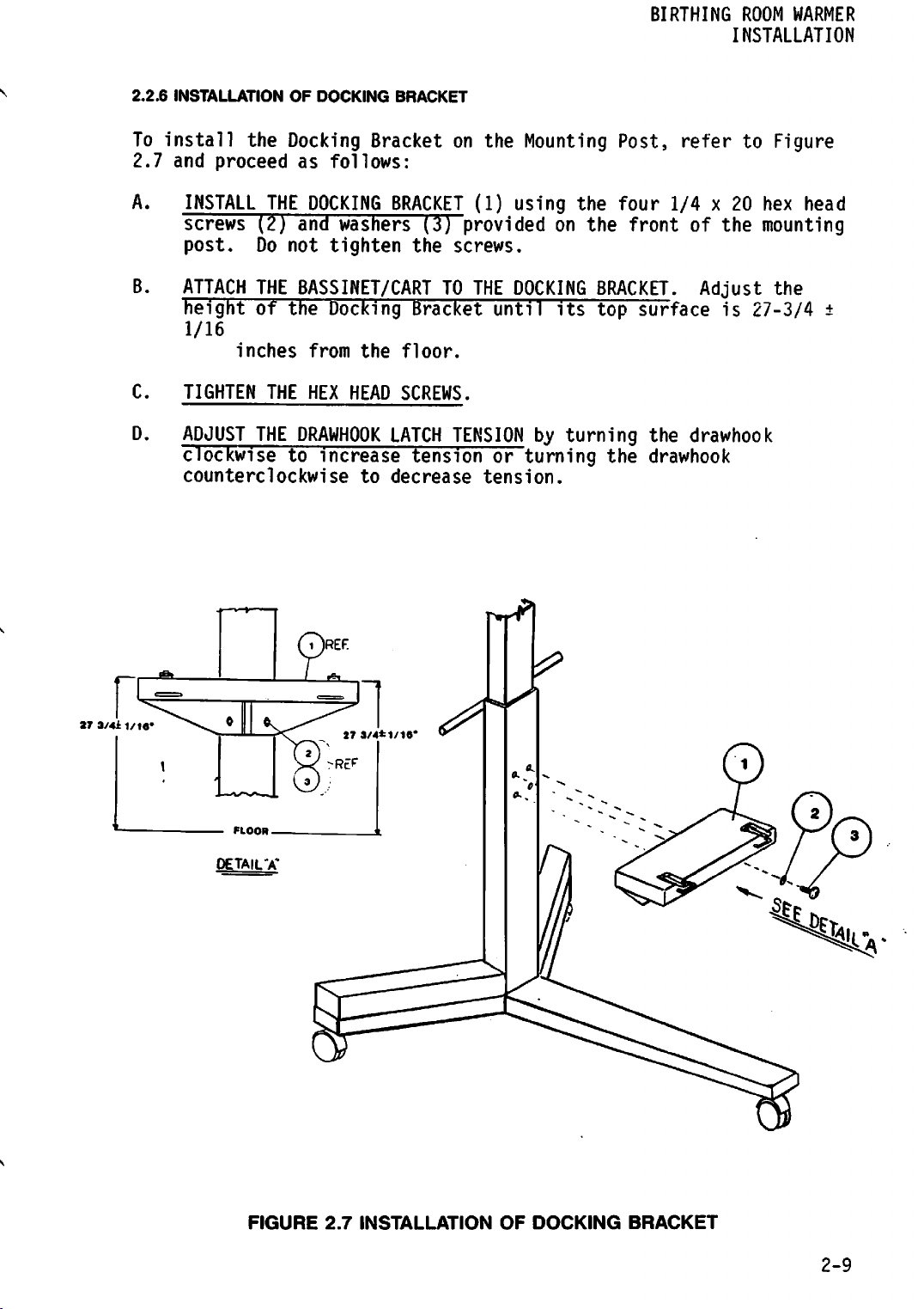
2.2.6
To
install
2.7
INSTALLATION
the
and
proceed
OF
DOCKING
Docking
as
follows:
BRACKET
Bracketonthe
Mounting
BIRTHING
Post,
ROOM
WARMER
INSTALLATION
refertoFigure
A.
B.
C.
D.
INSTALL
screws
post.
ATTACH
height
1/16
TIGHTEN THE HEX HEAD SCREWS.
ADJUST
clockwise
counterclockwise to decrease tension.
THE
DOCKING
(2)
and
washers
Do
not
tighten
THE
BASSINET/CARTTOTHE
of
the
Docking
inches from the floor.
THE
DRAWHOOK
to
increase
BRACKET
(3)
the
Bracket
LATCH
tension
(1)
using
providedonthe
the
four
front
screws.
DOCKING
until
its
BRACKET.
top
TENSIONbyturning
or
turning
r»rr
the
1/4x20
of
Adjust
surface
the
drawhook
drawhook
the
is
27-3/4
hex
head
mounting
the
±
27
3/4il/1««
FIGURE
2.7
INSTALLATION
OF
DOCKING
BRACKET
2-9
BIRTHING
INSTALLATION
2.3
OPERATIONAL
ROOM
WARMER
CHECKOUT
PROCEDURE
WARNING:
properly.
The
operational
Birthing
disassembly
refer
descriptions
follows:
ELECTRICAL
The Electrical
indicator
equipment
qualified
NOTE:
alarms
CAUTION:
the
electrical
reliability,
grade
to
the
The
Service
Room
for
to
Figure
CHECKOUT
that
andaseries
service
The
Alarm
by
simulatingafunctional
Make
receptacle.
grounding
equipment
should
should
checkout
Warmer
cleaning
4.1
of
controls,
Checkout
takes
procedure
is
first
or
and
Table
consists of an automatic test
place
of
personnelifthe
Test
sure
portionofthe
that
the
specifications
connect
the
power
Do
not
connection,
not
be
used
be
referredtoqualified
should
placed
maintenance.
4.1
of
indicators,
when
operator
primary
initiated
unit
be
into
use
To
the
Operator's
and
connectors,
power
does
automatic
failure.
building
shown
use
extension
do
cord
not
power
on
the
only
to a
cords.
operate
if
it
performed
and
operate
is
applied
checks.
not
performasfollows:
test
source
unit.
properly
If
the
equipment.
fails
to
personnel.
before
after
any
the
equipment,
Manual
and
of
the
to
Refer
sequence
is
compatible
For
proper
marked
any
doubt
function
the
for
proceed
audible
the
to
tests
grounding
hospital
exists
as
the
with
as
A.
CONNECT
and frequency.
B. SET THE CONTROL MODE SWITCH TO SKIN POSITION and connect the
Patient
c-
TURN
Module;
automatic
NOTE:
extraneous
sequence.
THE
Probe
POWER
the
During
POWER
ON
SKIN
test
CORD
to
the
by
depressing
Mode
sequence
the
automatic
toaprimary
PATIENT
PROBE
the
indicator
should
test
occur
displaysorindications
source
connector.
WARMER
should
switch
light.
(refertothe
sequence,
which
of
the
on
The
disregard
may
occur
proper
the
Warmer
following
label
other
within
voltage
below):
this
2-10
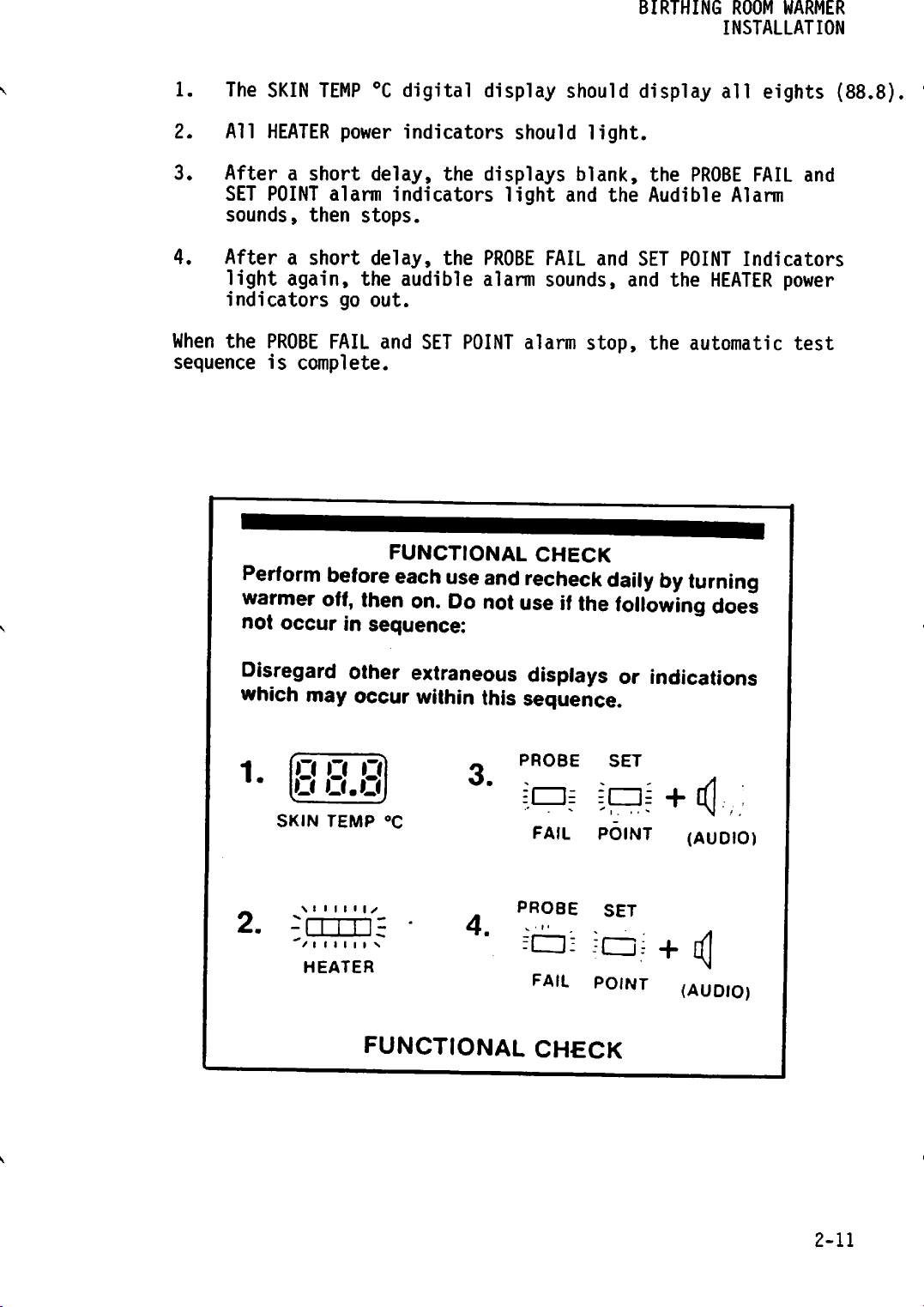
1.
The
SKIN
TEMP
°C
digital
display
should
BIRTHING
display
ROOM
INSTALLATION
all
WARMER
eights
(88.8).
2.
3.
4.
All
Afterashort
SET
sounds,
Afterashort
light
indicators
When
the
sequence
Perform
warmer
not
HEATER
POINT
then
again,
PROBE
is
complete.
occur
power
alarm
go
FAIL
before
indicators
delay,
indicators
stops.
delay,
the
audible
out.
and
SET
FUNCTIONAL
each
off, then on.
in
sequence:
the
displays
light
the
PROBE
alarm
POINT
use
and
Do
notuse ifthe
should
and
FAIL
sounds,
alarm
CHECK
recheck
light.
blank,
and
stop,
the
and
the
Audible
SET
POINT
the
the
automatic
dailybyturning
following
PROBE
Alarm
HEATER
does
FAIL
and
Indicators
power
test
Disregard
other extraneous displays or indications
which may occur within this sequence.
PROBE
fcU
FAIL
PROBE
=• =
FAIL
CHECK
S +4,:
POINT
-=c±i+i<|
P0INT
2.
o o o
U
SKIN
\ i i i i i i •
/I
HEATER
U.U
TEMP
I I I I I s
°C
FUNCTIONAL
3.
4.
SET
(AUDIO)
SET
(AUDIO)
2-11
BIRTHING
INSTALLATION
ROOM
WARMER
D.
E.
F.
G.
H.
I.
J.
DEPRESS
indicate
DISCONNECT
FAIL
Reconnect
SET THE
should flash on and off continuously.
SET
indicator;
SLIDE
HEATER Indicators should be illuminated when the control is set
to
SET THE EXAMINATION LIGHT SWITCH on the Warmer Module to the ON-1
position;
the
DEPRESS
delay,acontinuous
switch;
THE
36.0±0.1°C
Indicator
CONTROL
THE
HEAT
THE
MAX
position.
OFF-0
AND
the
CAL
CHECK
THE
POWER
should
the
power
MODE
CONTROL
all
indicator
HEAT
the
CONTROL
examination
position;
HOLD
THE
alarm
should
SWITCH;
to
CORD
light,
cord
SWITCH
TO
MIN
slowly
the
examination
SILENCE/RESET
audible
the
indicate
PLUG
and
plug,
TO
and
lamps
toward
lamp
alarm*
stop.
SKIN
that
from
the
the
the
alarm
MANUAL;
observe
should
should
light
SWITCH.
should
TEMP
the
wall
audible
should
the
the
be
off.
MAX
position;
light.
should
sound.
°C
display
unit
outlet,
alarm
MANUAL
HEATER
Set
After a
is
calibrated.
the
should
stop.
indicator
power
the
the
switch
go
out.
15-second
Release
should
POWER
sound.
four
to
the
I
K.
DEPRESS
occur:
1.
2.
THE
The
START/RESET
minute.
APGAR
TIMER
After1minute
TIMER
should
Indicator
has
light
START/RESET
elapsed,
and
"chirp."
3.
4.
L.
THE ELECTRICAL CHECKOUT IS COMPLETE.
Controller
off
The
numbers
in
sequence
annunciator
After
11
minutes
automatically
Model
chirping
alarm
"2"
through
at
1-minute
should
has
turn
CMB78-1
should
"chirp"
off.
SWITCH;
should
the
the
APGAR
"10"onthe
intervals
at
the
elapsed,
Series02- a
sound.
the
light
number
audible
APGAR
and
5-
and
APGAR
one
the
following
and
go
"1"
on
annunciator
TIMER
the
APGAR
10-minute
TIMER
second
on/one
out
after
the
APGAR
should
audible
counts.
should
should
1
should
light
second
2-12
BIRTHING
ROOM
WARMER
INSTALLATION
MECHANICAL
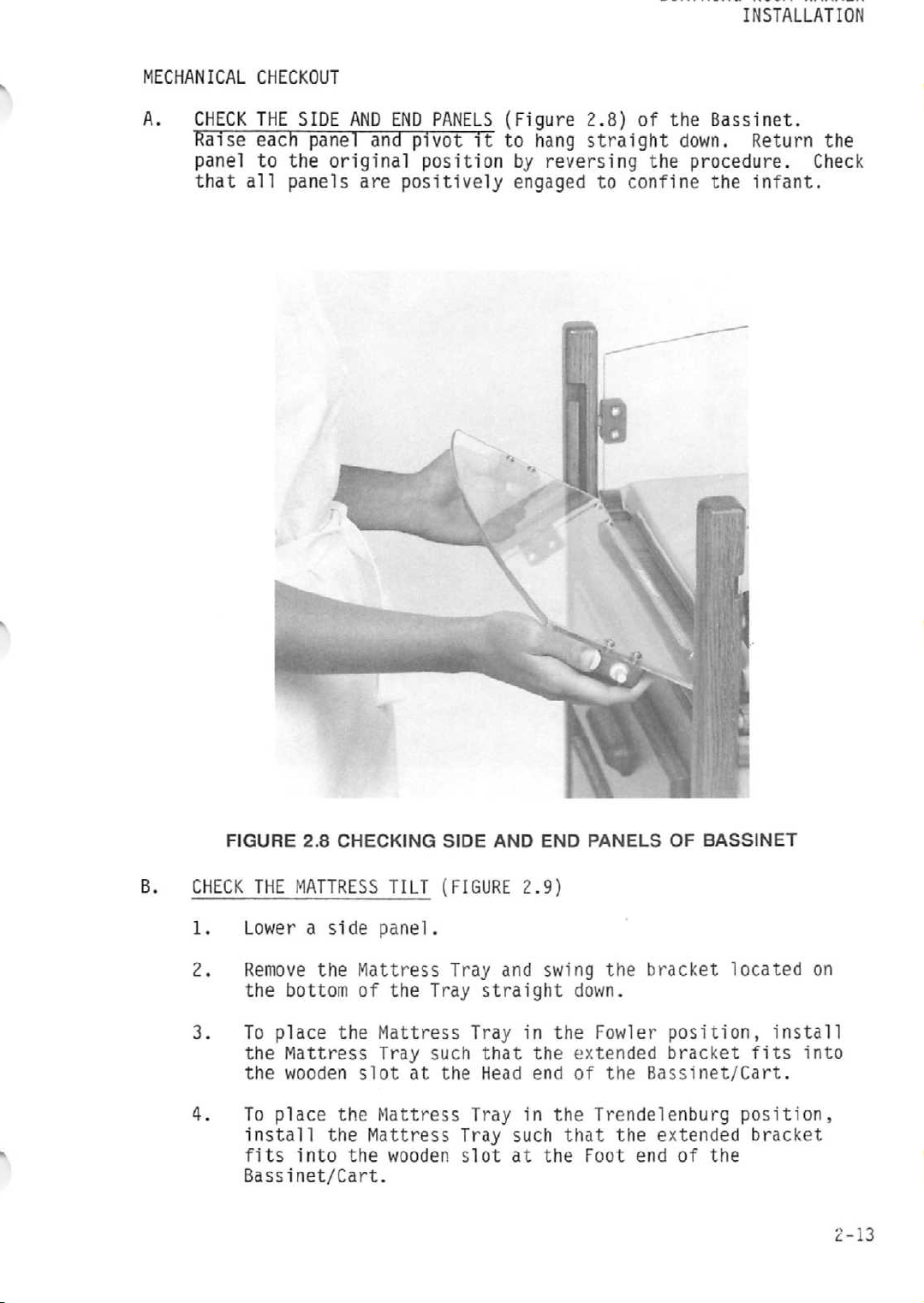
A.
CHECK
Raise
panel
that
CHECKOUT
THE
each
to
the
all
panels
SIDE
panel
original
AND
are
END
PANELS
and
pivot
position
positively
(Figure
it
to
hang
by
reversing
engaged
2.8)
of
straight
the
to
confine
the
Bassinet.
down.
procedure.
the
Return
infant.
the
Check
B.
FIGURE
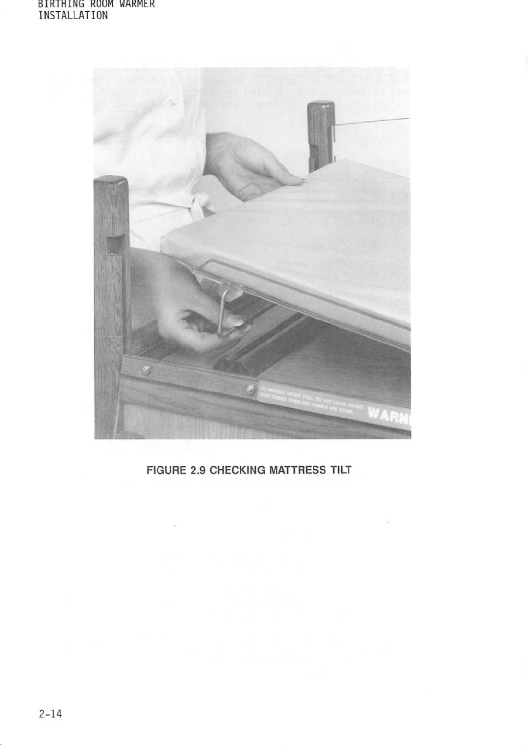
CHECK
1.
2.
3.
4.
2.8
CHECKING
THE
MATTRESS
Lower a
Remove
the
To
place
the
the wooden slot at the Head end of the Bassinet/Cart.
To
place
install
fits
Bassinet/Cart.
side
the
bottom
Mattress
the
into
TILT
panel.
Mattress
of the Tray
the
Mattress
Tray
the
Mattress
Mattress
the
wooden
SIDE
(FIGURE
Tray
Tray
such
Tray
Tray
slot
AND
END
2.9)
and
swing
straight
in
that
the
in
such
at
the
PANELS
the
down.
the
Fowler
extended
the
Trendelenburg
that
the
Foot
OF
bracket
position,
bracket
extended
end
of
BASSINET
located
install
fits
position,
bracket
the
on
into
2-13
BIRTHING
ROOM
INSTALLATION
WARMER
2-14
FIGURE
2.9
CHECKING
MATTRESS
TILT
 Loading...