

Air M5A Maintenance Instructions
TM
8-6520-003-24&P
UNIT,
COMPRESSOR-DEHYDRATOR,
DIRECT
MAINTENANCE
(INCLUDING
TECHNICAL
SUPPORT,
REPAIR
SPECIAL
AND
TOOLS
MANUAL
GENERAL
MANUAL
PARTS
LIST)
SUPPORT
AND
(SERIAL
APPROVED
HEADQUARTERS,
DENTAL,
NUMBERS
6520-00-139-1246
FOR
PUBLIC
MODEL
2700
RELEASE;
DEPARTMENT
DISTRIBUTION
M5B
AND
OF
ABOVE)
IS
UNLIMITED
THE
ARMY
1991
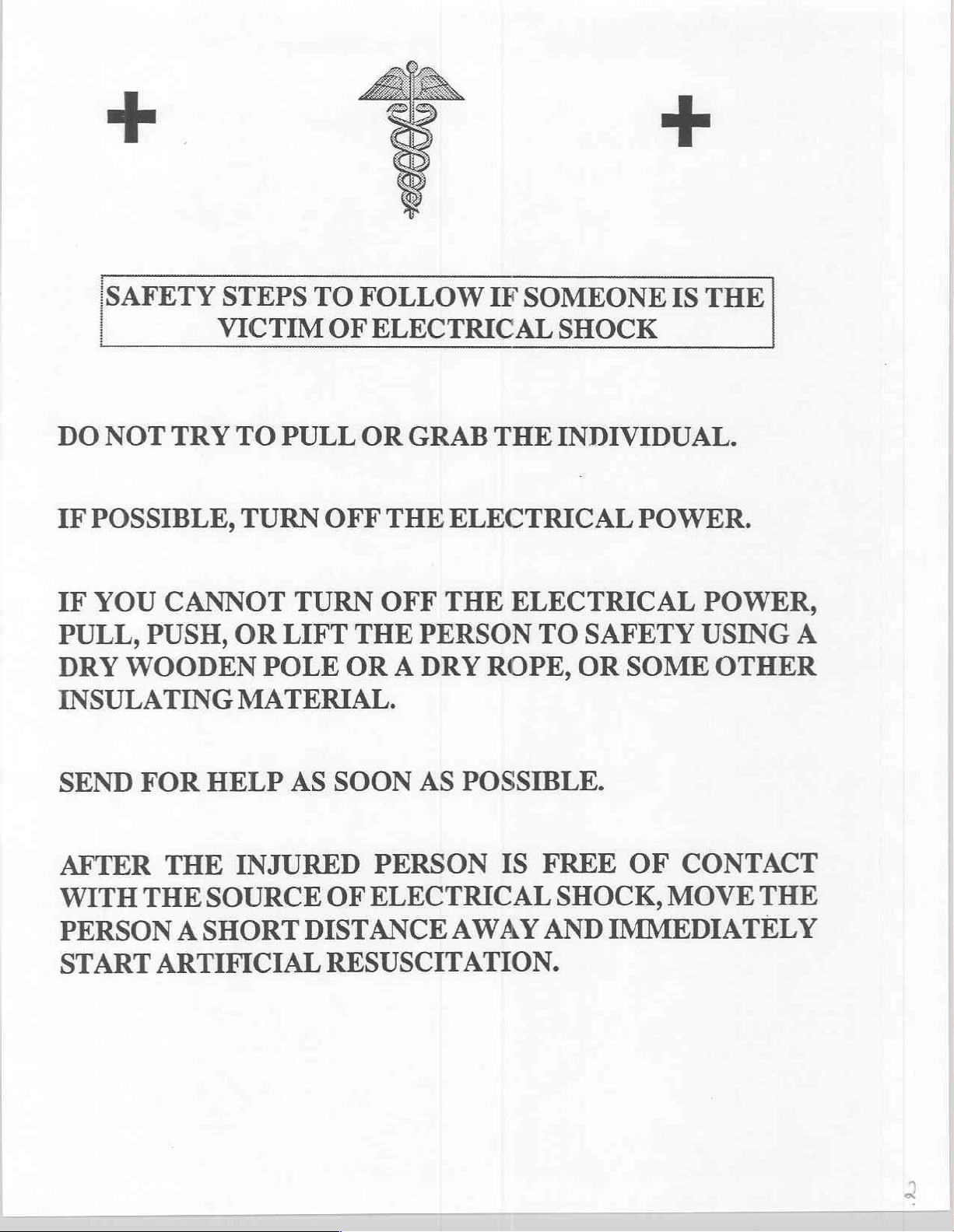
SAFETY
STEPS
TO
FOLLOW
IF
SOMEONE
IS
THE
|
DO
IF
IF
NOT
POSSIBLE,
YOU
PULL,
DRY
PUSH,
WOODEN
TRY
CANNOT
INSULATING
VICTIM
TO
PULL
TURN
TURN
OR
LIFT
POLE
MATERIAL.
OF
ELECTRICAL
OR
OFF
GRAB
THE
OFF
THE
OR
A
THE
ELECTRICAL
THE
ELECTRICAL
PERSON
DRY
ROPE,
SHOCK
INDIVIDUAL.
POWER.
TO
SAFETY
OR
SOME
POWER,
USING
OTHER
A
SEND
FOR
AFTER
WITH
THE
PERSONA
START
HELP
THE
INJURED
SOURCE
SHORT
ARTIFICIAL
AS
SOON
AS
PERSON
OF
ELECTRICAL
DISTANCE
RESUSCITATION.
POSSIBLE.
IS
FREE
SHOCK,
AWAY
AND
OF
CONTACT
MOVE
IMMEDIATELY
THE
TM
8-6520-003-24&P
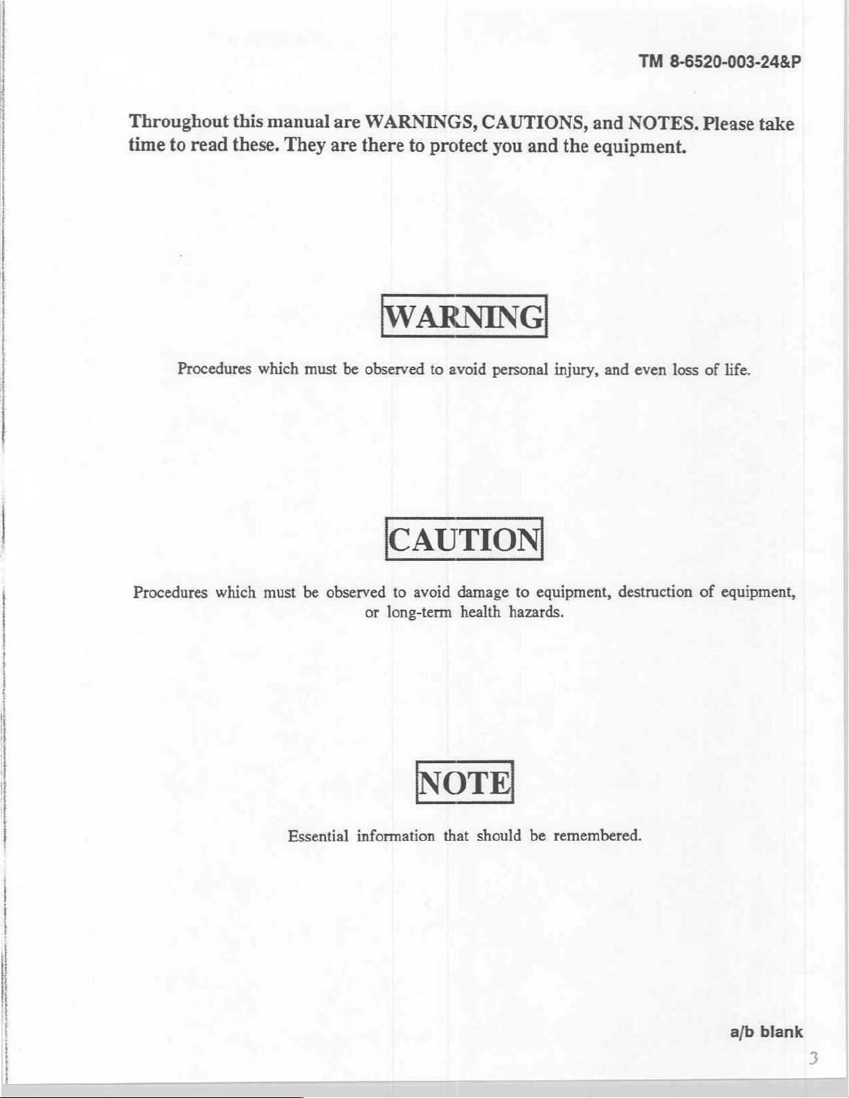
Throughout
to
time
read
Procedures
this
manual
these.
They
which
are
must
are
WARNINGS,
there
be
observed
CAUTIONS,
to
protect
WARNING
to
avoid
you
and
personal
and
the
equipment.
injury,
NOTES.
and
even
loss
Please
of
life.
take
|
Procedures
which
must
be
Essential
observed
or
information
CAUTION
to
avoid
long-term
damage
health
NOTE
that
should
to
equipment,
hazards.
be
remembered.
destruction
of
equipment,
|
a/b
blank
>
TM
8-6520-003-24&P
TECHNICAL
NO.
8-6520-003-24&P
MANUAL
(INCLUDING
You
can
prove
procedures,
mended
Changes
Commander,
5001. A reply
UNIT,
DIRECT
SUPPORT,
MAINTENANCE
REPAIR
PARTS
COMPRESSOR-DEHYDRATOR,
(SERIAL
NUMBERS
6520-00-139-1246
help
improve
Changes
to
Equipment
U.S.
will
this
please
to
Army
be
let
Publications
Technical
Medical
furnished
manual.
us
know.
Materiel
directly
If
you
Mail
and
Blank
Publications)
to
-
AND
AND
find
any
your
Forms),
Agency,
you.
GENERAL
MANUAL
SPECIAL
DENTAL,
2700
located
AND
mistakes
memorandum,
or
DA
in
ATTN:
WASHINGTON,
MODEL
ABOVE)
or
if
you
DA
Form
2028-2
the
back
SGMMA-M,
HEADQUARTERS
DEPARTMENT
DC
SUPPORT
TOOLS
know a way
Form
2028
(Recommended
of
this
manual,
Frederick,
OF
LIST)
M5B
to
im-
(Recom-
to:
MD
THI
siasi
21702-
CHAPTER
Section
CHAPTER
Section
Approved
HOW
TO
USE
1.
INTRODUCTION
I.
General
Il
Equipment
lll.
Principles
2.
OPERATINGINSTRUCTIONS
1
“Operating
II.
UnitOperation
Ill.
Operation
IV.
Operation
Information
for
public
release;
TABLE
TRISIMANHAE
Description
of
Operation .........
Controls
................
of
Auxiliary
Under
and
Equipment
Unusual
Data
is
Conditions
OF
oo
e
ss
distribution
is
unlimited.
CONTENTS
っ
μάς
.
>
seere
...
........................................
Ed
δώ
ναι.
eee
616/016 9 0804
cree
ala
ler
ao
ee
ο
Page
ele 5 iv
e
21
„21
>
2-3
-
TM
8-6520-003-24&P
CHAPTER
Section
CHAPTER
Section
APPENDIX
GLOSSARY
INDEX
3.
L
Il
ИИ.
м.
V.
Vi.
Vil.
Vill.
IX.
4.
1.
Il
A
B.
C.
D.
Е,
UNIT
LEVEL
General
Service
Lubrication
Preventive
Functional
Troubleshooting
Maintenance
Cleaning
Storage
DIRECT
General
Troubleshooting
REFERENCES
MAINTENANCE
COMPONENTS
EXPENDABLE
REPAIR
MAINTENANCE
Information
Upon
Receipt
Instructions
Maintenance
Testing
Instructions
Procedures
and
Shipment
SUPPORT
Information
AND
PARTS
of
Equipment
............
Checks
...
.....
.
Procedures
AND
GENERAL
..
ALLOCATION
OF
END
ITEM
DURABLE
AND SPECIAL
and
Services
.
SUPPORT
CHART
AND
BASIC ISSUE
SUPPLIES
TOOLS
LIST
MAINTENANCE
AND
MATERIALS
ITEMS
LIST
LIST
.
Figure
1-1
1-2
1-3
1-4
15
16
17
18
31
32
E-1
E-2
E-4
ES
ES
No.
Case
data
plate
Air
relief
valve
data
plate
Storage
Tank
Pressure
Unloader
Electrical
Motor-compressor
Motor-compressor
Electrical
Regeneration
Compressor-dehydrator . .
Drying
Electrical
Flow
Unloadervalve
Motor-compressor
tank decal
drain
decal
switch
valve
power
wiring
chamber
assemblies
control
valve
decal
instructional
cable
tag
pumping
purging
diagram
diagram
and
....
...
cooling
..
decal
....
cycle
cycle
26
coil
Title
.........................................
sees
assemblies
rei
iii
Page
Table
No.
LIST
OF
Title
TABLES
TM
8-6520-003-24&P
Page
11
12
13
21
31
32
Nomenclature
Specifications
Physical
Operating
PMCS
General
cross-reference
characteristics
load
troubleshooting
list
factors
....
TM
8-6520-003-24&P
Lİ
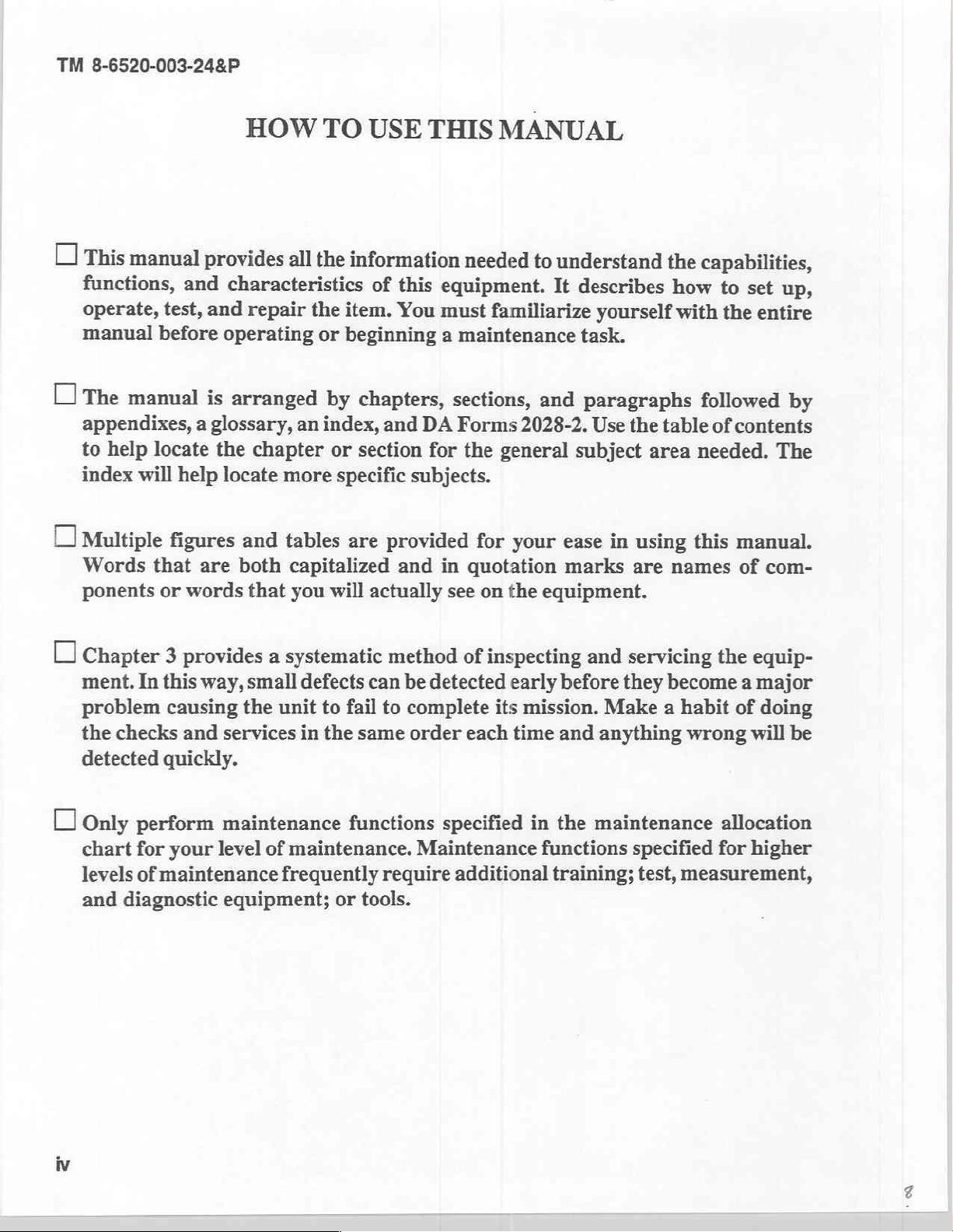
This
manual
functions,
operate,
manual
Lİ
The
manual
appendixes,
to
help
index
O
Multiple
Words
ponents
test,
before
locate
will
help
figures
gui
that
or
HOW
provides
and
characteristics
and
repair
operating
is
arranged
a
glossary,
the
chapter
locate
and
are
both
words
that
TO
USE
all
the
information
of
the
item.
or
beginning
by
chapters,
an
index,
or
more
tables
capitalized
you
will
and
section
specific
are
actually
THIS
this
equipment.
You
must
a
maintenance
sections,
DA
Forms
for
subjects.
provided
and
in
see
MANUAL
needed
the
for
quotation
on
to
familiarize
and
2028-2.
general
your
y
the
equipment.
understand
It
describes
yourself
task.
paragraphs
Use
the
subject
ease
in
using
marks
are
the
how
with
table
area
g
names
capabilities,
to
set
up,
the
entire
followed
of
contents
needed.
this
manual.
of
by
The
com-
O
Chapter 3 provides a systematic
ment.
problem
the
detected
O
Only
chart
levels
and
In this
checks
way,
causing
and
quickly.
perform
for
your
of
maintenance
diagnostic
small
the
services
maintenance
level
equipment;
defects can
unit
in
of
maintenance.
frequently
to
the
method
be
fail to
same
functions
or
complete
order
require
tools.
of
inspecting
detected
specified
Maintenance
additional
its
each
early
mission.
time
and
before
Make a habit
and
anything
in
the
maintenance
functions
training;
servicing
they
become a major
wrong
specified
test,
measurement,
the
equip-
of
doing
will
be
allocation
for
higher
TM
8-6520-003-24&P
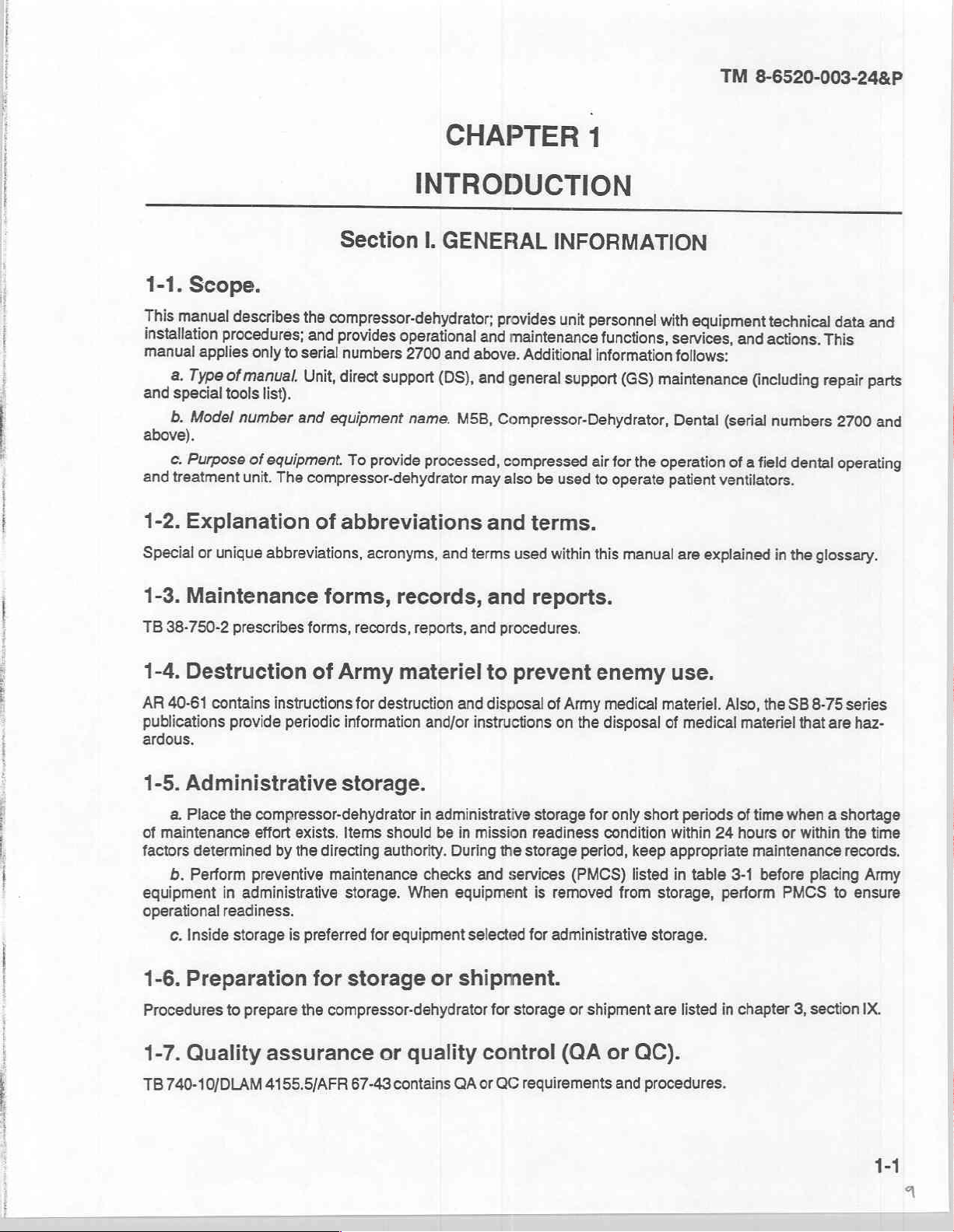
Scope.
1-1.
This
manual
installation
manual
and
above).
and
1-2.
Special
applies
a.
Type
special
b.
Model
c.
Purpose
treatment
Explanation
or
describes
procedures;
only
to
of
manual.
list).
tools
number
of
equipment.
unit.
The
unique
abbreviations,
CHAPTER
INTRODUCTION
Section
the
compressor-dehydrator;
and
provides
serial
numbers
Unit,
direct
and
equipment
To
provide
compressor-dehydrator
of
abbreviations
acronyms,
I.
GENERAL
operational
2700
and
support
(DS),
name.
processed,
and
INFORMATION
provides
and
maintenance
above.
and
general
M5B,
Compressor-Dehydrator,
compressed
may
also
and
terms
unit
Additional
support
be
used
terms.
used
within
air
1
personnel
functions,
information
for
to
operate
this
with
(GS)
maintenance
the
operation
manual
equipment
services,
follows:
Dental
patient
(serial
ventilators.
are
explained
of
technical
and
actions.
(including
numbers
a
field
dental
in
the
data
and
This
repair
parts
2700
and
operating
glossary.
1-3.
Maintenance
TB
38-750-2
1-4.
Destruction
AR
40-61
publications
ardous.
1-5.
Administrative
a.
of
maintenance
factors
b.
equipment
operational
c.
1-6.
Procedures
prescribes
contains
provide
Place
the
determined
Perform
in
administrative
readiness.
Inside
storage
Preparation
to
prepare
forms,
forms,
of
Army
instructions
periodic
information
records,
records,
materiel
for
destruction
storage.
compressor-dehydrator
effort
exists.
by
the
preventive
is
Items
should
directing
maintenance
preferred
for
the
compressor-dehydrator
authority.
storage.
When
for
equipment
storage
and
reports,
and
to
and
disposal
and/or
in
checks
instructions
administrative
be
in
mission
During
and
equipment
selected
or
shipment.
for
reports.
procedures.
prevent
of
Army
on
storage
readiness
the
storage
services
is
removed
for
administrative
storage
or
enemy
medical
the
disposal
for
only
condition
period,
(PMCS)
shipment
short
keep
listed
from
use.
materiel.
of
medical
periods
within
appropriate
in
table
storage,
storage.
are
listed
Also,
materiel
of
time
24
hours
maintenance
3-1
perform
in
chapter
the
SB
8-75
series
that
are
when a shortage
or
within
the
records,
before
PMCS
3,
placing
to
section
haz-
time
Army
ensure
IX.
1-7.
Quality
TB
740-10/DLAM
assurance
4155.5/AFR
67-43
or
quality
contains
control
QA
or
QC
requirements
(QA
or
QC).
and
procedures.
1-1
TM
8-6520-003-24&P
1-8.
Nomenclature
Table
1-1
identifies
Case
1-9.
Reporting
improvement
AR
40-61
prescribes
reports
for
the
compressor-dehydrator.
cross-reference
official
Common
Compressor-dehydrator
Drying
Fan Dryer
Female
Male
Power
versus
name
chamber
quick-disconnect
commonly
Table
quick-disconnect
switch
and
processing
used
1-1.
Nomenclature
list.
nomenclatures.
cross-reference
medical
Official
Storage
Compressor-dehydrator,
Dehydrator
cooling
Coupling,
Coupling,
*ON'POFF"
materiel
reports.
procedures
for
submitting
medical
materiel
complaints
list.
nomenclature
and
shipping
case
dental
fan
half,
quick-disconnect,
half,
quick-disconnect,
circuit
breaker
complaints
and/or
quality
female
male
and/or
improvement
quality
1-10.
A
1-11.
compressed
protective
air
1-12.
An
as
circuit
switch
to
processed
Warranty
warranty
is
Equipment
a.
The
compressor-dehydrator
b.
The
unit
c.
The
compressor-dehydrator
cover
d.
The
compressor-dehydrator,
to
multiple
Description
a.
Motor-compressor.
intake
silencer
b.
Fan.
The
the
power
с.
Unloader
for
air
d.
Pressure
opens
e.
Storage
operate
f.
Humidity
g.
Pressure
attached
air.
information.
not
applicable.
Section
air
free
of
oil,
contains
during
patient
switch
to
and
ventilators.
is
mounted
fan
provides a steady
is in
valve.
The
flow
from
switch.
closes
tank.
The
equipment. A drain
indicator.
gauge.
Il.
EQUIPMENT
characteristics,
is a compact,
moisture,
an integral
operation.
of
The
the
"ON"
unloader
the
drying
The
pressure
the
unloader
storage
This indicator
This
gauge
and
particulate
moisture
includes a case
when
drying
used
significant
motor-compressor
on the
motor-compressor.
flow
of
position.
valve
is
chamber
switch
valve
and
tank
holds
the
valve
varies
displays
air
to
the
DESCRIPTION
capabilities,
portable,
matter.
assembly
and
its
lid
with a manifold
components.
produces
through
used
to
the
atmosphere.
is
mechanically
opens
processed,
is
located
from
pink
pressure
compressed
the
cooling
vent
the
and
closes
compressed
on
the
to
blue
of
the
and
and
self-contained
which
automatically
is
designed
assembly,
coil.
pressure
operated
bottom
processed
by
the
electrical
air
of
which
AND
features.
unit
to
serve
will
provide
air
that
requires
The
fan
operates
from
the
pressure
circuit
and
provides
the
tank
to
denotes
the
air.
DATA
that
provides
regenerates
as a sound
processed,
additional
continuously
compressor
in
the
air
storage
for
the
motor-compressor.
relatively
drain
the
air
amount
of
processed,
the
drying
suppressor
compressed
processing.
as
and
to
provide
tank.
stable
pressure
or
water.
moisture
agent.
and
long
a
The
in
the
1-2
h.
Safety
valve.
This
i.
Drying
chamber.
air.
j.
Flow
the
storage
the
atmosphere
k.
Case.
container.
control
The
tank
The
lid
valve.
during
during
case
of
operation.
1
Power
switch.
motor-compressor.
The
the
is
the
The
valve
the
used
case
vents
drying
chamber
The
flow
pumping
purging
to
store
is
designed
electrical
excessive
control
cycle
air
is
used
valve
and
provides
pressure
to
controls
cycle.
the
compressor-dehydrator
to
serve
as
power
switch
if
the
hold
desiccant
the
flow
a
metering
a
sound
includes
primary
that
of
compressed
orifice
when
suppressor
a
circuit
pressure
removes
to
expand
itis
notin
and
breaker
TM
switch
fails
moisture
air
from
the
processed
use
and
protective
as
a
protective
8-6520-003-24&P
to
from
drying
to
serve
cover
operate
the
air
properly.
compressed
chamber
as
it
flows
as
a
shipping
during
device
normal
for
to
to
the
1-13.
The
Tabulated
tabulated
data
sor-dehydrator.
a.
Specifications
physical
characteristics.
Electrical
Dimensions
Hoses
data.
provides
and
power
Voltage...
Frequency.
Current
Ambient
Normal
Maximum
(interconnecting
the
physical
...
temperature
operating
operating
specifications,
physical
characteristics.
Table
range
Table
1-3.
load
loa:
to
equipment
characteristics,
Tables
1-2.
Physical
1-2
Specifications.
characteristics.
and
1-3
provide
and
other
information
a
broad
range
for
the
compres-
of
specifications
and
b.
Identification,
(1)
(2)
to
the
cylindrical
is
shown
is
shown
in
in
instruction,
Case.
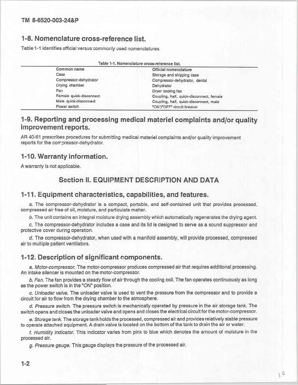
(a)
Identification
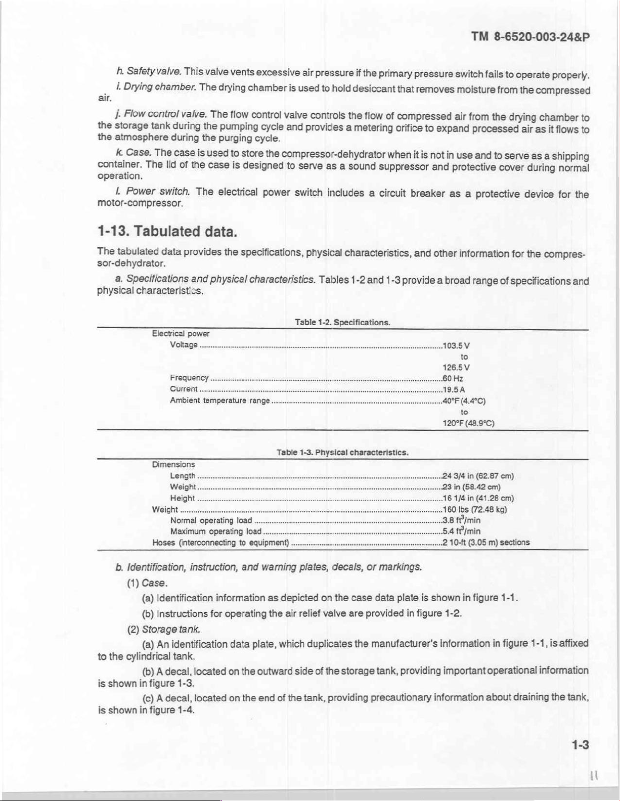
(b)
Instructions
Storage
(a)
tank.
An
identification
tank.
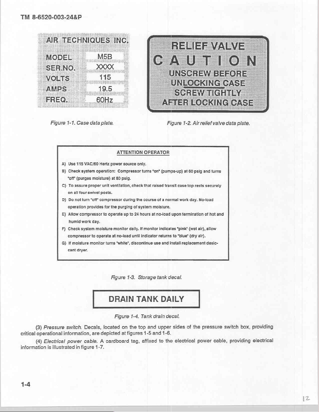
(b) A decal,
figure
located
1-3.
(0) A decal,
figure
1-4.
information
for
operating
located
and
data
plate,
on
the
on the
warning
as
depicted
the
air
which
outward
end
of
the
plates,
on
relief
valve
duplicates
side
of
the
tank,
providing
decals,
the
case
are
the
storage
or
markings.
data
plate
is
provided
in
figure
manufacturer's
tank,
providing
precautionary
shown
in
figure
1-2.
information
important
information
1-1.
in
figure
1-1,
operational
about
draining
is
affixed
information
the
tank,
1-3
TM
8-6520-003-24&P
Figure
1-1.
A)
Use
B)
Check
‘off
C)
To
on
D)
Do
operation
E)
Allow
humid
F)
Check
compressor
G)
Hf
cant
Case
data
115
VAC/60
Hertz
system
operation:
(purges
assure proper
all
not
moisture
moisture)
four
swivel
turn
"off'
compressor
provides
compressor
work
day.
system
moisture
to
operate
monitor
dryer.
plate.
ATTENTION
power
source
Compressor
at
80
psig.
unit
ventilation,
posts.
during
for
the
purging
to
operate
monitor
at
no-load
turns
“white”,
OPERATOR
only.
turns
check
that
the
course
of
system
up
to
24
hours
daily.
If
monitor
until
indicator returns
discontinue
Figure
"on"
(pumps-up)
raised
transit
of a normal
moisture.
at
no-load
indicates
use and
install
1-2.
at
60
case
top rests
work
day.
upon
termination
"pink"
(wet
to
"blue"
(dry
replacement
Air
relief
psig
and
securely
No-load
of
air),
air).
valve
turns
hot
and
allow
desic-
data
plate.
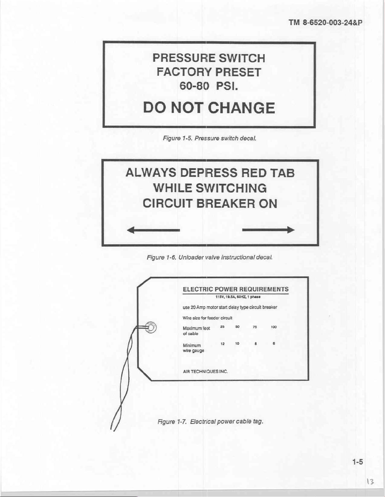
(3)
Pressure
critical
operational
(4)
Electrical
information
is
switch.
information,
power
illustrated
in
Figure
|
Decals,
are
cable. A cardboard
figure
DRAIN
located
depicted
1-7.
Figure
at
1-3.
Storage
TANK
1-4.
Tank
on the top
figures
tag,
1-5
affixed
drain
and
and
tank
decal.
DAILY
decal.
upper
sides
1-6.
to
the
of
the
electrical
power
pressure
cable,
switch
providing
box,
providing
electrical
TM
8-6520-003-24&P
PRESSURE
FACTORY
DO
ALWAYS
WHILE
CIRCUIT
—
60-80
NOT
Figure
1-5.
DEPRESS
SWITCH
PRESET
PSI.
CHANGE
Pressure
SWITCHING
BREAKER
switch
decal.
RED TAB
ON
Figure
A
ミノ
ミ
1-6.
Figure
Unloader
ELECTRIC
use
Wire
Maximumfet
of
Mina
wire
AIR
1-7.
valve
20
Amp
size
for
feeder
cable
gauge
TECHNIQUES
Electrical
instructional
POWER
motor
start
delay
circult
7%
2
INC.
power
decal.
REQUIREMENTS
type
circuit
breaker
©
ze
vw
cable
8
tag.
o,
1-5
TM
8-6520-003-24&P
1-14.
Model
differences
However,
such
engineering
1-15.
8.
Observe
pressure
b.
Ensure
c.
Refer
1-16.
The
operation
pumping
tion
of
the
tinue
to
fan
runs
1-17.
Model
design
Safety,
compressed
differences.
are
not
changes
changes
care,
each
WARNING,
air
that the
to
paragraph
compressor-dehydrator
applicable
in
assemblies,
will
be
and
be
may
3-22
for
Section
General.
of
the
compressor-dehydrator
cycle,
intake
air
is
compressed,
processed
automatically
continuously
Motor-compressor
air
in
occur
and
the
storage
during
the
processed
since
this
subassemblies,
published
in
handling.
CAUTION,
hazardous
guidance
the
on
III.
PRINCIPLES
cooled,
tank
is
operation
air
in
pumping
manual
supply
and
NOTE
personnel.
to
is
turned
cleaning
consists
dried,
vented
of
the
the
storage
cycle
covers
bulletins
of a pumping
back
a
single
model
or
components
and
in
this
manual.
off
when
it
the
intake
silencer
OF
and stored
through
compressor-dehydrator.
tank
is
supplied
(fig
1-8).
occur
subsequent
The
is
not
used
element.
OPERATION
cycle
and a purging
in
the
tank.
the
drying
as
and
serial
number
periodically.
changes
use
for
over
During a purging
chamber.
Throughout
needed.
to
of
electrical
24
hours.
cycle.
These
this
grouping.
Information
manual.
power
During
two
both
and
the
cycle, a por-
cycles
cycles,
on
high
con-
the
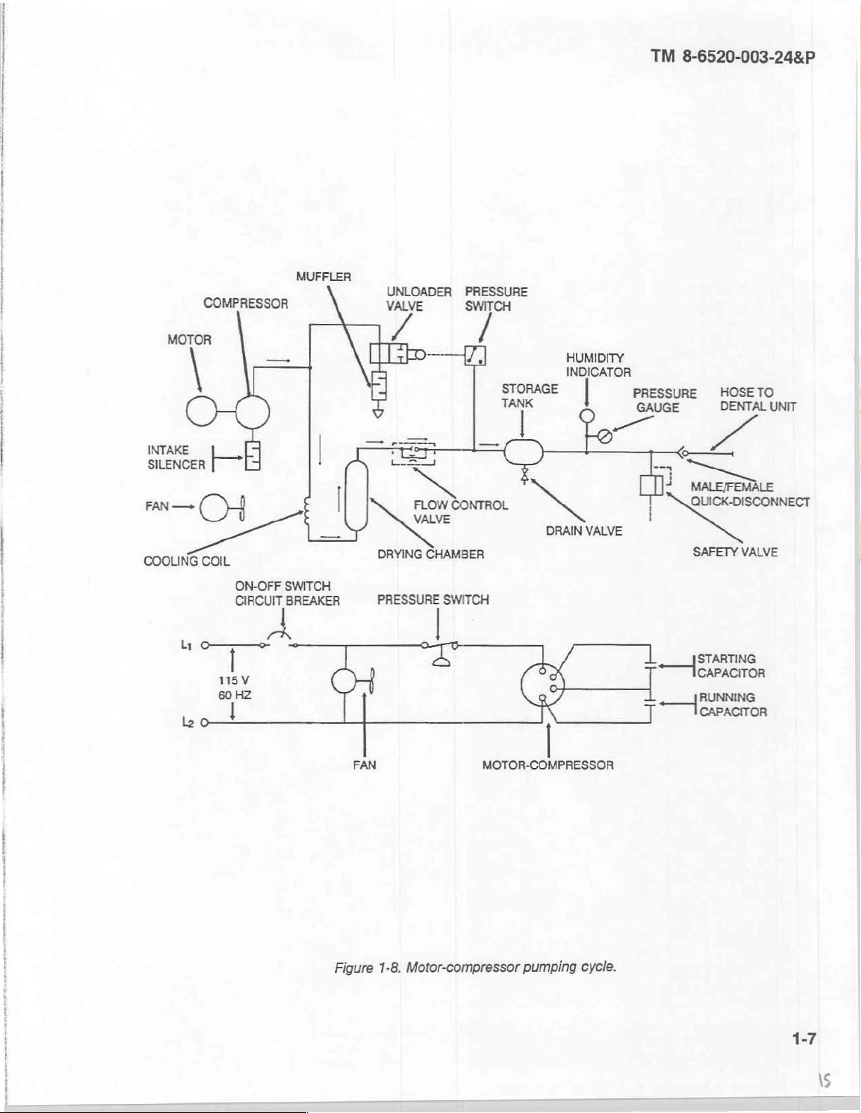
Initially,
closed.
from
into
The
tank.
the
sure
opened
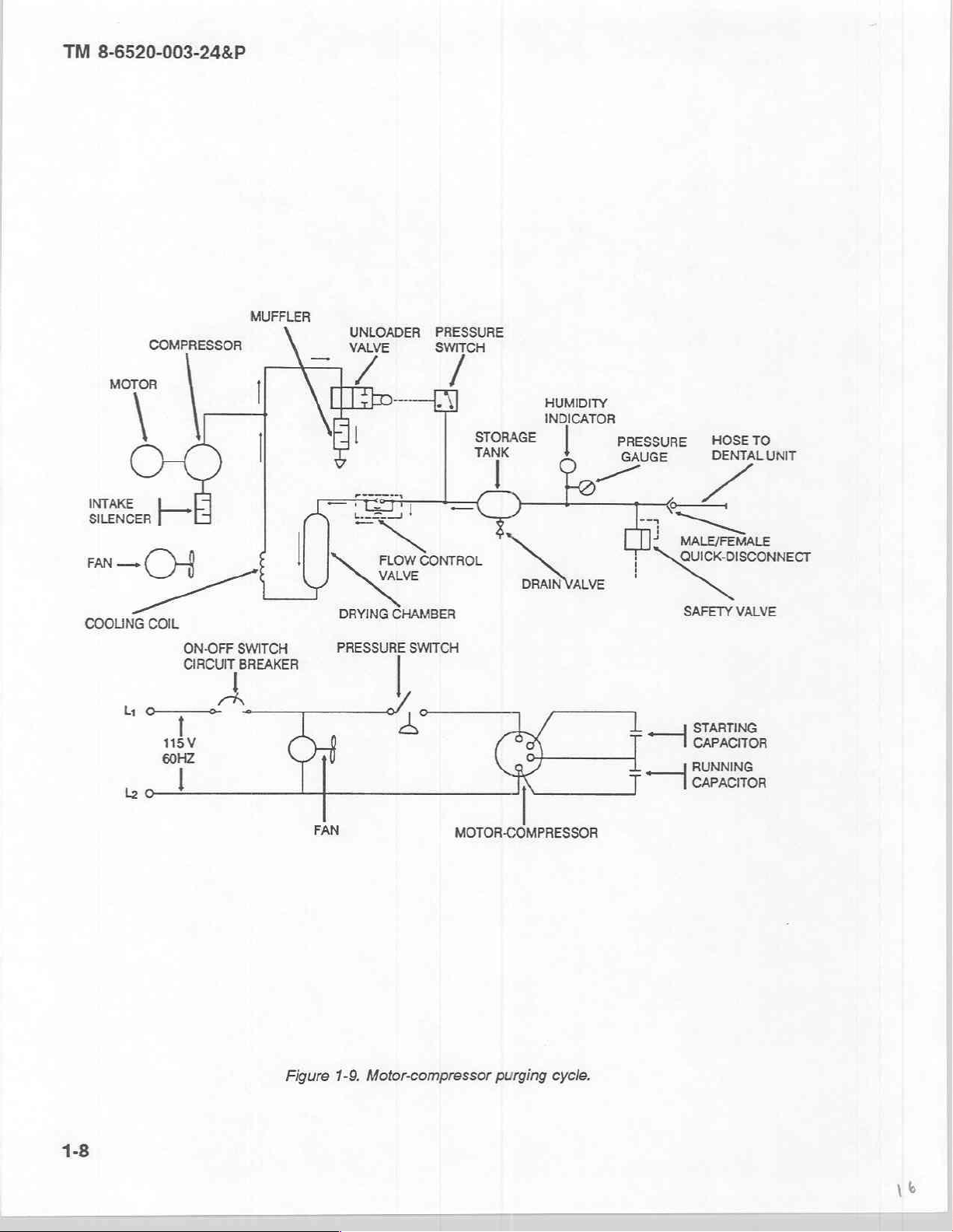
1-18.
The
chamber
orifice
passes
the
the
with
When
the
motor-compressor
the
storage
flow
control
The
gauge
amount
reaches
to
vent
Motor-compressor
purging
vented
in
the
through
atmosphere.
pumping
no
pressure
the
tank.
The
drying
valve
on the
of
moisture
80
psi,
the
cycle
to
flow
control
the
When
cycle
in
the
power
switch
is
chamber
contains a check
storage
in
the
the
pressure
compressor
begins
automatically
the
atmosphere,
valve
drying
the
begins
again.
chamber
air
storage
is
directed
tank
stored
and
tank,
the
turned
contains a desiccant
switch
on,
both
through
valve
indicates
air
by
its
opens
drying
chamber
to
the
color (blue
purging
when
the
and
the
processed
where
it
expands
and
absorbs
pressure
in
the
storage
unloader
the
the
allow
air
and
cycle
pumping
at a controlled
moisture
valve
motor-compressor
cooling
NOTE
stops
coil,
to
remove
the
processed,
pressure
for
dry
the
to
the
atmosphere.
motor-compressor.
(fig
cycle
air
in
the
from
tank
decreases
and
the
the
drying
moisture
within
and
1-9).
ends
storage
rate.
This
the
desiccant.
pressure
and
the
chamber,
from
compressed
the
tank.
The
pink
for
wet).
This
ends
with
the
unloader
tank
passing through a metering
large
This
to
60
psi,
switch
fan
start.
flow
the
compressed
air
to
humidity
When
The
the
volume
moisture
the
pressure
electrical
Compressed
control
enter
the
indicator
the
storage
unloader
pumping
valve
open,
of
dry,
expanded
is
switch
contacts
valve,
air.
storage
valve
cycle.
then
vented
closes
are
air
and
displays
tank
pres-
is
also
the
drying
air
to
and
1-6
M
COMPRESSOR
MOTOR
ーー
MUFFLER
[
UNLOADER
VALVE
ПЕР
PRESSURE
SWITCH
STORAGE
了
HUMIDITY
INDICATOR
PRESSURE
和
GAUGE
TM
8-6520-003-24&P
HOSE
DENTAL
TO
UNIT
—
<
т
QUIGK
DISCONNECT
INTAKE
SILENCER
CH
FAN
|
|
—
e
=
SS
—
CONTROL
FLOW
İM
5
Ke
VALVE
—
COOLING
CoIL
lei
ON-OFF
CIRCUIT
Î
SWITCH
BREAKER
n
DRYING
PRESSURE
CHAMBER
SWITCH
“a
1tsv
HZ
60
wo!
i
|
i
|
FAN
MOTOR-COMPRESSOR
N
VALVE
SAFETY
VALVE
L__yjsrarming
CAPACITOR
RUNNING
一
村
capacron
Figure
1-8.
Motor-compressor
pumping
cycle.
1-7
TM
8-6520-003-24&P
COMPRESSOR
MUFFLER
\
UNLOADER
VALVE
PRESSURE
SWITCH
mre
INTAKE
SILENCER
CH
—
FAN
μα.
En
y
o
115V
ve
ON-OFF
CIRCUIT
—
|
|
|
\
SWITCH
BREAKER
В
|
DRYING
PRESSURE
FAN
<
CONTROL
e
ANE
CHAMBER
SWITCH
ola
a
INDICATOR:
STORAGE
TANK
A
©
MOTOR-COMPRESSOR
Te
DRAIN
VALVE
PRESSURE
GAUGE
=
e
1
J
HOSETO
DENTAL
>
MALE/FEMALE
UNIT
QUICK-DISCONNECT
SAFETY
VALVE
STARTING
CAPACITOR
RUNNING
CAPACITOR
Figure
1-9.
Motor-compressor
purging
cycle.
TM
8-6520-003-24&P
2-1.
Controls
a.
Operating
Paragraph
b.
for a description
(‘ON"/"OFF")
2-2.
The
the
interconnecting
1-12
Operating
Initial
initial
start-up
a.
Remove
b.
Ensure
for a description
indicators include
and
start-up
the
that
OPERATING
Section
and
indicators.
controls consist
of
of
these
indicators.
the
hissing
procedures
lid
of
equipment
hose
sound
procedures.
for
the
case
and
supplied
is
temporarily
CHAPTER
I.
OPERATING
of
the
power
these
controls.
the
pressure
Additional
of
air
venting
Section
each
day
of
setitaside.
with
processed
disconnected
2
INSTRUCTIONS
CONTROLS
switch,
gauge
Il.
compressor-dehydrator
the
and
operating
through
UNIT
the
OPERATION
air
from
from
unloader
the
humidity
indicators
muffler
the
compressor-dehydrator
the
storage
valve,
during a motor-compressor
and
indicator.
include
operation
tank.
the
the
drain
Refer
position
are
as
valve.
back
to
of
the
follows:
is
either
Refer
back
paragraph
power
purging
switch
cycle.
turned
to
1-12
off
or
Do
not
c.
Ensure
d.
Check
e.
Set
motor-compressor
£
Observe
operate.
g.
Listen
again
start
Check
h.
procedures.
Connect
i.
Replace
j.
that the
and/or
the
power
the
for a hissing
operation
Pumping
the
that
not
Do
will
damage
the
the
use any
pressure
close
the
switch
and
the
pressure
sound
at
60
psi.
and
purging
humidity
the
use
the
hose(s)
the
on
lid
air
from
the
storage
gauge
drain
"ON"
fan
will
gauge.
indicator
compressor-dehydrator
handpieces
disconnected
if
four
begin
as
air
cycles
case
is
indicating
valve.
while
to
The
is
automatically
is
of
supports
tank
simultaneously
operate.
motor-compressor
will
continue
the
If
blue.
the
dental
preceding
the
in
to
NOTE
during
the
initial
"0."
depressing
should
vented
NOTE
indicator
through
to
alternate.
is
shut
pink, refer
WARNING
shows
pink
when
operating
suppress
and
treatment
paragraph
noise
the
start-up
the red tab
the
in
2-2b.
of
procedures.
off
at
80
muffler.
to
the
the
The
paragraph
humidity
unit.
motor-compressor.
on
the
unloader
psi.
The
fan
will
motor-compressor
the
for
3-20
indicator.
This
valve.
continue
regeneration
The
to
should
=
TM
8-6520-003-24&P
Do
not
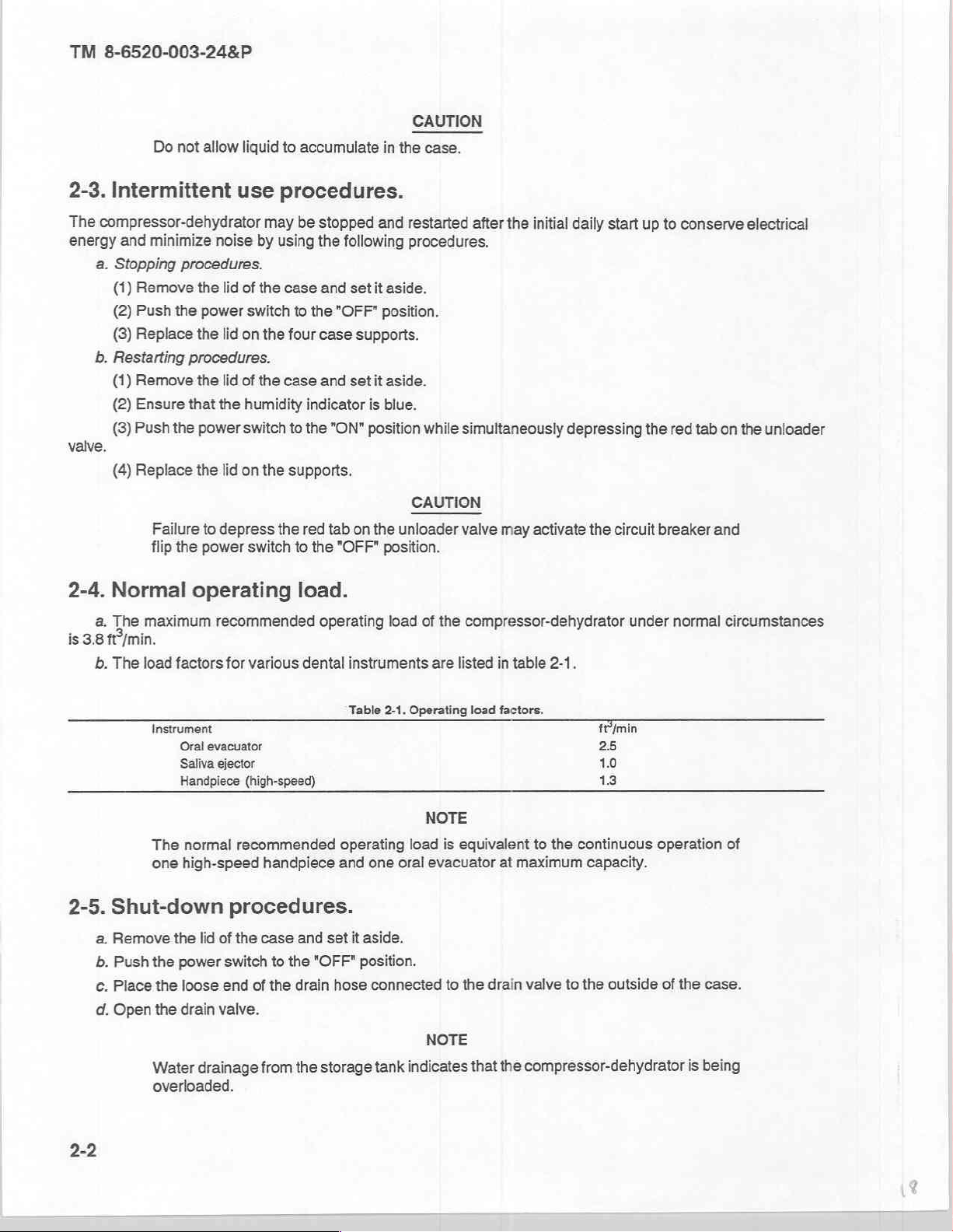
2-3.
Intermittent
The
compressor-dehydrator
energy
valve.
and
minimize
a.
Stopping
(1)
Remove
(2)
Push
(8)
Replace
b.
Restarting
(1)
Remove
(2)
Ensure
(3)
Push
(4)
Replace
flip
procedures.
the
procedures.
that the
the
Failure
the
allow
noise
the
lid
power
the
lid
the
lid
power
the
lid
to
depress
power
liquid
to
accumulate
use
procedures.
may
be
by
using
of
the
case
switch
to
on
the
four
of
the
case
humidity
switch
to
on the
supports.
the
red tab on the
switch
to
stopped
the
following
and
set
the
"OFF"
case
supports.
and
set
indicator
the
"ON"
position
the
"OFF"
CAUTION
in
the
and
restarted
procedures.
it
aside.
position.
it
aside.
is
blue.
CAUTION
unloader
position.
case.
after
while
simultaneously
valve
the
may
initial
daily
depressing
activate
the
start
up
the red
circuit
to
conserve
tab
breaker
electrical
on
the
and
unloader
2-4.
are
is
3.8
b.
2-5.
a.
b.
c.
d.
Normal
maximum
fť/min.
The
load
operating
factors
Instrument
Oral
Saliva
Handpiece
The
normal
one
high-speed
Shut-down
Remove
Push
Place
Open
the
lid
the
power
the
loose
the
drain
Water
drainage
overloaded.
recommended
for
various
evacuator
ejector
(high-speed)
recommended
handpiece
procedures.
of
the
case
switch
end
valve.
of
the
from
to
the
load.
operating
dental
operating
and
and
setit
"OFF"
drain
hose
the
storage
load
of
instruments
Table
2-1.
Operating
NOTE
load
one
oral
evacuator
aside.
position.
connected
NOTE
tank
indicates
the
compressor-dehydrator
are
listed
in
table
2-1.
load
factors.
is
equivalent
to
the
that
to
the
at
maximum
drain
valve
the
compressor-dehydrator
ft/min
25
1.0
13
continuous
capacity.
to
the
outside
under
operation
of
normal
the
case.
is
being
circumstances
of
2-2
e.
When
f.
Replace
the
pressure
the
lid
on
gauge
the
supports.
indicates
"0,"
close
the
drain
valve
and
place
the
TM
drain
8-6520-003-24&P
hose
back
inside
the
case.
Section
2-6.
Associated
No
associated
dehydrator,
2-7.
Associated
The
compressor-dehydrator
and
treatment
operation
support
Electrical
unit.
of
patient
Section
2-8.
High
Operation
moisture
the
desiccant
2-9.
Operation
a.
The
short-term
humidity
of
the
compressor-dehydrator
within
the
will
be
compressor-dehydrator
expedient
III.
OPERATION
support
items
of
power
supplied
items
equipment
by
material.
provides
The
compressor-dehydrator
ventilators.
IV.
OPERATION
processed,
conditions.
unit
that
cannot
accomplished
of
two
measure,
be
in
accordance
dental
has
of
are
supplied
generators
may
during
eliminated
periods
units.
the
capability
OF
AUXILIARY
equipment.
with
or
dedicated
is
required
compressed
also
UNDER
of
by
the
normal
with the
to
for
air
used
to
UNUSUAL
high
humidity
pumping
procedures
provide
EQUIPMENT
solely
numerous
for
the
operation
provide
sufficient
processed,
may
and
in
paragraph
air
for
items
support
of
of a field
of
equipment.
dental
compressed
CONDITIONS
result
in
the
accumulation
purging
to
cycles.
3-20.
support
two dental
the
compressor-
operating
air
for
the
of
Regeneration
units
as
of
a
The
is
one
b.
If
the
operation
instructions
to
the
to
handpieces
Operation
accumulate
to
maximum
eguivalent
oral
evacuator
in
adjust
the
dental
to
ensure
of
in
para
3-20
of
permissible
to
the
continuous
and
an
expedient
unit
their
two
dental
the
compressor-dehydrator
this
manual).
operating
the
intermittent
situation
control
peak
efficiency
units
operation
block.
in
an
CAUTION
load
to
support
of
two
operation
is
required,
This
adjustment
when
two
CAUTION
expedient
and
two
saliva
ejectors
of
two
refer
to
will
dental
units
situation
may
may
require
dental
units
is
at
maximum
high-speed
TM
8-6520-002-24&P,
permit higher
are
cause
periodic
handpieces.
operating
increased
regeneration.
5.4
ftÓ/min
air
simultaneously.
which
capacity
paragraph
pressure
moisture
(Refer
or
to
to
be
1-17,
for
delivered
TM
8-6520-003-24&P
|
3-1.
Overview.
Maintenance
unit
level
medical
quired
chapter
3-2.
Common
111.
3-3.
Components
3-4.
for
the
provides
Tools
tools
Refer
to
Components
Expendabie
Expendable
functions,
eguipment
equipment
instructions
and
and
test
your
unit's
of
end
and
durable
UNIT
both
except
test
equipment
modified
of
item
and
supplies.
supplies
CHAPTER
LEVEL
Section
preventive
repairer
for
and
information
equipment.
table
end
basic issue
and
I.
and
personnel.
some
tasks
required
of
organization
item
items
materials
GENERAL
corrective,
for
MAINTENANCE
These
involving
to
aid
in
maintenance
and
and
basic issue
are
listed
required
3
INFORMATION
that
are
beyond
personnel
the
performing
equipment
in
for
will
motor-compressor,
the
of
the
appendix
maintenance
the
scope
perform
required
equipment
(MTOE)
items.
C,
sections
are
of
the
majority
storage
tasks.
are
listed
for
authorized
II
and
listed
in
the
user
of
tank,
in
appendix
items.
III.
appendix
are
assigned
maintenance
and
case.
This
B,
section
D,
section
to
re-
II.
|
ㅣ
3-5.
Repair
Repair
3-6.
Special
Special
3-7.
Unpacking
a.
Unpacking
(1)
(2)
(3)
(4)
(5)
by
opening
(6)
parts
tools
Remove
Place
Loosen
Release
Ensure
the
Ensure
parts.
required
for
unit
level
tools.
maintenance
required
Section
The
for
II.
and
installing
the
unit.
compressor-dehydrator
the
compressor-dehydrator
the
compressor-dehydrator
the
screw
in
the
latches
eight
the
pressure
the
that
drain
valve.
that
the
drain
maintenance
the
of
SERVICE
is
air
relief
remove
and
is
gauge
valve
is
closed.
are
listed
in
appendix
compressor-dehydrator
UPON
the
from
further
no
designed
valve
on
the
indicating
RECEIPT
compressor-dehydrator.
shipping
the
feet
20
than
NOTE
outside
use
for
the
lid
of
the
case.
the
of
lid
storage
the
If
"0."
E,
are
carton
from
patient
case.
Set
section
listed
EQUIPMENT
OF
and/or
equipment
the
treatment
aside.
it
pressurized,
is
tank
Il.
appendix
in
crate.
E,
are
you
areas.
release
section
using.
the
III.
pressure
3-1

TM
8-6520-003-24&P
(7)
Ensure
(8)
Check
b.
Installing
(1)
Connect
More
compressor-dehydrator.
Refer
dehydrator
(2)
Connect
(3)
Provide
(4)
Rotate
right
at
case
the
(5)
Place
that
the
power
switch
the
compressor-dehydrator
the
unit.
either
one
or
two
than
two
interconnecting
to
TM
8-6520-002-248P
dental
a
to
the
electrical
environmental
the
four
case
angles.
the
lid
on
lid
the
supports.
power
protection
supports
is in
the
"OFF"
for
any
interconnecting
hoses
for
additional
unit.
cable
to
a
115-volt,
for
the
mounted
position.
damage
hoses
CAUTION
(a
combined
NOTE
compressor-dehydrator.
on
from
storage
to
a
dental
length
information
60-Hz
source
the
motor-compressor
operating
of
20
on
connecting
of
or
shipment.
and
feet)
may
power.
so that
treatment
damage
the
compressor-
they
overlap
unit.
the
the
edges
of
3-8.
General.
No
lubrication
Section
3-9.
General.
a.
The
compressor-dehydrator
for
operation
damage
b.
are
things
observing
©.
area
on
Operation, A -
at
or
failure.
Preventive
you
for
The
following
(1)
Item
the
Equipment
(2)
Interval.
of
the
unit
IV.
all
times.
Table
maintenance
should
improper
is a list
No.
This
This
After
Operation,
Section
is
required.
Ill.
PREVENTIVE
must
Inspection
3-1
contains
do
any
operational
of
column
Inspection
column
will
is
not
limited
time
you see
indicators,
the
PMCS
shows
and
shows
and S -
PMCS
the
when
Semi-annually.
LUBRICATION
MAINTENANCE
be
inspected
allow
defects
to
be
performed
to
performing
they
need
and
maintaining
table
headings
sequence
Maintenance
each
in
Worksheet,
PMCS
INSTRUCTIONS
and
serviced
to
be
discovered
the
to
be
with a description
which
to
item
B, D,
and A should
NOTE
systematically
by
unit
checks
done,
the
proper
do
the
DA
is
to
be
CHECKS
and
corrected
level
maintenance
and
services
such
as
checking
quantities
of
the
PMCS,
Form
and
2404.
serviced; B -
be
performed
AND
to
listed
information
is
used
Before
SERVICES
ensure
before
of
that
they
personnel.
in
the
for
general
operating
to
identify
Operation, D -
with
daily
the
result
PMCS
supplies.
in
each
the
use
unit
is
ready
in
serious
table.
There
cleanliness,
column:
equipment
During
of
the
unit.
(3)
Item
checked
orunusable.
or
serviced.
(4)
Equipment
3-2
When
items
when
to
the
eguipment
that
will
the
eguipment
be
Inspected
is
not
must
be
kept
not
disrupt
Ready/Available
operation.
can
be
and
Procedure.
shut
in
continuous
Perform
down.
This
If:.
This
column
column
operation,
the
complete
identifies
lists
conditions
check
daily
the
that
and
service
checks
general
make
only
and
services
area
or
the
equipment
those
specific
part
unavailable
to
be
ITEM
νο
INTERVAL
|
el
pl
als
ITEM
AND
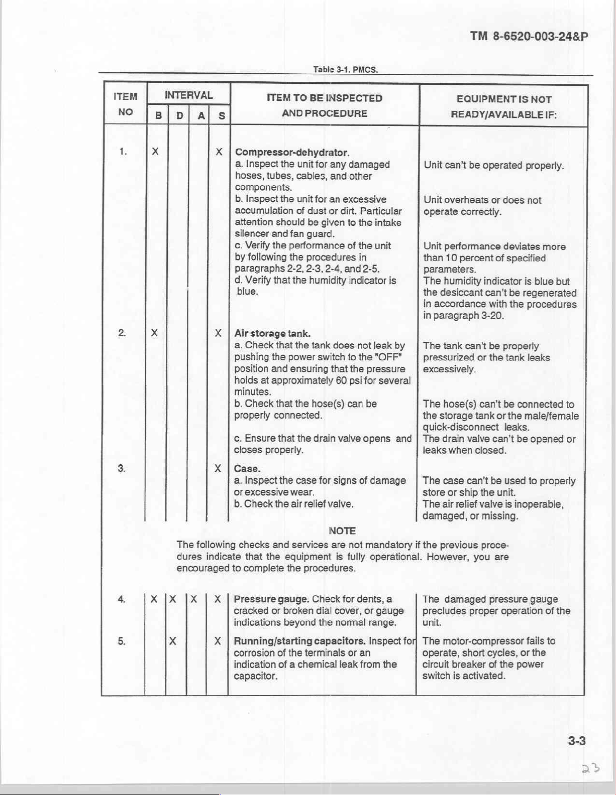
Table
3-1.
TO
BE
INSPECTED
PROCEDURE
PMCS.
TM
8-6520-003-24&P
EQUIPMENT
READY/AVAILABLE
IS
NOT
IF:
te
2:
x
X
X
|
Compressor-dehydrator.
a.
Inspect
hoses,
components.
b.
Inspect
accumulation
attention
silencer
c.
Verify
by
following
paragraphs
d.
Verify
blue,
X | Airstorage
a.
Check
pushing
position
holds
minutes.
b.
Check
properly
с.
Ensure
closes
the
unit
tubes,
cables,
the
unit
of
should
and
fan
the
performance
the
2-2, 2-3,
that
the
tank.
that
the
the
power
and
ensuring
at
approximately
that
the
connected.
that
the
properly.
for
any
damaged
and
other
for
an
excessive
dust
or
dirt.
be
given
to
guard.
of
procedures
2-4,
and
humidity
tank
switch
hose(s)
drain
indicator
does
to
that
the
60
psi
can
valve
Unit
can’t
Unit
overheats
Particular
the
intake
the
unit
in
2-5.
is
not
leakby | The
the
"OFF"
pressure | excessively.
for
several
be
opens
operate
Unit
performance
than
parameters.
The
humidity
the
desiccant
in
accordance
in
paragraph
tank
pressurized
The
hose(s)
the
storage
quick-disconnect
and | The
drain
leaks
10
percent
when
be
operated
or
does
correctly.
deviates
of
specified
indicator
can't
with
3-20.
can't be
valve
properly
or
the
can't
tank
or
can’t
closed.
tank
be
leaks.
properly.
not
more
is
blue
be
regenerated
the
procedures
leaks
connected
the
male/female
be
opened
but
to
or
3.
The
dures
encouraged
4.
5.
X
|X |X | X | Pressure
x X | Running/starting
X | Case.
a.
Inspect
or
excessive
b.
Check
following
checks
indicate
that
to
complete
cracked
indications
corrosion
indication
capacitor.
the
case
wear.
the
air
relief
and
services
the
equipment
the
procedures.
gauge.
or
broken
beyond
of
the
terminals
of a chemical
for
signs
of
valve.
NOTE
are
not
is
fully
Check
for
dents,
dial
cover,
the
normal
capacitors.
or
an
leak
from
damage | The
mandatory
operational.
or
gauge
range.
Inspect
the
if
a
for,
case
can't
store
or
ship
The
air
relief
valve
damaged,
the
However,
The
precludes
unit.
The
operate,
circuit
switch
or
previous
you
damaged
proper
motor-compressor
short
breaker
is
activated.
be
used
the
unit.
is
inoperable,
missing.
proce-
are
pressure
operation
cycles,
of
the
power
to
gauge
fails
or
the
properly
of
the
to
TM
8-6520-003-24&P
ITEM
NO
INTERVAL
Bl pl
als
ITEM
AND
Table
TO
BE
PROCEDURE
3-1.
PMCS - continued.
INSPECTED
EQUIPMENT
READY/AVAILABLE
IS
NOT
IF:
x
x X | Unloader
8.
3-10.
If
operator
must
unit
level
3-11.
хх
Reporting
personnel
report
them.
Refer
medical
General.
equipment
X | Safety
operation.
X | Humidity
a.
Inspect
indicator
indication.
b.
Ensure
deficiencies.
discover
to
TB
problems
38-750-2
repairer
Section
valve.
valve.
indicator.
for
dents, a cracked
cover,
that the
with
and
report
if
you
need
V.
Test
for
operation.
Check
or
the
for
proper
the
lack
of
indicator
equipment
the
assistance.
is
deficiency
FUNCTIONAL
or
broken | The
any
color | proper
blue.
during
PMCS
using
TESTING
The
valve
The
valve
humidity
The
humidity
than
blue.
that
they
the
proper
is
inoperable.
is
damaged
indicator
operation
indicator
are
unable
forms.
Consult
of
the
to
or
inoperable,
precludes
unit.
is
other
correct,
with
they
your
This
section
tial
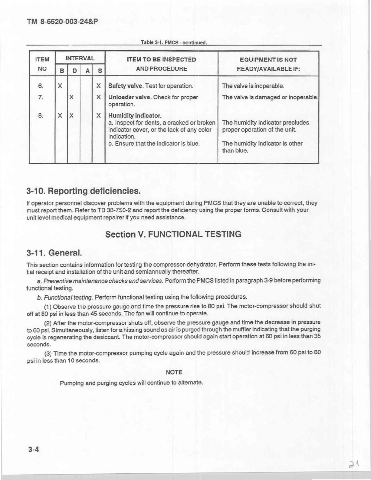
receipt
a.
Preventive
functional
off
at
60
to
cycle
seconds.
psi
testing.
b.
Functional
Observe
(1)
80
psi
After
(2)
Simultaneously,
psi.
regenerating
is
Time
(3)
in
less
than
contains
and
installation
maintenance
testing.
in
less
the
the
10
Pumping
information
of
Perform
pressure
the
than
45
motor-compressor
listen
desiccant.
the
motor-compressor
seconds.
and
for
the
unit
checks
functional
gauge
seconds.
for
purging
a
cycles
testing
and
The
hissing
The
the
compressor-dehydrator.
semiannually
and
services.
testing
the
time
and
fan
will
observe
off,
shuts
sound
motor-compressor
will
continue
cycle
pumping
thereafter.
Perform
using
pressure
continue
the
is
air
as
again
NOTE
to
alternate.
the
PMCS
the
following
rise
to
operate.
pressure
purged
should
the
and
Perform
listed
procedures.
psi.
80
to
gauge
through
start
again
pressure
these
in
paragraph
motor-compressor
The
time
and
muffler
the
operation
should
indicating
increase
tests
3-9
decrease
the
60
at
following
before
psi
that
in
from
performing
should
in
the
less
60
the
ini-
shut
pressure
purging
35
than
80
to
psi
3-4
TM
8-6520-003-24&P
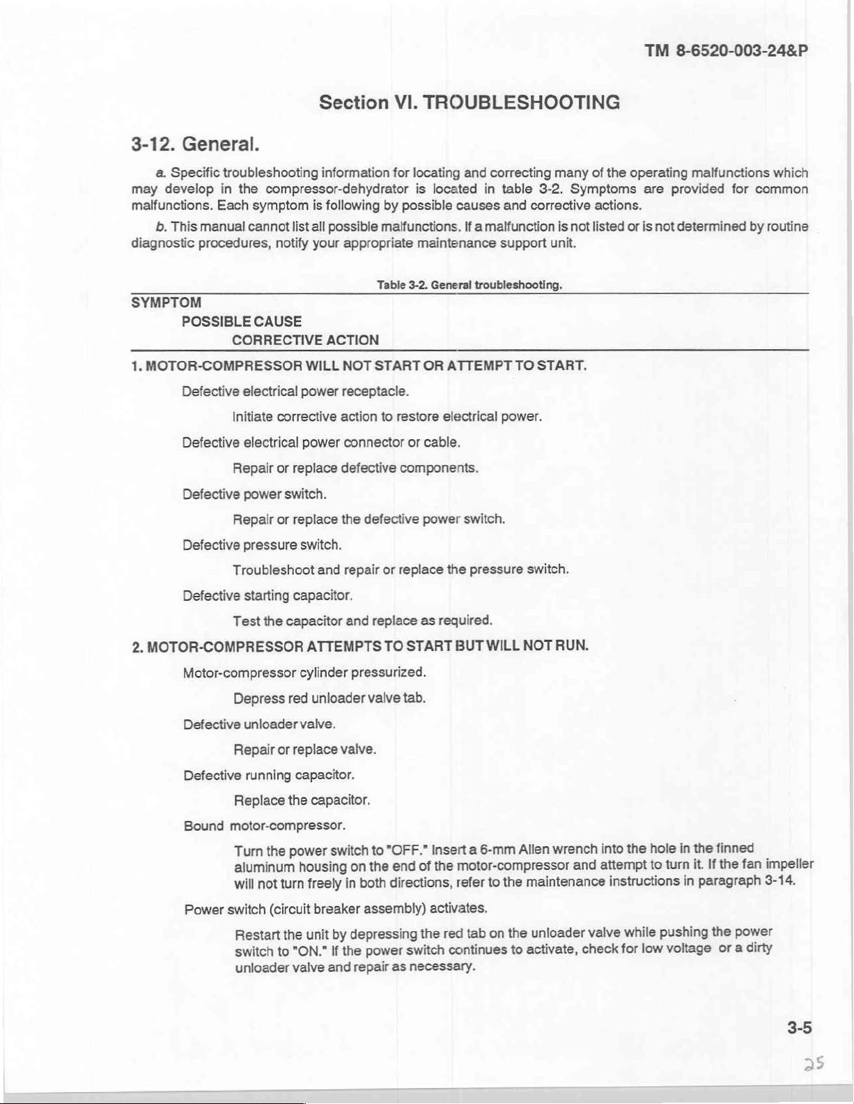
3-12.
may
malfunctions.
diagnostic
SYMPTOM
1.
General.
a.
Specific
develop
b.
This
MOTOR-COMPRESSOR
troubleshooting
in
Each
manual
procedures,
POSSIBLE
Defective
Defective
Defective
Section
information
the
compressor-dehydrator
symptom
cannot
CAUSE
CORRECTIVE
electrical
Initiate
electrical
Repair
power
is
following
list
all
possible
notify
your
ACTION
WILL
power
corrective
power
or
replace
switch.
action
defective
VI.
for
locating
by
possible
malfunctions.
appropriate
Table
3-2.
NOT
START
receptacle.
to
restore
connector
or
components.
TROUBLESHOOTING
and
is
located
maintenance
General
OR
electrical
cable.
in
causes
If a malfunction
troubleshooting.
ATTEMPT
correcting
table
and
support
power.
many
3-2.
corrective
unit.
TO
START.
of
Symptoms
actions.
is
not
listed
the
operating
or
are
is
not
provided
malfunctions
for
determined
which
common
by
routine
Defective
Defective
2.
MOTOR-COMPRESSOR
Motor-compressor
Defective
Defective
Bound
Power
Repair
Troubleshoot
Test
Depress
Repair
Replace
or
replace
pressure
starting
unloader
running
capacitor.
the
capacitor
red
or
replace
capacitor.
the
the
switch.
and
repair
and
ATTEMPTS
cylinder
unloader
valve.
valve.
capacitor.
pressurized.
motor-compressor.
switch
power
the
Turn
aluminum
not
will
switch
(circuit
Restart
switch
unloader
housing
turn
the
"ON."
to
valve
freely
unit
on
in
breaker
depressing
by
the
If
and
repair
defective
or
replace
replace
TO
START
valve
tab.
"OFF."
to
end
the
directions,
both
assembly)
switch
power
as
necessary.
power
switch.
the
pressure
as
required.
BUT
WILL
6-mm
a
Insert
motor-compressor
the
of
to
refer
activates.
tab on the
red
the
continues
switch.
NOT
Allen
maintenance
the
unioader
activate,
to
RUN.
wrench
and
valve
check
hole
the
into
turn
attempt
to
instructions
pushing
while
voltage
low
for
finned
the
in
If
it.
paragraph
in
the
the
power
a
or
impeller
fan
3-14.
dirty
3-5
D
un
TM
8-6520-003-24&P
SYMPTOM
POSSIBLE
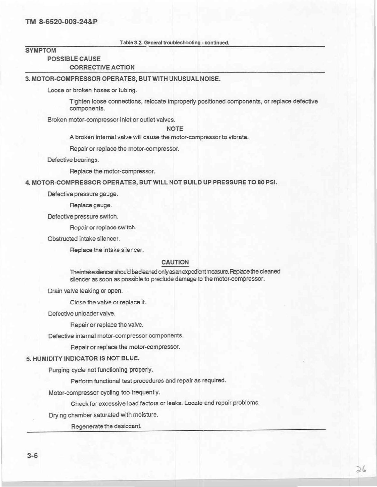
3.
MOTOR-COMPRESSOR
Loose
or
CAUSE
CORRECTIVE
broken
hoses
Table
ACTION
OPERATES,
or
tubing.
3-2.
BUT
General
WITH
troubleshooting - continued.
UNUSUAL
NOISE.
Broken
Defective
4.
MOTOR-COMPRESSOR
Defective
Defective
Obstructed
Tighten
loose
connections,
components.
motor-compressor
A
broken
Repair
bearings.
Replace
pressure
Replace
pressure
Repair
Replace
Theintakesilencer
silencer
internal
or
replace
the
gauge.
or
replace
intake
silencer.
the
as
motor-compressor.
OPERATES,
gauge.
switch.
intake
should
soon
as
relocate
inlet
or
outlet
valve
will
cause
the
motor-compressor.
BUT
WILL
switch.
silencer.
be
cleaned
possible
to
preclude
improperly
positioned
valves.
NOTE
the
motor-compressor
NOT
BUILD
UP
CAUTION
only
asanexpedientmeasure.
damage
to
the
components,
to
vibrate.
PRESSURE
Replace
TO
the
80
cleaned
motor-compressor.
or
replace
PSI.
defective
5.
HUMIDITY
3-6
Drain
valve
leaking
Close
the
Defective
Defective
unloader
Repair
internal
Repair
or
or
INDICATOR
Purging
cycle
not
Perform
functional
Motor-compressor
for
saturated
Drying
Check
chamber
Regenerate
or
open.
valve
or
replace
it.
valve.
replace
the
valve.
motor-compressor
replace
IS
functioning
excessive
the
NOT
cycling
the
desiccant.
motor-compressor.
BLUE.
properly.
test
procedures
too
frequently.
factors
load
with
moisture.
components.
and
repair
leaks.
or
as
Locate
required.
repair
and
problems.
 Loading...