

Air M5A User manual
PUBLICATION
NO.
88119-C
tions
TECHNICAL
COMPRESSOR-DEHYDRATOR,
NSN
6520-00-139-1246
(COMPRESSO-DRI,
Serial
(Contract
Number
No.
DLA
2700
MANUAL
DENTAL
MODEL
and
120-88-C-8536)
EQUIPMENT
M5B)
above
Air
P.O.
Techniques,
70
CANTIAGUE
BOX
870
TEL.
HICKSVILLE,
(516)
ROCK
433-7676
ROAD
Inc.
N.Y.
11802
October
1988
Section/Paragraph
I
INTRODUCTION
TABLE
OF
CONTENTS
1
2
3
-4
5
6
II
INSTALLATION
2-1
2-2
2-3
2-4
III
THEORY
3-1
3-2
3-3
IV
OPERATING
4-1
4-2
General
Description
Leading
Eguipment
Tools
and
Storage
AND
General
Installation
Preparation
Operational
OF
OPERATION
General
Pumping
Purging
INSTRUCTIONS
Operator's
Operating
and
Purpose.
Particulars
Supplied
Test
Eguipment
Data
PREPARATION
for Use
Checkout
Cycle
Cycle
Controls
Procedures
FOR
and
Indicators
USE
Uy
Uy
0
>
>
ヒュ
!
Rh
J
ta
1
papa
V
MAINTENANCE
1
2
3
-4
5
6
4-3
4-4
4-5
4-6
4-7
Intermittent
Restarting
Normal
Expedient
Turn-0ff
INSTRUCTIONS
General
Cleaning
Inspection
Performance
Verification
Troubleshooting
Removal
-7
-8
-9
-1
0101010
01
-1
O1
-1
O
№
Removal
Removal
Removal
Removal
Removal
Removal
Load
Load
Procedure
of
Compressor
of
Dryer
of
Pressure
of
Motor
of
Run
of
Start
Operation
and
Switch
and
Capacitor
Capacitor
Assembly
Cooling
Coil
and
Compressor
from
Transit
Assembly
Bracket
Assembly
Case
Assembly
で で >
1
や
や
や
1
a
On
oO
i
On
On
!
onan
oo
on
' !
on
non
ma
0
O
E
pa
A
A
A
Die
B
hammer
TABLE
OF
CONTENTS
(Cont'd.)
Section/Paragraph
5-13
Disassembly
5-14
5-15
5-16
5-17
5-18
VI
PREPARATION
6-1
6-2
VII
PARTS
LIST
Flow
Pilot
Dryness
Motor
Replacement
RESHIPMENT
FOR
General]
Reshipment
Compressor
Pumping
Purging
and
Repair
Control
Operated
Indicator
and
LIST
Cycle,
Cycle,
Valve
Pressure
Compressor
OF
ILLUSTRATIONS
Title
Setup
for
Schematic
Schematic
Switch
Assembly
Operation
Diagram
Diagram
Unloader
—
Valve
Operator's
Compressor
Compressor
Dryer
and
Pressure
P/N
88009
Flow
Control
Unloader
Motor
Leading
and
Particulars
Equipment
Tools
and
Operator's
Load
Factors
Compressor
Controls
Wiring
and
Diagram
Assembly
Cooling
Switch,
Valve,
Valve,
Coil
Capacitor
P/N
P/N
80325
Compressor
LIST
OF
TABLES
Supplied
Test
Equipment
Controls
and
Troubleshooting
Indicators
Assembly,
and
88076
Assembly,
Indicators
P/N
88008
Bracket
P/N
88202
Assembly
Parts
List
11
SECTION
I
INTRODUCTION
1.1
This
manual
Compressor-Dehydrator,
Model
Hicksville,
1.2
The
compressor
which
air,
and
free
Treatment
cover
during
and
is
1.3
The
leading
1.4
Table
Section
GENERAL
contains complete
M5-B)
manufactured
New
York
DESCRIPTION
is a completely
automatically
of
oil,
Unit.
of
which
normal
readily
is
operation.
maintained.
LEADING
particulars
EQUIPMENT
1-2
lists
VII,
the
Parts
Dental
by
11801.
AND
PURPOSE
regenerates
moisture,
A
transit
designed
to
The
PARTICULARS
of
the
SUPPLIED
separate
List,
for a complete
operating
Equipment,
Air
Techniques,
portable
the
and
particulate
case
serve
compressor
compressor
items
and
NSN
unit
drying
is
an
agent.
integral
as a sound
can
are
supplied
list
maintenance
6520-00-139-1246,
Inc.,
with
70
an
matter,
instructions
Cantiague
integral
The
unit
to
operate a Dental
part
supressor
be
rapidly
contained
with
the
of
components.
placed
in
compressor.
supplies
of
the
and
protective
Table
for
(COMPRESSO-DRI,
Rock
Road,
drying
section
compressed
Operating
compressor,
device
into
operation
1.1.
Refer
to
the
1.5
The
tools
in
Table
1.6
There
are
TOOLS
and
test
1-3.
STORAGE
no
special
AND
TEST
equipment
DATA
EQUIPMENT
storage
required
to
requirements
1-1
maintain
for
the
the
compressor
compressor.
are
listed
Table
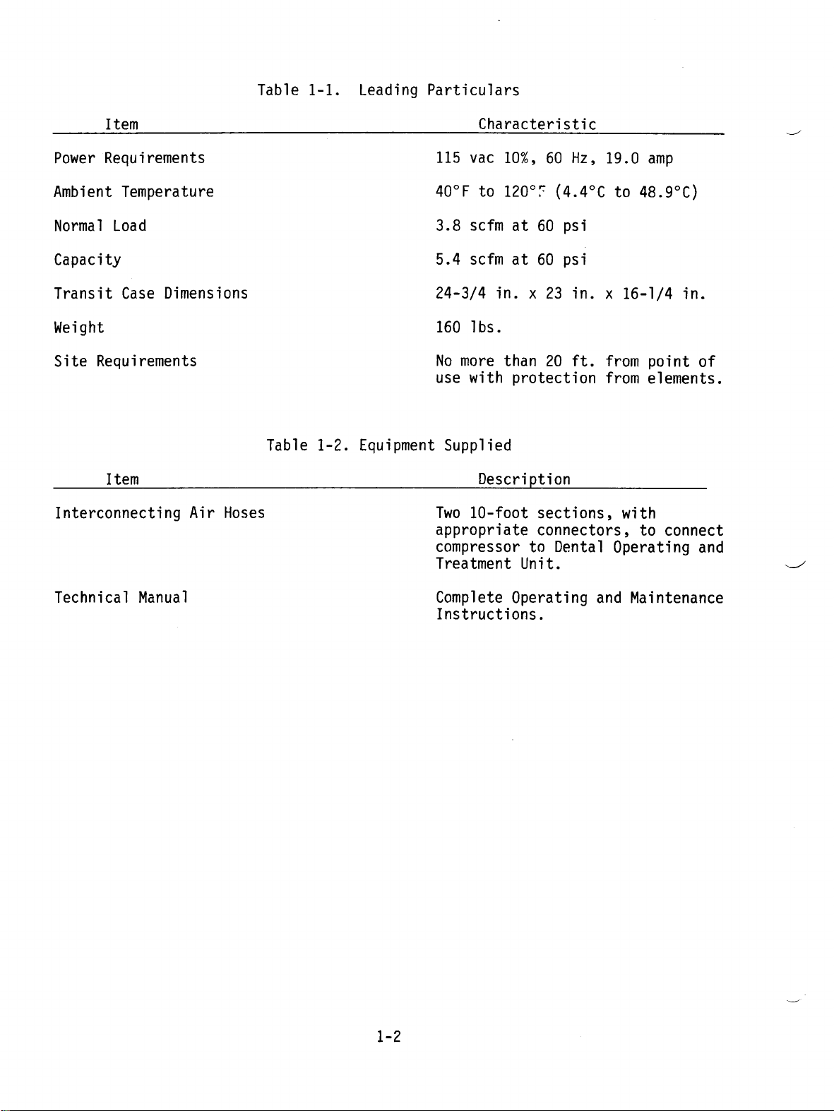
1-1.
Leading
Particulars
Item
Power
Ambient
Normal
Requirements
Temperature
Load
Capacity
Transit
Case
Weight
Site
Requirements
Item
Interconnecting
Dimensions
Air
Hoses
Table
1-2.
Equipment
Characteristic
115
vac
10%,
40°F
3.8
5.4
24-3/4
No
use
160
to
scfm
scfm
Ibs.
more
with
120°F
in. x 23
than
Supplied
Description
Two
10-foot
appropriate
compressor
Treatment
60
Hz,
(4.4°C
at
60
psi
at
60
psi
in. x 16-1/4
20
ft.
protection
sections,
connectors,
to
Dental
Unit.
19.0
amp
to
48.9°C)
from
from
point
elements.
with
to
Operating
in.
of
connect
and
Technical
Manual
Complete
Instructions.
Operating
and
Maintenance
1-2
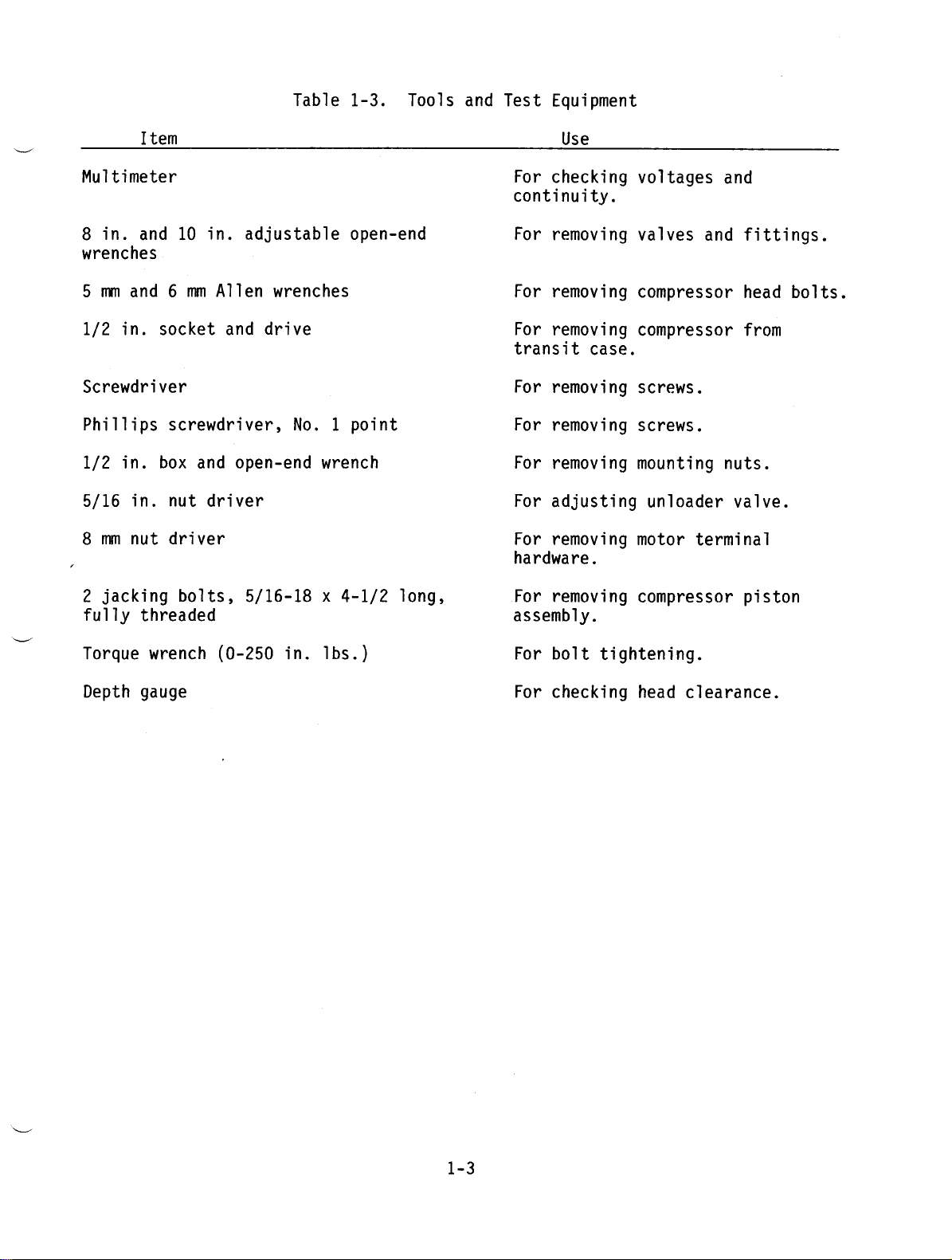
Table
1-3.
Tools
and
Test
Equipment
Item
Multimeter
8
in.
and
wrenches
5
mm
and 6 mm
1/2
in.
socket
Screwdriver
Phillips
1/2
5/16
8
mm
2
jacking
fully
screwdriver,
in.
box
in.
nut
nut
driver
threaded
10
in.
Allen
and
and
driver
bolts,
adjustable
wrenches
drive
No. 1 point
open-end
open-end
wrench
5/16-18 x 4-1/2
long,
Use
For
checking
continuity.
For
removing
For
removing
For
removing
transit
For
For
For
For
For
case.
removing
removing
removing
adjusting
removing
hardware.
For
removing
assembly.
voltages
valves
and
compressor
compressor
screws.
screws.
mounting
unloader
motor
terminal
compressor
and
fittings.
head
from
nuts.
valve.
piston
bolts.
Torque
wrench
Depth gauge
(0-250
in.
Ibs.)
For
For
bolt
tightening.
checking
head
clearance.
1-3
SECTION
II
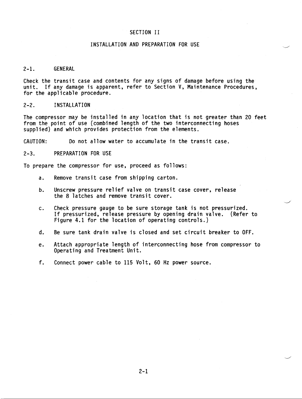
2-1.
Check
unit.
for
the
If
the
2-2.
The
compressor
from
the
supplied)
CAUTION:
2-3.
To
prepare
a.
b.
GENERAL
transit
any
damage
applicable
INSTALLATION
may
point
and
of
which
Do
PREPARATION
the
compressor
Remove
transit
Unscrew
the 8 latches
INSTALLATION
case
and
is
apparent,
procedure.
be
installed
use
(combined
provides
not
allow
FOR
case
pressure
and
contents
in
length
protection
water
USE
for
use,
from
relief
remove
AND
PREPARATION
for
refer
any
location
of
to
accumulate
proceed
shipping
valve
transit
any
to
Section
the
from
as
on
transit
cover.
signs
of
that
two
the
elements.
in
follows:
carton.
FOR
USE
damage
V,
Maintenance
is
not
before
greater
interconnecting
the
case
transit
cover,
case.
release
using
the
Procedures,
than
20
hoses
feet
c.
d.
e.
f.
Check
If
Figure
Be
Attach
pressure
pressurized,
4.1
sure
appropriate
Operating
Connect
gauge
release
for the
tank
power cable
drain valve
and
Treatment
to be
pressure
location
is
length
to
of
Unit.
115
sure
storage
by
of
operating
closed
opening
and
interconnecting
Volt,
60
Hz
tank
is
drain
controls.)
set
circuit
hose
power
source.
not
pressurized.
valve.
breaker
from
(Refer
to
OFF.
compressor
to
to
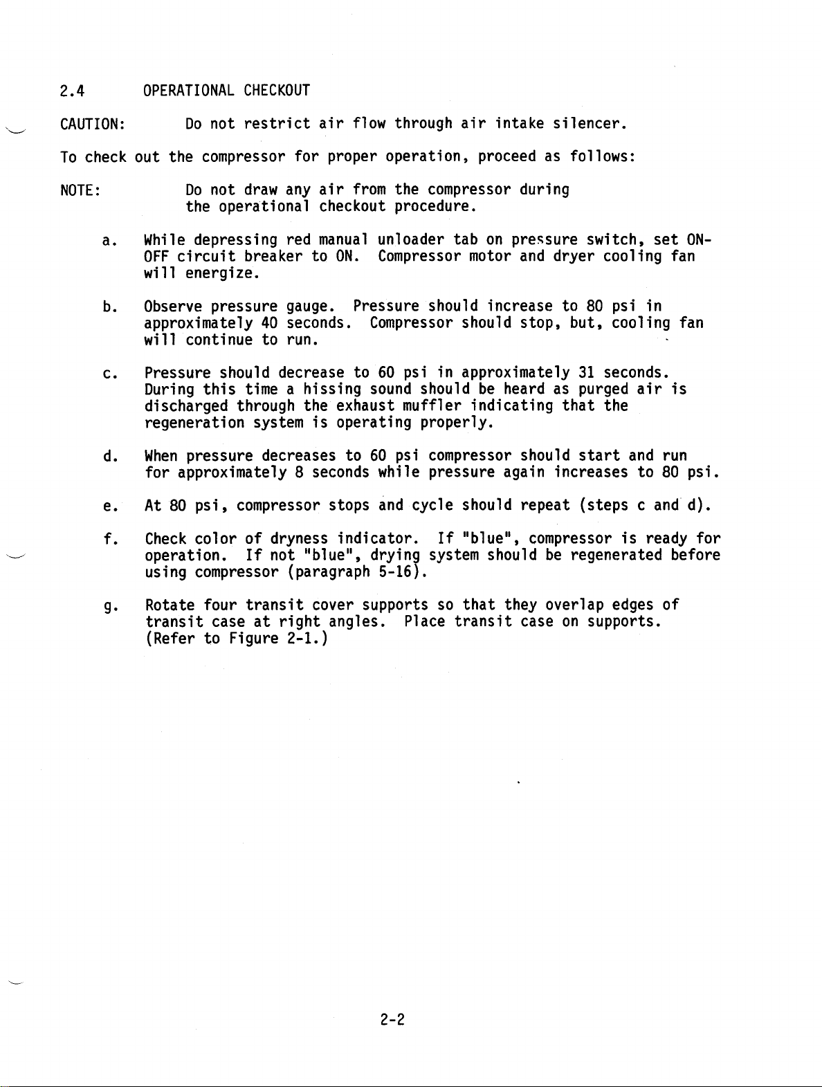
2.4
OPERATIONAL
CHECKOUT
CAUTION:
To
check
NOTE:
a.
b.
c.
d.
e.
Do
not
out
the
compressor
Do
not
the
operational
While
OFF
will
Observe
approximately
will
Pressure
During
discharged
regeneration
When
for
At
depressing
circuit breaker
energize.
pressure
continue
this
pressure
approximately
80
psi,
restrict
for
draw
any air
red
gauge.
40
seconds.
to
run.
should
through
compressor
decrease
time a hissing
system
decreases
8
air
proper
checkout
manual
to
ON.
the
exhaust
is
operating
seconds
stops
flow
operation,
from
unloader
Compressor
Pressure
Compressor
to
60
sound
to 60
while
and
through
the
procedure.
psi
muffler
psi
cycle
air
compressor
tab
should
should
in
approximately
should
properly.
compressor
pressure
should repeat
intake
proceed
during
on
pressure
motor
indicating
and
increase
stop,
be
heard
should
again
silencer.
as
follows:
switch,
dryer
to
80
but,
31
as
purged
that
start
increases
(steps c and
set
cooling
psi
in
cooling
seconds.
air
the
and
to
fan
fan
、
is
run
80
d).
ON-
psi.
f.
g.
Check
operation.
using
Rotate
transit
(Refer
color
compressor
four
case
to
of
dryness
If
not
transit
at
Figure
indicator.
"blue",
(paragraph
cover
right
angles.
2-1.)
drying
5-16).
supports
Place
If
"blue",
system
so
that
transit
compressor
should
they
case
be
regenerated
overlap
on
supports.
is
ready
edges
for
before
of
2-2
RELIEF
VALVE
AU
AAA
Pret
DIG
AFTER
LOC
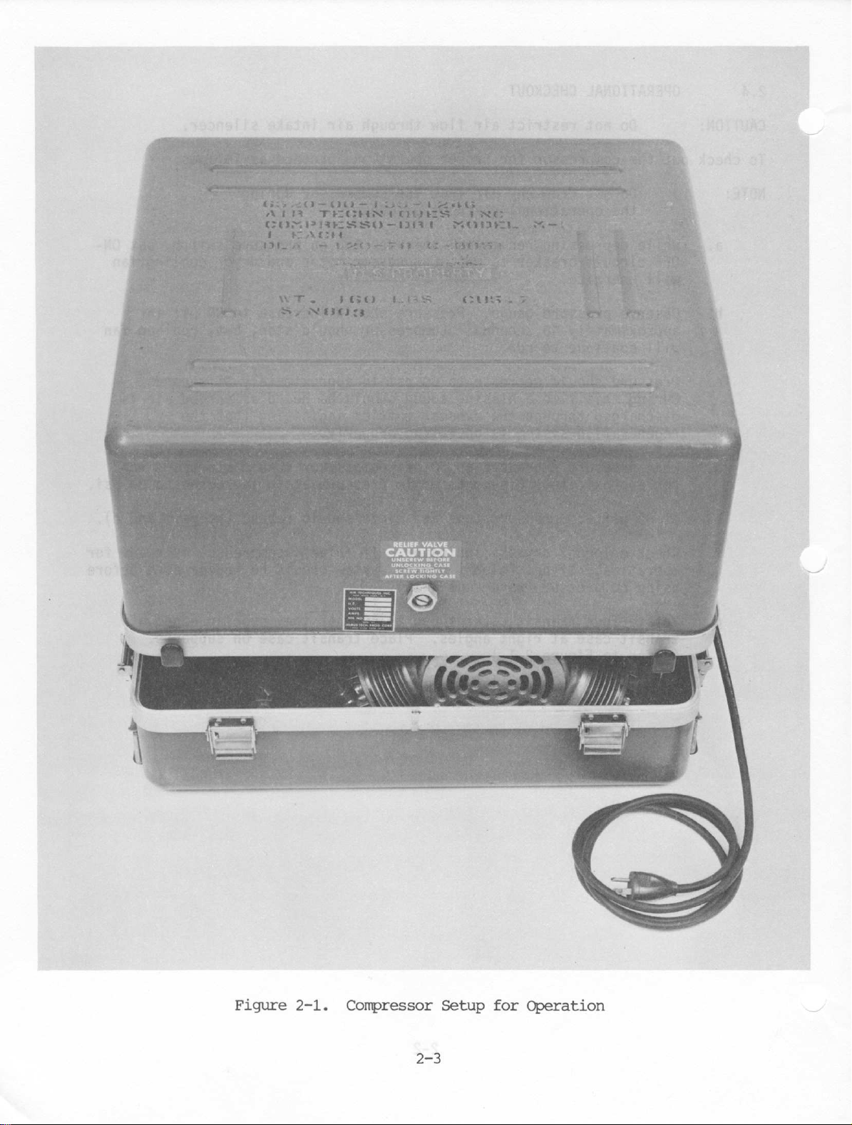
Figure
2-1.
Compressor
273
Setup
for
Operation
SECTION
III
3-1.
The
operation
the
purging
directed
chamber,
tank
the
purging
bled back
moisture
pressure
and
the
place
coil
supplied
explain
3-2.
GENERAL
through a drying
a
desiccant
reaches
through
from
in
pumping
during
fan
runs
to
these
PUMPING
(Figure
Initially,
pressure
action
compressor
compressor
flow
control
chamber
control
storage
pressure
absence
pink
for
switch
the
compressor,
chamber
with
switch
of
the
and
is
contains a desiccant
valve
tank.
within
of
moisture
wet).
opens
to
the
automatically
of
the
compressor
cycle.
During
the
chamber
removes
80
psi,
the
compressor
cycle, a portion
the
drying
the
desiccant
the
storage
cycle
operation
continuously
the
Dental
cycles
tank
begins.
of
the
and
Operating
in
detail.
CYCLE
3-1)
no
pressure
contacts
pressure
the
cooling
directed
valve
into
contains a check
The
pressure
the
tank.
in
When
the
electrical
and
opens
atmosphere.
begins.
in
switch.
through
the
the
the
storage
the
THEORY
consists
pumping
any
water
of
the
chamber.
and
carries
decreases
These
compressor.
the
and
in
the
series
When
coil
fan
the
storage
to
remove
valve
gauge
The
dryness
stored
tank
switch
unloader
This
ends
OF
OPERATION
of
cycle,
and
passes
vapor.
stops
dry
and
compressed
This
it
to
60
two
cycles
dry
compressed
Treatment
storage
with
the
the
motor
circuit breaker
start.
cooling
tank.
water
to
allow
on
the
storage
indicator
compressed
pressure
in
series
valve,
the
pumping
two
cycles,
intake
air
into a storage
When
the
the
purging
air
expanded
out
into
psi,
dry
the
the
continue
Throughout
air
Unit.
tank,
the
unloader
compressor
Compressed
coil,
As
the
mentioned
vapor
from
drying
compressed
tank
indicates
air
by
its
reaches
with
the
venting
cycle,
the
pumping
is
compressed,
tank.
pressure
cycle
in
the
storage
air
re-absorbs
atmosphere.
compressor
to
automatically
both
in
The
cycles,
the
storage
following
valve
motor
is
are
set
air
chamber,
above,
the
air.
air
to
indicates
the
color
80
(blue
psi,
compressor
the
compressor
and
the
cycle
In
in
the
begins.
When
again
the
tank
paragraphs
and
closed
to
ON,
from
and
the
drying
The
enter
the
internal
presence
for
the
pressure
motor,
and
purging
and
cooled,
the
drying
storage
During
tank
is
any
the
starts
take
cooling..
is
the
by
the
both
the
the
flow
the
or
dry,
stopping
drying
cycle
the
air
3-3.
With
the
dry
compressed
flow
control
dry
expanded
from
the
the
storage
cycle
again
operation.
PURGING
(Figure
unloader
air
valve
air
passes
desiccant,
tank
decreases
begins.
CYCLE
3-2)
valve
in
the
where
and
These
open
and
storage
it
expands
through
releases
to
60
two
the
tank
at a controlled
the
drying
it
psi,
cycles
drying
passes
into
the
repeat
3-1
chamber
through a metering
chamber,
the
atmosphere.
pressure
as
switch
long
vented
rate.
where
as
the
to
the
This
large
it
re-absorbs
When
the
closes
compressor
atmosphere,
orifice
in
volume
moisture
pressure
and
the
pumping
is in
the
of
in
UNLOADER
VALVE
MUFFLER
PRESSURE
SWITCH
ORYNESS
INDICATOR
MOTOR
INTAKE
SILENCER
COMPRESSORI
|
COOLING
COIL
FAN
To
δν
60
L2
O-
ON-OFF
MN
Hz
|
—
SWITCH
I
ee,
TOT
ALI
FLOW
VALVE
DRYING
CHAMBER
PRESSURE
CONTROL
SWITCH
COMPRESSOR
ORAIN
MOTOR
STORAGE
TANK
VALVE
PRESS
GAGE
NOTE:
FLOW
BY
URE
———O
771
|-
一
一
一
一
ARROWS.
QUICK
A
COUPLING
1
OVER
PRESSURE
RELIEF
DIRECTION
VALVE
INDICATED
STARTING
CAPACITOR
RUN
CAPACITOR
CONNECT
-一
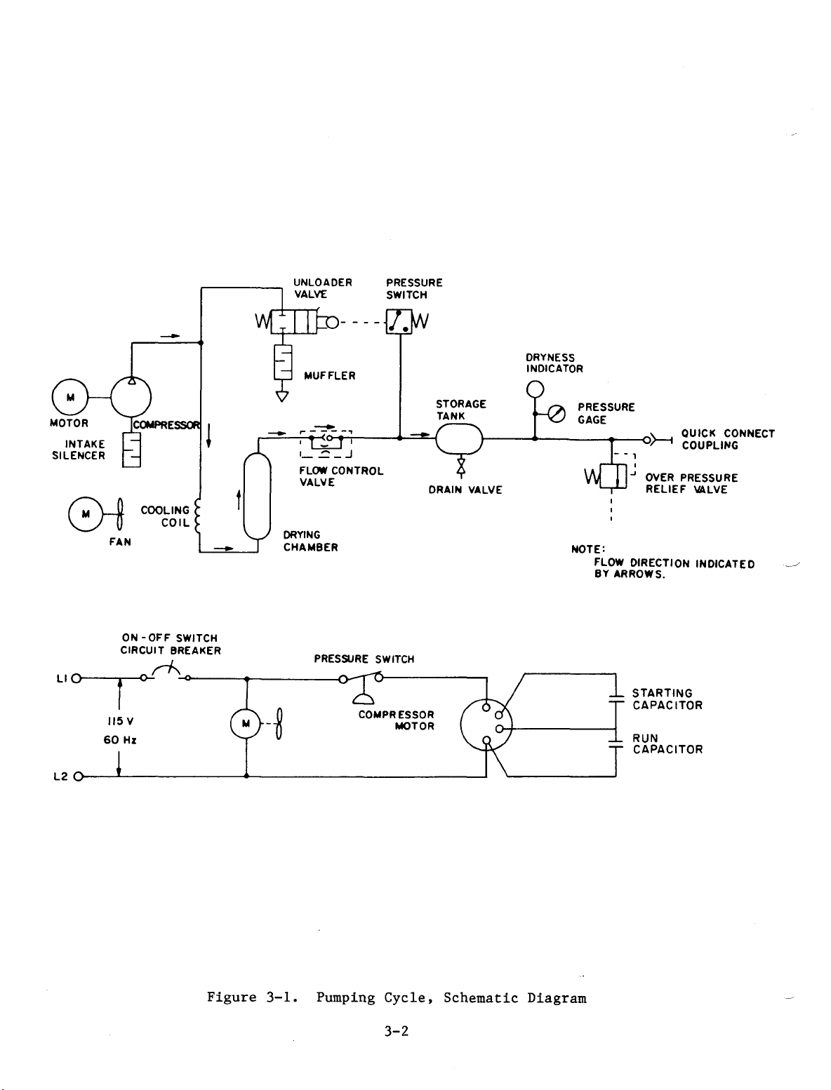
Figure
3-1.
Pumping
Cycle,
3-2
Schematic
Diagram
 Loading...