

Air 94630 PERI-PRO III User manual
Instructions
for
Peri-Pro
III
Air
Heater
CONTENTS:
Part
#
94228
30971
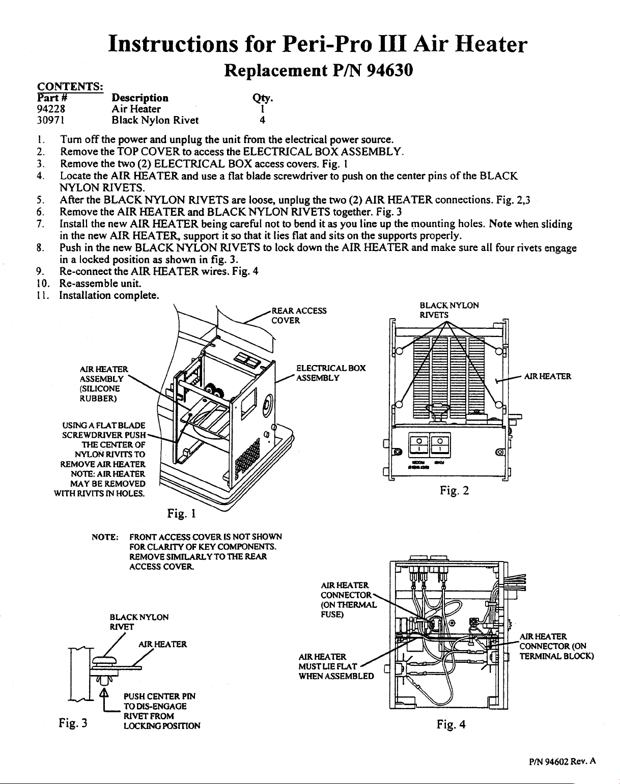
1.
Turn
2.
Remove
3.
Remove
4.
Locate
NYLON
5.
After
6.
Remove
7.
Install
in
the
8.
Push
in a locked
9.
Re-connect
10.
Re-assemble
11.
Installation
AIR
ASSEMBLY
(SILICONE
RUBBER)
Description
Air
Black
off
the
power
the
TOP
the
two
the
AIR
RIVETS.
the
BLACK
the
AIR
the
new
new
AIR
in
the
new
position
the
unit.
complete.
HEATER
Heater
Nylon
and
COVER
(2)
ELECTRICAL
HEATER
NYLON
HEATER
AIR
HEATER
HEATER,
BLACK
as
AIR
HEATER
Rivet
unplug
to
and
RIVETS
and
support
NYLON
shown
Replacement
Qty.
|
4
the
unit
from
access
the
BOX
use a flat
are
BLACK
being
careful
it
so
RIVETS
in
fig.
3.
wires.
Fig.
ELECTRICAL
access
blade
loose,
NYLON
that
4
1
the
electrical
covers.
screwdriver
unplug
RIVETS
not
to
bend
it
lies
flat
to
lock
down
REAR
ACCESS
ELECTRICAL
ASSEMBLY
P/N
power
BOX
Fig.
to
the
two
together.
it
as
and
sits
the
94630
source.
ASSEMBLY.
|
push
on
the
(2)
AIR
Fig.
you
line
up
on
the
supports
AIR
HEATER
BOX
center
HEATER
3
the
mounting
and
pins
of
the
connections.
holes.
properly.
make
sure
BLACK
NYLON
RIVETS
BLACK
Fig.
Note
all
four
2,3
when
sliding
rivets
HEATER
AIR
engage
THE
NYLON
NOTE:
MAY
.
FLAT
A
CENTER
RIVITS
AIR
AIR
BE
REMOVED
IN
NOTE:
BLACK
RIVET
fo
USING
SCREWDRIVER
REMOVE
WITHRIVITS
Fig.3
BLADE
PUSH
OF
TO
HEATER
HEATER
HOLES.
FRONT
CLARITY
FOR
REMOVE
ACCESS
NYLON
AIR
CENTER
PUSH
DIS-ENGAGE
TO
FROM
RIVET
LOCKING
Fig.
1
ACCESS
COVER
OF
SIMILARLY
COVER.
KEY
HEATER
PIN
POSITION
SHOWN
IS
NOT
COMPONENTS.
THE
TO
REAR
AIR
CONNECTOR
(ON
FUSE)
HEATER
AIR
LIE
MUST
WHEN
HEATER
ヽ
THERMAL
s
FLAT
ASSEMBLED
、|
||
dip
Ear
>
NN
Е
一
COD
.
Fig.
2
©
.
4
Fig.
Y
AIR
СОММЕСТОВ
TERMINAL
HEATER
(ОМ
BLOCK)
P/N
94602
Rev.
A
 Loading...