

Page 1
AlPHONE
COMMUNICA
TELEPHONE TYPE
MODELS TA~1 F tYPeA (single-way) TA~3F type A ¡three-way}
TA“0FtypeA (six-ivay) TA“12FtypeA (twelve-ivay)
COMMON TALK
- INSTRUCTIONS-
INTERCOM ta-FtypeA series
SELECTIVE RING
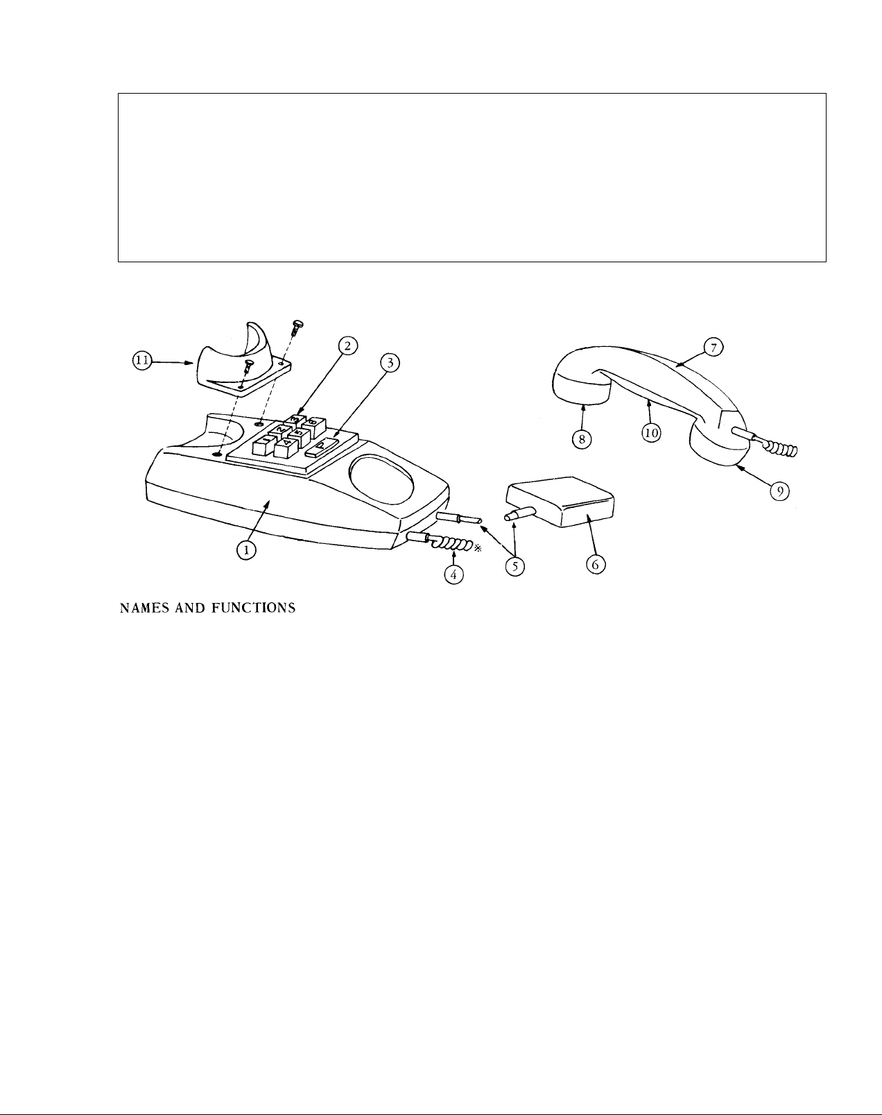
Case
Station selector buttons
Paging button
Coil cord
Terminal cord
Terminal box
(2) Handset
(^) Receiver
Microph one
Directory card
Receiver cradle for wall mounting included
SPECIFICATIONS
* Power source: DC 12 volt. Use PS—12S (PS—12C in North America) AC adaptor.
* Current consumption: 65 mA maximum at calling; 25 mA at talking.
* Calling: Push-button station selection. An electronic tone sounds when the selected station
button is depressed.
* Paging: Use PG-U type A paging adaptor in conjunction with standard paging amplifier and
speakers
* Wiring: Up to 18 conductors may be required. Please refer to wiring diagram showing system
that meets your requirements.
FEATURES
* Up to 13 selective ring stations can be connected in a system.
* Single channel common talk system. Conference calls can selectively include up to 13 stations.
* Phone designed for either desk use or wall mounting.
Page 2

* Door station TC—D type A can be installed with adaptor DF—U type A to master stations TA—3F type A , TA—6F
TYPE A, or TA—12F TYPE A. (Up to two door stations may be connected to up to 5 masters.)
* Phone system may be connected to existing paging and background music system using adaptor PG—U
TYPE A
* Talkback paging available through existing paging system using adaptor PA-B.
INSTALLATION
Do not attempt to install your intercom system until you have read and thoroughly understood the installation
procedure. Aiphone’s warranty is void if system is installed in a manner other than described in this manual.
Lay out your system in advance. Determine the exact location of each station. We recommend a full comple
ment of wire be installed, even though you may not initially be installing the maximum number of stations available
to your system. This way, should you decide to add a station later, you can avoid running additional cables to
existing stations. Do not connect wires to terminals D1 or D2 unless appropriate equipment is used. Phone system
will not operate if these wires are connected in parallel through system.
WIRING REQUIRED
TA—IF - 5 Conductors maximum TA—6F - 12 Conductors maximum
TA—3F - 9 Conductors maximum TA—12F - 18 Conductors maximum
Refer to the chart below and select the proper wire gauge to meet your requirements.
AWG WIRE SIZE 24 AWG 22 AWG
DISTANCE
DIAMETER OF WIRE
DISTANCE
1300'
0.5 mm 0.65 mm
400 m 650 m
2100'
20 AWG 18 AWG
3300' 5300'
0.8 mm 1.0 mm
1000 m 1450 m
Begin your installation with station #1. A space is provided at the left of the diagram to write in your color
code. Note the position of the C terminal at each station. Be sure you wire each station correctly.
After installing your second station we recommend that the power supply be connected to the + and - terminal
lines at a convenient location and that a test be made for calling and talking between each station. As each addi
tional station is. installed re-test between each station. Unplug power supply while making wiring connections.
ACTUAL TA-F TERMINAL LOCATIONS
TA-1Ftype a TA-3Ftype A TA-6Ftype A
P0
D2
0
di<2
30
20
,0
c0
-0
+ 0
6 0 P0
50
40
30
20
,0 +0
D20
D10
C0
_0
TA-12FtypeA
60
120
50
110D20
40
1Q0D10
30 90
80
20
10
70+0
(T) — @ ; for connecting relative stations
P0
(+)—©: for power supply
© : for receiving call and talking
@ — @ ; for connecting door station
c0
_0
0 : for paging
INSTALLATION FOR WALL MOUNTING
1) Attach the mounting bracket to wall or
single gang plaster ring.
2) Attach handset cradle included , as shown in
illustration.
EQUIPMENT AVAILABLE FOR USE WITH YOUR TA-F type A PHONE SYSTEM
TA-IF TYPE A ; 1 call master station with
paging button.
^ TA-3F TYPE A ; 3 call master station with
paging button and door station capability.
TA-6F TYPE A : 6 call master station with
paging button and door station capability.
■
P
TA—12F TYPE A ; 12 call master station
with paging button and door station
capability.
TC D Type A: Surface or semi-flush mount
door station with push button for calling
connected master.
DF—U TYPE A: Adaptor for door station.
Required between door station TC—D type A
and TA—F type A stations.
Page 3
SP—3: Paging speaker. Complete and
^ ready to install including round flush
mounting frame. Transformer installed
for 70V line operation.
(Not available in North America)
PG-U TYPE A: Paging adaptor for
connecting any amplifier and background
music source to your TA—E system.
Features paging volume, treble & bass
controlsand automatic background music
N—S: Square frame for SP —3 speaker.
.A, N—E: Round surface frame for SP—3
speaker.
PS-12C: CSA & UL LISTED power sup
111"
ply (available only in North America).
RY — AC TYPE A ; Relay for operating
.V external device such as additional calling
buzzer or bell, door release, etc.
TA-6F TYPE A: WITH TWO DOOR STATIONS CONNECTED.
TC-D TYPE A
STATION
STATION
STATION
PS-12S: Power supply for system.
Standard everywhere except in North
America.
EL—9S: Electric door release. Requires
separate transformer and RY—AC.
I.
PA-B: Talkback paging adaptor.
NCH-l;Noise cancelling handset espe
cially designed to allow AiphoneTA-F
phone system to operate in extremely
noisy areas. Field installed only.
STATION
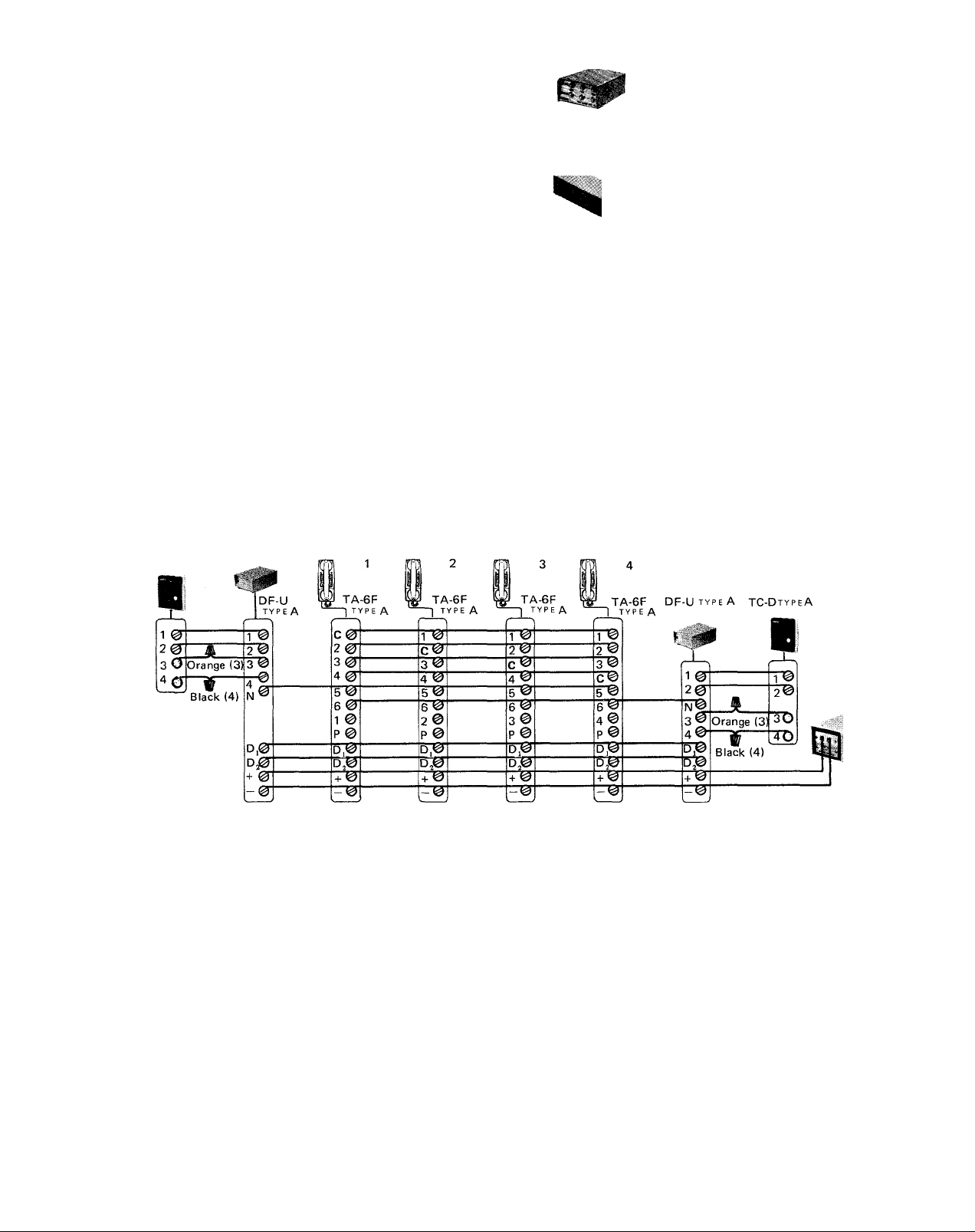
NOTE; 1. Example above shows 4TA—6F t yi>e A phones. 1 additional phonemay be added if required.
2. Maximum of 2 door stations may be connected to up to 5 phones per system.
3. Do not use terminal #1 on each phone for communication with door station.
OPERATION: When call tone is heard at master, lift handset and press button No. 4 (or No. 5)
once and begin conversation.
PS-12S
or
PS-12C
Page 4

TA-12F TYPE A ALL MASTE
TA-12F tvpeA phone system with PAGIN(
Page 5

R PHONE SYSTEM
STATION STATION
8
B
B
0
STATION
9 10
7^
7^
w
7»
To^
P0
Dl«
D2 ^
7^
7^
7^
STATION
11
STATION
12
Tgr
6 ^
7^
7®r
12
"W
7^
r0
PS-12S or
PS-12C
>'
and BACKGROUND MUSIC SYSTEM
Page 6

TA-6F TYPE A SYSTEM WITH DOOR STATION & ELECTRIC DOOR RELEASE
TC-D TYPE A
■
1 0^
2 0l
Orange (3)
3 O’
[4cr
Black (4)
0
|df-u
1 ^
2 C)
T©
STATION
1
TA-6F
>
C 0"
2 0"
3 0^
4 0"
5^ 5 <0
6 ©■
1 ©
P ©
STATION
TA-6F
T©|
c
3 ©
4 (3
FO"
2 ©
P ©
2
STATION
3
TA-6F
1
T©"
c ©
STATION
A
TA-6F
1 '0
2 ©
3 ©
c©
b © 5 ©
6 ©
3©
p ©
e"©"
4 ©
p @
Example
phones,
may be
5 allows
station.
release.
shows 4 TA—6FType A
One additional phone
added if required. Button
conversation with door
Button 6 operates door
PS-12C
or
PS-12S
- 0
Dj0
+ © + ©
-©
+ © + ©
WIRING DOOR RELEASE EL-9S
TA-F TYPE A INTERCOM SYSTEM WITH TALKBACK PAGING
D]©
k
___
BLACK
^
BELL
TRANSFORMER
FOR DOOR
LOCK
AVAILABLE CYLINDRICAL LOCKS
EQUIPMENT REQUIREMENTS
1) TA — F system shall consist of TA —3F, TA —6F or TA—12F phones. TA—IF will not operate with
talkback paging adaptor PA — B.
2) One PS 12C, one PG U type A, one PA — B, one paging amplifier with 70 volt line and output of less
than 50 watt RMS, and appropriate paging speakers as required must be used.
3) Door station adaptor DF—U typeA and TC—D typeA door station can not be included in system when
installing talkback paging adaptor PA—B.
For the full information, please refer to PA-B instruction sheet.
Page 7
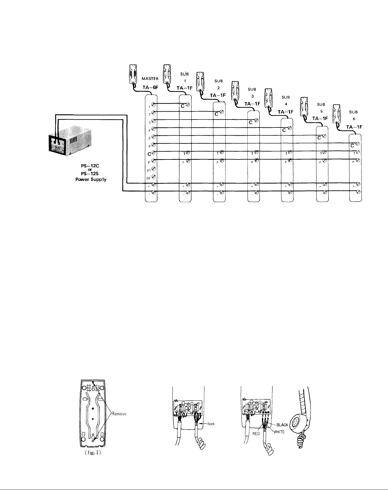
MASTER/SUB SYSTEM
Any combination of TA—F series phones can be intermixed to develop a master-sub system to meet your
requirements. The example below shows 6 TA—IF stations connected to 1 TA—6F.
All stations have paging ability. Refer to paging diagram for proper connection to paging system.
FIELD INSTALLATION OF NOISE CANCELLING HANDSET MODEL NCH-1
For extremely noisy areas, Aiphone has developed a special handset which allows excellent communication
from a phone in a noisy area to other phones in the communication system. Designed to work
with Aiphone Model TA-F, this handset contains an amplifier for communication and noise cancelling
mouthpiece.
TO INSTALL
Remove two screws on bottom of phone as shown, using a Phillips screw driver, (fig. 1)
(a)
Carefully lift the plastic case from the base.
(b)
Lift hook anchoring coil cord to metal base. (fig. 2)
(c)
Carefully remove red, white and black wires from printed circuit board using soldering iron.
(d)
Remove old handset, and retain for spare parts.
Attach red, white and black wires from noise cancelling handset coil cord with soldering iron as shown.
(e)
Be sure your wires are in the correct order, (fig. 3)
Bend hook back, (Note (c)), replace plastic case (Note (b)), and screws (Note (a)).
(f)
Page 8

INSTALLING EXTERNAL SIGNALING DEVICE RELAY
Example shows station 4 with relay RY—AC which switches an external light, bell, horn or buzzer (external
signal devices not provided by Aiphone).
* Calling:
Pick up the handset and momentarily depress the selector button of desired station.
* Receiving:
An incoming call is announced by an electronic tone. Pick up the handset and begin speaking.
EXTERNAL SIGNALING DEVICE
NOT TO EXCEED 2 A 250 V
PAGING OPERATION
* Pick up the handset and make announcement by pushing and holding the paging button. Background music will
automatically cut out during paging operation.
CLEANING YOUR INTERCOM STATIONS
* Your Aiphone intercom stations may be cleaned with a soft cloth dampened with household cleanser, such as Mr.
Clean or Fantastik.
We at AIPHONE are proud of our products. Our designers and engineers strive to bring you the finest in
communication equipment. Each item has been carefully tested and inspected before leaving our factory. Properly
installed and used, your Aiphone intercom system should give years of trouble-free service.
We are pleased to offer the following warranty:
Aiphone vvarrants its products to be free from defects of material and workmanship under normal
use and service for a period of one year after delivery to the ultimate user and will repair free of
charge or replace at no charge, should it become defective upon which examination shall disclose
to be defective and under warranty. Aiphone reserves unto itself the sole right to make the final
decision whether there is a defect in materials and/or workmanship; and whether or not the prod
uct is within the warranty.
This warranty shall not apply to any Aiphone product which has been subject to misuse, neglect,
accident, or to use in violation of instructions furnished, nor extended to units which have been
repaired or altered outside of the factory.
This warranty does not cover batteries or damage caused by batteries used in connection with the
product.
This warranty covers bench repairs only, and any repairs must be made at the shop or place des
ignated in writing by Aiphone. Aiphone will not be responsible for any costs incurred involving on
site service calls.
* * ♦
WARRANTY
Aiphone Co., Ltd., Nagoya, Japan
Aiphone U.S.A., Inc,, Bellevue, Washington
TA-Fl-0278tH)
ALL OVER THE WORLD
AIPHONE
Printed in Japan
 Loading...