

Page 1
AlPHONE
COMMUNICA
TELEPHONE TYPE INTERCOM
MULTI-CHANNEL SEMI PRIVATE SYSTEM
MODELS TA-12H TYPE A Uwelve-way)
TA-24H TYPE A (twenty-four way)
- INSTRUCTIONS-
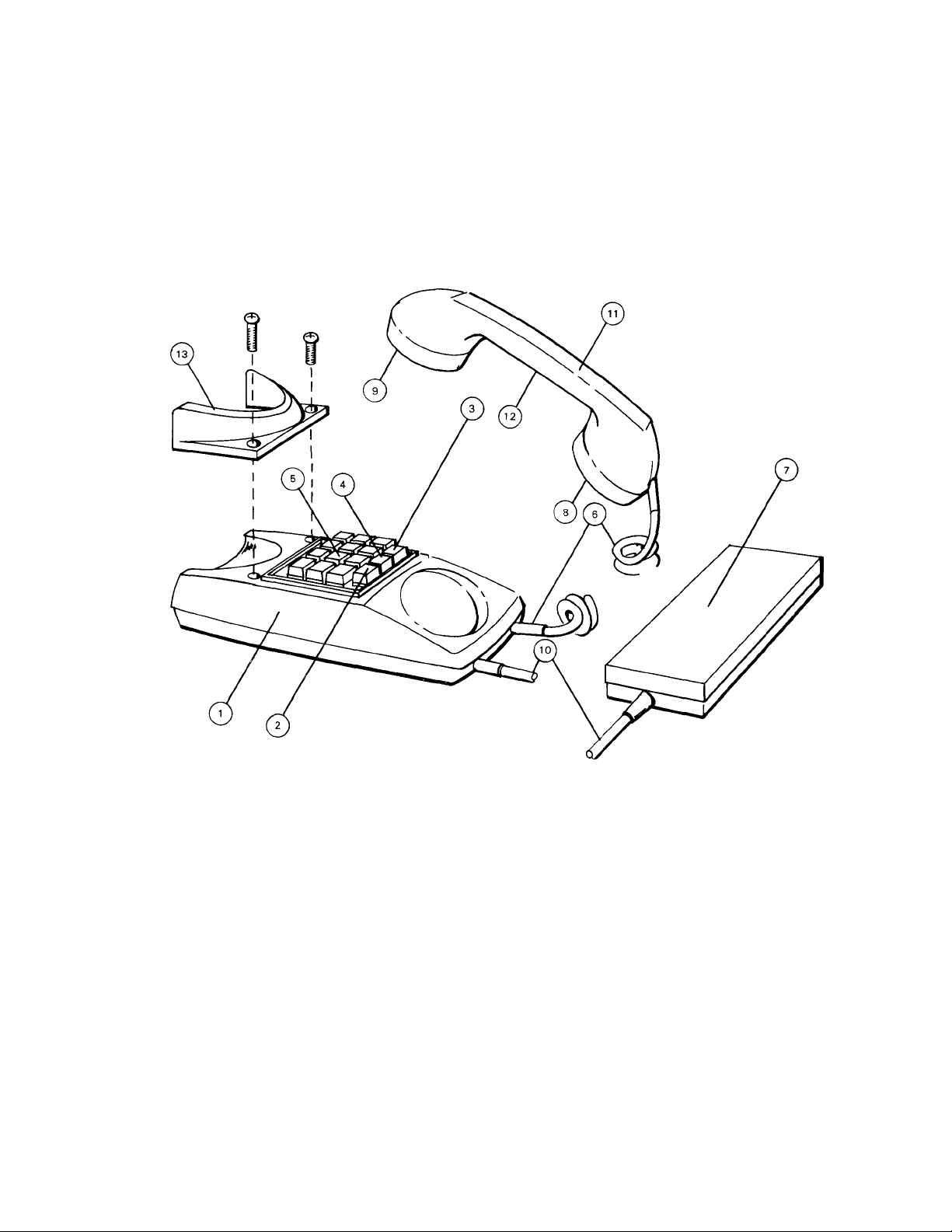
NAMES & FUNCTIONS
0 Body
(0 Call button switch (C)
(0 Change over button (A) (only in TA—24H)
(0 Paging button (P)
(0 Station selector buttons
(0 Coil cord
(0 Terminal box (Junction box)
SPECIFICATIONS:
* Wiring:
* Power source:
Current consumption: 65 MA maximum at calling; 25 MA at talking.
* Calling:
* Paging:
USE PARALLEL CONDUCTORS, NOT TWISTED PAIRS.
Up to 30 conductors may be required. Please refer to wiring diagram showing system
that meets your requirements.
DC 12 volt. Use PS—12S (PS—12C in North America) AC adaptor.
Push-button station selection. An electronic tone sounds when, after the selected sta
tion button is depressed, the call button (C) is depressed.
Use PG-U paging adaptor in conjunction with standard paging amplifier and speakers
(0 Microphone
(0 Receiver
(0 Terminal cord
Handset
(0 Directory
(0 Receiver cradle for wall mounting^
included
Page 2
FEATURES
* As many as 12 simultaneous conversations are possible with a 24 station system.
* Conference calls can selectively include up to all stations in the system.
* Designed for either desk use or wall mounting.
»Any station can page through connected conventional paging or background music system using adaptor PG-U.
* Block paging and talkback paging is available when using adaptor PA-B.
* TA—12H and TA—24H phones can be intermixed to provide a communication system to meet your requirements.
INSTALLATION
Do not attempt to install your intercom system until you have read and thoroughly understood the installation
procedure. Aiphone’s warranty is void if system is installed in a manner other than described in this manual.
Lay out your system in advance. Determine the exact location of each station. We recommend a full comple
ment of wire be installed, even though you may not initially be installing the maximum number of stations available
to your system. This way, should you decide to add a station later, you can avoid running additional cables to
existing stations. Do not connect wires to terminal P3 unless appropriate equipment is used. Phone system will
not operate if this wire is connected in parallel through system.
WIRING required: uSE PARALLEL CONDUCTORS, NOT TWISTED PAIRS.
TA-12H - 18 Conductors maximum TA-24H - 30 Conductors maximum
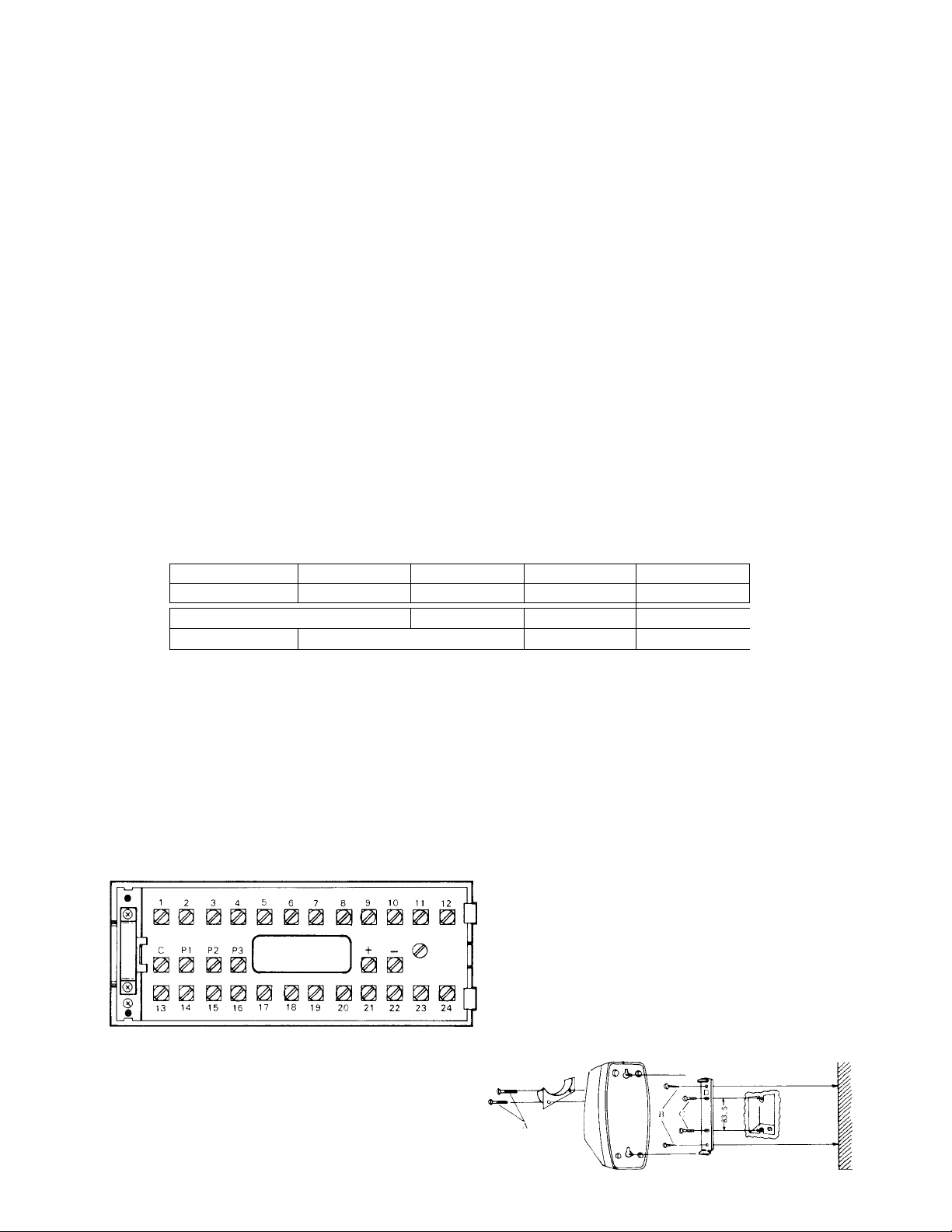
Refer to the chart below and select the proper wire gauge to meet your requirements.
AWG WIRE SIZE 24 AWG
DISTANCE 1300'
DIAMETER OF WIRE 0.5 mm
DISTANCE
390 m
22 AWG 20 AWG
2300'
0.65 mm
700 m
3300' 5000'
0.8 mm 1.0 mm
1000 m 1600 m
18 AWG
Begin your installation with station #1. A space is provided at the left of the diagram to write in your color
code. Note the position of the C terminal at each station. Be sure you wire each station correctly.
After installing your second station we recommend that the power supply be connected to the + and - terminal
lines at a convenient location and that a test be made for calling and talking between each station. As each addi
tional station is installed re-test between each station. Unplug power supply while making wiring connections.
To obtain the most efficiency from your power supply it is necessary to install the unit as near as possible
to the center of your communications network.
ACTUAL TA-24H TYPE A TERMINAL LOCATIONS
O- (^2^ : for connecting relative stations
: for power supply
: for receiving calls and talking
0 - : for paging
INSTALLATION FOR WALL MOUNTING
1) Attach the mounting bracket to wall or
single gang plaster ring.
2) Attach handset cradle included as shown in
illustration.
fps) : for local speaker cutout
Page 3
EQUIPMENT AVAILABLE FOR USE WITH YOUR TA-H PHONE INTERCOM SYSTEM
dP
TA—12H; Type A. 12 call master station.
Up to 13 masters may be connected.
TA—24H: Type A. 24 call master station.
Up to 25 masters may be connected.
PS—12C: CSA & UL LISTED power sup
ply (available only in North America),
PS—12S: Power supply for system.
Standard everywhere except in North
America.
PA —B: Talkback paging and/or block
paging adaptor. Use with PG—U and paging
amp.
RY — AC TYPeA : Relay for operating
external device such as additional calling
buzzer or bell, door release, etc.
RY-P: Relay for local speaker cut out.
Local speaker cut out elimi nates the
chance of feed back if a paging speaker
is located near station initiating paging
call.
f*
SP—3: Paging speaker. Complete and
^ ready to install including round flush
mounting frame. Transformer installed
fot 70V line operation.
(Not available in North America,!
N—S: Square frame for SP —3 speaker.
N—E: Round surface frame for SP—3
speaker.
PG—U TYPE A ; Paging adaptor for con
necting any amplifier and background
music source to your TA—H system. Fea
tures separate volume, treble & bass con
trols for paging and background music. In
cludes automatic background music
cutout.
NCH-l;Noise cancelling handset espe
cially designed to allow Aiphone TA-H
phone system to operate in extremely
y
noisy areas. Field installed only.
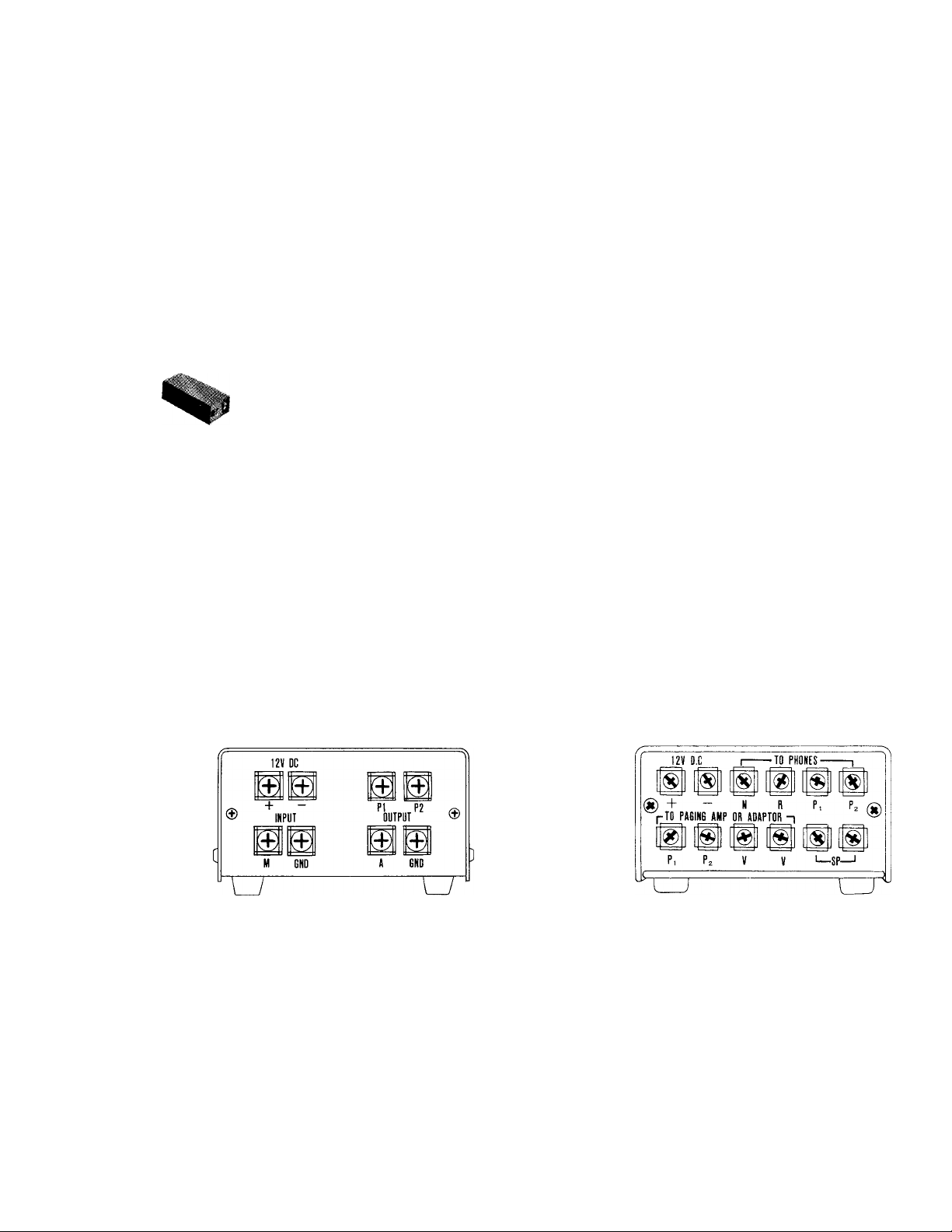
ACTUAL PG-U
• 0
© '
(L) '
• ®
(g) • GND i for background music source
■ GND : for
@ ■
: DC
i for paging(connect to phones)
A TERMINAL LOCATIONS
TYPE
power connections
paging amplifier
ACTUAL PA-B TERMINAL LOCATIONS
i DC power connections
©
© ■
® ■
© ■
® ■
■ @
• ®
■ ®
! Block selection terminal
(®
; All call terminal
®
'. TO PHONES for paging input
: TO ADAPTOR for paging output
: 70V line input terminal
to paging speakers.
Page 4

TA-H TYPE A ALL M)
TA-H ALL MASTER SYSTEM MAi' BE
STATION
STATION
STATION
STATION
STATION
STATION
STA'
TO ADDITIONAL PAGING SPEAKERS
4
Page 5

iSTER SYSTEMS with PAGING USING AlPHONE PG-U PAGING ADAP'
CONNECTED TO EXISTING PAGING OR BACKGROUND MUSIC SYSTEMS BY USING PS-12C POWER SUPPLY AND PAGIf
ION
STATION
STATION
STATION
STATION
STATION
STATION
STATION STATION STATION
STATIOI
Page 6

rOR
IG ADAPTOR PG-U
STATION
STATION
STATION
STATION
STATION
STATION
STATION
STATION
Page 7

PAGING THRU EXISTING PAGING OR MUSIC SYSTEMS
To operate properly with the PG—U adaptor the
existing amplifier and background music source should
meet the following requirements:
Amplifier Input Requirements
Aux; 100K- 500K n ; 0.12V-0.5V
Phono: lOOK - 500K ; 0.12 V - 0.5 V
Microphone: DO NOT USE Microphone Input
Tuner Output Requirements
Use audio output.
Range: lOOMV — 1.2V; lOK Q or less
Tape Output Requirements
Use low level output.
Range: lOOMV - l.OV; 600 S2
FIELD INSTALLATION OF NOISE CANCELLING HANDSET MODEL NCH-1
For extremely noisy areas, Aiphone has developed a special handset which allows excellent communication
from a phone in a noisy area to other phones in the communications system. Designed to work
with Aiphone Model TA-H, this handset contains an amplifier for communication and noise cancelling
mouthpiece.
TO INSTALL
(a) Remove two screws on bottom of phone as shown, using a Phillips screw driver, (fig. 1)
(b) Carefully lift the plastic case from the base.
(c) Lift hook anchoring coil cord to metal base. (fig. 2)
(d) Carefully remove red, white and black wires from printed circuit board using soldering iron.
Remove old handset, and retain for spare parts.
(e) Attach red, white and black wires from noise cancelling handset coil cord with soldering iron as shown.
Be sure your wires are in the correct order, (fig. 3)
(f) Bend hook back, (Note (c)), replace plastic case (Note (b)), and screws (Note (a)).
Remov e
: fig. 1 )
Page 8

INSTALLING PAGING SPEAKERS
1) For ceiling or wall mounting cut hole according to type of speaker chosen.
2) Install mounting hardware with screws provided. For mounting on concrete or other hard surface use suitable
anchors for attaching mounting frame.
3) A single pair of wires to paging amplifier.
4) Attach speaker to mounting frame by inserting studs into slots of mounting frame, aligning red arrow on baffle
with ted screw and turning baffle counterclockwise until properly locked.
SP-3 SP—3 w/NS frame
SP-3
Note: Aiphone SP—3 comes complete with baffle and mounted transformer.
ACTUAL TRANSFORMER TERMINAL LOCATION ON SP-3.
)3 (0.5 Watt)
SP-3
) 2 (1 Watt)
M (1.5 Watt)
I 0 (Com.)
SP—3 w/NE frame
SP-3
Wire paging speakers referring to the table shown below. Total output of speakers must not be mote than
the rated output of the paging amplifier used.
RATED TRANS
FORMER OUTPUT
SP-3 VA watts
@ 70,7 V LINE
TERMINAL CONNECTION SPEAKER OUTPUT
0 - 3 (10 K ohms) 0.5 watt
0 - 2 ( 5 K ohms)
0 - 1 (3.3 K ohms) 1.5 watt
70.7 V LINE
1 watt
PAGING WIRING REQUIREMENTS:
a) 4 wires between PG-U adaptor and TA-H stations.
b) 4 common wires plus number of installed stations between TA-H stations.
c) A single pair of wires between PG-U adaptor and paging amplifier.
d) A single pair of wires between paging amplifier and paging speakers.
Page 9

TALKBACK PAGING AND BLOCK PAGING
USING ADAPTOR PA-B
EXAMPLE #1
1) Up to 10 block or talkback paging areas may be in
stalled with a system.
For complete and comprehensive installation infor
mation see instructions packed with PA—B.
2) Amplifier with 70V line output must be used with
adaptor PA—B.
3) One potential phone must be deducted for each PA—B
installed. (If all call is required one additional po
tential phone must be deducted.
Example #1 shows 3 areas of talkback paging and
all call. Selector button #9 on each phone operates
block #1. Button #12 is used for calling all 3 blocks
simultaneously.
Example #2 illustrates single talkback paging cir
cuit.
Example #3 illustrates connection if block paging is
desired but without talkback. One amplifier, one
PA—B and one PG—U per block is still required even
though talkback is not required.
4) Individual block or area paging with or without
talkback is available with this system.
5) Vou may page one area, any number of areas, or
all areas by deprssing the appropriate selector
button, then the page button. Make your announcement,
then release page button to listen for reply.
STATION STATION
8 9
BACKGROUND
MUSIC
SOURCE
BLOCK #1
PG-U A
BLOCK #2
PG-U TYPE A
BLOCK #3
PG-U TYPE A
6) One PG-U, one PA-B and one paging amplifier
is required for each area.
7) THIS IS A MULTI-CHANNEL SYSTEM BETWEEN
TELEPHONE MASTER STATIONS; HOWEVER,
THE BLOCK PAGING CIRCUITS ARE COMMON
TALK MEANING ONLY ONE MASTER MAY PAGE
AT A TIME.
EXAMPLE #2
BLOCK AND TALKBACK PAGING CIRCUIT
EXAMPLE #3
BLOCK PAGING CIRCUIT (NO TALKBACK)
Page 10

INSTALLING EXTERNAL SIGNALING DEVICE RELAY
Example shows station 4 with relay RY-AC which switches an external light, bell, horn or buzzer (external
signal devices not provided by Aiphone).
* Calling:
Pick up the handset and depress the selector button of desired station, then momentarily depress call button.
* Receiving:
An incoming call is announced by an electronic tone. Pick up the handset and begin speaking.
EXTERNAL SIGNALING DEVICE
NOT TO EXCEED 2A, 250 V
PAGING OPERATION
* Pick up the handset and make announcement by pushing and holding the paging button. Background music will
automatically cut out during paging operation. For block paging or talkback paging depress station selector but
ton, then press and hold paging button. For paging talkback release paging button.
CLEANING YOUR INTERCOM STATIONS
* Your Aiphone intercom stations may be cleaned with a soft cloth dampened with household cleanser, such as Mr.
Clean or Fantastik.
We at AIPHONE are proud of our products. Our designers and engineers strive to bring you the finest in
communication equipment. Each item has been carefully tested and inspected before leaving our factory. Properly
installed and used, your Aiphone intercom system should give years of trouble-free service.
We are pleased to offer the following warranty:
♦ *
WARRANTY
Aiphone warrants its products to be free from defects of material and workmanship under normal
use and service for a period of one year after delivery to the ultimate user and will repair free of
charge or replace at no charge, should it become defective upon which examination shall disclose
to be defective and under warranty. Aiphone reserves unto itself the sole right to make the final
decision whether there is a defect in materials and/or workmanship; and whether or not the prod
uct is within the warranty.
This warranty shall not apply to any Aiphone product which has been subject to misuse, neglect,
accident, or to use in violation of instructions furnished, nor extended to units which have been
repaired or altered outside of the factory.
This warranty does not cover batteries or damage caused by batteries used in connection with the
product.
This warranty covers bench repairs only, and any repairs must be made at the shop or place des
ignated in writing by Aiphone. Aiphone will not be responsible for any costs incurred involving on
site service calls.
lijU.
JTJJJTJjrJTJrrT Twwwrirwww-r^.
Aiphone Co., Ltd., Nagoya, Japan
Aiphone U.S.A., Inc., Bellevue, Washington
TA-HI-0278©
ALL OVER THE WORLD
AIPHONE
PRINTED IN JAPAN
 Loading...