

Page 1
0407
Provided by Aiphone
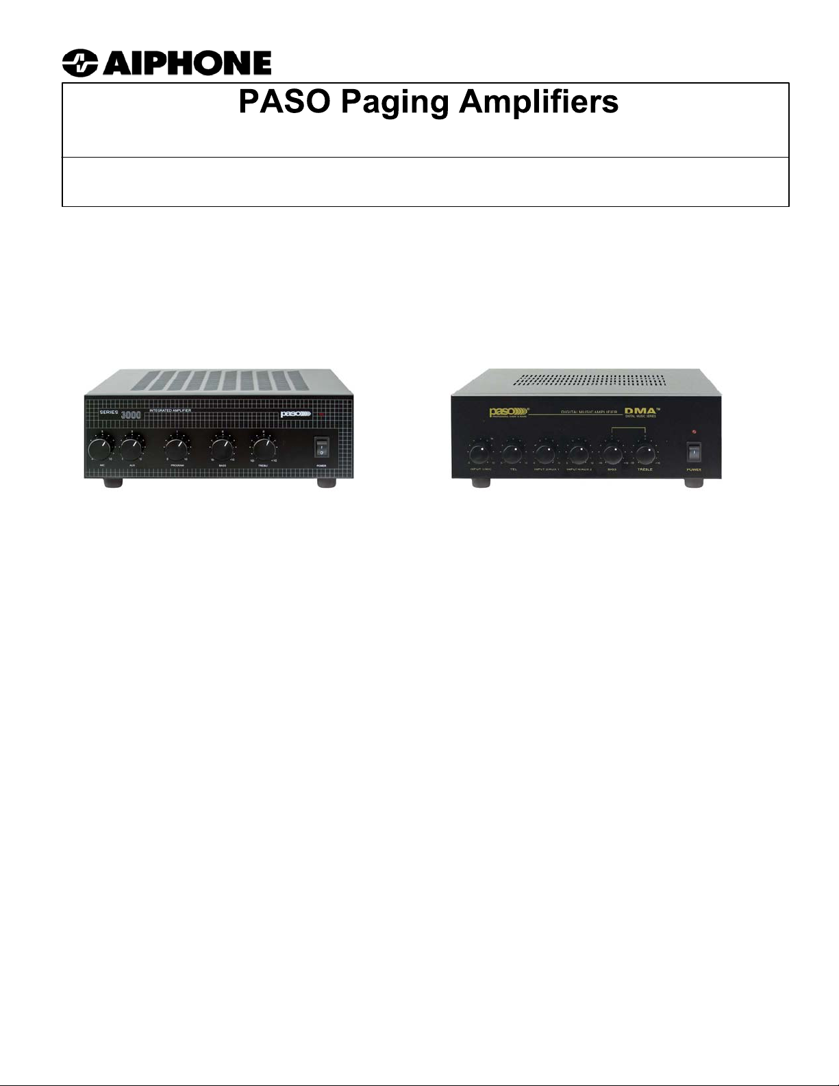
T3115BGM (15W); T3130BGM (30W); DMA2060 (60W); DMA2120 (120W)
- Supplemental Wiring Instructions for connecting with Aiphone Systems -
Aiphone offers a series of Paging Amplifiers to provide paging and other features for many of our systems.
These amplifiers are manufactured by PASO, and are available in 15, 30, 60, and 120 Watt sizes. When
adding background music to the NEM system, Group Call or All Call to the AI-900 system, or paging to a
large variety of other Aiphone systems, these amplifiers are tested and approved. This supplemental
instruction manual includes wiring diagrams for applications with Aiphone systems. See PASO Installation
& Operation Manual included with the product for complete information on these products.
15 and 30 Watt Amplifiers
60 and 120 Watt Amplifiers
AVAILABLE MODELS WATTAGE APPLICATIONS
T3115BGM 15 Watts - Background Music for NEM System
- Paging & Background Music
T3130BGM 30 Watts - All Call & Group Call for AI-900 System
- Paging & Background Music
DMA2060 60 Watts - Paging & Background Music
DMA2120 120 Watts - Paging & Background Music
When using the above Amplifiers for Paging via an Aiphone system, match the appropriate
paging adaptor with the system being used. Choose the amplifier based on input and output
requirements for your application.
PAGING ADAPTOR SYSTEM
AXW-PA1 AX
BA-1 LEM, LEF, LAF-C/CA, LDF-C/CA, NEM, NDR, NDRM
BA-1P AP-M, MP-S
MC-A/A MC-60/4A
PD-1 TD-H
PD-2 (w/Talkback) TD-H
YAW-R/B YAZ
Page 2
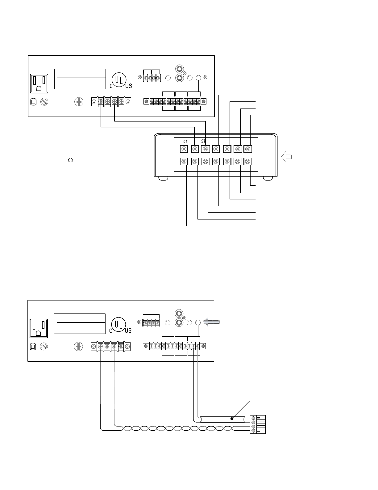
WIRING DIAGRAM
T3115BGM with the NB-U for Background Music for NEM System:
AUX
47K ohm 100mv
IN PARALLEL
600 ohm
8 ohm
117V~500W MAX
UNSWITCHED
LINE FUSE
2A 250V
paso
GROUND
COM 8 25V 70V
1 VOLT
UNMUTE G MUTE
MOH
1 WATT
OUTPUT LEVEL
10K ohm
1 V
PROGRAM MIC TEL(PAGING)
G COM HOT G COM HOT G COM HOT
BALANCED BALANCED BALANCED
250 ohm
1 mv
8
AUX
ATTENUATOR
TEL(PAGING)
OUTPUT LEVEL
600 ohm
100 mv
63
A1 A2 A3 A4
To A1 on NEM/NDR/NDRM Master
To A2 on NEM/NDR/NDRM Master
To A3 on NEM/NDR/NDRM Master
To A4 on NEM/NDR/NDRM Master
Tie the 25V output of the amplifier
to the 63
input of the NB-U.
BGM
V4V3V2V1EYB
WIRING DIAGRAM
T3130BGM with the AI-900RS for Group Call / All Call on the AI-900 System
Include one T3130BGM for each AI-900RS card in the sytem where sub stations require
Group Call or All Call.
AUX
47K ohm 100mv
IN PARALLEL
MOH
OUTPUT LEVEL
AUX
ATTENUATOR
600 ohm
250 ohm
10K ohm
1 mv
1 V
PROGRAM MIC TEL(PAGING)
TEL(PAGING)
OUTPUT LEVEL
100 mv
Adjust TEL (PAGING) OUTPUT LEVEL
accordingly to obtain optimum output
117V~500W MAX
UNSWITCHED
paso
COM 8 25V 70V
600 ohm
1 VOLT
8 ohm
1 WATT
NB-U
To V4 on NEM/NDR/NDRM Master
To V3 on NEM/NDR/NDRM Master
To V2 on NEM/NDR/NDRM Master
To V1 on NEM/NDR/NDRM Master
To E on NEM/NDR/NDRM Master
To Y on NEM/NDR/NDRM Master
To B on NEM/NDR/NDRM Master
Page 2
LINE FUSE
2A 250V
GROUND
COM
25V
G COM HOT G COM HOT G COM HOTUNMUTE G MUTE
BALANCED BALANCED BALANCED
TEL(PAGING) “COM”
TEL(PAGING) “HOT”
1 Core Shielded Cable
To CN5 on AI-900RS Card
Page 3
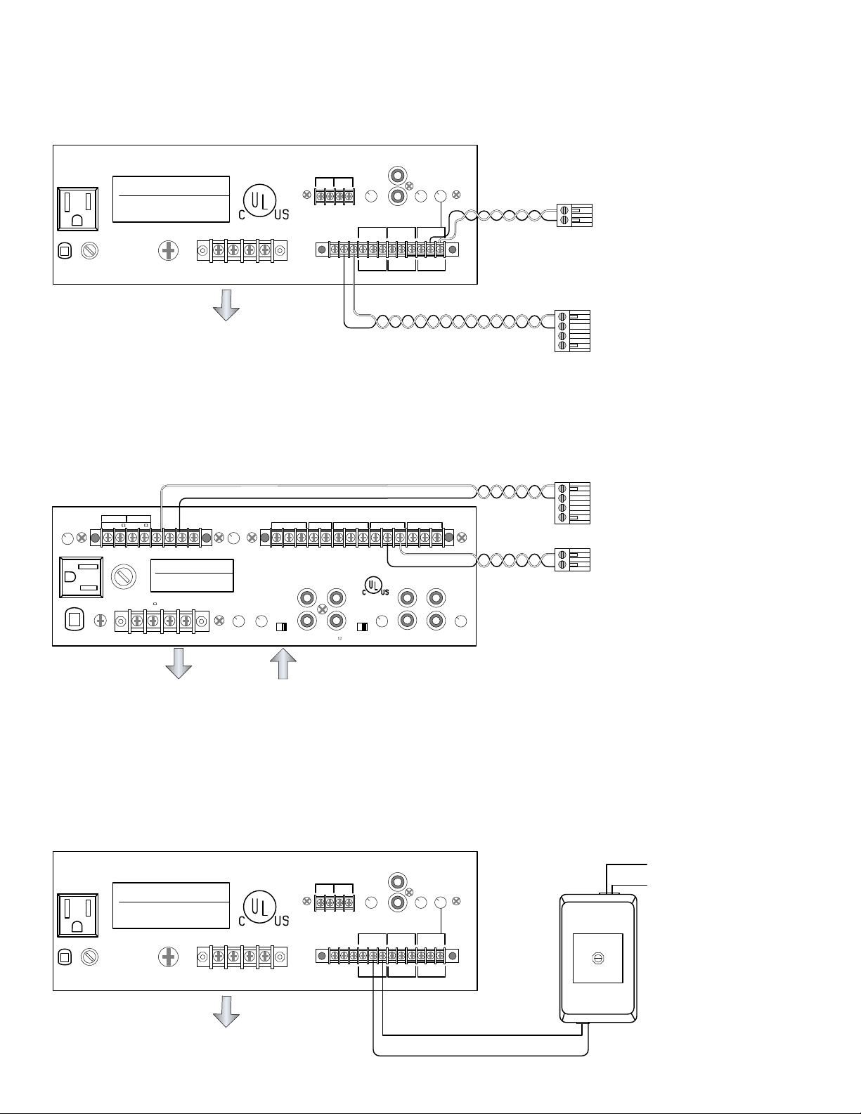
WIRING DIAGRAM
T3115BGM or T3130BGM with the AI-900AF:
Page through an overhead speaker system from an AI-900 system, using an AI-900AF card.
600 ohm
8 ohm
1 VOLT
1 WATT
117V~500W MAX
UNSWITCHED
paso
COM 8 25V 70V
AUX
47K ohm 100mv
IN PARALLEL
MOH
OUTPUT LEVEL
AUX
ATTENUATOR
600 ohm
250 ohm
10K ohm
1 mv
1 V
PROGRAM MIC TEL(PAGING)
TEL(PAGING)
OUTPUT LEVEL
100 mv
To CN4 on AI-900AF Card
To Tel (COM & HOT)
LINE FUSE
2A 250V
GROUND
UNMUTE G MUTE
Output to
Speaker System
WIRING DIAGRAM
DMA2060 or DMA2120 with the AI-900AF:
Page through an overhead speaker system from an AI-900 system, using an AI-900AF card.
INPUT 3
MOH
ZONE1
1 volt
MOH
LEVEL
2 watt max
0
0
600
24VDC
250ma
8
G
MUTE
UNMUTE
(-) (+)
ZONE 1
LEVEL
paso
GROUND
COM 8 25V 70V
VOX
SENS
AUX2
REMOTE
47k ohm
VOLUME
INPUT 4 (MIC-AUX2)
G COM HOT RVC RVC G COM HOT G COM HOT G COM HOT
PRE
OUT
MUTE
DELAY
3-60SEC
POWER
LINE OUT
IN
G COM HOT G COM HOT G COM HOT
BALANCED BALANCED BALANCED
To MUTE AND G
INPUT 3 (MIC) TEL (PAGING) INPUT 1 (MIC)
(AUX 1)
ATTNEUATOR
INPUT 3
47k ohm
MIX
BUSS
600
INPUT 4
47K ohm
L
(AUX 2)
ATTNEUATOR
R
To CN5 ~ CN8
on AI-900AF Card
(depending on programing)
To CN5 ~ CN8
on AI-900AF Card
(depending on programing)
To CN4 on AI-900AF Card
Output to
Speaker System
When not using “EQ LINK” ports,
adjust switch to “INTERNAL”
WIRING DIAGRAM
T3115BGM or T3130BGM with the BA-1 or BA-1P:
Page through an overhead speaker system from a channel selector on an Aiphone Master
Station. See page 1 for systems compatible with the BA-1 and BA-1P.
AUX
47K ohm 100mv
IN PARALLEL
600 ohm
8 ohm
MOH
1 WATT
OUTPUT LEVEL
10K ohm
1 V
PROGRAM MIC TEL(PAGING)
G COM HOT G COM HOT G COM HOT
BALANCED BALANCED BALANCED
250 ohm
Orange to PROGRAM “HOT”
Brown to PROGRAM “COM”
117V~500W MAX
UNSWITCHED
LINE FUSE
2A 250V
paso
COM 8 25V 70V
GROUND
Output to
Speaker System
1 VOLT
UNMUTE G MUTE
1 mv
AUX
ATTENUATOR
TEL(PAGING)
OUTPUT LEVEL
600 ohm
100 mv
TONE VOL
Yellow to # terminal on Master
Green to E on Master
BA-1
or
BA-1P
Page 3
Page 4

WIRING DIAGRAM
DMA2060 or DMA2120 with the BA-1 or BA-1P:
INPUT 3
MOH
ZONE1
1 volt
MOH
LEVEL
2 watt max
0
0
600
24VDC
250ma
8
G
MUTE
UNMUTE
(-) (+)
ZONE 1
LEVEL
paso
GROUND
COM 8 25V 70V
VOX
SENS
AUX2
REMOTE
47k ohm
INPUT 4 (MIC-AUX2)
G COM HOT RVC RVC G COM HOT G COM HOT G COM HOT
MUTE
DELAY
3-60SEC
EQLINK
INPUT 3 (MIC) TEL (PAGING) INPUT 1 (MIC)
VOLUME
PRE
MIX
OUT
BUSS
POWER
LINE OUT
IN
600
ATTNEUATOR
(AUX 1)
INPUT 3
47k ohm
INPUT 4
47K ohm
Orange to AUX2 “HOT”
Brown to AUX2 “COM”
L
(AUX 2)
ATTNEUATOR
R
BA-1 or BA-1P
TONE VOL
Output to
Speaker System
When not using “EQ LINK” ports,
adjust switch to “INTERNAL”
WIRING DIAGRAM
T3115BGM or T3130BGM with the MC-A/A on the MarketCom System:
AUX
47K ohm 100mv
IN PARALLEL
600 ohm
8 ohm
117V~500W MAX
UNSWITCHED
LINE FUSE
2A 250V
paso
GROUND
COM 8 25V 70V
1 VOLT
UNMUTE G MUTE
MOH
1 WATT
OUTPUT LEVEL
10K ohm
1 V
PROGRAM MIC TEL(PAGING)
G COM HOT G COM HOT G COM HOT
BALANCED BALANCED BALANCED
250 ohm
1 mv
AUX
ATTENUATOR
TEL(PAGING)
OUTPUT LEVEL
600 ohm
100 mv
1/+ 2 3 4 5/-
76
PROGRAM “HOT”
Output to
Speaker System
PROGRAM “COM”
WIRING DIAGRAM
DMA2060 or DMA2120 with the MC-A/A on the MarketCom System:
Yellow to # terminal on Master
Green to E on Master
To 24VDC + and 1 on MC-60/4
To 2 on MC-60/4
To 3 on MC-60/4
To 4 on MC-60/4
To 24VDC – and 5 on MC-60/4
MC-A/A
MA G
MOH
LEVEL
Page 4
MOH
ZONE1
2 watt max
1 volt
0
0
8
600
MUTE
paso
COM 8 25V 70V
GROUND
Output to
Speaker System
When not using “EQ
LINK” ports, adjust
switch to “INTERNAL”
INPUT 3
24VDC
250ma
G
UNMUTE
(-) (+)
ZONE 1
LEVEL
VOX
SENS
AUX2
REMOTE
47k ohm
INPUT 4 (MIC-AUX2)
G COM HOT RVC RVC G COM HOT G COM HOT G COM HOT
MUTE
DELAY
3-60SEC
EQLINK
INPUT 3 (MIC) TEL (PAGING) INPUT 1 (MIC)
VOLUME
PRE
MIX
OUT
BUSS
POWER
LINE OUT
IN
600
(AUX 1)
ATTNEUATOR
INPUT 3
47k ohm
INPUT 4
47K ohm
L
(AUX 2)
ATTNEUATOR
R
Adjust (AUX 2) attenuator accordingly
to obtain optimum output
To 24VDC + and #1 on MC-60/4
To #2 on MC-60/4
To #3 on MC-60/4
To #4 on MC-60/4
To 24VDC – and # 5 on MC-60/4
AUX2 “HOT”
AUX2 “COM”
1/+ 2 3 4 5/-
MA G
76
MC-A/A
Page 5

WIRING DIAGRAM
T3115BGM or T3130BGM with the PD-1 or PD-2 and TD-H System:
AUX
47K ohm 100mv
IN PARALLEL
600 ohm
8 ohm
117V~500W MAX
UNSWITCHED
LINE FUSE
2A 250V
paso
GROUND
COM 8 25V 70V
1 VOLT
UNMUTE G MUTE
MOH
1 WATT
OUTPUT LEVEL
10K ohm
1 V
PROGRAM MIC TEL(PAGING)
G COM HOT G COM HOT G COM HOT
BALANCED BALANCED BALANCED
TEL(PAGING)
OUTPUT LEVEL
AUX
ATTENUATOR
600 ohm
250 ohm
100 mv
1 mv
PROGRAM “HOT”
PROGRAM “COM”
C
+
DC12V -
To 12VDC + on TD-nH/B
To 12VDC – on TD-nH/B
To # on TD-nH/B
PD-1
MA G
AUX
47K ohm 100mv
IN PARALLEL
600 ohm
8 ohm
117V~500W MAX
UNSWITCHED
LINE FUSE
2A 250V
paso
GROUND
COM 8 25V 70V
1 VOLT
UNMUTE G MUTE
Output
used
determined
by speakers
MOH
1 WATT
OUTPUT LEVEL
10K ohm
1 V
PROGRAM MIC TEL(PAGING)
G COM HOT G COM HOT G COM HOT
BALANCED BALANCED BALANCED
TEL(PAGING)
OUTPUT LEVEL
AUX
ATTENUATOR
600 ohm
250 ohm
100 mv
1 mv
AUX2 INPUT 4 “HOT"
AUX2 INPUT 4 “COM"
WIRING DIAGRAM
DMA2060 or DMA2120 with the PD-1 or PD-2 and TD-H System:
INPUT 3
MOH
ZONE1
1 volt
MOH
LEVEL
2 watt max
0
0
600
24VDC
250ma
8
G
MUTE
UNMUTE
(-) (+)
ZONE 1
LEVEL
paso
GROUND
COM 8 25V 70V
VOX
SENS
AUX2
REMOTE
47k ohm
INPUT 4 (MIC-AUX2)
G COM HOT RVC RVC G COM HOT G COM HOT G COM HOT
MUTE
DELAY
3-60SEC
EQLINK
INPUT 3 (MIC) TEL (PAGING) INPUT 1 ( MIC)
VOLUME
PRE
MIX
OUT
BUSS
POWER
LINE OUT
IN
600
TONE
BYPASS
(AUX 1)
ATTNEUATOR
INPUT 3
47k ohm
INPUT 4
47K ohm
L
(AUX 2)
ATTNEUATOR
R
To 12VDC + on TD-nH/B
To 12VDC – on TD-nH/B
To # on TD-nH/B
To Talkback Paging Speakers
CSSVV
+
DC12V -
MA G
To 12VDC + on TD-nH/B
To 12VDC – on TD-nH/B
To # on TD-nH/B
C
+
DC12V -
MA G
PD-2
PD-1
Output to
Speaker System
MOH
GROUND
1 volt
0
600
MOH
LEVEL
ZONE1
2 watt max
0
8
MUTE
paso
COM 8 25V 70V
Output
used
determined
by speakers
“EQ LINK” ports,
24VDC
250ma
G
UNMUTE
(-) (+)
When not using
adjust switch to
“INTERNAL”
ZONE 1
LEVEL
When not using
“EQ LINK” ports,
adjust switch to
“INTERNAL”
INPUT 4 (MIC-AUX2)
G COM HOT RVC RVC G COM HOT G COM HOT G COM HOT
MUTE
VOX
DELAY
SENS
3-60SEC
EQLINK
AUX2
47k ohm
AUX2 INPUT 4 “HOT"
AUX2 INPUT 4 “COM"
INPUT 3
REMOTE
INPUT 3 (MIC) TEL (PAGING) INPUT 1 ( MIC)
VOLUME
PRE
MIX
OUT
BUSS
POWER
LINE OUT
IN
600
AUX2 INPUT 4 “HOT"
AUX2 INPUT 4 “COM"
TONE
BYPASS
(AUX 1)
ATTNEUATOR
INPUT 3
47k ohm
INPUT 4
47K ohm
L
(AUX 2)
ATTNEUATOR
R
To 12VDC + on TD-nH/B
To 12VDC – on TD-nH/B
To # on TD-nH/B
To Talkback Paging Speakers
CSSVV
+
DC12V -
MA G
PD-2
Page 5
Page 6

WIRING DIAGRAM
T3115BGM or T3130BGM with the YAW-R/B on the YAZ System:
AUX
47K ohm 100mv
IN PARALLEL
600 ohm
8 ohm
117V~500W MAX
UNSWITCHED
paso
COM 8 25V 70V
1 VOLT
MOH
1 WATT
OUTPUT LEVEL
10K ohm
1 V
PROGRAM MIC TEL(PAGING)
250 ohm
1 mv
AUX
ATTENUATOR
TEL(PAGING)
OUTPUT LEVEL
600 ohm
100 mv
LINE FUSE
2A 250V
GROUND
UNMUTE G MUTE
G COM HOT G COM HOT G COM HOT
BALANCED BALANCED BALANCED
PROGRAM “HOT”
PROGRAM “COM”
Output to
Speaker System
White wires to relay
(see YAW-R instructions)
WIRING DIAGRAM
DMA2060 or DMA2120 with the YAW-R/B on the YAZ System:
INPUT 3
MOH
ZONE1
1 volt
MOH
LEVEL
2 watt max
0
0
600
24VDC
250ma
8
G
MUTE
UNMUTE
(-) (+)
ZONE 1
LEVEL
paso
GROUND
COM 8 25V 70V
VOX
SENS
AUX2
REMOTE
47k ohm
INPUT 4 (MIC-AUX2)
G COM HOT RVC RVC G COM HOT G COM HOT G COM HOT
MUTE
DELAY
3-60SEC
EQLINK
INPUT 3 (MIC) TEL (PAGING) I NPUT 1 (MIC)
VOLUME
PRE
MIX
OUT
BUSS
POWER
LINE OUT
IN
600
(AUX 1)
ATTNEUATOR
INPUT 3
47k ohm
INPUT 4
47K ohm
L
(AUX 2)
ATTNEUATOR
R
MGA
4
321
5
-+6
GPTB
Not Used
To YAZ-90-W
Adjust (AUX 2) attenuator accordingly
to obtain optimum output
YAW-R
Page 6
Output to
Speaker System
When not using
“EQ LINK” ports,
adjust switch to
“INTERNAL”
(see YAW-R instructions)
AUX2 “HOT”
AUX2 “COM”
White wires to relay
MGA
4
321
YAW-R
5
-+6
To YAZ-90-W
GPTB
Not Used
Page 7

MODELS WATTAGE INPUTS OUTPUTS
T3115BGM 15 Watts Mic (250 ohm, 1 mV) 8 ohm
Telephone (600 ohm
Auxiliary (47K ohm
Program (10K ohm)
T3130BGM 30 Watts Mic (250 ohm, 1 mV) 8 ohm
Telephone (600 ohm
Auxiliary (47K ohm
Program (10K ohm)
DMA2060 60 Watts Mic (250 ohm, 1.5mV) 8 ohm
Telephone (600 ohm, 100mV) 25V
Input 3: Mic 3 - Aux 1 balanced 70V
Input 4: Mic 3 - Aux 2 balanced Zone 1 (8 ohm, 2W)
MOH (1V) Line out (600 ohm
DMA2120 120 Watts Mic (250ohm, 1.5mV) 8 ohm
Telephone (600ohm, 100mV) 25V
Input 3: Mic 3 - Aux 1 balanced 70V
Input 4: Mic 3 - Aux 2 balanced Zone 1 (8 ohm, 2W)
MOH (1V) Line out (600 ohm
1 mV) 25V
100mV) 70V
1 mV) 25V
100mV) 70V
See PASO Amplifier Installation Manual & Operating Instructions for complete information.
T3115BGM (15W); T3130BGM (30W)
DMA2060 (60W); DMA2120 (120W)
Page 7
Page 8

SERVICE ISSUES:
To receive Technical Support for connecting your Amplifier with an Aiphone system:
1. Contact Aiphone Technical Support at (800) 692-0200 during the hours of 6:00AM to 4:30 PM
Pacific Time.
2. For questions about the amplifier other than connection to the Aiphone system, contact Paso’s
Technical Support at (800) 231-3034.
To obtain Repair Service on your Paso Amplifier provided by Aiphone, please do the following:
1. Contact Aiphone Customer Service to receive a Repair Order Form, or locate it on our website
under Customer Service.
2. Fill out the form and email or fax it back to Aiphone to receive your RO number.
email: cust-serv@aiphone.com fax: 800-525-3372
3. We will provide you with the shipping information to return your amplifier for service.
See the back page of the Paso Amplifier instructions for further information on service issues.
IMPORTANT: If the Amplifier was Provided by Aiphone, you must contact Aiphone to get an
RO Number before sending your unit in for service.
SPECIFICATIONS and WARRANTY:
Refer to Paso Installation and Operating Instructions included with the Amplifier.
Aiphone Communication Systems
1700 130th Ave. N.E.
Bellevue, WA 98005
(425) 455-0510
FAX (425) 455-0071
TOLL FREE TECHNICAL SUPPORT:
(800) 692-0200
E-MAIL: tech-serv@aiphone.com
Aiphone-PASO Amp
Page 8
0407PHJS
 Loading...