

Page 1
Special
Order
Products
RY-PA-10/A
10 Relay Adaptor
For use with the LEF, LDF and NDR Systems
- INSTRUCTIONS -
The RY-PA-10/A is a multiple output relay adaptor, featuring 10 individually controlled relays with both
Normally Open and Normally Closed contacts. All relay contacts are rated at 240V AC, 300mA or 24V
DC, 1A. The RY-PA-10/A is ideal for systems providing selective door release, CCTV camera call-up, or
a combination of both.
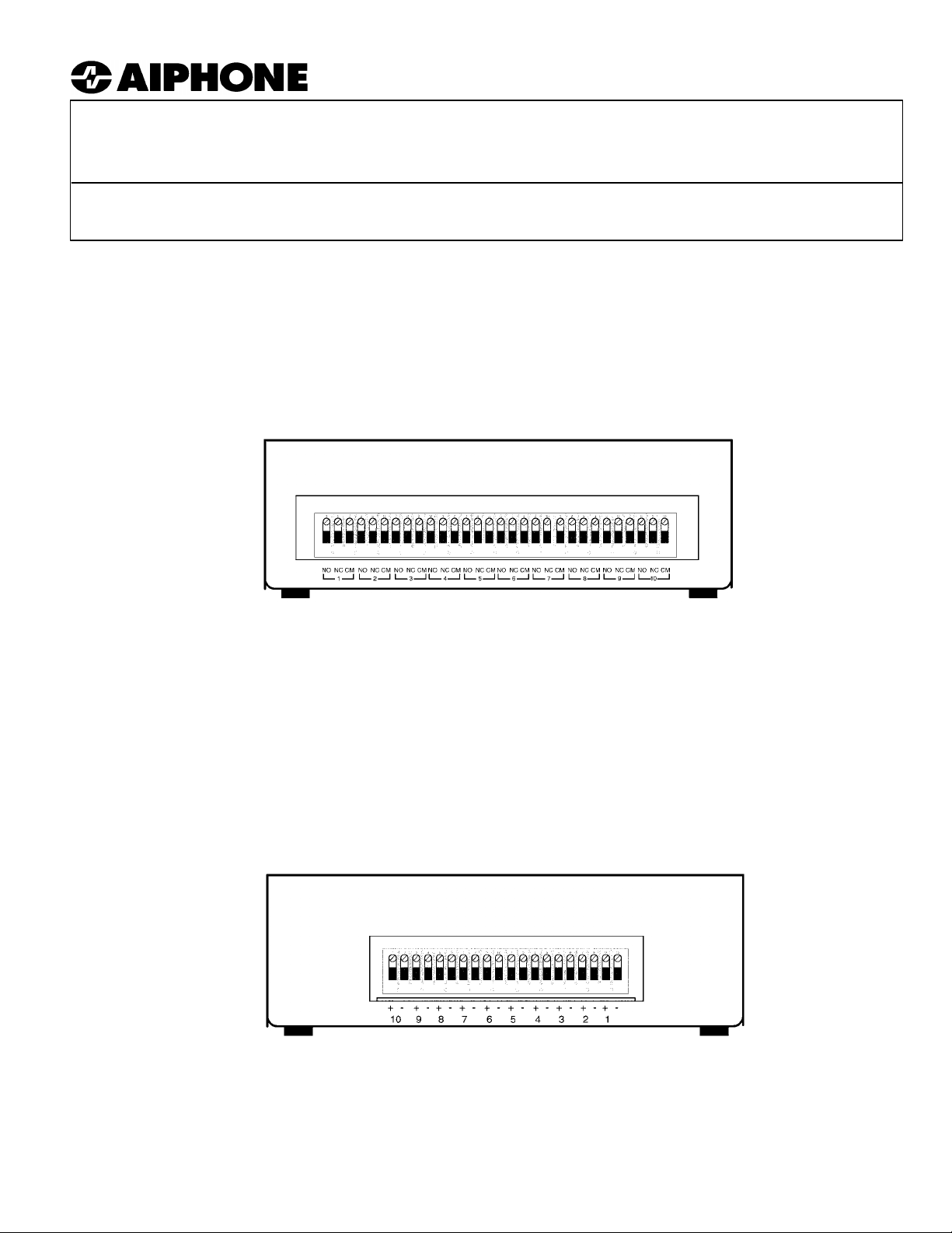
RY-PA-10/A Terminal Definition:
RY-PA-10/A Front View
(Output to devices)
NO1: Normally Open Contact, Relay #1
NC1: Normally Closed Contact, Relay #1
CM1: Common Contact, Relay #1
NO2: Normally Open Contact, Relay #2
NC2: Normally Closed Contact, Relay #2
CM2: Common Contact, Relay #2
NO3: Normally Open Contact, Relay #3
NC3: Normally Closed Contact, Relay #3
CM3: Common Contact, Relay #3
RY-PA-10/A Back View
(Input from intercom)
NO4: Normally Open Contact, Relay #4
NC4: Normally Closed Contact, Relay #4
CM4: Common Contact, Relay #4
NO5: Normally Open Contact, Relay #5
NC5: Normally Closed Contact, Relay #5
CM5: Common Contact, Relay #5
NO6: Normally Open Contact, Relay #6
NC6: Normally Closed Contact, Relay #6
CM6: Common Contact, Relay #6
1+: Positive 12V DC Input, Relay #1
1-: Negative, Relay #1
2+: Positive 12V DC Input, Relay #2
2-: Negative, Relay #2
3+: Positive 12V DC Input, Relay #3
3-: Negative, Relay #3
4+: Positive 12V DC Input, Relay #4
4-: Negative, Relay #4
5+: Positive 12V DC Input, Relay #5
5-: Negative, Relay #5
NO7: Normally Open Contact, Relay #7
NC7: Normally Closed Contact, Relay #7
CM7: Common Contact, Relay #7
NO8: Normally Open Contact, Relay #8
NC8: Normally Closed Contact, Relay #8
CM8: Common Contact, Relay #8
NO9: Normally Open Contact, Relay #9
NC9: Normally Closed Contact, Relay #9
CM9: Common Contact, Relay #9
NO10: Normally Open Contact, Relay #10
NC10: Normally Closed Contact, Relay #10
CM10: Common Contact, Relay #10
6+: Positive 12V DC Input, Relay #6
6-: Negative, Relay #6
7+: Positive 12V DC Input, Relay #7
7-: Negative, Relay #7
8+: Positive 12V DC Input, Relay #8
8-: Negative, Relay #8
9+: Positive 12V DC Input, Relay #9
9-: Negative, Relay #9
10+: Positive 12V DC Input, Relay #10
10-: Negative, Relay #10
Pg. 1
Page 2
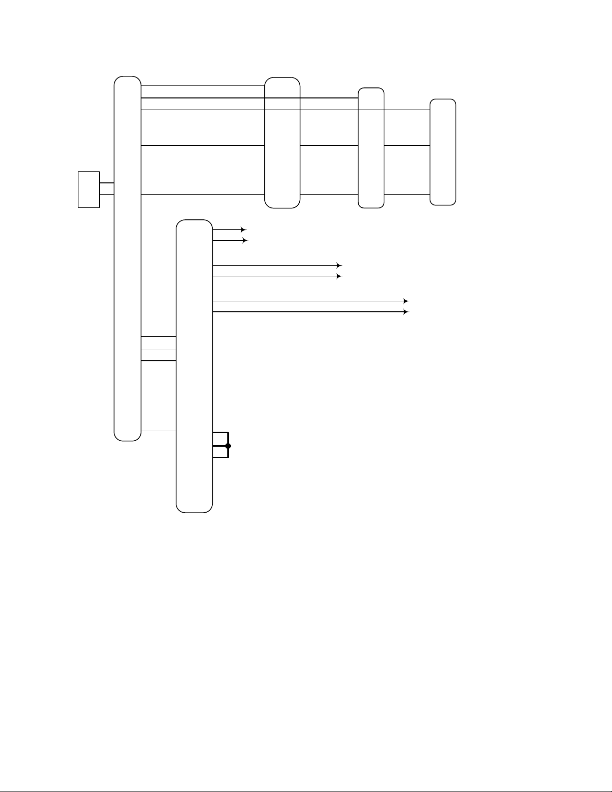
WIRING DIAGRAM: RY-PA-10/A USED FOR SELECTIVE DOOR RELEASE
PS-1225UL
+
-
LEF-10
1
2
3
~
10
E
R
Y
+
-
K1
K2
K3
~
K10
L
RY-PA-10/A
CM1
NO1
CM2
NO2
CM3
NO3
12345-
~
10-
1+
2+
3+
4+
5+
~
10+
LS-NVP/B
Red
Blk
Grn
To Door
Release #1
Notes:
1. Tie all the #+'s together of the relays that will be
used for door release activation.
2. The "L" terminal provides +12V DC when door
release button is pressed.
3. Normally Open contacts will be closed as long as
the door release button is pressed.
4. Only wiring concerning door release is shown
here. For complete system information, refer to
the system installation manual.
LE-D
1
E
-
To Door
Release #2
LE-DA
1
E
-
To Door
Release #3
Pg. 2
Page 3

WIRING DIAGRAM: RY-PA-10/A USED FOR CCTV CAMERA CALL-UP
PS-2420UL
+
-
External
Terminal Block
NDR-20A
1
2
3
~
20
E
+
-
1
2
3
~
20
L
RY-PA-10/A
CM1
NO1
CM2
NO2
CM3
NO3
12345-
~
10-
Leave green
jumper intact
NE-NVP
Red
Blk
Grn
Grn
NA-NE
Red
Blk
Grn
Maintained Closure
for Stn. #1
Maintained Closure
for Stn. #2
NE-DA
1
2
Blk
Wht
Maintained Closure
for Stn. #3
H
1+
2+
3+
4+
5+
~
10+
Notes:
1. Tie all the #+'s together of the relays that will be
used for CCTV camera call-up.
2. The "H" terminal from the NDR master provides
+12V DC when a sub station is selected.
3. Normally Open contacts will be closed as long as
master has sub station selected.
4. Only wiring concerning door release is shown
here. For complete system information refer to the
system installation manual.
Pg. 3
Page 4

WIRING DIAGRAM: RY-PA-10/A USED FOR BOTH SELECTIVE DOOR RELEASE
AND CCTV CAMERA CALL-UP
PS-2420UL
+
-
External
Terminal Block
NDR-20A
1
2
3
~
20
E
+
-
H
1
2
3
~
20
L
RY-PA-10/A
CM1
NO1
CM2
NO2
CM3
NO3
CM4
NO4
CM5
NO5
CM6
NO6
123456-
~
10-
1+
3+
5+
2+
4+
6+
~
10+
Leave green
jumper intact
NE-NVP
Red
NA-NE
Red
NE-DA
1
Blk
Grn
Grn
Blk
Grn
2
Blk
Wht
Door Release for Stn. #1
Maintained Closure for Stn. #1
Door Release for Stn. #2
Maintained Closure for Stn. #2
Door Release for Stn. #3
Maintained Closure for Stn. #3
Notes:
1. Use diodes of a value between 1N4001 ~ 1N4007
or equivalent.
2. Tie all the #+'s together of the relays that will be
used for CCTV camera call-up.
3.Tie all the #+'s together of the relays that will be
used for door release activation.
4. Normally Open contacts tied to the "H" terminal
will be closed as long as master has sub station
selected.
5. Normally Open contacts tied to the "L" terminal on
the separate terminal block will be closed as long
as the door release button is pressed.
6. Only wiring concerning relay connection is shown
here. For complete system information refer to the
system installation manual.
Aiphone Communication Systems
1700 130th Ave. N.E.
Bellevue, WA 98005
(425) 455-0510
FAX (425) 455-0071
TOLL FREE TECHNICAL SUPPORT:
(800) 692-0200
TOLL FREE FAX LINE:
(800) 832-3765
E-MAIL: tech-serv@aiphone.com
RY-PA-10/A Instr.
Pg. 4
1103bkjs
 Loading...