

Page 1
RY-IP44
Input/Output Network Adaptor
Programming Manual
For use with IX Series, IS-IP Series, and IPW-1A
1214
ATTENTION:
This is the programming manual for the RY-IP44 only. Refer to the Installation and Setting
Manuals for the series being integrated with for complete installation/programming information
on each system (IX, IS-IP, IPW-1A).
Page 2

Package Contents
Installation Requirements
• RY-IP44
• Programming Manual
• Barix Quick Install Guide
• General understanding of IX Series, IS-IP Series,
or IPW-1A programming
• 9-30V DC power supply (sold separately)
• Unique IP address for each adaptor
Overview / Description
The RY-IP44 is an IP adaptor with 4 relay outputs and 4 contact inputs. This adaptor is designed to work
with Aiphone’s IX Series, IS-IP Series, and IPW-1A network intercom systems.
Relay outputs on the RY-IP44 can be programmed to trigger when a station is calling, while in
communication, or while calling and communicating. Relay outputs can also be programmed for door
release. The RY-IP44 relays can be used in place of a station’s built-in relay.
When using with the IX Series, relay outputs on the RY-IP44 can be associated to any station. When using
with the IS-IP Series or IPW-1A, relay outputs can only be associated to door stations.
Inputs on this adaptor are used to trigger a call and can only be used on the IX Series and IS-IP Series.
When using with the IX Series, inputs can be programmed to call from any station to any other station.
When using with the IS-IP Series, inputs can be programmed to call from a door station to a master station.
Possible applications are notication of a card access denial, motion detector activation, or selective calling
(i.e. multiple tenants). For multiple tenant applications, Aiphone recommends using the IS-IP4DVF 4-button
selective call video door station.
The RY-IP44 adaptor is not a PoE device. A dedicated 9-30V DC power supply is required. Use the Aiphone
PS-1225UL power supply (sold separately).
SIF.ini File (IX Series and IS-IP Series Only)
Note:
The intercom system must be fully programmed and operational prior to programming the RY-IP44 adaptor.
A SIF.ini le must be created in order for the IX Series and IS-IP Series door stations and master stations to
communicate with the adaptor. Use a text editor program to create this le and save it with a .ini extension.
Example Text File:
0100,192.168.1.45,10000,0
0101,192.168.1.46,10001,0
Each line in the text le
represents a different
}
RY-IP44 adaptor.
0110,192.168.1.47,10002,0
Program
Type
Program Type: Range is between 0100 and 1111 (Binary). Set a different program type for each
RY-IP44 being programmed.
Destination IP Address:
Destination Port:
the range from 1 to 65535.
SSL Y/N :
Once the le is created, save it to a location on the PC being used for programming the IX Series or IS-IP
Series stations. This le will need to be uploaded to each device that will be associated with the RY-IP44 using
the instructions that follow.
IP address assigned to the RY-IP44.
Port number assigned on the RY-IP44. The default port is 10000. This can be set in
This device does not use SSL. Input 0 for no.
Destination
IP Address
Destination
Port
SSL
Y/N
2 | RY-IP44 Programming Manual
Page 3
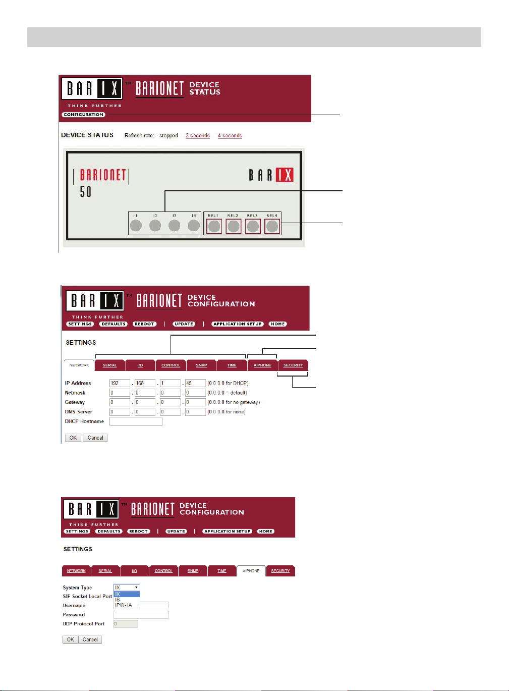
Conguring the RY-IP44 (assigning IP address and system use)
The RY-IP44 has a default IP address of 192.168.1.45. Open a web browser and point the address bar to
http://192.168.1.45 for access to the adaptor. The rst screen to appear will be the Device Status screen.
Conguration button
Digital input status
Relay status and control.
Click on each LED to
verify relay function.
Click the CONFIGURATION button to open the Device Conguration screen. This is where a unique IP Address,
Netmask, and Gateway can be assigned to the adaptor. Consult with your IT department for these settings.
Settings not utilized for Aiphone
functionality. Do not adjust.
AIPHONE: Select the Aiphone system
type the relay is to be used with.
SECURITY: For creating a password for
access to the web browser interface.
Click the AIPHONE tab. From this screen, the Aiphone system type that the relay is being integrated with will be
selected. Use the drop down by System Type to select the appropriate system. Once selected, click OK. Click
Reboot on the next screen to restart the adaptor.
System Type: Choose between IX, IS, & IPW-1A
SIF Socket Local Port: Enter the port number
that was assigned in the SIF.ini le. Leave at “0”
to use default 10000 port.
Username & Password: For IX/IS, enter
system’s username and password. Leave blank if
using default (IX = admin, IS = aiphone).
UDP Protocol Port: Used for IPW-1A only. Enter
“0” if default port (1724) is to be used.
3
Page 4
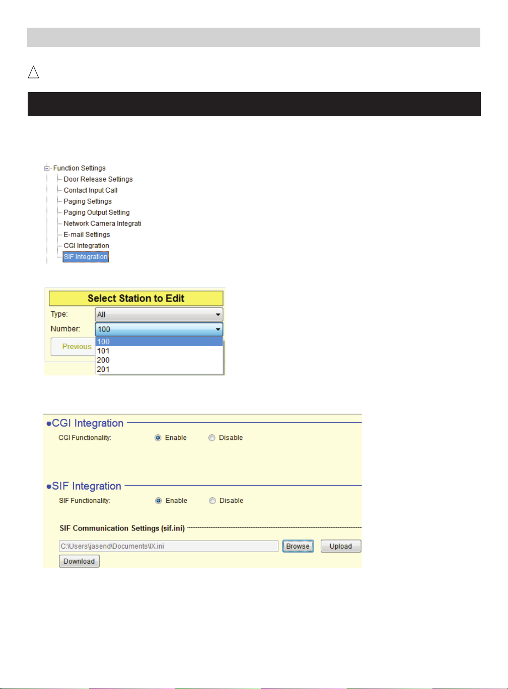
IX Series: Uploading SIF.ini File
The SIF.ini le must be uploaded to each IX station associated with the RY-IP44 adaptor.
! The IX Support Tool or web browser interface can be used to upload the SIF.ini le to each station.
Loading via the IX Support Tool is shown in these instructions.
Note:
The intercom system must be fully programmed and operational prior to uploading the SIF.ini le.
A. Log in to the IX system using the IX Support Tool.
B. Expand the Function Settings tree on the left and select SIF Integration.
Select the station to be edited from the Number drop down menu.
C.
D. Select the Enable radio button for both the CGI Integration and SIF Integration.
Click Browse to browse to where the .ini le is saved and click Upload to send to station.
E. Click Update to save the changes for the station then repeat the process for each station that will be
associated with the RY-IP44.
F. After uploading the .ini le and updating each station, upload the settings to each station. Click File,
Uploading Settings to Station. Select the stations to upload to and click Start Upload.
4 | RY-IP44 Programming Manual
Page 5

IX Series: Relay Output Programming
The RY-IP44 has 4 relays. These relays can be programmed to trigger while calling, while in communication, or
while calling and communicating with a specic door station. The relays can also be programmed for door release.
Set the RY-IP44 for use with the IX Series (refer to page 3).
From the Device Conguration screen, click APPLICATION SETUP.
APPLICATION SETUP button
Relay Action options:
• Door Release - Normally-Open
• Door Release - Normally-Closed
• Active while Calling from source
• Active while in Communication with source
• Active during Calling and Communication
The IX Series allows for door release partitioning. When the RY-IP44 relay action is set for door release, the
relay will be triggered only if door release is allowed on the station. To set door release partitioning, refer to
Door Release Settings under the Function Settings tree in the IX Support Tool.
Relay will trigger when the associated station’s door release
}
contact is triggered.
Relay will trigger when the associated station calls or
}
communicates.
When the relay action is set for the “Door Release” options, the relay on the RY-IP44 will trigger when the
associated station is calling or communicating and its door release contact is triggered.
When the relay action is set for any of the “Active While” options, the relay will trigger when the associated
station calls or communicates at any priority level.
Enter the station number of the station to be associated with the relay. Select the relay condition from the
Relay Action drop down menu.
Click on Apply Settings then click Reboot to restart the adaptor with the saved changes.
When the entered station is active, the associated relay will trigger based on the Relay Action settings.
5
Page 6

IX Series: Input Programming
The RY-IP44 adaptor has 4 inputs. These inputs can be programmed to trigger a call-in from a specic door station
or master station to a specic master station or group of master stations.
The RY-IP44 inputs can have different calling rules than the default calling rule set during the IX Series programming.
Select the call-in priority level for each input using the Priority drop down menu.
Enter the target IP address of the station for remote call-in.
Click Apply Settings to save the changes. Do not reboot the adaptor at this time.
Click APPLICATION SETUP to return to the Application Conguration Screen.
Click on Destinations next to the input being congured. Another window will open. Enter the station number
of the master(s) that will need to be called when the input is triggered.
When the target IP address is a door station, a maximum of 20 masters can be entered.
When the target IP address is a master station, a maximum of 20 masters or 1 group can be entered. A group
can consist of up to 50 masters and must be created using the IX Support Tool.
Check the Enable box beside each station entered.
Click on Apply Settings then click Reboot to restart the adaptor with the changes.
6 | RY-IP44 Programming Manual
Page 7

IS-IP Series: Uploading SIF.ini File
The SIF.ini text le must be uploaded to each IS-IP device associated with the RY-IP44 adaptor.
! Note that the IP address for each IS-IP unit will be unique for your network settings.
Note:
The intercom system must be fully programmed and operational prior to uploading the SIF.ini le.
A. Open a web browser and type https://[ip address]/sif in the address bar.
[ip address] = static IP address assigned to the IS-IP station being programmed.
B. A security certicate error message will appear. Continue to the website.
C. Enter the administrator ID and password.
Default ID: aiphone
Default Password: aiphone
Select Transmission setting under “Uploading SIF setting data” from the menu on the left side of the screen.
D.
E. Click the Upload button. A new window will open.
F. Click the Browse button and navigate to the .ini le saved on the PC.
G. Click the Upload button. A message will appear stating the settings will not be applied until the system is
updated.
H. Click Updating the system from the menu on the left. Click the Update button and the unit will update
and restart itself.
I. Repeat this process for each IS-IP door and master station to be associated with the RY-IP44 adaptor.
7
Page 8

IS-IP Series: Relay Output Programming
The RY-IP44 has 4 relays. These relays can be programmed to trigger when a specic door station is calling,
while in communication, or while calling and communicating. The relays can also be programmed for door
release from one or multiple IP master station(s).
Set the RY-IP44 for use with the IS-IP Series (refer to page 3).
From the Device Conguration screen, click APPLICATION SETUP.
Application Setup button
Linked Stations Table:
Enter the IP address and TermID for each IS-IP station in the IS conguration. This table is used as a
reference for each TermID in the system. After inputting each IP address and TermID, click Apply Settings
at the bottom of the page to save the settings to memory. Return to the Application Screen or reboot adaptor
by clicking the Reboot button. Rebooting must occur to update adaptor settings.
Denition: TermID
A TermID identies the location of an IS-IP device in the IS Series conguration. It also distinguishes
between master station units and door station units. A master station TermID will be xx-001 and a
door station TermID will be xx-101. “xx” represents the line in which the station resides under “IP Unit
Registration” in the IS Host programming.
Example:
01-101: Door station in address location 1.
03-001: Master station in address location 3.
8 | RY-IP44 Programming Manual
Page 9

IS-IP Series: Relay Output Programming (cont.)
Relay Functionality:
Enter the TermID for the door station to be associated to the relay (see page 8 for TermID denition).
Select the relay action from the drop down menu.
Relay Action options:
• Door Release - Normally-Open
• Door Release - Normally-Closed
• Active while Calling from source
• Active while in Communication with source
• Active during Calling and Communication
When the relay actions are set for the “Door Release” options, the relay will trigger when the associated door
station is in communication, but only when a “congured” master station pushes the door release button.
When the relay actions are set for any of the “Active While” options, the relay will trigger when the
associated door station calls or communicates at any priority level.
After the Door TermID and Relay Action has been set, click Apply Settings at the bottom of the screen to
save the settings to memory. Return to the Application Screen or reboot adaptor by clicking on the Reboot
button. Rebooting must occur to update adaptor settings.
Relay will trigger when a congured master station pushes the
}
door release button for the associated door.
Relay will trigger when the associated door station
}
calls or communicates.
To program a master station to control door release, click on the Congure button. A new window will open
and the table shown below will be populated based on the entries made in the Linked Stations Table (see
page 8). Check the Flag box beside each master station that will be “allowed” to trigger this relay for door
release. Once all masters have been checked, click Apply Settings at the bottom of this window to save
the settings to memory. Reboot to update adaptor settings.
Note: The IS-SOFT software masters can NOT be enabled for door release using the RY-IP44.
9
Page 10

IS-IP Series: Input Programming
The RY-IP44 adaptor has 4 inputs. These inputs can be programmed to trigger a call-in from a specic door
station to a specic master station or group of master stations (max. 20). The RY-IP44 inputs can have different
calling rules than the default calling rule set under Advanced Station Settings in the IS Host Programming.
Choose the Call-In priority level for each input using the Priority drop down menu. Enter the target IP
address of the door station for remote call-in.
Click Apply Settings to save the changes. Do not reboot the adaptor at this time.
Click APPLICATION SETUP to return to the Application Conguration screen.
Click on Destinations next to the input being congured. A new window will open. Enter the TermID for
each master station to be called (see page 8 for TermID information). A maximum of 20 master TermID’s
can be entered. Check the Enable box beside each TermID entered to allow the master to be called. Once
all master station TermID’s have been entered and enabled, click Apply Settings at the bottom of this
window to save the settings to memory. Reboot to update adaptor settings.
10 | RY-IP44 Programming Manual
Page 11

IPW-1A: Relay Output Programming
The RY-IP44 has 4 relays. These relays can be programmed to trigger while calling, while in communication, or
while calling and communicating with a specic door station. The relays can also be programmed for door release.
Set the RY-IP44 for use with the IPW-1A (refer to page 3).
Relay Action options:
• Door Release - Normally-Open
• Door Release - Normally-Closed
• Active while Calling from source
• Active while in Communication with source
• Active during Calling and Communication
ctive While Any Station Calling
• A
* When using the RY-IP44 for door release, the relay on the IPW-1A must be set to door release and the relay
must be jumpered to the sensor input as shown below.
*Relay will trigger when the PC master station pushes the door
}
release button.
Relay will trigger when the associated door station
}
calls or communicates.
}
Relay triggers when any station calls. No assignment required.
IN0 IN1 NO C NC
From the Device Conguration screen, click APPLICATION SETUP.
Application Setup button
Enter the Station ID for the IPW-1A to be associated with each relay on the RY-IP44. Select the relay
condition from the Relay Action drop down menu. When done, click on Apply Settings. Click Reboot on the
next screen to restart the adaptor with the applied settings.
11
Page 12

RY-IP44 Dimensions
EL-12S
1-1/8"
PT
PT
PT
Mounting:
3-5/16”
Depth:
1-1/4”
4-1/8”
The RY-IP44 adaptor mounts to an Aiphone
W-DIN11 mounting rail (sold separately).
RY-IP44 Wiring
=
Power Transformer (use proper power for the strike, mag lock, or external signaling device being used).
Relay contact rating: 30V DC, 0.5A.
Door release: External signaling:
Relay 1
Relay 2
Relay 3
Relay 4
R1
{
NO
R2
{
NO
R3
{
NO
R4
{
NO
Door
Strike
Inputs:
Connect a normally open (N/O) button across any
input and ground.
Relay 1
Relay 2
Relay 3
Relay 4
Power:
Use a 9-30V DC (300mA @ 12VDC) power supply to
power the RY-IP44 adaptor.
R1
{
NO
R2
{
NO
R3
{
NO
R4
{
NO
Bell
Use the Aiphone
PS-1225UL power supply (sold separately).
Input 1
Input 2
Input 3
Input 4
Ground
FCC WARNING:
This device complies with Part 15 of the FCC rules.
Operation is subject to the following two conditions:
(1) This device may not cause harmful interference.
(2) This device must accept any interference that may cause undesired operation.
• For proper regulatory compliance, the drain wire should be disconnected at the power supply end of the cable.
• Changes or modications not expressly approved by the party responsible for compliance could void the user’s
I1
I2
I3
I4
G
{
G
authority to operate the equipment.
Power
PS-1225UL
+
{
-
+
-
1214
12 | RY-IP44 Programming Manual
1700 130th Ave. NE Bellevue, WA 98005
Aiphone Corporation
Ph: (800) 692-0200 Fax: (425) 455-0071
www.aiphone.com tech@aiphone.com
 Loading...