

Page 1
0415
RY-ES
External Signaling Relay
- INSTALLATION & OPERATION INSTRUCTIONS -
The RY-ES is a relay used to activate an external signaling device when the door station calls in. It can be
used for call extension on the JP, JO, JK, JF, KB, AX, NEM, DB, and IE systems (excluding IE-8MD). The
relay connects to the chime output of the master station in place of the IER-2. The RY-ES relay shares power
with the master station it is connected to.
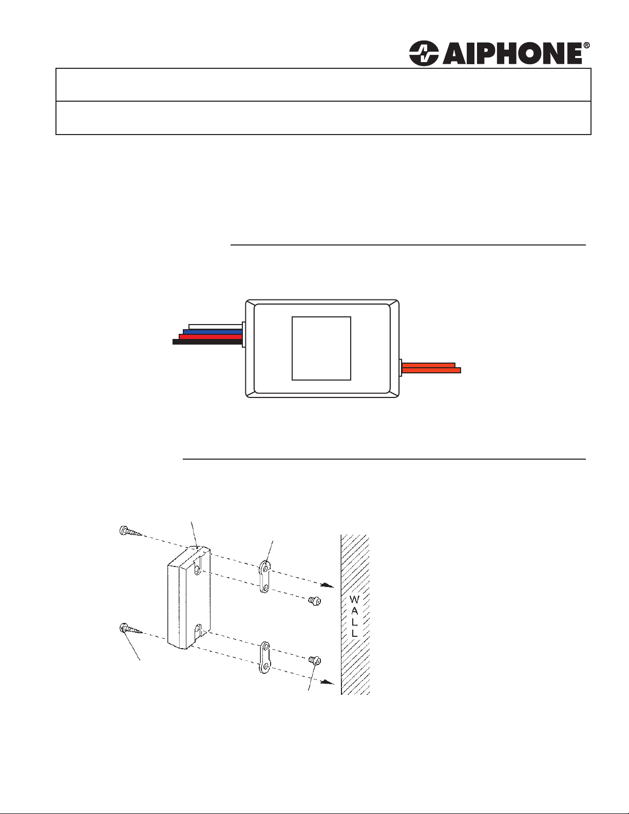
1 NAMES & FUNCTIONS
Input of relay:
Red: Positive Power
Black: Negative Power
White: Activation wire
Blue: Activation wire
RY-ES
Output of relay:
2 Orange wires
N/O Dry contact closure
2 INSTALLATION
Wood screw (2)
RY-ES
Mounting
bracket (2)
Screw (2)
Wall mount the unit with the
supplied mounting hardware as
shown in the diagram to the left.
When making wire connections,
be sure not to short any wires
together. Use wire nuts or
another protective material to
isolate the connections.
RY-ES Instructions
Pg. 1
Page 2
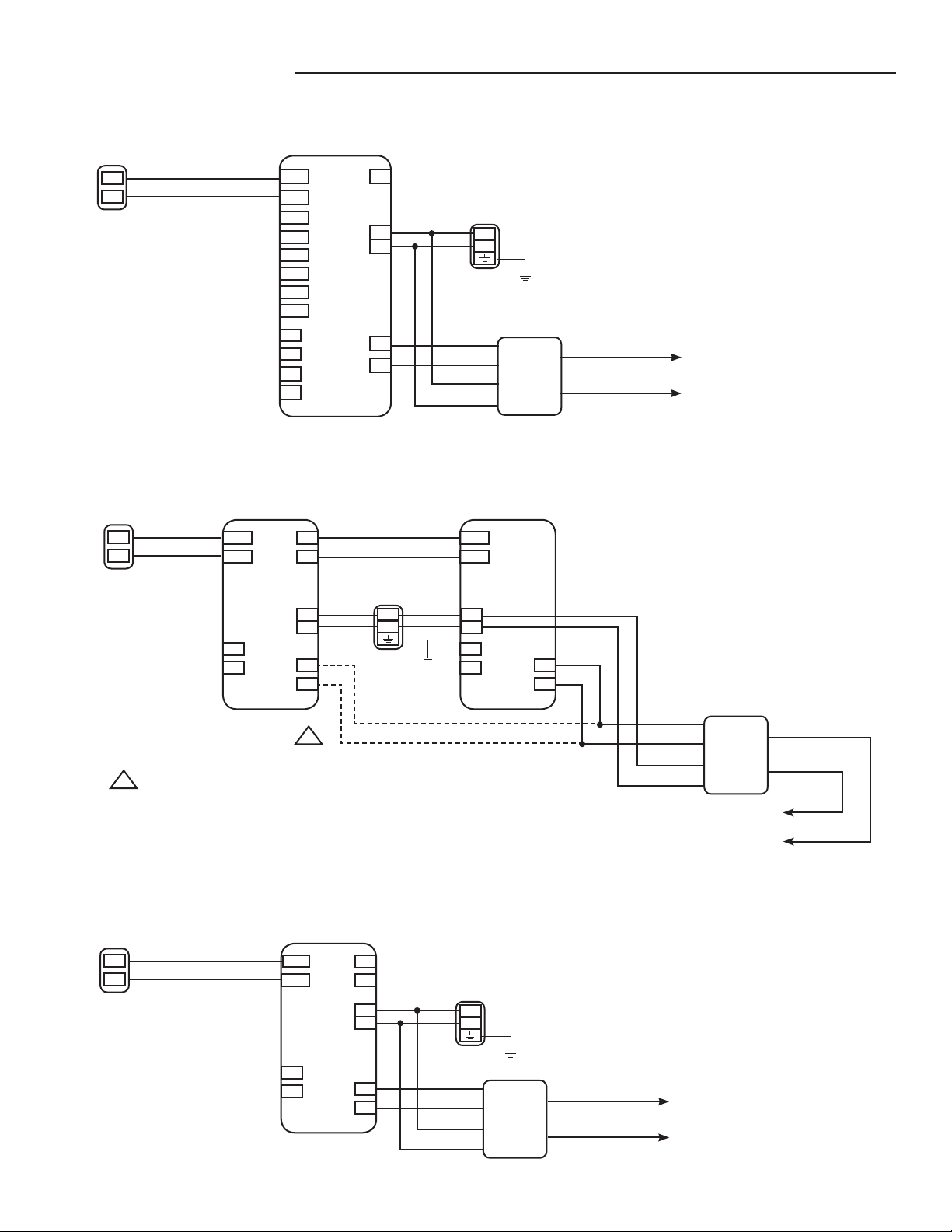
3 WIRING DIAGRAMS
JP System
Door
A1
A2
JO System
Door
A1
A2
Connect the RY-ES relay to either the JO-1MD master station or
!
the JO-1FD expansion station. Do not connect the same relay to
both stations.
JP-4MED
1A1
1A2
2A1
2A2
3A1
3A2
4A1
4A2
L1
L1
L2
L2
JO-1FD
Expansion Station
A1
A2
L
L
DOOR
B1
B2
MASTER
STATION
+
-
S
S
CALL EXT
!
M(OUT)
+
-
S
S
CALL EXT
PS-1820UL
+
-
PS-2420UL
+
-
Blue
White
Red
Black
RY-ES
JO-1MD
Master Station
A1
A2
DOOR
+
-
L
L
CALL EXT
S
S
Orange
External Device
and Power
Blue
White
Red
Black
RY-ES
External Device
and Power
Orange
JK & JF Systems
Door
A1
A2
RY-ES Instructions
Pg. 2
JK-1MD/JK-1MED, JF-2MED
A1
A2
L
L
DOOR
B1
B2
SUB OUTCALL EXT
+
-
S
S
PS-1820UL
+
-
Blue
White
Red
Black
RY-ES
Orange
External Device
and Power
Page 3

3 WIRING DIAGRAMS (cont)
KB System
KB-3MRD
Door
A1
A2
1A1
1A2
B1
B2
+
-
PS-2420UL
+
-
AX System
AX-DV
AX-8M/AX-8MV
Cat5e
S
S
Cat5e
Blue
White
Red
Black
RY-ES
Orange
External Device
and Power
PS-2420UL
-
+
Black
Red
White
Blue
RY-ES
Orange
PS-2420UL
-
+
External Device
and Power
RY-ES Instructions
Pg. 3
Page 4

3 WIRING DIAGRAMS (cont)
NEM System
NA-A
A
B
C
D/E
+
-
PS-2420UL
NEM-10/C
1
~
10
E
S
+
-
IMPORTANT:
The NEM call tone volume levels (front and back) must be
set to medium or high in order for the RY-ES to trigger.
White
Blue
Red
Black
RY-ES
Orange
External Device
and Power
DB System
DA-1DS
D
E
L
L
DB-1MD
D
E
B1
B2
B3
B4
BL+
BL-
15V
~ ~
~ ~
PT-1211C
Org
Yel
White
Blue
Red
Black
External Device
and Power
RY-ES
Orange
IE System
IE Door IE-1GD / IE-2AD
1
2
~
~
PT-1210N
The RY-ES will work with the IE-1GD, IE-2AD, and IE-1AD.
Connections for the IE-1GD and IE-2AD are shown above.
When using the IE-1AD, connect the white/blue wires of the
RY-ES to the white leads of handset.
The RY-ES is NOT compatible with the IE-8MD.
D1
E1
(D2)
(E2)
T
R
C
E
+
-
White
Blue
Red
Black
External Device
and Power
RY-ES
Orange
4 SPECIFICATIONS
Power Source: 12-30V DC, 12-16V AC. Power supplied by master.
Current consumption: DC: Standby 10mA. Max 60mA
AC: Standby 15mA. Max 70mA
Contact rating: 125V AC 1.0A
30V DC 1.0A
Aiphone Communication Systems
1700 130th AVE N.E.
Bellevue, WA 98005
(425) 455-0510
FAX (425) 455-0071
Toll Free Technical Support:
1-800-692-0200
E-mail tech@aiphone.com
RY-ES Instructions
Pg. 4
0415JD
 Loading...