

Page 1

RY-1824L
19310 0519
RY-1824L
Form C Door Release Relay for AX, KB, JF, JO, and JP Series
- INSTRUCTIONS -
The RY-1824L door release relay module is an interface between the door release contact on the Aiphone master station
or CEU and the actual release mechanism. The contact closure directly from the master station or CEU has limited voltage
and current capacity. Use the RY-1824L to ensure that the contact rating will be sufficient for the electric strike or magnetic
lock used. The relay’s contact rating supports a majority of door release hardware available. This relay is recommended
for all AX, KB, JF, JO, and JP Series systems when using door release and will protect the built-in contact from possible
surge damage.
(Note: Use the RY-3DL when releasing more than two doors in a JP Series, or more than one door in a JF or KB Series).
INSTALLATION:
1. Install near the power source for the door release mechanism, or behind the master station or CEU.
2. Secure wire connections with proper termination, such as wire nuts or crimp connectors.
3. Trim the wires to the desired length.
4. Trim the unused contact wire so the bare strands are not exposed.
WIRING DIAGRAMS:
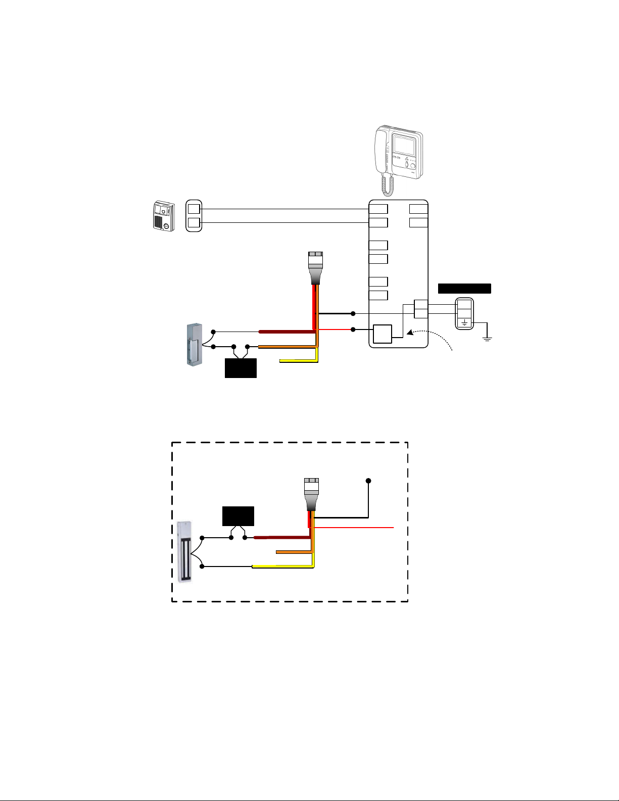
JP Series Wiring
RED: (+) Pos.
BLK: (-) Neg.
BRN: Common
ORG: N/O
YEL: N/C
RY-1824L COLOR CODE:
Input of Relay:
Red: (+) Positive
Black: (-) Negative
Output of Relay:
Brown: Common
Orange: N/O contact
Yellow: N/C contact
(See contact rating specs on page 4)
ELECTRIC STRIKE
WIRING METHOD:
(Normally Open contact)
MAGNETIC LOCK
WIRING METHOD:
(Normally Closed contact)
Door
Release
Door
Release
#2
#1
Door #2
JP-DV
Door #1
JP-DV
LOCK
POWER
A1
A2
RY-1824L
Brn
Org
Yel
A1
A2
RY-1824L
Brn
Org
Yel
Blk
Red
COM
N/O
N/C
Blk
Red
JP-4MED
1A1
M(Out)
1A2
DOOR 1DOOR 2
2A1
2A2
3A1
3A2
DOOR 3DOOR 4
4A1
4A2
L1
L1
L2
L2
+
-
PS-2420UL
+
-
LOCK
POWER
NOTE: The door release contacts on the station are rated at 24V AC/DC, 500mA. The RY-1824L should be used in any
application where the strike or maglock has a higher voltage or draws more current. Otherwise, internal damage to the
master station could occur.
Page 1
Page 2
WIRING DIAGRAMS (cont):
KB Series Wiring
KB-3MRD
KB-DAR
A1
A2
ELECTRIC STRIKE
WIRING METHOD:
(Normally Open contact)
LOCK
POWER
MAGNETIC LOCK
WIRING METHOD:
(Normally Closed contact)
RY-1824L
Brn
Org
Yel
RY-1824L
Blk
Red
To (-) of
power supply
1A1
1A2
2A1
2A2
3A1
3A2
CN11
Org
Yel
B1
B2
+
-
PS-2420UL
+
-
Connect
Yellow wire
of CN11
directly to +
on station
LOCK
POWER
-
+
+
Brn
Org
Yel
-
Use Brown and Yellow wires
Blk
COM
N/C
Red
Connect Red to
Orange lead of
CN11 on the
Master Station
when connecting to maglock
NOTE: The door release contacts on the station are rated at 24V AC/DC, 500mA. The RY-1824L should be used in any
application where the strike or maglock has a higher voltage or draws more current. Otherwise, internal damage to the
master station could occur.
Page 2
Page 3

WIRING DIAGRAMS (cont):
JF/JO SERIES:
Door Station
A1
A2
ELECTRIC STRIKE
WIRING METHOD:
LOCK
POWER
+ -
Use Normally Open
contact for electric strike
RY-1824L
.
Brn
Org
Yel
PS-1820UL
+
-
Blk
COM
N/O
N/C
JF-2MED
JO-1MD/1FD
A1
A2
B1
B2
S
S
DC 18V
+
-
RELEASE
(L)Brn
Red
(L)Red
NOTE:
Release contacts on the JF-2MED are from
the 4-pin connector included with the unit.
Connect Red & Brown wires as shown.
Orange & Yellow wires are not used.
Release contacts on the JO-1MD/1FD
are L/L terminals.
Add jumper
wire from
L/Brn to +
JF-2MED
JO-1MD/1FD
A1
A2
MAGNETIC LOCK
WIRING METHOD:
LOCK
POWER
+ -
Use Normally Closed
contact for magnetic lock
RY-1824L
.
Brn
Org
Yel
PS-1820UL
+
-
Blk
COM
N/O
N/C
NOTE:
Only wiring pertaining to connection of door
release relay is shown here. For complete system
information, please consult the installation manual
for the system you are installing.
Red
B1
B2
S
S
DC 18V
+
-
RELEASE
(L)Brn
(L)Red
Add
jumper
wire from
L/Brn to +
NOTE: The door release contacts on the station are rated at 24V AC/DC, 500mA. The RY-1824L should be used in any
application where the strike or maglock has a higher voltage or draws more current. Otherwise, internal damage to the
master station could occur.
Page 3
Page 4

WIRING DIAGRAMS (cont):
AX Series Wiring
RY-1824L
LOCK
POWER
Brn
Org
Yel
Use Brown and Orange wires
when connecting to electric strike
RY-1824L
LOCK
POWER
Brn
Org
Yel
Use Brown and Yellow wires
when connecting to maglock
Connect separate RY-1824L relay for each door release contact being used.
DOOR RELEASE RELAY
L1 L2 L3 L4 L5 L6 L7 L8
D1 D3 D5 D7
D2 D4 D6 D8
Blk
COM
N/O
Blk
COM
N/C
Red
Red
POWER
VIDEO OUT
M1 M3
M2 M4
VCH1 VCH2
V1 V2
RS-232C
AIPHONE AX-084C
AX-DV
AX-DV
AX-8MV
NOTE: The door release contacts are rated at 24V AC/DC,
500mA. The RY-1824L should be used in any application where
the strike or maglock has a higher voltage or draws more current.
Otherwise, internal damage to the Exchange Unit could occur.
SPECIFICATIONS:
Power Source: Supplied by master station or CEU
Mounting: No mounting required
Terminations: Color-coded prewired pigtails
Relay Input: 18~24V DC, Red and Black wires, 22AWG
Relay Output: Brown, Yellow, Orange wires, 18AWG
Output rating: 8A at 250V AC, 5A at 30V DC
Wiring: 2 conductors from station’s door release contacts to RY-1824L
2 conductors from RY-1824L to release mechanism, with power wired in series
Dimensions (HxWxD): 1-7/16" x 13/16" x 7/16", with wires extending approx. 7-1/2"
X1 OUT X2
AX-320C
CO
D-PS V-PS
+ - + -
-
+
PS-2420UL
-
+
PS-2420UL
Aiphone Corporation
www.aiphone.com
tech@aiphone.com
(800) 692-0200
Page 4
RY-1824L Instr.
0519
 Loading...