

Page 1

O AlPHONE
INSTALLATION MANUAL-R24/A
RAX INTERCOM SYSTEM
For systems with up to 24 stations
iiriTT.rj
la o '
m
.K-y.
Page 2

TABLE OF CONTENTS
I Introduction....................................................................................................................................................... 1
II RAX System Features and Functions.............................................................................................................. 2
III RAX System Design and Components.............................................................................................................3
IV RAX System Equipment Requirements........................................................................................................... 6
V Installation Guidelines.......................................................................................................................................7
VI Wiring................................................................................................................................................................ 8
VII RAX System Installation..................................................................................................................................10
A. Mounting Central Exchange Equipment.................................................................................................10
B. RAX Central Exchange Unit Mounting Instructions................................................................................11
C. Connecting Station Units.........................................................................................................................12
D. RA-A Wall Mounting Installation..............................................................................................................12
E. RA-D Mounting Installation.....................................................................................................................12
F. RA-B and RA-C Wall Mounting Installation.............................................................................................14
G. Connecting AC Power Line and Grounding Wire ...................................................................................14
H. Connecting Paging Equipment................................................................................................................15
I. Connecting Talkback Paging Equipment ...............................................................................................17
J. Connecting Remote Control Equipment .................................................................................................19
K. All Call..................................................................................................................................................... 20
VIII Operations....................................................................................................................................................... 21
IX RAX System Specifications.............................................................................................................................23
X Post Installation System Testing......................................................................................................................25
XI User Indoctrination ..........................................................................................................................................25
XII Trouble Shooting Guide...................................................................................................................................26
XIII Servicing...........................................................................................................................................................27
Page 3

I. Introduction
This manual presents information for installing the Aiphone RAX intercom system.
(The Central Exchange Unit is ¡Type A| version).
Included in this manual is information regarding;
• system features
• system design
• equipment requirements
• installation procedures
• specifications
• system testing
A careful study of this manual prior to RAX system installation is strongly recommended. A thorough
reading and understanding can save time and money.
All the information contained in this manual is subject to change without further notice.
1 -
Page 4

II. RAX System Features and Functions
System Features
* Fully electronic, microprosessor based system.
* Three systems: 8, 16 or 24 stations.
* 2 communication channels, with one separate channel either for paging or remote control.
* Total hands-free communication or telephone-privacy.
* Flush-mount sub station, allowing one-touch calling.
* Wide range of STANDARD communication functions — no add-on options required.
* Three different types of master stations; (1) Open voice, desk/wall mount, (2) flush wall-mount & (3) speaker-phone type,
desk/wall mount.
* Simple 2-digit dialing. Call by pushing one button between a pair of master/sub.
* Page up to 4 individual zones with/without talkback through ceiling or horn speakers.
* All page to four zones simultaneously (No talkback in all-page mode).
* All-Call through speakers of station unit, overriding any other functions.
* Electret condensor microphones — superior voice fidelity.
* Wall-mounted, compact Central Exchange Unit, complete with terminal board and power supply.
* Remote control for operation of external devices (Background music, internal/external lights, door release, etc.).
* Accepts background music through ceiling speaker with automatic cutout during paging.
* Quick, simple home run wiring from each station to Central Exchange Unit.
* Two twisted pair per station.
* Emergency battery backup adaptor.
System Communication Functions
1. Station call
2. Camp-on Busy
3. Secretary transfer..................................................................Incoming calls can be routed to secretary or other designated
(station transfer) station.
4. Call transfer..............................................................................User can transfer a call from one station to another.
5. Call holding..............................................................................User can place calling station on hold during his conversation with
6. Urgent message break-in signal .......................................User can signal occupied station that he has urgent message.
7. All page ...................................................................................User can page all zones simultaneously.
8. Zone page.................................................................................User can page up to 4 zones individually.
9. All Call.......................................................................................User can page through all stations simultaneously.
10. Talkback paging......................................................................User can page through speakers.
11. Paging with Call back ..........................................................User can page individual through speakers.
12. All Call with Call back...........................................................User can page individual through all station speakers.
13. Privacy......................................................................................User can place his station in Privacy mode.
14. Temporary Privacy ...............................................................
15. Master/Sub communication
16. Simplex communication
17. Remote control operation ..................................................User can operate BGM turn on/off, turn lights on/off, etc. by
.............................................................
.......................................................................
...................................................
.........................................................
..
.User can call and receive from any station to any other station in
system.
User can leave a request for automatic call back from a busy
station.
other station.
Person paged can respond directly from speakers (Zone Page only).
Person paged can respond from nearest station and will be auto
matically cpnnected to paging party.
Person paged can respond from nearest station and will be auto
matically connected to paging party.
User can release Privacy mode temporarily for reply.
User at master station can have his own sub station.
User can talk with a station in noisy area, pressing the talk button
to talk, releasing to listen.
dialing from his station.
- 2-
Page 5
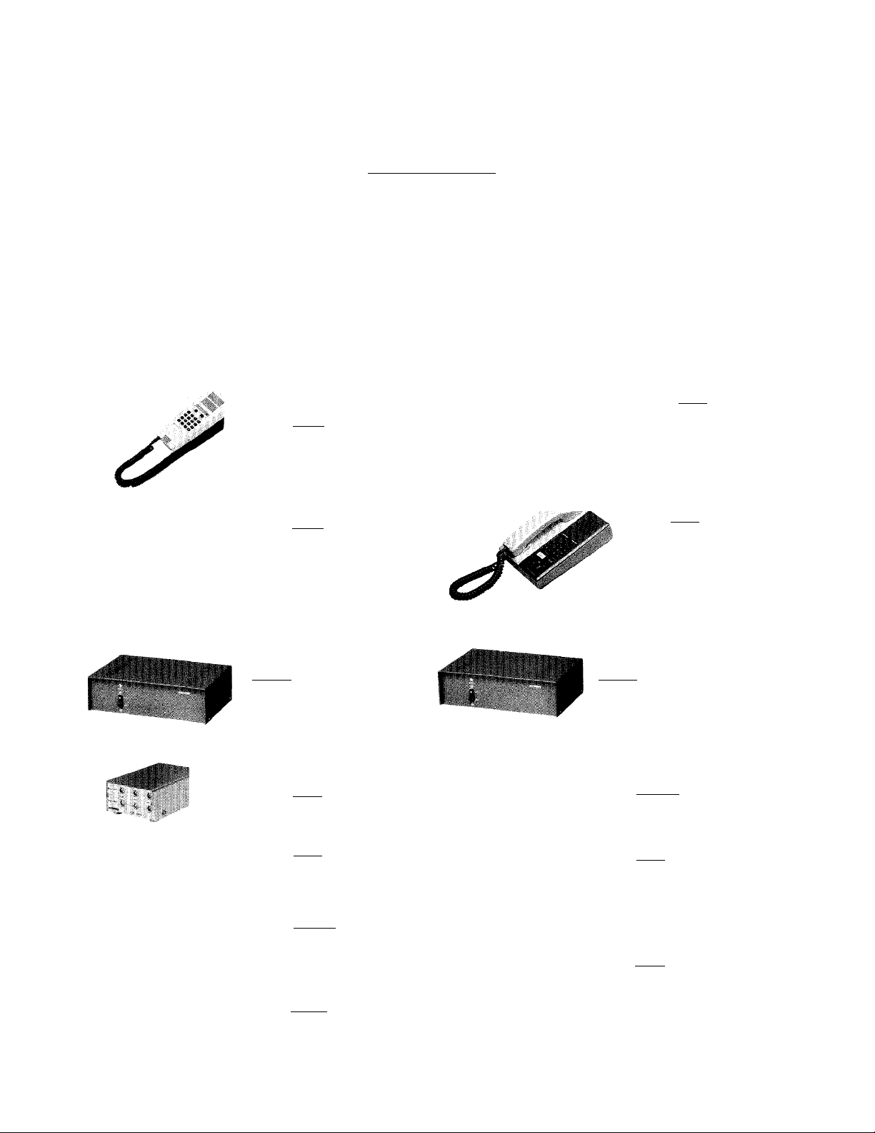
System Components
Central Exchange Unit
Station Equipment
III. RAX System Design and Components
Models: RAX-8, RAX-16, RAX-24
Central Exchange Unit for systems up to 8, 16 or 24 stations.
Includes a central terminal board and power supply unit.
Model: RA-A, Open voice master
station, with handset communication
capability. Desk/wall use.
Model: RA-C
Open voice sub station,
flush-mount (indoor
use only).
Accessories available;
Model: RA-B, Open voice master
station, flush mount (indoor
use only).
Model:
PG-10B (10 watts).
Standard Paging Amplifier,
with 100V or 8 ohms output.
Model: MC-A
Paging Adaptor.
Model: RC-A
Zone Paging Adaptor.
Model: SP-3NA
Standard 3 watt ceiling
speaker with built-in line
transformer.
Model: NBZ-M
Square frame for flush-mounting
of SP-3NA to ceiling.
I
I
Model: RA-D
Speaker-phone type
master.
Desk/wall use.
Model:
PG-10A (10 watts),
UL/CSA Approved Pagaing
Amplifier with 25V and
70V output (available only
in North America)
Model: PB-YKX
Talkback Adaptor.
Model: RC-B
Remote Control Adaptor
for operating external
devices.
Model: N-EA
Round frame for surface
mounting ofSP-3NAto ceiling.
- 3 -
Page 6
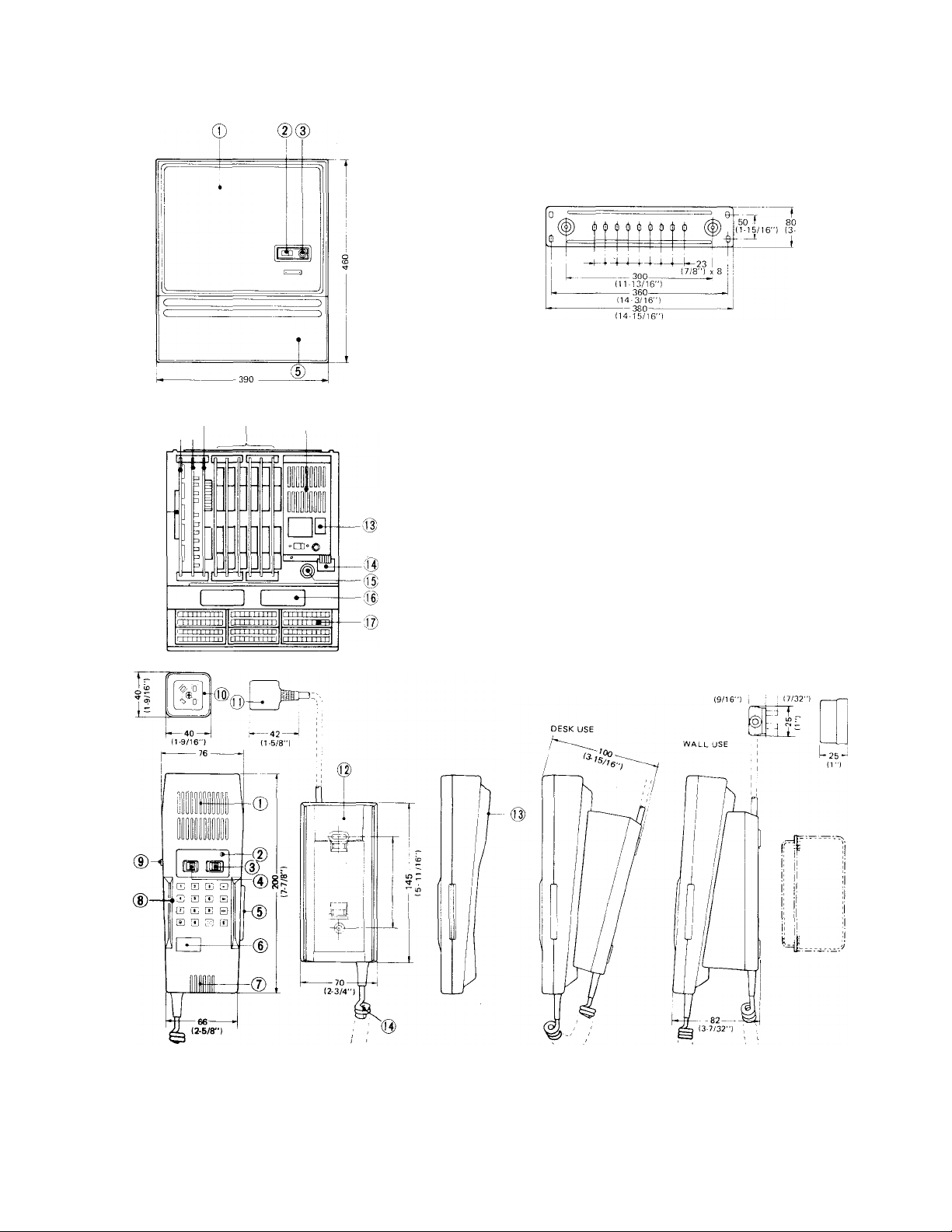
DIMENSIONS AND PARTS IDENTIFICATIONS
i®
; (D
(15-3/8")
— no -
(4-5/16":
Models: RAX-8, RAX-16, RAX-24
1. Main front cover
2. Power switch
3. Power lamp
4. Wall mounting bracket
5. Sub front cover
6. Screws for covers
7. Mother board
8. CPU Card (XC-060)
9. Function card (XC-061)
10. Voice-switching card (XC-062)
11. Subscriber card (XC-063)
12. Regulator unit
13. Automatic cutoff switch
(when cover is removed)
14. AC power terminals & ground terminal
15. Inlet for AC power line
16. Opening for cable from stations
17. Terminal block
n-1/32")
26—
15-.J 4 11
Model: RA-A
1. Open voice speaker
2. Call lamp (also for secretary transfer)
3. Volume control switch
4. Privacy switch
5. Bar switch for handset communication
6. Station No. plate
7. Microphone
8. Dial key pad
9. Talk button for paging/
simplex communication
10. DR-A receptacle
11. 4P plug
12. Pedestal (die cast)
13. Receiver for handset communication
14. Coil cord
- 4 -
Page 7
- y~' cJJt
csaciicD
CDSCD0<
mCDGDB
QQQE
CM o
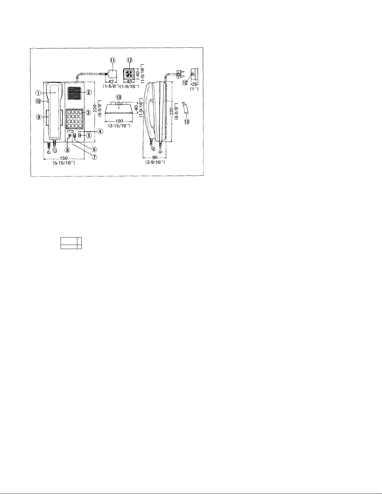
Model: RA-D (Speaker-phone type master)
1. Handset
2. Speaker
3. Dial key pad
4. Call LED (also for secretary transfer)
5. Volume control switch
6. Privacy switch
7. Station No. plate
8. Microphone
9. Directory card
10. TALK button
11. 4-pin plug w/2 m (6') cord
12. Receptacle
13. Stand
Model: RA-B (Open voice master station, flush mount)
1. Open voice speaker
2. Call lamp (also for secretary transfer)
3. Volume control switch
4. Privacy switch
5. Dial key pad
6. Microphone
7. Station No. plate
8. Terminals
9. Front panel (stainless steel)
@
-148-
(5-13/16")
-----
148
(5-13/16")
--------
33-.
(1-5/16‘
33^
1-5/16")
Model: RA-C (Open voice sub station, flush mount)
1. Open voice speaker
2. Call lamp
3. Volume control switch
4. Key pad
5. Microphone
6. Station No. plate
7. Terminals
8. Terminals for external switch
9. Front panel (stainless steel)
- 5
Page 8
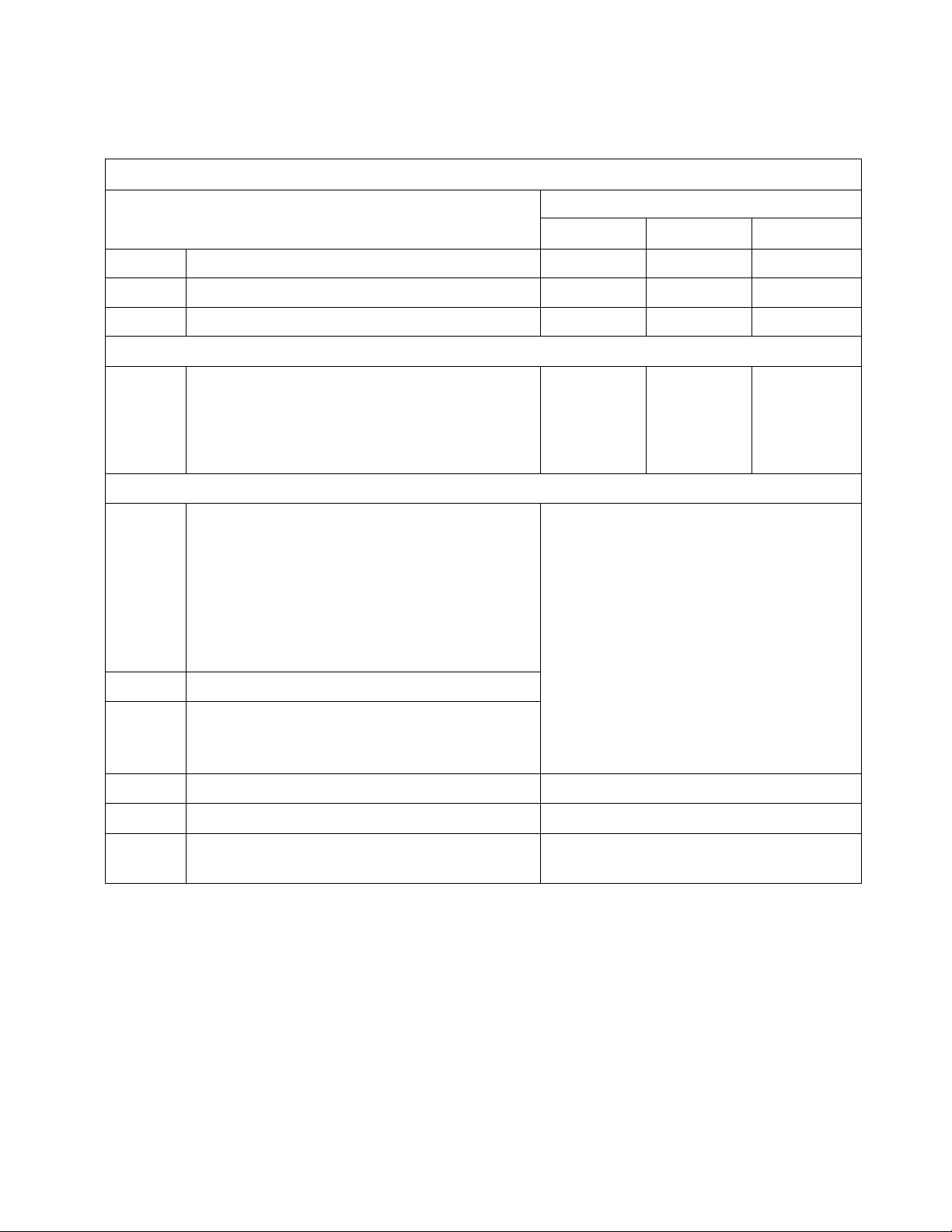
IV. RAX System Equipment Requirements
The RAX System Design Table below is to assist in determining the mix and quantity of RAX system components.
RAX SYSTEM DESIGN TABLE
RAX-8
RAX-16
RAX-24
RA-A
RA-D
RA-B
RA-C
PG-B
PG-10B
PG-A
PG-10A
SYSTEM COMPONENTS
Central Exchange Unit for up to 8 stations (with 2 XC-063)
Central Exchange Unit for up to 16 stations(with 4XC-063)
Central Exchange Unit for up to 24 stations (with 6XC-063)
STATION MODEL
Open voice master station, with handset
communication capability
Speaker-phone type master station
Open voice master station, flush-mount
Open voice sub station, flush-mount
OPTIONAL ACCESSORIES
Standard amplifier (available except in N. America)
low
UL/CSA approved amplifier
(available only in N. America)
low
QUANTITY OF COMPONENTS
RAX-8
1
max. 8
Up to 4 separate zones either for paging or
remote control
Each zone requires 1 PG-A or PG-B amplifier,
1 MC-A adaptor and a required number of
speakers. (Does not reduce station capacity)
OR
RAX-16
1
max. 16 max. 24
RAX-24
1
MC-A
SP-3NA
NBZ-M
N-EA
RC-A Zone paging adaptor
PB-YKX Talkback adaptor
RC-B
Note; System may include total of four MC-A and/or RC-B.
Paging adaptor
Standard 3 watt ceiling speaker
Square frame for SP-3NA.
Round frame for SP-3NA.
Remote control adaptor to be used in conjunction with
external devices such as lights, background music, etc.
When using one RC-A adaptor, as well as a
required number of speakers for each paging zone,
system can have only to use 1 each PG-A (or
PG-B) amplifier, MC-A adaptor, PB-YKX
talkback adaptor. (Does not reduce station
capacity)
1 for each paging zone where talkback is required.
1 for each zone where external device is located.
- 6 -
Page 9

V. Installation Guidelines
BE SURE TO TURN OFF RAX POWER SUPPLY BEFORE YOU OPEN THE UNIT OR
MAKE WIRING CONNECTIONS.
1. Central Exchange Unit (CEU);
* Select location for CED that will facilitate ease of access to the unit itself.
* Plug the power supply into a clear line. Interference on the power line may cause function error.
* Select a location that:
— has low humidity.
— is free of dust.
— is vibration free.
— is free of static electricity.
— is not near flammable or chemical product.
— is not close to high voltage equipment.
— is not within a strong magnetic field.
— is not near heating or air conditioning outlets or equipment.
— does not have direct sunlight.
— does not have temperature extremes: below 0°C (+32°F) or above + 40°C (+104°F).
2. Station;
* Each station must be home run wired to the C.E.U. individually, and must have individual station numbers.
* Follow location guidelines for the Central Exchange Unit when selecting station location.
* Avoid locations where temperature dips below —10°C (+14°F) or exceeds +60°C (+140°F).
* Select a most suitable type of station according to your communication requirements and environmental conditions.
3. Wiring;
* Use 2 twisted pairs for each station.
* Keep twisted pair cable well apart (over 50 cm or 20") from other cables such as heavy duty power lines, telephone
lines and/or paging amplifier output line (speak line).
4. Installation;
* In new construction install single-gang box for RA-A or RA-D stations or electrical box (see page 14) where
RA-B or RA-C stations are to be wall-mounted. The station will cover the hole, when installed.
Page 10

VI. Wiring
There are two basic wiring methods for RAX system.
In either case, you must use two twisted pair per station.
METHOD 1: 2 twisted pair in home run manner from each station to RAX Central Exchange Unit.
METHOD 2: More than one station can be run in multiple twisted pair cable.
DO NOT RUN SPEAKER LINE IN MULTIPLE PAIR CABLE FOR STATIONS.
* A combination of the above methods may also be used.
Refer to the chart below and select wire gauge required for your installation;
Wire size
Max. wiring distance
from station to
RAX CEU
0.5 mm
350 m
0.65 mm
600 m
0.8 mm 24AWG
900 m
1,200' 2,000'
22AWG
20AWG
3,000'
PAGIIMG/REMOTE CONTROL
The RAX system has the capacity of paging up to four separate zones and All Page.
Each zone requires one paging adaptor Model: MC-A, one amplifier and proper number of speakers for the amplifier output
(and one PB-YKX talkback paging adaptor is required for talkback). NOTE: All Page is a system function and does not require
special equipment or wiring.
NOTES; 1. If the system includes a remote control device, one paging terminal must be used for the RC-B remote control
adaptor. This will reduce the number of paging zones to 3.
2. Adding zones of paging and/or remote control does not reduce the station capacity of the system (i.e. a 24-
station system may have 24 stations plus 4 zones of paging and/or remote control).
3. If an RC-A adaptor is installed for each zone, only one MC-A paging adaptor and one amplifier is required for
zone page/AII Page. Talkback will require one PB-YKX talkback adaptor.
* *
WIRING REQUIRED
* 2 twisted pair cable or multiple twisted conductor cable may be used for connecting station to RAX terminal board
Wiring is polarized in each twisted pair. These cables must be twisted pair.
* Connection to MC-A adaptor requires two common plus one individual conductors from CEU terminal board.
* Regulator unit in CEU must be earth grounded.
* Do not run speaker line in the same cable with station wires.
-8-
Page 11

RAX SYSTEM DIAGRAM AND WIRING EXAMPLE
RAX Central
Excharge Unit
In case you want to include RA-C sub station in your RAX system, the RA-C station number must be assigned in consecutive
numerical sequence, either the number before or after the number of the master station, such as jlOl — |11| , |12| — [T^
Example: When RA-C sub station is connected to terminal No. 10 and RA-A (RA-D or RA-B) master station is connected to
terminal No. 11, pressing | | on RA-C station No. 10 calls master station No. 11 or vice versa. Any other station
may call the RA-C station No. 10 by pressing [jJ , .
NOTE: 1. The lower number in a pair of stations must be an even number, such as pT^ — [U] . • • ■ il8| — jl9| . . .
- [25] .
2. To make a pair of master/sub, master station may be connected to either station number in a pair, lower or
higher, as shown below;
Example: 10_________11
RA-A RA-C I Either combination will be acceptable for master/
RA-C RA-A I sub communication between Station No. 10 and 11,
- 9 -
Page 12

VII. RAX System Installation
(A) Mounting Central Exchange Equipment
* Be sure to turn off the power switch on the RAX C.E.U. before you open the unit OR make wiring connections.
*• The location of Central Exchange Equipment must meet the foilowing criteria;
1. Ambient temperature range: 0°C to +40°C (+32°F to +104°F),
2. Area must be as dust free as possible, and not too dry or too humid.
3. Units must be wall mounted.
4. Avoid static electricity.
There are" two basic methods (shown below) of mounting equipment.
If the adaptor(s) and amplifier(s) must be located in an area exposed to people, use of a cabinet is recommended to reduce the
possibility of someone changing level controls, or damaging wiring.
It is recommended that the Central Exchange Unit not be installed inside of the cabinet, which could restrict ventilation.
If the equipment is to be installed in an electrical room or cabinet, it is recommended that a piece of 1.2 cm (1/2") plywood of
adequate size be secured to the wall first and equipment then mounted to the plywood. This will insure adequate backing for
mounting screws, incoming cable distribution, and tie down.
-10-
Page 13

(B) RAX Central Exchange Unit Mounting Instructions
1. Central Exchange Unit shall be wall mounted
approximately 1.5 m (5 feet) high from the floor.
2. Install the mounting bracket to the gang boxes
with the provided screws.
Anchor the bracket with the provided screws or
bolts at 4 points.
3. Mount the RAX Central Exchange Unit onto the
bracket, and connect wires for both stations and
AC power line.
4. Replace the covers.
TOP VIEW MOUNTING BRACKET
41.75 mm(1-5/8")
CONNECTING WIRES
FOR STATIONS
RAX-24 TERMINAL LOCATIONS
REGULATOR UNIT
GROUNDING
WIRE
ANCHORING POINTS (2)
FOR RAX UNIT
MOUNTING 2- OR 4-GANG BOX
HARDWARE (FOR STATION CABLE)
1-GANG BOX
(FOR AC POWER LINE)
WALL
SCREW
For easy instaliation/removal of the
cover, leave space of 10 cm (4")
or more between a side of RAX
unit and the wall.
CZl
-10 cm or more
(4")
1101 — |33l Intercom station terminals
|p^[ , , |F^ , Paging/remote control terminals
NOTES: (1) Intercom station terminals on each Central Exchange Unit are;
^ in RAX-8
^ in RAX-16
QO] - [33] in RAX-24
(2) The number terminals 110| — [ij] , — [T^ .. and up to
'pair terminals' of master/sub.
-11-
Remote control output terminals
Power terminals for paging.
can be used as
Page 14

(C) Connecting Station Unit
RA-A, RA-D
(2) (1)
I
------
1 I
------
(4) (3)
~l
“T7'
4P plug
4P plug.........................Plug into the receptacle.
Receptacle
[n ' [U ' [H ' 0 Connect to each number terminal
(D) RA-A Wall Mounting Installation
1. Unscrew the RA-A pedestal base and separate the
cover from the chassis.
2. Reversely replace the cover to the chassis and
mount the RA-A pedestal base to one-gang box
with cover or to wall with the provided screws.
.................
Connect to Terminal section
of the Central Exchange Unit.
assigned on the Terminal section
of the Central Exchange Unit.
RA-B/RA-C
|~T| , [2] , 0,0 : Connect to each number
terminal assigned on the
Terminal section of
RAX CEU.
(E) RA-D Mounting Installation
For desk top use;
As shown, just insert the stand and fix with a screw provided.
For wall mounting;
RA-D is primarily designed for desk top use, but may
practically be used for wall mount (surface mount).
Remove a screw fixing terminal board. Slide down terminal
board, pull off 4P connector and separate terminal cord
from the chassis.
Attach terminal board to the wall with two screws. As
shown, pull out terminal cord either from top or bottom of
the unit. Attach connector and fit the unit onto the
terminal board.
Connector (male)
-12-
Page 15

Receptacle installation
RA-A'and RA-D have terminal cord of 2 m long (6-1/2"), male plug and shipped complete with female receptacle. When desk
mounting where cable must be run surface on the wall, fix the female receptacle to proper location and just plug in the male plug.
1. Mount the receptacle to wall as shown below;
2. When mounting the receptacle to flush plate, drill three holes on the flush plate and attach the receptacle with the screws
provided. Be careful not to install receptacle base upside down.
-13-
Page 16

(F) RA-B and RA-C Flush Mount Installation
RA-B/RAC
PANEL
RA-B/RA-C
UNIT
SCREW lx 4)
CIJ
□□□□
□□QO
□aon
1. Separate the RA-B/RA-C panel from the RA-B/RA-C
unit.
2. Attach the RA-B/RA-C unit to electrical box with the
supplied screws.
3. Replace the RA-B/RA-C panel to the unit with the
2 screws.
In N. America, please specify either BOWERS
703-SPL, RACO 952, APPLETON 3G-5075 or
equivalent.
ELECTRICAL
GANG BOX
RA-B/RA-C FLUSH-MOUNTING GUIDE
, 112 (4-7/16")
240
85 (3-5/16")
62 MIN
(2-7/16")
^ ^..........
90
(3-9/16")
194
(7-5/8")
203
(8")
1
209
(8-1/4")
SCREW
(4, 3/16" DIA.)
205
(8-1/16
4.5 (3/16")
9.2 (3/8")
, DIA.
195
(7-11/16")
(9-7/16"
rm
Vj
^ BOSS '
30 (1-3/16")
RA-B/RA-C SIDE & BACK VIEW
140
(5-1 /2")
When RA-B/RA-C are fulsh-mounted to wall, be sure that
two holes be opened for the bosses of 9.2 (3/8") diameter
and protruding 4.5 mm (3/16").
MINIMUM
MAXIMUM
Notes on installing station units;
(1) Avoid to locate the station unit in such places as closely surrounded by wall or other things, which may interfere with
voice-switching to function properly.
(2) Keep the station unit away from the paging speakers to avoid acoustic feedback in paging mode.
(G) Connecting AC Power Line and Grounding Wire
a| RAX-8,
□
As shown using standard screw driver, connect AC power line to |AC INPUT) terminals, and earth-ground wire to
IFG| terminal.
RAX-.16,
RAX-24
~ EARTH-GROUNDED
-14-
Page 17

(H) Connecting Paging Equipment
PAGING - ZONE PAGE APPLICATION WITHOUT TALKBACK
0 PAGING TO ONE ZONE (WITH BACKGROUND MUSIC)
RAX CENTRAL
EXCHANGE UNIT
CONNECT
03 - [33]
TO STATIONS
0 PAGING TO 4 ZONES (WITH BACKGROUND MUSIC)
Page 18

d) PAGING TO ONE ZONE, WITH REMOTE OPERATION OF POWERING AMPLIFIER ON WHEN PAGING,
USING RC-A ADAPTOR
(4) PAGING TO 4 ZONES, OR ALL PAGE, WITH ONE AMPLIFIER USING RC-A ADAPTOR
(WITHOUT BACKGROUND MUSIci
Notes: 1. RC-A adaptors must be located close to the RAX Central Exchange Unit.
2. The MC-A VOLUME CONTROL adjusts level of paging volume for 4 zones.
3. Output power of paging amp. must be sufficient to operate four paging zones simultaneously (All page).
-16-
Page 19

(I) Connecting Talkback Paging Equipment
(?) PAGING TO ONE ZONE WITH TALKBACK (WITH BACKGROUND MUSIC)
CONNETC
[3^ TO
STATIONS.
@ PAGING TO 4 ZONES WITH TALKBACK (WITHOUT BACKGROUND MUSIC)
Page 20

@ TALKBACK PAGING BY REMOTE OPERATION OF POWERING AMPLIFIER ON WHEN PAGING,
0 PAGING TO 4 ZONES WITH TALKBACK, WITH ONE AMPLIFIER USING RC-A ADAPTOR
Notes: 1. Talkback is not possible in All Page mode.
2. Output power of paging amplifier must be sufficient to operate 4 paging zones simultaneously (All Page).
3. Such paging accessories as RC-A's MC-A and PB-YKX must be installed close to central Exchange Unit.
4. Install a silicon diode (forward current; 100 mA, reverse voltage: 35V or more) between on MC-A and
|Pl~4l on RAX CEU.
ZONE 2
ZONE 4
RC-A PB-YKX RC-A PB-YKX
Note: Set the system selector switch
to the left position on PB-YKX.
18
RC-A PB-YKX RC-A PB-YKX
Page 21

(J) Connecting Remote Control Equipment, using the RC-B adaptor
NOTES:
(1) Wiring method is the same for either
momentary or alternate operation,
except for setting the selector switch as
below.
(2) When the RAX power supply is turned
off, the entire system becomes inope
rative, including remote operations.
(3) One remote control reduces one paging
zone.
METHOD #1 ALTERNATE OPERATION
Example: Turning lights ON and OFF
Operation: 1. Pick up handset.
2. Press I | (PAGE) button and zone number
button ( pT~|, I 2 I, I 3 [ or Q).
3. Momentarily depress [T] (TALK) button.
If you hear continuous tone, it means
lights are in OFF position. If you hear
intermittent tone, the lights are ON.
4. Momentarily depress | 0 | button, to reverse
ON/OFF mode. Press | • | (OFF) button
or hang up handset in RA-D.
NOTE: Remote control continues to be
working, if handset is hung up
when remote control is in operating
mode (in alternate operation)
METHOD #2 MOMENTARY OPERATION
Example: Opening electric door release.
Operation: 1. Pick up handset.
2. Press I | (PAGE) button and zone number
button (I 1 I, fy~| , fT] or H).
3. Momentarily depress [ t \ (TALK) button.
You will hear a continuous tone through
handset (door release is not activated).
4. Press and hold | 0 | button down, and
electric door release is activated. Door
will open. Press | » [ (OFF) button or hang
up handset in RA-D.
-19-
Page 22

(K)AII Call
All call means that user can page through all stations Instead of separate paging speakers.
Note: All call has the top priority over other functions and overrides existing conversations and/or stations in privacy mode/
secretary transfer mode.
-20-
Page 23

OPERATIONS
1. Calling & Communication (RA-A, RA-B & RA-D)
Press two-digit buttons of desired station (i.e.l 1 I , | 0 | for station #10).
Note: Station numbers available: from 110 | to I If I for RAX-8 system
from 110 I to I 25 I for RAX-16 system
from to I 33 I for RAX-24 system
The line is established when a short tone sounds as well as call LED gets illuminated, and talk handsfree. After
communication, press p»~| (OFF) button.
When Busy Tone is heard; Short intermittent tone means called station is occupied.
You may press | * | button or hang up handset in RA-D to disconnect OR press | 0 |
(ME MORY) button to leave request for automatic call back. You will be automatically
connected as soon as called station completes its conversation.
If your message is urgent; You may break in on the called station's conversation by pressing [ 0 | button. Called
(Urgent Message or Break-in) station will receive signal and place present conversation on HOLD to reply.
When Privacy Tone is heard; Longer intermittent tone indicates called station is in Privacy Mode. You may wait for
station to release from Privacy Mode, as call tone will signal at the station in Privacy Mode
for about 4 seconds.
2. Rceiving a call (RA-A, RA-B, RA-D & RA-C)
An incoming call is annunciated by a short tone and call LED illumination.
Reply hands free.
In RA-A you may pick up the unit and depress and hold the bar switch and in RA-D,
pick up handset for private handset communication. After communication, press the
I » I (OFF) button or hang up handset in RA-D,
Urgent Message Break-in Signal; A short tone, like the call tone, received during a conversation indicates another station
is trying to reach you with an urgent message.
Press [ 0 I (MEMORY) button to place present call on HOLD and automatically connect
you to the calling station.
Touch I • I (OFF) button or hang up handset in RA-D to restore connection to station
on HOLD and resume conversation.
Privacy I
To block out incoming calls and prevent monitoring, slide PRIVACY SWITCH to the right position. '
An incoming call is announciated by longer intermittent tone signalling about 4 seconds. Press | >i< | (TEMPORARY
PRIVACY) button to reply hands free or, in RA-A, pick up the unit and hold the bar switch or, in RA-D, pick up hand
set to reply. After communication press [ > | (OFF) button or hang up handset in RA-D and the station automatically
returns to PRIVACY mode.
To release from Privacy Mode, slide PRIVACY SWITCH to the left position.'
* Setting or releasing from Privacy Mode must be made while your station is in standby mode.
-----------------
J
----
------------------
B
^
-21-
Page 24

3. Call Transfer;
To transfer a call from one station to another, press [ ® | (MEMORY), number of station where call is to be transferred
and, after communication line is established, press | 7 | (TRANSFER) button.
4. Call Holding;
To place present communication on HOLD, press (MEMORY) button. Press [~^ (MEMORY) button orfV] (OFF)
button or hang up handset in RA-D to restore connection to station on HOLD and resume conversation.
5. Secretary Transfer;
Press I ® I (MEMORY) button and station number buttons to have your calls answered in your absence by your secretary
or another person you want to receive your calls. -»• Call LED flickers.
Press I 0 I (CLEAR) and| 7 | (TRANSFER) buttons to cancel secretary transfer mode.
6. Press-to-Talk Operation;
When you communicate with a station situated in a noisy area, you may press [T] (TALK) button to talk and release
to listen.
7. Master/Sub Communication;
For communication between a paired master & sub stations, press | | button to call and communicate as soon as the
line is established.
After communication, press | • | (OFF) button at either station or hang up handset in RA-D.
8. All Page;
To page all zones in your system through speakers, pressfx] (PAGE) button and (ALL PAGE) button, then depress
and hold | t | (TALK) button and page. TALKBACK IS NOT AVAILABLE IN ALL PAGE MODE. The paged person
may reply to the paging person from nearest station by pressing | 6 | button.
Press'! * * ! (OFF) button or hang up handset in RA-D when page message is completed.
9. Zone Page;
To page one selected zone in your system through speakers, press j | (PAGE) and zone number (| 1 j , | 2 j, | 3 j or
I 4 I ) buttons, then depress and hold down | t | (TALK) button and page.
When talkback is included, release fT] (TALK) button for reply.
When talkback is not included, the paged person any reply from the nearest station by pressing [~6~| button.
10. All Call;
To page through individual stations, press j 5 j and make announcement by depressing and holding [ t | (TALK) button.
The person paged can go to the nearest station, press | 5 | button and can reply to the All Call.
The All Call Call-back Automatic Connection is valid for about 30 second, after the announcement is completed.
* Operational notes:
(1) For handset communication, hold the RA-A bottom side to your ear and keep the bar switch in depressed position.
(2) Communication should be made within an operable distance.
I n RA-A, talk toward the microphone from the front for best results.
(3) Do not put papers or books near RA-A and RA-D units to ensure best performance.
(4) In RA-D, TALK button in handset works for [ t | (TALK) button on the dial key pad.
-22-
Page 25

Yin. RAX System Specifications
1. Central Exchange Unit: RAX-8, RAX-16, RAX-24
* Power source AC110-125V, AC220-240V, 50/60Hz.
* Power consumption Maximum 68W, 23W in standby mode (RAX-24)
Maximum 50W, 20W in standby mode (RAX-16)
Maximum 35W, 18W in standby mode (RAX-8)
* Station capacity 8 in RAX-8, 16 in RAX-16, 24 in RAX-24
* Trunkage capacity 2 channels for communication and one separate channel for paging/remote control.
* Dialing Mono frequency-duty modulation
* Line scanning Voltage level detection by time sharing
* Internal network PAM time sharing multi-network
* Line impedance 600 ohm
* Permitted line resistance 64 ohm (Loop)
* Wiring Home run CEU - RA-A
CEU — RA-B
CEU — RA-D
CEU — RA-C
CEU - MC-A
CEU - PB-YKX . . . . 3 wires
CEU — RC-A
CEU — RC-B
* Ambient temperature 0°C (-h32°F ) ~ 40°C (-H04°F)
* Ambient humidity Under 80% (yearly average)
* Installation Wall mount (including terminal board, power supply unit).
...................
...................
...................
.................
...............
.................
.................
2 twisted pairs
2 twisted pairs
2 twisted pairs
2 twisted pairs
3 wires
3 wires
5 wires
2. Open voice station, with handset communication capability: RA-A (Desk/Wall use)
Speaker-phone type station: RA-D (Desk/Wall use)
Power source
Current consumption
Communication
Calling
Key pad
Station selection
Mounting
DC 24V supplied by RAX Central Exchange Unit.
DC 10mA (maximum)
Loudspeaking voice-actuated.
Voice-actuated with handset
Pre-tone and call LED Illumination
16 touch key buttons
2-digit dial ( pf^ - [^ )
Desk/Wall use
3. Open voice station: RA-B (Flush-mount)
Power source
Current consumption
Communication
Calling
Key pad
Station selection
Mounting
Front panel
DC 24V supplied by RAX Central Exchange Unit.
DC 10mA (maximum)
Loudspeaking voice-actuated
Pre-tone and call LED illumination
16-touch key buttons
2-digit dial ( pml - |3^ )
Flush-mount to wall
Stainless steel
-23-
Page 26

IX. RAX System Specifications (continued)
4. Open voice sub station: RA-C (Flush-mount)
Power source
Current consumption
Communication
Calling
Key pad
Station selection
Mounting
Front panel
5. Paging adaptor: MC-A
* Power source
* Current consumption
6. Talkback adaptor: PB-YKX
* Power source
* Current consumtion
7. Remote control adaptor: RC-A, RC-B
DC 24V supplied by Central Exchange Unit.
DC 10mA (maximum)
Loudspeaking voice-actuated
Pre-tone and call LED illumination
2-touch key buttons
1 button (I 1)
Flush-mount
Stainless steel
DC 24V supplied by Central Exchange Unit.%
Maximum 20mA in standby mode
Maximum 50mA (max.) in paging mode
DC 24V supplied by Central Exchange Unit.
Maximum 2mA in standby mode
Maximum 40mA (max.) in talkback paging mode
Power source
Current consumption
Permitted contact capacity
PERMITTED LINE DISTANCE
RAX CEU - RA-A, RA-C
RA-B
RA-D
RAX CEU - MC-A
RC-A
RC-B
RAX-CEU - PB-YKX
DC 24V supplied by RAX Central Exchange Unit
Maximum 40mA (max.)
Maximum AC 120V, 3A.
Maximum DC 24V, 3A.
Minimum applicable load: DC 5V, 100mA.
0.5 mm 0.65 mm
350 m
90 m
530 m
600 m
150 m
890 m
0.8 mm
900 m
230 m
1,350 m
24 AWG 22 AWG 20 AWG
1,200' 2,000' 3,000'
300'
1,800'
500' 800'
3,000'
1
4,500'
-24-
Page 27

X. Post Installation System Testing
Once installation is finished, testing is recommended prior to indoctrination of used personnel regarding operation of the system.
Proper installation of the RAX system, and its full range of communication functions, can be tested with three simple steps.
Step 1: Checking Station-to-Station Communication
• Select one station as the key station. Label it "S-1". Label remaining stations "S-2" through "S-n".
• Call S-2 from S-1 and confirm communication.
• Call S-1 from S-2 and confirm communication.
• Repeat process from S-1 to S-n until each station in the system has been tested.
Step 2: Checking Busy Tone signal
Using three stations (S-1, S-2 and S-3)
• Call S-1 from S-2.
• While S-2 is calling S-1, call S-2 from S-3 to confirm that Busy tone signal is heard.
Step 3: Checking Paging Function (If applicable)
Using S-1, page each zone (touch |j^ and 1,2,3 or 4), then depress Talk button to confirm paging is transmitted
to selected zone (If talkback function is included, release | t \ Talk button to confirm talkback). To check remote
control operation, touch | | and zone number button connected to the external devices, and momentarily depress [ t |
Talk button in handset. Depress button to confirm either continuous or intermittent tone.
Upon completion of the above tests, if any of the remaining communication functions are not found to work as pre
scribed in the Operations Manual, the cause is not due to improper installation. Rather, the Central Exchange Unit must
be checked. If this is the case, an Aiphone Specialist must be consulted.
XL User Indoctrination
Upon completion of post installation testing and confirmation of the system being fully operable, used personnel should
be indoctrinated as to how to use the system.
The Operation Manual clearly describes all of the communication features of the system. A complete understanding of
the operation of the system by those who will be using it well avoid post installation call backs and related service.
* Special Instructions:
(1) Please turn on the power switch on the RAX C.E.U. after all the equipment wiring is completed. If intercom sta-
tion(s) would be connected after system powered on, the station(s) would not work properly. Please turn off the
power switch temporarily for about 10 seconds.
(2) Do not make temporary operation of turning ON and OFF power switch again and again. At least 3 seconds have to
elapse between ON and OFF operations.
-25-
Page 28

XII. Trouble Shooting Guide
Incorrect wiring can be detected by the trouble mode as shown below;
Terminals
Wiring mode
1 and 2 * No LED is lit.
* No dial tone.
* No communication.
1 or 2
3 and 4 * No LED is lit.
3or4
1 and 3 * LED is lit.
* LED is lit.
* Dial tone is heard.
* No communication (cannot transmit
voice signal to the other station)
* No dial tone.
* No communication.
* LED is lit (can select, but cannot be
called).
* No dial tone.
* No communication (can transmit
voice signal to the other station)
* No dial tone.
* No communication (cannot transmit
voice signal to the other station)
OPEN
SHORT
* LED is lit. (cannot select)
* Dial tone is heard (can be called)
* No communication (cannot transmit
voice signal to the other station)
* LED is lit.
* No dial tone.
* No communication (can transmit voice
signal to the other station)
2 and 4
1,2,3 and 4
1 and 3
1 and 4
2 and 3
2 and 4
* LED is lit.
* No dial tone.
* No communication (cannot transmit
voice signal to the other station).
* LED is lit while depressing a number
button, and goes out upon releasing.
* No dial tone.
-26-
Page 29

XII. Trouble Shooting Guide (continued)
Terminals
1 ^^2
1 ^^3
1 ^-^4
2^-^3
2^-3>4
1 ^^3
and
2<^-^4
Wiring mode
* LED is lit.
* Dial tone is heard.
* Can communicate.
* LED is lit while dialing and goes out, upon releasing.
* No dial tone.
Wire crossed
XIII. Servicing
1. Be sure to turn off power switch on RAX C.E.U, before you remove the cover of Central Exchange Unit.
2. Removing the cover of Central Exchange Unit will automatically activate the automatic switch and shut off the power.
When the system has to be powered for testing, the automatic cutoff switch must be in a depressed position.
3. As the printed circuit boards in Central Exchange Unit employ MOS-ICs, do not touch the printed circuit boards. Doing
so may damage the printed circuit boards with static electricity discharged from your fingers.
4. Before removing the printed circuit board: XC-063 (subscriber card), wait until all three (3) LEDs go out on the mother
board (XC-064) after the power is off.
5. Before replacing any station, be sure to turn off the power supply.
6. When your RAX system includes paging amplifier(s) or remote control devices, turning on and off will cause noise through
paging speakers and switchover of the remote control ON/OFF mode of the remote control devices. This is not due to
equipment failure but rather what occurs when the power supply is turned on or off.
7. When replacing Cards, locate the Card in the right position by matching color of the Card with that on the chassis. Locate
the subscriber card (XC-063) as from the position next to the voice-switching card (XC-062).
IIP
 Loading...