

Page 1
AlPHONE
PAGING AMPLIFIER
MODELS: PG-10A (10 watts output)
PG-30A (30 watts output)
PG-60A (60 watts output)
AlPHONE PG-A paging amplifiers are designed for use with AlPHONE paging intercoms. 10 watts,
30 watts and 60 watts ampifiers are available and may be installed in multiples for greater output.
- INSTRUCTIONS -
. This symbol on the nameplate means the product
Ly is Listed by Underwriters Laboratories Inc.
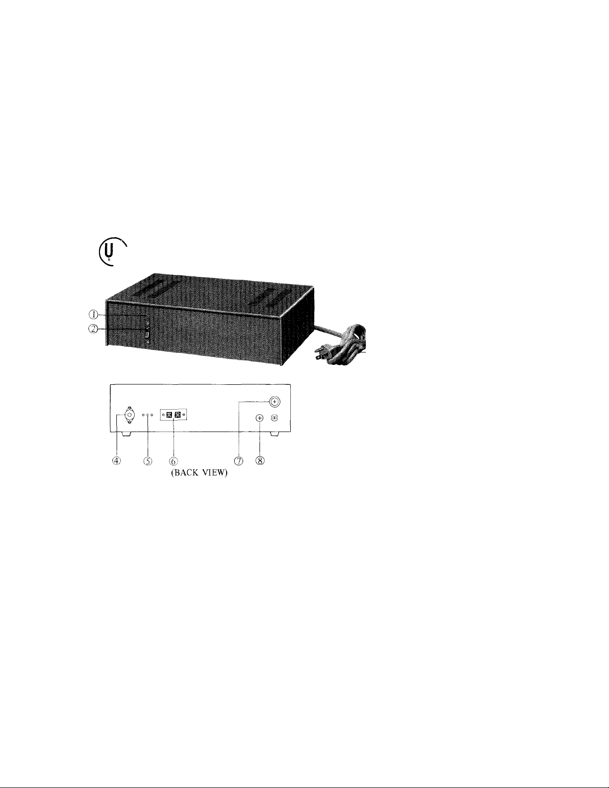
NAMES AND FUNCTIONS
(T) Power lamp
@ Power switch
(3) AC cord
(i) Output (25/70.7 volt alternative)
(5) Circuit breaker
SPECIFICATIONS
* Power output;
* Distortion;
* Frequency response;
* Input;
* Output;
* Power requirements;
* Power consumption;
* Dimensions;
Weight:
PG-lOA
PG-30A..............30 watts rms
PG-60A..............60 watts rms
Less than 3% at 1,000 Hz rated output
±3 db, 100- 15,000 Hz
100 mV for rated output
25 volts and 70.7 volts balanced
120 volts AC, 50/60 Hz
PG-lOA..............30 watts
PG-30A..............75 watts
PG-60A..............130 watts
PG-lOA
245mm x 77mm x 152mm, 9-11/16" x 3-1/16" x 6"
PG-30A & PG-60A
340mm x 95mm x 205mm, 13-5/16" x 3-3/4" x 8-1/16"
PG-lOA
PG-30A
PG-60A................6.5 Kg, 14.3 LBS
..............
................
................
10 watts rms
2.7 Kg, 6.0 LBS
5.0 Kg, 11.0 LBS
@ Input terminals (A & E)
@ Fuse holder
(D G terminal for grounding
Page 2
FEATURES
Designed for use with AIPHONE intercoms in conjunction with paging adaptor.
Full range volume and tone controls on paging adaptor.
Amplifier output may be either 25V or 70.7V constant voltage balanced loads.
Complimentary transistor at the output stage ensures extreamly low distortion and high damping factor.
* Circuit breaker protects internal circuit against overloaded or shorted output line.
* May be shelf or wall mounted.
INSTALLATION
Do not attempt to install your PG-A amplifier until you have read and thoroughly understood the installation
procedure. Aiphone’s warranty for the amplifier and the system is void if amplifier is installed in a manner other than
described in this manual.
ADAPTOR REQUIREMENTS
The following AIPHONE intercoms have paging capability and may be connected to PG-A amplifier in conjunction
with a paging adaptor. The type of adaptor must be decided according to the type of intercom system you install and the
paging mode you wish to have. Each paging block requires one PG-A amplifier and appropriate number of speakers.
TYPE OF
INTERCOM
® TA-F
® TA-H
(3) TA-Y
0 TS-K
@ KAH one PA-1
STRAIGHT PAGING
one PG-U
one PG-U
one PG-U one PG-U and one PA-B per block
© TB-F one PB-1
© TB-H one PB-1
® MC-3 one MC-A
ADAPTOR REQUIREMENTS
BLOCK PAGING
TALKBACK PAGING
not available one PG-U and one PA-B
one PG-U and one PA-B per block one PG-U and one PA-B per block
one PG-U and one PA-B per block
one PA-1 per block
one PA-2 per block
not available one PB-1 and one PB-2
one PB-1 per block one PB-1 and one PB-2 per block
not available not available
Begin your installation by connecting the paging adaptor to your intercom system (and background music source
if required) by referring to the instruction sheet of the paging adaptor packed with each unit. Requirements stated on
the instruction sheet of the paging adaptor MUST BE MET.
After completing installation of both intercom system and the paging adaptor, then you may proceed to installation
of PG-A amplifier. Unplug both power supply for intercom system and amplifier while making wiring connections.
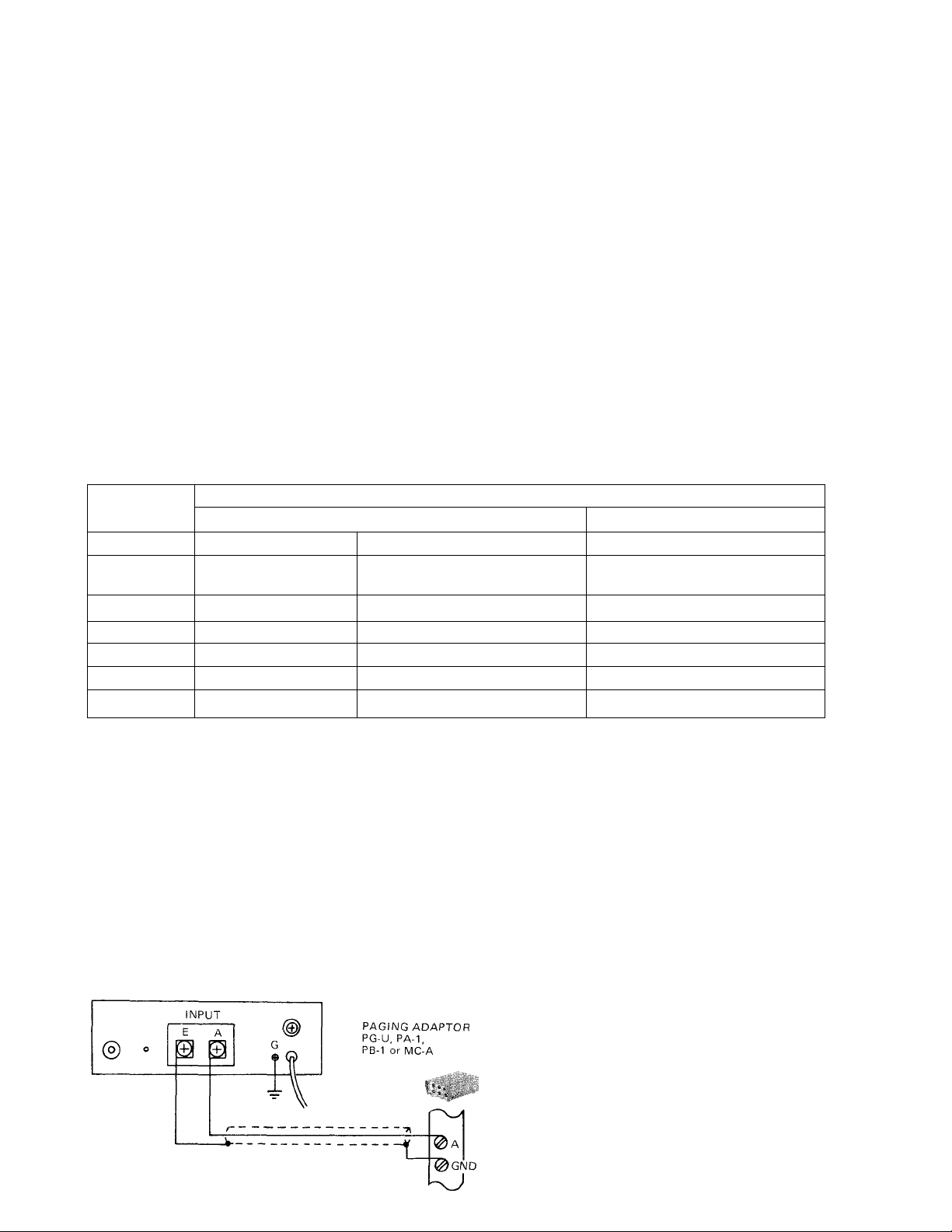
AMPLIEIER INPUT CONNECTIONS
The greater the distance between the paging adaptor and the amplifier will increase the possibility of picking up
R.F. signals or electrical noise.
The paging adaptor and amplifier should be located as close as possible to each other and shielded cable should
always be used to connect them.
PAGING AMPLIFIER
PG-10A, PG-30A or PG-60A
1) Connect output A terminal on paging
adaptor to input A terminal on PG-A
amplifier.
2) Connect output GND terminal on paging
adaptor to input E terminal on PG-A
amplifier.
* G terminal which has a green colored screw
head must be ground for avoiding electric
shock or hazard.
Page 3

AMPLIFIER OUTPUT CONNECTIONS
Pull out the output plug and remove the cap. Insert
speaker line, thru the cap, one into common pin indicated
COM and the other into either 25V or 70.7V pin. Attach
the conductors to the pins with low heat soldering. Replace
the cap and insert the output plug into recepticle.
OUTPUT
COM D D
70V
©
-CONDUCTORS MUST BE ATTACHED
TO PINS WITH SOLDERING
- OUTPUT PLUG
SPEAKER REQUIREMENTS
IMPORTANT
- CAP
-2-CONDUCTORS (SPEAKER LINE)
1 It is imperative that the total power consumed for speakers MUST NOT EXCEED the output power of amplifier
i.e. maximum 10 watts for PG-lOA, 30 watts for PG-30A and 60 watts for PG-60A. Greater output than 60 watts
may be obtained by multiple installation of amplifiers. Refer to drawing below.
2 It is NOT REQUIRED to have a dummy load when the power consumed for speakers is less than the output power
of amplifier.
3 A low impedance speaker such as 8 ohm horn must be installed using a matching transformer.
4 The total impedance of all speakers, matching transformers, and length of speakers run must be equal or more
than the output impedance of the amplifier. Refer to chart below. After computing the resistance of your
speaker, transformers, and speaker line, add a resistor in series to speaker line to increase impedance to match chart.
MULTPLE INSTALLATION
PAGING
ADAPTOR
OUTPUT IMPEDANCE
25 volt line 70.7 volt line
PG-lOA 62.5 ohms 500 ohms
PG-30A 21 ohms ; 167 ohms
PG-60A 10.5 ohms \ 83 ohms
* Output of each amplifier (speaker line) MUST BE SEPARATE.
INSTALLATION EXAMPLE
1) This example illustrates connection of TB-H system with single zone paging without talkback.
2) In this example button #6 on each phone operates paging.
NOTE: Each paging adaptor requires different wiring.
Please refer to the instruction sheet packed with the adaptor you are going to install.
Page 4

WALL MOUNTING INSTALLATION
Your PG-A amplifier is designed either for shelf or wall mounting.
Please avoid placing the amplifier on dusty or humid floor.
1) Each amplifier is shipped complete with screws and bracket for
wall mounting.
2) Attach the bracket to the bottom of amplifier.
3) Mount the amplifier upon the screws protruding from the wall.
4) Fix the attached bracket to the wall with the supplied screw.
FIELD SERVICING
BREAKER
Your PG-A amplifier is equipped with a circuit breaker to protect the internal circuit from overloads or
shorts in speaker line.
If you do not have any output to the speakers, make the following checks:
1. Check A.C. outlet ^ Unplug amplifier from A.C.
2. Check speaker line for either overloads, shorts, or opens — and repair.
3. Plug PG-A amplifier into A.C. outlet and press circuit breaker button.
FUSE REPLACEMENT
A slow blow fuse (lA for 10, 2A for 30, 3A for 60) is located on the rear of each amplifier. A blown
fuse is generally caused by internal circuitry. Turn amplifier off and replace fuse. If the replacement fuse also goes out,
refer amplifier to qualified personnel.
We at AlPHONE are proud of our products. Our designers and engineers strive to bring you the finest in communication
equipment. Each item has been carefully tested and inspected before leaving our factory. Properly installed and used, your
Aiphone intercom system should give years of troublefree service.
We are pleased to offer the following warranty:
z WWtWTW WITH WIirr-wwm,Trrr-r-Ttz JJSIItTTZJJJrf III lIIUTITITJMIJ^I-wrlTrXrrmrTW TiiirmmrrTrrTrtrw-rri¥~
WARRANTY
Aiphone warrants its products to be free from defects of material and workmanship under normal
use and service for a period of one year after delivery to the ultimate user and will repair free of
charge or replace at no charge, should it become defective upon which examination shall disclose
to be defective and under warranty. Aiphone reserves unto itself the sole right to make the final
decision whether there is a defect in materials and/or workmanship; and whether or not the prod
uct is within the warranty.
This warranty shall not apply to any Aiphone product which has been subject to misuse, neglect,
accident, or to use in violation of instructions furnished, nor extended to units which have been
repaired or altered outside of the factory.
This warranty does not cover batteries or damage caused by batteries used in connection with the
product.
This warranty covers bench repairs only, and any repairs must be made at the shop or place des
ignated in writing by Aiphone. Aiphone will not be responsible for any costs incurred involving on
site service calls.
-------KF--------------------------------------------------------------------------------------------
Aiphone Co., Ltd.,“ Nagoya, Japan
Aiphone Corporation, Bellevue, Washington
PG-AKUL) 1182®
ALL OVER THE WORLD AIPHONE
Printed in Japan
 Loading...