

Page 1
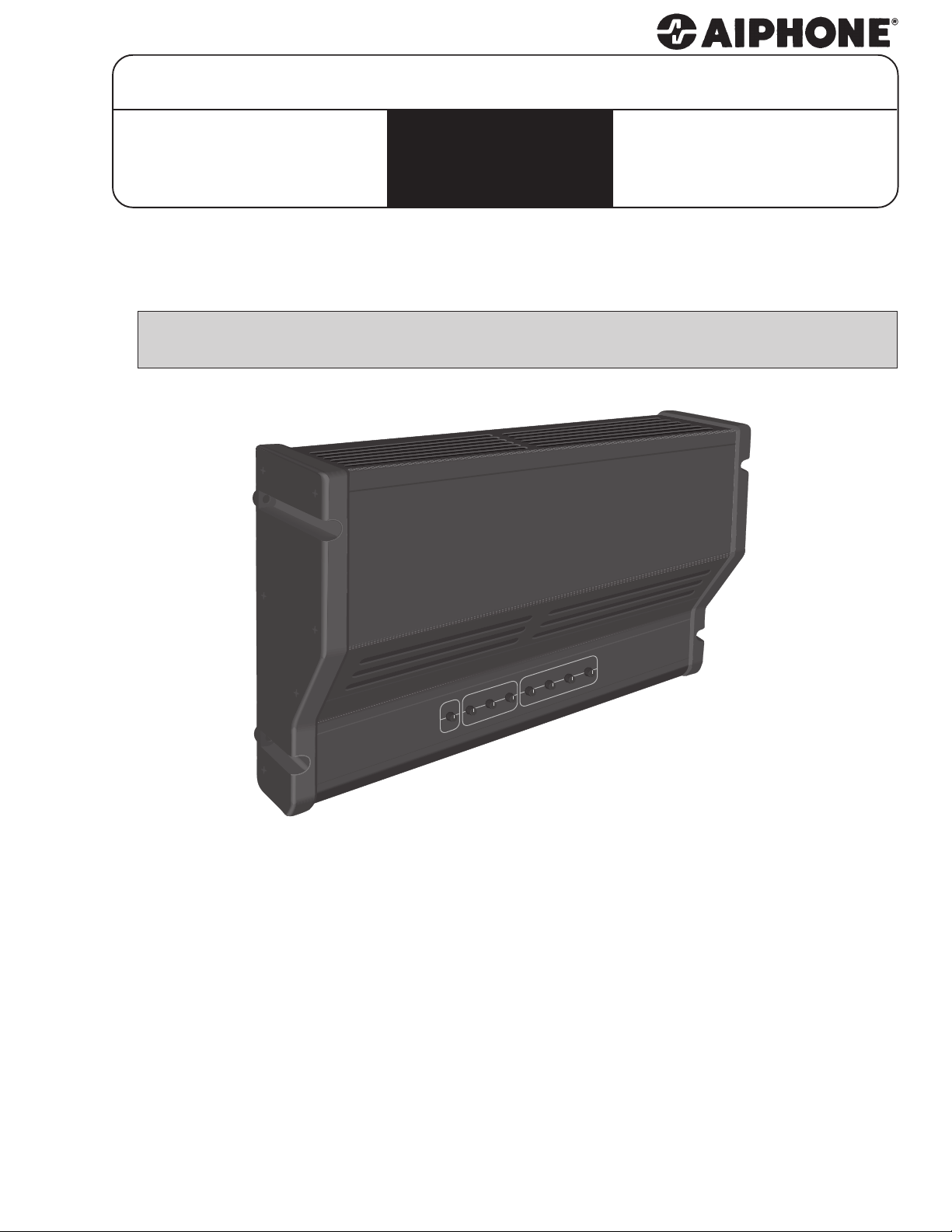
PAGING AMPLIFIER
PG-20C
PG-50C
PG-100C
- INSTRUCTIONS -
PG-C Series Amplifiers, with built-in paging adaptors, are designed for use with Aiphone
paging/intercom systems.
PRODUCT FEATURES
1
1
20, 50 and 100 watt models are available.
AIPHONE
PG-100C
PLIFIER
AM
ADAPTOR
TEL /MIC
MUSIC
PRETONE
VOL
VOL
VOL
TREBLE
BASS
VOL
TREBLE
BASS
• Built-in Aiphone paging adaptors (MC-A, PD-1, PD-2).
• For use with Aiphone intercom systems MC-60/4, TD-H/Z,
RCX, YKX, or as a stand-alone.
• Telephone system interface for paging.
• Full range volume and tone controls.
• Short circuit and overload protected.
• Separate bass and treble controls for paging and music.
• Adjustable background music volume control.
• Adjustable paging pre-tone volume control.
• Dry contact or VOX music mute (Mic or Tel).
• Black anodized brushed aluminum finish
with ABS end panels.
• NRTL/C certified (complies with both UL & CSA standards).
Page 2
NAMES AND FUNCTIONS
12
ON
2
2
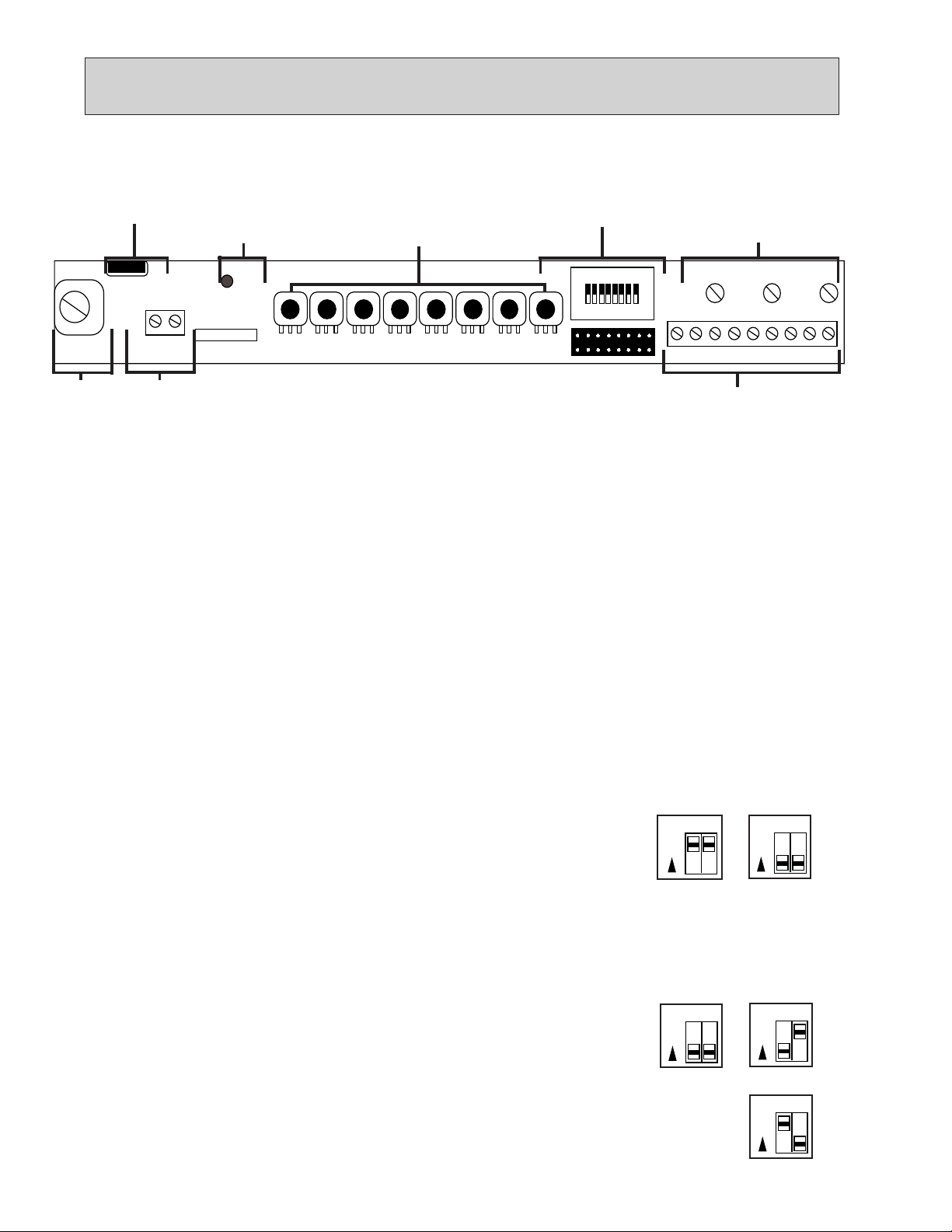
The following controls and terminals may be accessed by removing the screw on
the bottom of the unit and lifting the lower cover.
1. Fuse
2. Power
3. Volume, Bass &
LED
F1
GND
TB1
12
6. Ground
1. FUSE
2. POWER L.E.D.
3. VOLUME, BASS & TREBLE CONTROLS
7. Output
Replace fuse with 3AG SloBlo's only in the following ratings:
PG-20C 3/4 Amp PG-50C 1-1/4 Amp PG-100C 2 Amp
Indicates that the amplifier is on or off.
These controls are normally set at the time of installation, purposely protruding only slightly from the
cover so that they can be adjusted if necessary, but are less susceptible to accidental change.
A) PRE-TONE Volume - P1
Adjusts the level of the pre-tone signal over the speakers.
B) MUSIC/AUX Volume - P2, Bass - P3, Treble - P4
Adjusts the level, treble and bass of the background music.
LD1
POWER
A1002
SER.
P1 P2 P3 P4 P5 P6 P7 P8
Treble Controls
4. Dip Switches
SW1
ON
5. Preset
Controls
VOXP9NOISE
P10
21345678
LEV
P11
8. Terminals 1 - 9
9
C) TEL/MIC Volume - P5, Bass - P6, Treble - P7
Adjusts the level of the telephone/microphone input separately from the music controls.
D) Adaptor Volume - P8
Adjusts the volume level of the paging via the Aiphone intercom/paging system.
4. DIP SWITCHES
A) Dip switches 1 & 2 - Telephone/Microphone
If a telephone system is used, set both switches to the ON position.
If an external microphone is used, set both switches to the OFF position.
B) Dip switch 3 - VOX (Voice activated switch)
Set this switch to the ON position if VOX music muting is going to be used with tel/mic paging.
C) Dip switches 4 & 5 - Talk battery
Set both switches to the ON position to enable this function. This option provides a talk battery to the
telephone set or telephone system C.O. trunk.
D) Dip switch 6 - Pre-tone
Set this switch to the ON position to enable the Pre-tone function.
E) Dip switches 7 & 8 - Paging adaptor option
For PD-1 adaptor, set both switches to the OFF position.
(The PD-1 is used for paging in the TD-H and TD-Z systems)
For PD-2 adaptor, set switch 7 to the OFF position and switch 8 to the ON position.
(The PD-2 is used for paging and talkback in the TD-H and TD-Z systems)
For MC-A adaptor, set switch 7 to the ON position and switch 8 to the OFF position.
(The MC-A is used for paging with the MC-60/4, RCX, and YKX systems)
Telephone
PD-1
78
ON
Microphone
12
ON
PD-2
78
ON
MC-A
78
ON
2
Page 3

NAMES AND FUNCTIONS - CONT.
2
2
5. PRESET CONTROLS
A) VOX - P9 (Voice activated switch)
This pot adjusts the sensitivity of the VOX threshold of the tel/mic input. Make adjustments as follows:
1) Set the VOX control fully counter clockwise (CCW) (background music should be on).
2) While someone is talking in the page mode, slowly turn the control clockwise (CW) until
the VOX circuit triggers and the background music cuts off.
3) Turn the control an additional 1/8 turn CW and leave at this setting.
If the VOX function has a tendency to drop out, slightly increase (CW) the control setting.
B) Noise - P10 (Talkback background noise balance)
This pot cancels the background noise in the talkback circuit which may be induced into the speaker
wiring by an outside source. (For use with the PD-2 talkback paging adaptor only.)
C) Level - P11
This pot sets the talkback level of the amplifier. (For use with the PD-2 talkback paging adaptor only.)
6. GROUND TERMINAL
A chassis ground has been provided to allow separate grounding of the unit, if required.
7. OUTPUT
Connect speaker wires to the terminals labelled OUTPUT. The rated output of all amplifiers is 70V RMS.
Note: To prevent any possible oscillation ensure that the speaker wires are kept away from any input
wiring connected to the terminal strip described below (Item 9).
8. TERMINALS 1-9
In accordance with your particular system installation and requirements, make the following connections
at the terminal block at the right.
A) Terminals 1 & 2 - Tel/Mic (Balanced Input)
Connect to either the telephone system page port, C.O. port, a telephone set or an external microphone
(600Ω balanced - shield to pin 3) to these terminals. Depending on which source is used, dip switches
1 & 2 must be set accordingly.
This voice input can only be activated by the page port dry contacts, the VOX circuit, the C.O. port talk
battery circuit or a strap across pins 5 & 6.
CAUTION: This input must NOT be connected directly to the telephone network.
B) Terminals 3 & 4 - Music/Aux (Unbalanced Input) - (4 - Positive, 3 - Negative)
Connect a music source to these terminals noting that pin 3 is negative. Reversed connection can cause
oscillation. It is important that shielded cable be used to avoid any induced hum. If you are using the
matching PGT-8 tuner, follow the separate instructions included with the tuner. In applications where
this amplifier is used with an external Aiphone paging adaptor, this input may be used as an AUX
input with 10K ohms impedance.
C) Terminals 5 & 6 - Music Mute
When these two terminals are shorted together, the music/aux output of the amplifier will be muted to
allow a tel/mic page to be heard.
D) Terminal 7 - Page C/2
Connect the appropriate leads from your Aiphone intercom system to this terminal. Refer to the
following wiring diagrams for more details. Set dip switches 7 & 8 according to your system.
E) Terminals 8 & 9 - 12/24 VDC
If an Aiphone intercom system is used in conjunction with this amplifier, connect the matching
power supply for that intercom system to these terminals. Be sure to observe polarity.
24VDC: When using the built-in MC-A adaptor.
12VDC: When using the built-in PD-1/PD-2 adaptor.
3
Page 4

3
3
INSTALLATION
1. Mount the amplifier on a wall or base plate capable of supporting its weight securely. Be sure no
heat producing elements are nearby. Also be sure that the area behind the amplifier allows a clear
path of air to flow and that the air slots at the top and bottom are not obstructed.
IMPORTANT: To comply with NRTL/C safety regulations, a minimum clearance of 6 inches must
be maintained above the unit. (See picture at right.)
2. Loosen, but do not remove the screw at the bottom of the unit to gain access to the terminals and
switches under the lower cover.
3. Lift the cover all the way up. In the fully open position you can conveniently refer to the
labelling which indicates the terminal connections and dip switch settings.
4. Make all the proper connections, determined by which system is being used in conjunction with the amplifier.
(As you make your connections, the small "plate" rises from the bottom of the terminal to secure the wire.)
5. Connect the speaker line to the terminals labelled OUTPUT.
6. Set all appropriate switches and volume levels. (Refer to Names and Functions section.)
6"
(Airflow)
WIRING DIAGRAMS
4
4
MARKET COM MC-60/4
MC-60/4
#2
1
2
3
4
5
6
7
MC-A
78
ON
1
2
3
4
5
6
7
MC-60/4
#9
1
2
3
4
5
6
7
MC-60/4
#10
Terminals 3, 4, 6 & 7 do not connect to the
PG-nC amplifier but are necessary for
communication on the Market Com
system. Terminate these wires at a
separate junction point.
The Market Com system uses
the built-in MC-A adaptor.
Set switches 7 & 8 as follows:
MC-60/4
#1
1
2
3
4
5
6
7
Additional blocks of
MC-60/4. Max. 10
stations per block.
PG-nC
Paging Amplifier
+24VDC
Page C/2
GND
8
7
9
3
4
2
TB1
Note: To prevent any possible oscillation,
ensure that the speaker wires are kept away
from any input wiring connected to the
terminal strip .
PS-2420UL
(+)
24VDC
(–)
GND
1
Music
Source
Tel/Mic
Paging
to 70V speakers
Note: When using the Tel/Mic input of a PG-C series amplifier, set dip switches 1&2 accordingly.
Please refer to Names and Functions section.
4
Page 5

4
4
WIRING DIAGRAMS - CONT.
TD-H/Z TELEPHONE TYPE SYSTEM
TD-H/Z
Terminal #
PG-nC
Paging Amplifier
Page C/2
7
+
–
For each paging zone required, use the appropriate sized PG-C amplifier.
+12VDC
(–)
8
9
TB1
Note: To prevent any possible oscillation,
ensure that the speaker wires are kept away
from any input wiring connected to the
terminal strip .
(+)
(–)
to 70V speakers
The TD-H and TD-Z system uses either
the built-in PD-1 (Standard) or the PD-2
(Talkback) adaptors by setting switches 7
& 8 as follows:
PS-12C
12 VDC
PD-1 (Standard)
78
ON
PD-2 (Talkback)
78
ON
Central
Exchange Unit
P1
+
GND
MICROPROCESSOR SYSTEMS
(RCX, YKX)
Paging Amplifier
Page C/2
+24VDC
GND
PG-nC
7
8
9
TB1
Note: To prevent any possible oscillation,
ensure that the speaker wires are kept away
from any input wiring connected to the
terminal strip .
When paging from a microprocessor
based system (RCX, YKX), use the built-in
MC-A adaptor. Set switches 7 & 8 as
follows:
to 70V speakers
MC-A
78
ON
For each paging zone (up to a total of four), use the appropriate sized PG-C amplifier.
5
Page 6

4
4
WIRING DIAGRAMS - CONT.
LEF SYSTEM
LEF-10
1
~
10
E
+
-
For further information on these products, please refer to the instructions provided with each unit.
BA-1°
A
Music/Aux*
G
C
E
+12VDC
GND
For each paging zone required, use the appropriate sized PG-C amplifier.
PG-nC
Paging Amplifier
4
3
PS-12C
8
9
TB1
Note: To prevent any possible oscillation,
ensure that the speaker wires are kept away
from any input wiring connected to the
terminal strip.
° BA-1 is a Special Order Product.
(+)
(–)
to 70V speakers
The LEF system will use a separate paging
adaptor (not built-in), connected to the
3 & 4 terminals of the PG-C series amplifier.
12 VDC
NEM SYSTEM
PG-nC
NEM-20
1
~
20
E
+
–
For further information on these products, please refer to the instructions provided with each unit.
BA-1°
A
Music/Aux*
G
C
E
For each paging zone required, use the appropriate sized PG-C amplifier.
Paging Amplifier
+24VDC
GND
Note: To prevent any possible oscillation,
ensure that the speaker wires are kept away
from any input wiring connected to the
terminal strip.
° BA-1 is a Special Order Product.
4
3
8
9
TB1
The NEM system will use a separate paging
adaptor (not built-in), connected to the 3 & 4
terminals of the PG-C series amplifier.
PS-2410A or
PS-2420UL
(+)
24 VDC
(–)
to 70V speakers
6
Page 7

SPECIFICATIONS
5
5
PG-C Series Amplifiers
PG-20C PG-50C PG-100C
Power Output 20 Watts RMS 50 Watts RMS 100 Watts RMS
Distortion Less than 1% at Less than 1% at Less than 1% at
1,000 Hz rated 1,000 Hz rated 1,000 Hz rated
output output output
Frequency response ±3 dB, 100 to ±3 dB, 100 to ±3 dB, 100 to
20,000 Hz 20,000 Hz 20,000 Hz
Inputs Tel/Mic - 600Ω Balanced Tel/Mic - 600Ω Balanced Tel/Mic - 600Ω Balanced
Music/Aux - 10 KΩ Music/Aux - 10 KΩ Music/Aux - 10 KΩ
Page/C2-Input for Page/C2-Input for Page/C2-Input for
intercom paging intercom paging intercom paging
Sensitivity Tel - 150 mV Tel - 150 mV Tel - 150 mV
Mic - 1 mV Mic - 1 mV Mic - 1 mV
Music/Aux - 100 mV Music/Aux - 100 mV Music/Aux - 100 mV
Controls Pretone Volume Pretone Volume Pretone Volume
Music Volume Music Volume Music Volume
Music Bass ±10 dB Music Bass ±10 dB Music Bass ±10 dB
@ 100 Hz @ 100 Hz @ 100 Hz
Music Treble ±10 dB Music Treble ±10 dB Music Treble ±10 dB
@ 20 kHz @ 20 kHz @ 20 kHz
Tel/Mic Volume Tel/Mic Volume Tel/Mic Volume
Tel/Mic Bass ±10 dB Tel/Mic Bass ±10 dB Tel/Mic Bass ±10 dB
@ 100 Hz @ 100 Hz @ 100 Hz
Tel/Mic Treble ±10 dB Tel/Mic Treble ±10 dB Tel/Mic Treble ±10 dB
@ 20 kHz @ 20 kHz @ 20 kHz
Output 70 Volts RMS 70 Volts RMS 70 Volts RMS
Power Source 120V AC, 60 Hz 120V AC, 60 Hz 120V AC, 60 Hz
Power Consumption 48 watts 80 watts 176 watts
Dimensions W 12-3/4", H 7-1/2", D 3" W 12-3/4", H 7-1/2", D 3" W 12-3/4", H 7-1/2", D 3"
(W 323, H 190, D 76 mm) (W 323, H 190, D 76 mm) (W 323, H 190, D 76 mm)
Weight 6.0 lb 7.6 lb 10.7 lb
(2.7 kg) (3.4 kg) (4.8 kg)
All specifications are subject to change without notice.
7
Page 8

LIMITED WARRANTY
Aiphone warrants its products to be free from defects in material and workmanship under normal use and service
for a period of one year after delivery to the ultimate user. At our discretion, Aiphone will repair free-of-charge or
replace at no charge a product should it, upon examination, be proven defective and under warranty. Aiphone
reserves unto itself the sole right to make the final decision whether there is a defect in materials and/or
workmanship, and whether or not the product is within the warranty.
This warranty shall not apply to any Aiphone product which has been subject to misuse, neglect, accident, or used
in violation of instructions furnished, nor extended to units which have been repaired or altered outside of the factory.
This warranty does not cover batteries or damage caused by batteries. This warranty covers bench repairs only.
Any repairs must be made at the shop or place designated in writing by Aiphone. Aiphone will not be responsible
for any costs incurred involving on-site calls.
Aiphone Corporation
1700 - 130th Ave NE, Bellevue WA 98005
P.O. Box 90075, Bellevue WA 98009
(425)455-0510
Fax: (425)455-0071
PG-C-I(E) -99115- 0195A Printed in Canada
8
 Loading...