

Page 1

AlPHONE
LOUDSPEAKER INTERCOM SYSTEM
CONTROLS AND FUNCTIONS
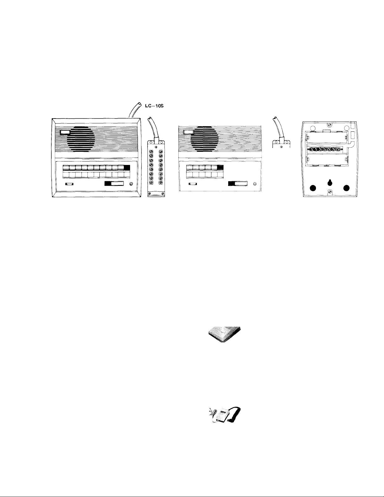
LC-10S
MODEL LC—3S (three call master)
MODEL LC—5S (five call master)
MODEL LC—10S (ten call master)
-INSTRUCTIONS-
LC-3S
T ¿¿/null (,/32 t
Speaker/Microphone
©
Terminal cord
©
Volume control
©
Name plate
©
Signal lamp
©
Selector button
©
Privacy button
©
OFF button
Speaker/Microphone
Talk button
@ ON lamp
(5) Volume control
0
Talk button
©
OFF button
©
Occupied lamp
©
ON lamp
Terminal box
©
Battery box cover
©
®á)¿®
,©
© Name plate
Selector button
Signal lamp
Privacy button
Occupied lamp
Battery box and connecting terminals
1 -
Page 2

SPECIFICATIONS:
* Power source:
DC 6 V. Use PS—2S (CS—12A in North America) power supply per system. If one master
only is used in a system which includes several sub stations, power supply PS—3 (CS—6A in
North America) may be used; or, units may be powered by 4 standard “D” batteries placed
Master Station:
* Current consumption:
* Output:
in each LC—5S or LC—lOS, and 4 standard “C” batteries placed in each LC—3S.
160 mA plus N X 40 mA for an entire system. (N shows number of master stations.)
LC-3S 220 mw, 20i2
LC-5S and LC-1 OS 400 mw, 20D.
* Master station calling:
* Wiring:
Push button station selection. Occupied and on lamps indicate when the system is in use.
Up to 16 conductor cable may be required. Please refer to the instructions and wiring diagrams
to design a system that meets your requirements.
FEATURES:
* Highest manufacturing standard ensures outstanding reliability with trouble free operation.
* Single channel system.
* Hands free remote reply; a call received at an open voice station — if no privacy is required
can be answered from any-
where in a room without touching the instrument (range approximately 20 feet).
“Privacy” button; no monitoring or “eavesdropping” is possible on a station in privacy switch position. A call can still be
received and answered upon unlocking of the privacy button.
A wide choice of substations; seven substations are available to meet individual requirements.
Designed for either desk or wall mounting.
Simple push button operation with volume control for fingertip adjustment.
Excellent voice fidelity due to well engineered and perfectly matched amplifiers.
Master-to-master call by tone or voice direct (LC—3S voice only).
Master receives call from substation by tone and lamp annunciation.
INSTALLATION
Do not attempt to install your intercom system until you have read and thoroughly understood the installation
procedure. Aiphone’s warranty is void if system is installed in a manner other than described in this manual.
WIRING
Lay out your system in advance. Determine the exact location of each station. Make yourself a sketch showing
the number of wires required from each station.
WIRING REQUIRED
LC—lOS — 16 conductors maximum.
LC—5S — 11 conductors maximum.
LC—3S — 7 conductors maximum.
V—A — 2 conductors from V—A to selected master.
V—B — 2 conductors from V—B to selected master.
V—AN — 2 conductors from V—AN to selected master.
V—L — 2 conductors from V—L to selected master.
V—A2 — 3 conductors required; one common and one to each of two selected masters.
V—A4 — 5 conductors required; one common and one to each of four selected masters.
Refer to the chart below and select the proper wire gauge to meet your requirements.
AWG WIRE SIZE
DISTANCE
DIAMETER OF WIRE
DISTANCE
24 AWG
400'
0.5 mm
120 m
22 AWG
650'
0.65 mm
200 m
20 AWG
1000'
0.8 mm
300 m
18 AWG
1600'
1.0 mm
400 m
Page 3
All masters included in your system should be connected and tested before beginning substation installation.) A space
is provided at the left of the all master diagram (on page 4 and 5 of this manual) to write in your color code. Note the posi
tion of the C terminal at each master station. Be sure you wire each station correctly.
lines at a convenient location and that a test be made for calling and talking between each station. (If batteries are used,
insert batteries.) As each additional station is installed re-test between each station. Unplug power supply while making
wiring connections.
ACTUAL LC-S MASTER STATION TERMINAL LOCATIONS:
INSTALLATION FOR WALL MOUNTING.
Begin your installation with master station no. 1. (Master stations should be designated no. 1, no. 2, no. 3, etc.
After installing your second station we recommend that the power supply be connected to the + and — terminal
LC-5S
LC-3S
proper location. Master stations and substations (except V—B) have slots, allowing the station to easily drop over the
screws protruding from the wall.
EQUIPMENT AVAILABLE FOR USE WITH YOUR LC-S LOUD SPEAKER INTERCOM SYSTEM
Your LC—S system is shipped complete with screws for wall mounting. Templates are also provided for easy
II
LC—3S: 3 call master.
LC—5S; 5 call master.
LC—lOS: 10 call master.
V—A: Standard substation places to and re
ceives calls from one master.
V—B: Surface or semi-flush weather resis
tant substation. Places to and receives calls
from one master.
V—AN: Privacy substation. With the »“pri
vacy” button in the depressed position no
voice transmission from this substation is
possible, thus eliminating ‘eavesdropping’
from the master station. This substation
places to and receives a.call from one master.
•f" >
V—L: Memory call substation. .A call to
a master station from this substation will be
indicated by a sound signal and in addition
by a lamp at the master station, both of
which stay on at the master station until the
master station answers. This substation
places to and receives a call from one master.
V—A2: This substation places to and re
ceives calls from two masters.
V—A4: This substation places to and re
receives calls from four masters.
PS—3: Power supply. For a system con
sisting of one master and several sub stations.
Switch must be set at 6 volt.
CS-6A: UNDERWRITERS’ LABORATO
RIES INC. LISTED power supply. For a
system consisting of one master and several
sub stations. Switch must be set at 6V.
(Available only in N. America)
PS—2S: Power supply. One required per
system. Switch must be set at 6 volt.
CS—12A: CSA Listed power supply. One
required per system. Switch must be set at
6V. (Available only in N. America)
3 -
Page 4
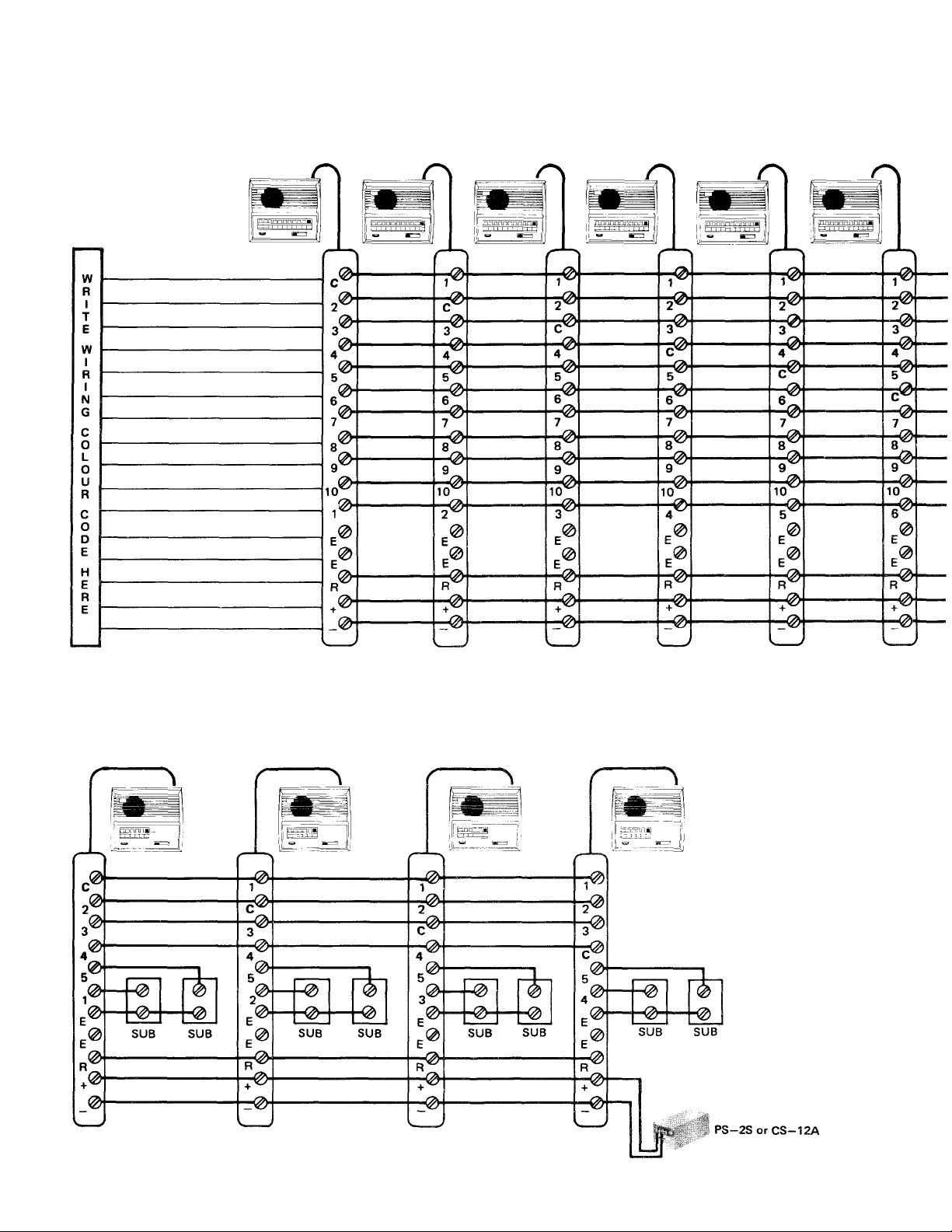
LC-IOS ALL MASTER SYSTEI
If batteries are used in place of central power supply +hen
LC-5S OR LC-IOS WITH SUBSTATIONS
In the above example: (using LC-SS) all master stations can communicate with each other.
Substations may call connected master only if the system is not occupied with another conversation.
Page 5
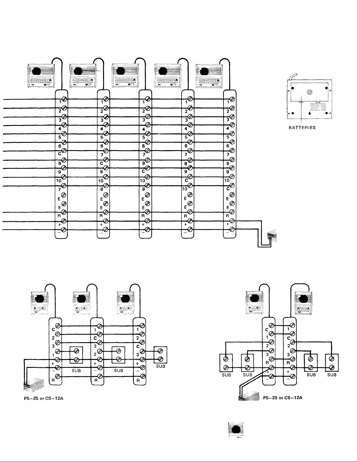
USING CS-12A POWER SUPPLY
> no need to ran wire or make connections to + and — terminals.
LOCATION
LC-3S WITH SUBSTATIONS V-A, V-B, V-L, OR V-AN
PS-2S or CS-12A
SUBSTATIONS V-A
V-B
i
V-L i[ OR V-AN
- 5 -
Page 6
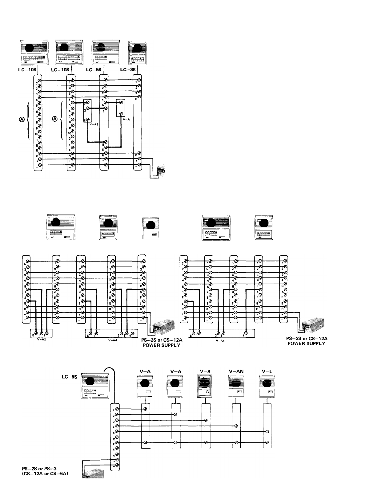
INTERMIXED MASTER STATIONS AND SUBSTATIONS
® These terminals are available for connection to other
subs or masters.
Equipment available for use with an LC—S system can
be intermixed to provide a communications network to meet
your requirements. With proper pre-installation planning,
your LC—S system can become one of the most useful and ver
satile intercom networks available.
PS-2S orCS-12A
POWER SUPPLY
LC-5S SYSTEM WITH V-A2 AND V-A4 SUBSTATIONS
LC-5S
LC-5S
LC-5S LC-5S
V-A4
V-A2
LC-5S LC-5S LC-5S LC-5S LC-5S LC-5S LC-5S
LC-S SYSTEM WITH ONE MASTER AND FIVE SUBS
LC-5S SYSTEM WITH V-A4 SUBSTATION
LC-5S
V-A4
Page 7
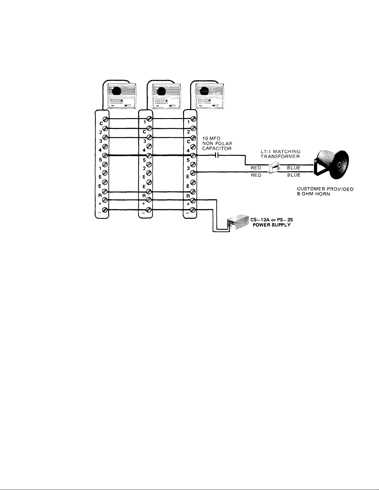
LC-S SYSTEM WITH TALKBACK PAGING HORN
Your LC-S system can not be connected to a standard paging system. In adition your LC-S system was not
designed to incorporate talkback paging horn substations. However, a talkback paging horn may be added to your system
as shown below. You must keep in mind that the LC—3S has an output of 220 mw, and the LC—5S and LC—lOS has an
output of 400 mw.
LT-1 matching transformer is designed for using a standard 8 ohm horn in place of a substation.
15 MFD non-polarized capacitor must be installed between number terminal on master and a red lead of LT-1.
MASTER STATION LC-IOS AND LC-5S OPERATION
Placing a call:
1. Make sure occupied light is not on. (If occupied light is on, then system is in use and you
must wait until the light goes out before placing your call).
2. Depress the selector button of the desired station.
3. To call by tone, momentarily depress both private and talk buttons.
4. To call by voice, depress talk button and speak.
5. To listen, release talk button.
6. Upon completing conversation, depress OFF button.
NOTE: LC—S master station OFF button, when depressed, puts station in standby position as
well as off position. OFF button MUST BE DEPRESSED on all master stations except
station initiating a call or system will not work.
MASTER STATION RECEIVING
1. Receiving a call from another master:
a. Unless privacy switch is in depressed position, no action required and communication
is hands free.
b. With privacy switch in depressed position, release same by momentarily depressing
talk button, then resuming hands free operation as above.
NOTE: There is no lamp annunciation between master stations.
2. Receiving a call from a substation;
a. Substation call is announced by tone and lamp annunciation.
b. Depress the selector switch beneath the lighted indicator lamp.
c. To talk, depress talk button. Release to listen.
d. Upon completing conversation, depress OFF button.
- 7 -
Page 8

MASTER STATION LC-3S OPERATION
BUT FOR THE FOLLOWING TWO EXCEPTIONS, operation of LC-3S master station is
exactly the same as the LC—5S and LC—IOS;
1. Calling by ‘tone’ is not available on the LC—3S.
2. To release LC—3S from privacy position, depress OFF button.
SUBSTATION OPERATING INSTRUCTIONS
V-A
Calling and talking
1. Depress momentarily call button. You will hear a call tone. Wait for master to answer.
After master replies, communication from V—A is hands free.
2. If no call tone is heard when V—A call button is depressed, the system is occupied with
another conversation. Wait a few moments, then place call again.
V-B
Same as V—A.
V-A2
Same as V—A except two buttons allowing calling and talking to two masters.
V
V-L
Same as V—A except memory relay maintains calling tone at master. If master does not
answer, call may be cancelled by depressing red OFF button.
V-AN
Calling and talking operation same as V—A.
V-AN has privacy switch which allows a call to be received from master but prevents sound
from going back to master. To place V—AN in privacy position, depress OFF button. To
release privacy switch for conversation, momentarily depress call button.
----
V-A4
^ Depress selector button corresponding to the master you wish to call, then call button.
* Calling and talking same as V—A. At conclusion of conversation, depress OFF button.
NOTE: OFF button on V-A4 must be in depressed position when sub is not in use.
* Your Aiphone intercom stations may be cleaned with a soft cloth dampened with household cleanser, such as Mr. Clean,
or Fantastik.
We at AIPHONE are proud of our products. Our designers and engineers strive to bring you the finest in communi
cation equipment. Each item has been carefully tested and inspected before leaving our factory. Properly installed and used,
your Aiplione intercom system should give years of trouble-free service.
We are pleased to offer the following warranty;
Ml
Aiphone warrants its products to be free from defects of material and workmanship under normal
use and service for a period of one after delivery to the ultimate user and will repair free of
charge or replace at no charge, should it become defective upon which examination shall disclose
to be defective and under warranty. Aiphone reserves unto itself the sole right to make the final
decision whether there Is a defect in materials and 'or workmanship; and whether or not the prod
uct is within the warranty.
This warranty shall not apply to any Aiphone product which has been subject to misuse, neglect,
accident, or to use In violation of instructions furnished, nor extended to units which have been
repaired or altered outside of the factory.
This warranty does not cover batteries or damage caused by batteries used in connection with the
product.
This warranty covers bench repairs only, and any repairs must be made at the shop or place des
ignated in writing by Aiphone. Aiphone will not be responsible for any costs incurred involving on
site service calls.
WARRANTY
Aiphone Co., Ltd., Nagoya, Japan
Aiphone U.S.A., Inc., Bellevue, Washington
LC-SI-0278(G)
ALL OVER THE WORLD AIPHONE
PRINTED IN JAPAN
 Loading...