

Page 1
IS-SS-2RA
Stainless Steel Flush Mount Door Station with
Standard & Emergency Call Buttons
-INSTRUCTIONS-
The IS-SS-2RA is a stainless steel ush mount door station with standard and emergency call
buttons. The unit is equipped with ADA compliant lettering and Braille signage for both the
standard and emergency buttons. A call status indicator is included to meet ADA rescue assistance
requirements. The IS-SS-2RA must be programmed as a video door station and must connect to the
IS-CCU or IS-SCU control units.
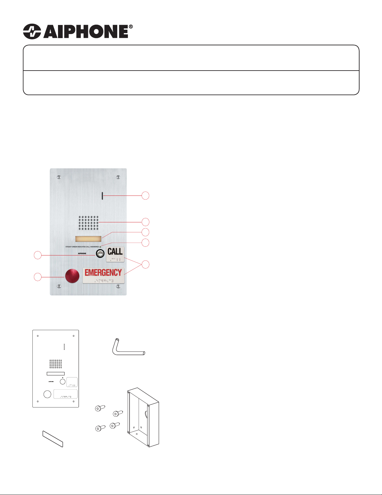
IS-SS-2RA NAMES & FUNCTIONS:
1. Microphone 5. Signage with Braille
1
2
3
4
2. Speaker 6. Call button
3. Name Placard 7. Emergency button
4. Call status indicator
FEATURES:
6
7
PACKAGE CONTENTS:
STEADY GREEN INDICATES CALL ANSWERED
IS-SS-2RA
Vandal-resistant Door Station
Blank name
placard
CALL
EMERGENCY
5
Security Driver
Semi-ush backbox &
tamper-resistant screws
• Audio communication with calling area
• Two call buttons: Standard and Emergency
• ADA compliant lettering and Braille signage
• LED call status indicator
• CCTV input (Analog NTSC 1Vpp)
• Red mushroom button for emergency call
• Two programmable relay outputs for activation
of external systems/devices
• Name placard
• Stainless steel faceplate with tamper resistant
screws
INSTALLATION:
• For ush mounting, cut a hole in the wall and
use supplied back box.
Box dimensions are:
11-1/16” H x 5-7/8” W x 1-3/4” D
• For surface mounting, use the SBX-ISDVFRA
surface mount box. This box can mount to a
standard 1-gang box or to any at surface.
Pg.1
Page 2
WIRING DIAGRAM:
OFF ON
NO
NO
C
NC
C
NC
1 2 3 4
IS-MV
IS-SS-2RA
NO
COM
NC
OFF ON
1 23 4
NO
C
NC
NO
C
NC
Board on back of unit
See wiring below
N/O Dry Contact
0.5 Amp
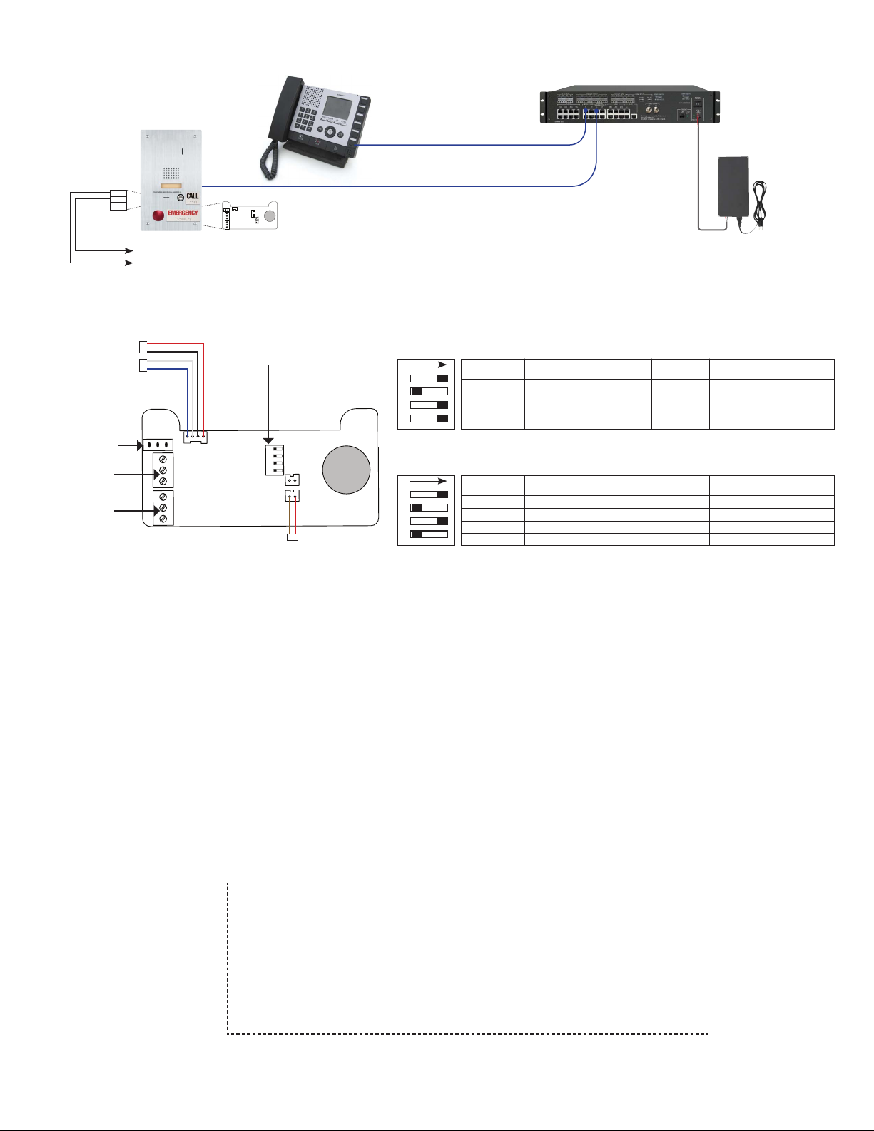
RELAY BOARD WIRING AND SETTINGS:
CCTV Input
CCTV Output
*75Ω termination
for CCTV output
Relay 1 Output
N/O, COM, N/C
Relay 2 Output
N/O, COM, N/C
* Unit is shipped with the pin connector set to the ON
position. Change pin connector to the OFF position to
loop the video signal from the CCTV output.
Conguration Switch
See Settings to right
**Relay 2 External Reset
Connect to N/O dry switch
CAT-5e
CAT-5e
* Connect to the IS-CCU or IS-SCU and program
as a video door station, even if no CCTV camera
is connected. If a CCTV camera is not connected,
the video screen on the IS-MV will illuminate during
communication with station. This is not a malfunction.
Aiphone recommends the IS-SS-2RA-R station be
used if no CCTV camera input is required.
Default Conguration when shipped
Relay 1 triggers on normal call, emergency call, and communication. Relay 1 remains on during communication.
Relay 2 triggers on emergency call and remains on during communication.
1 2 3 4
ON
Trigger Source RY1 Triggered?
Normal Call
Emergency Call
Talking
Door Release
YES
YES
YES YES
NO N/A
Optional Conguration
Relay 1 triggers on normal call, emergency call, and communication. Relay 1 remains on during communication.
Relay 2 triggers on an emergency call and remains on during communication. Relay 2 requires reset.
1 2 3 4
ON
Trigger Source RY1 Triggered?
Normal Call
Emergency Call
Talking
Door Release
YES
YES
YES
NO N/A
Contact Technical Support if additional switch congurations
are required.
IS-CCU
*
RY1 Remains ON
During Talking?
YES
YES
RY1 Remains ON
During Talking?
YES
YES
YES
IS-PU-UL
RY2 Triggered?
RY2 Triggered?
RY2 Remains ON
During Talking?
NO
YES YES NO
NO
NO
NO N/A
YES YES
NO
NO
N/A
N/A
N/A
RY2 Remains ON
During Talking?
N/A
N/A
N/A
RY2 Requires
Reset?
N/A
N/A
N/A
RY2 Requires
Reset?
YES**
N/A
N/A
SPECIFICATIONS:
Terminations: RJ45 jack for audio/video
Screw terminals for door release and relay outputs
Relay rating: 24V AC/DC 0.5A on Door station, 24V AC/DC 1.0A on relay board
Camera Input: Analog NTSC 1Vpp
Operating Temp: 14° ~ 140°F / -10° ~ 60°C
Wiring Distance: 980’ with Cat5e/6 cable
Dimensions: 11-3/4” H x 7” W
w/SBX-ISDVFRA: 11-11/16” H x 7-1/16” W x 2-13/16” D (top), 1-13/16” D (bottom)
FCC WARNING:
This device complies with Part 15 of the FCC rules.
Operation is subject to the following two conditions:
(1) This device may not cause harmful interference.
(2) This device must accept any interference that may cause undesired operation.
• For proper regulatory compliance, the drain wire should be disconnected at the power
supply end of the cable.
• Changes or modications not expressly approved by the party responsible for
compliance could void the user’s authority to operate the equipment.
Aiphone Corporation
1700 130th AVE NE * Bellevue, WA 98005
Ph: (800) 692-0200 * Fax: (425) 455-0071
TOLL FREE TECHNICAL SUPPORT:
(800) 692-0200
E-MAIL: [email protected]
Pg. 2
IS-SS-2RA Instr.
1011JD
 Loading...