

Page 1
IS SERIES
Commercial & Security Video Intercom system
Local System
SETTING MANUAL
Thank you for selecting Aiphone for your communication and security needs. Please read this manual and the separate
“OPERATION MANUAL” carefully before setting and using this system.
*
Refer to the provided “INSTALLATION MANUAL” for complete information regarding this system.
IMPORTANT
Please read and understand the system setting procedures before beginning the setup process.
Please note that images and illustrations depicted in this manual may differ from the actual ones.
Page 2

CONTENTS
ABOUT THIS MANUAL ................... 3
PURPOSE OF THE SYSTEM
SETTINGS ........................................ 3
SETTING LIST ................................. 4
STARTING UP THE SYSTEM .......... 9
System requirements for PC ............. 9
Starting up the system ....................... 9
Setting the system confi guration
[System confi guration] ....................10
MAKING THE SYSTEM
SETTINGS ...................................... 11
The basic setting procedure ...............11
Settings under
[SYSTEM INSTALLATION MENU] ........ 12
Making network settings
[Network setting] .............................. 12
Setting the administrator ID and
password [Administrator setting] ...13
Registering areas [System setting –
Area registration] (Required) ........... 13
Registering zones [System setting –
Zone registration] ............................14
Registering control units
[System setting – Control
units composition] ...........................14
Registering stations and PA outputs
[System setting –
Registering stations] ........................ 15
Setting time and date
[Time and date setting] .................... 19
Settings under
[OPTIONAL FUNCTION MENU] ...........20
Registering sound fi les for chime
[Chime setting – Registering
sound source] ................................... 20
Registering sound sequences
[Chime setting – Registering
sound sequences] ............................20
Registering daily chime schedule
[Chime setting – Registering
daily chime schedule] ...................... 21
Setting chime schedule
[Chime setting –
Chime schedule setting] ..................21
Registering daily transfer schedule
[Transfer setting – Registering
daily transfer schedule] ................... 22
Setting transfer schedule
[Transfer setting –
Transfer schedule setting] ............... 23
Setting the timer [Timer setting]
Settings under
[UPDATING SYSTEM SETTINGS] ........25
Updating the system
[Updating the system] ...................... 25
Downloading setting data onto
the PC [Downloading setting data]
Uploading setting data
[Uploading setting data] ..................25
.....24
..25
Making detailed settings to stations
and control units [System setting –
Advanced station settings] .............. 16
Basic setting procedure ..........................16
Making detailed settings to door
stations or room sub stations ................16
Making detailed settings to master
stations ..................................................17
Making detailed settings to the central
control unit, add-on control unit(s) or
room sub control unit(s) ........................18
Registering stations and PA outputs
to zones
[System setting – Zone setting] ...... 19
2
MAINTENANCE ............................. 26
Initializing the system
[Initialization] ....................................26
Downloading system log
[System log] ......................................26
Updating the fi rmware
[Firmware update] ............................26
Downloading updated fi rmware data
■
Referring to the troubleshooting
guide [Troubleshooting] .................. 26
Registering your system
[Registration] ....................................26
...26
Page 3

ABOUT THIS MANUAL
The IS system provides various manuals to meet various system planning and work processes. Use the manuals necessary for your
system.
Manual confi gurations
The following manuals are provided for a local system. Read all the manuals for installing, setting up, and using a local system, or
provide the manuals to the persons working with the system.
* The INSTALLATION MANUAL includes the contents for a standard (IP) system.
INSTALLATION MANUAL (A booklet included with the central control unit)
Used for installing and connecting control units, stations and power supply unit. (For an installer or serviceman)
SETTING MANUAL (This manual on the CD-ROM included with the central control unit)
This manual describes how to make the system settings and system maintenance. (For an installer or serviceman)
OPERATION MANUAL (An electronic manual on the CD-ROM included with the central control unit)
Information for using the system for calling, communicating, paging, monitoring, etc. (For users of the system)
PURPOSE OF THE SYSTEM SETTINGS
After the installation and connections of all the components are completed, confi gure the system settings based on how your system
is planned to be used. System settings must be completed before the system will operate.
CAUTION:
Make the settings correctly. If the settings are not made correctly, the system will not function as planned.
GETTING STARTED USING THE SYSTEM APPENDIX
SETTING THE SYSTEM
NOTE:
This manual is for setting a local system. To make settings for a standard (IP) system using an IP network, read
the SETTING MANUAL for the standard (IP) system.
3
Page 4
SETTING LIST
The following is the list of system settings you can make via the web browser. The titles or items in shaded cells are required.
NOTE:
The following list is a brief overview of the setting items available in the system settings on a PC. The descriptions, and the style and order of
descriptions do not necessarily equate with the actual displays.
Title Sub title Item Sub item Setting range Default
(On the login
window)
SYSTEM INSTALLATION MENU
System
confi guration
Network setting - IP version - IPv4/IPv6 IPv4
Administrator
setting
System setting Area registration Area name - Up to 24 alphanumeric characters
-
(Language) - English/French/German/Spanish
/Dutch/Italian/Japanese
- - - Local system/Standard system
(IP system)
(Select the network
setting method.)
- IPv4 DHCP/Static IP Address DHCP
IPv6 Stateless Address
Autoconfi guration
/Static IP Address
Static IP Address Static IP Address (required when
[Static IP Address] is selected)
Subnet Mask (required when
[Static IP Address] is selected)
IPv4 0 – 255 (for each fi eld) 192.168.0.30
IPv6 0::1 – ffff:ffff:ffff:ffff:ffff:ffff:ffff:ffff fdc2::5000
IPv4 0 – 255 (for each fi eld) 255.255.255.0
IPv6 (Unmodifi able)
Default Gateway IPv4 0 – 255 (for each fi eld) -
IPv6 0::1 – ffff:ffff:ffff:ffff:ffff:ffff:ffff:ffff -
Primary DNS Server IPv4 0 – 255 (for each fi eld) -
IPv6 0::1 – ffff:ffff:ffff:ffff:ffff:ffff:ffff:ffff -
Secondary DNS Server IPv4 0 – 255 (for each fi eld) -
IPv6 0::1 – ffff:ffff:ffff:ffff:ffff:ffff:ffff:ffff -
MAC address - (Unmodifi able)
Unit name - Up to 24 alphanumeric characters
(except accent marks, umlaut marks,
etc.)
Web port - 443 (Unmodifi able)
- New administrator ID - Up to 16 alphanumeric characters Current Password - Up to 16 alphanumeric characters - (aiphone)
New Password - Up to 16 alphanumeric characters New Password
- Up to 16 alphanumeric characters -
(Re-type)
(for up to 99 areas)
Zone registration Zone name - Up to 24 alphanumeric characters
(for up to 99 zones)
Control units
composition
Room sub control
unit 1 to 4,
- Connected/Not connected Not connected
Add-on control unit 1
to 2
Registering
Area (stations only) - (Area) 01 to 99 (Some are set by
stations
Station number
(stations only)
- 001 to 999
0001 to 9999
00001 to 99999
Station name
- Up to 24 alphanumeric characters (Some are set by
(for stations)
Station name
- Up to 24 alphanumeric characters (Some are set by
(for PA output)
(Required when
an external unit is
connected to the
corresponding PA
output terminals)
Station type
- (Select from the registered ones.) (Depends on the
(sub stations only)
English
Local system
Stateless
Address
Autoconfi guration
-
(Some are set by
default.)*
(Some are set by
default.)*
default.)*
(Some are set by
default.)*
default.)*
default.)*
1
1
1
1
1
1
control unit.)
*1: Confi rm the default settings in the corresponding window.
4
Page 5
Title Sub title Item Sub item Setting range Default
System setting Advanced station
settings
Video door station
/Audio door station
/Room sub station
Call priority Normal/Priority/Urgent Normal
Called stations (Set up to 20 master stations from
Called
stations
the registered ones.)
Contact type Normally open (NO)
/Normally closed (NC)
(Some are set by
default.)*
1
Normally open
(NO)
GETTING STARTED USING THE SYSTEM APPENDIX
Call priority/Answering
the page
Answering the page
/Call (Normal/Priority/Urgent)
Contact input
(room sub stations only)
Transmit volume boost
at PTT
Camera zoom image
ON/OFF
(ON: approx. +6dB up)
0 (wide)/1/2/3/4/5/6/7/8/9 (zoom) 5 (Center)
preset (video door
stations only)
Call acknowledge tone
Other
on/off
Backlight adjustment
ON/OFF ON
Exposure +/Exposure - Exposure +
(video door stations only)
Speaker
(room sub stations only)
Built-in speaker
/External speaker
Master station Stations to be scan monitored (Select up to 20 sub stations from
the registered ones.)
Master station function:
ON/OFF ON
paging, chime, monitor,
door release, and remote
Other
site call
Central control unit
(Contact input) S1 to S4 S1
Contact type
Normally open (NO)
/Normally closed (NC)
Trigger condition None/Broadcast chime/Stop chime None
Sound source
(Only when "Broadcast
chime" is selected at
"Trigger condition")
Internal sound source (Select a
sound fi le or sequence name from
the registered ones in the list.)
/External sound source (Select
either External sound source 1 or 2.)
Chime priority
Contact input
(Only when "Broadcast
Normal/Priority/Urgent Normal
chime" is selected for
"Trigger condition")
Zone name
(Select from the registered ones.) -
(Only when "Broadcast
chime" is selected at
"Trigger condition")
(Contact output terminal)
Contact type
L1 to L8 L1
Normally open (NO)
/Normally closed (NC)
Trigger condition None/Calling notice/Door release
/External sound source/PA output
Calling notice
(Only when "Calling
notice" is selected at
Normal: OFF/ON
Priority: OFF/ON
Urgent: OFF/ON
"Trigger condition")
Door release
(Only when "Door
release" is selected at
"Trigger condition")
Contact output
External sound source
(Only when "External
(Select from the sub stations
registered and set for the central
control unit.)
External sound source 1
/External sound source 2
sound source" is
selected at "Trigger
condition")
PA output
PA output 1 to 4 -
(Only when "PA output"
is selected at "Trigger
condition")
Urgent
OFF
Built-in speaker
(Some are set by
default.)*
1
Normally open
(NO)
-
Normally open
(NO)
None
Normal: OFF
Priority: OFF
Urgent: OFF
-
-
SETTING THE SYSTEM
*1: Confi rm the default settings in the corresponding window.
5
Page 6
Title Sub title Item Sub item Setting range Default
System setting Advanced station
settings
Room sub
control unit/
Add-on control
unit
(Contact output terminal) L1 to L4 L1
Contact type
Normally open (NO)/Normally closed
(NC)
Trigger condition None/Calling notice/Door release/PA
output
Calling notice
(Only when "Calling
notice" is selected at
Normal: OFF/ON
Priority: OFF/ON
Urgent: OFF/ON
"Trigger condition")
Door release
(Only when "Door
Contact output
release" is selected at
(Select from the sub stations
registered and set for each control
unit.)
"Trigger condition")
PA output
PA output 1 to 4 -
(Only when "PA output"
is selected at "Trigger
condition")
Zone setting Zone number - (Select from the registered ones.) (Some are set by
Stations - (Select from the list.) (Some are set by
PA output - (Select from the list.) (Some are set by
Time and date
setting
- Set current time Manual setting Year: 2009 to 2099
Month: 1 to 12
Day: 1 to 31
Hour: 0 to 23
Minute: 0 to 59
Second: 0 to 59
Synchronized with PC - -
NTP Synchronized with NTP server ON/OFF OFF
NTP server*
NTP port number*
(UTC time zone*
Hour difference*
(UTC time zone*
Minute difference*
Synchronize interval*
Daylight savings time - ON/OFF OFF
Starts*
2
2
2
)
2
2
)
2
2
3
Month JAN to DEC (M) JAN
IP address or domain name 1 to 65535 123
-12 to +13 (h) 0
-45/-30/0/+30/+45 (m) 0
1 to 240 (h) 24 (h)
Day (Week) 1st to 4th (W)/The last 1st
(Day) Sunday to Saturday Sunday
Hour (Hour) 0 to 23 (h) -
(Minute) 0 to 59 (m) -
Ends*
3
Month JAN to DEC (M) JAN
Day (Week) 1st to 4th (W)/The last 1st
(Day) Sunday to Saturday Sunday
Hour (Hour) 0 to 23 (h) -
(Minute) 0 to 59 (m) Hour difference*
Minute difference*
3
3
0 to 12 (h) 1
0/30/45 (m) 0
Normally open
(NO)
None
Normal: OFF
Priority: OFF
Urgent: OFF
-
default.)*
default.)*
default.)*
1
1
1
(Internal time of
the central control
unit)
*1: Confi rm the default settings in the corresponding window.
2
: Available only when [Synchronized with NTP server] is set to ON.
*
3
*
: Available only when [Daylight savings time] is set to ON.
6
Page 7

Title Sub title Item Sub item Setting range Default
OPTIONAL FUNCTION MENU
Chime setting Registering sound
source
Registering sound
sequences
Registering daily
chime schedule
Chime schedule
setting
Transfer setting Registering daily
transfer schedule
Transfer schedule
setting
(Sound fi le) - SF1 to SF15 (3MB in total, 2MB/fi le) -
Sound number - SS1 to SS20 SS1
Sound sequence
name
Step - 1 to 10 1
Sound source Sound fi le (Select from the registered ones.) -
Schedule number - DS1 to DS10 DS1
Schedule name - Up to 24 alphanumeric characters Chime time - Hour: 0 to 23
Sound source - Sound fi le (Select from the
Zone number - (Select from the registered ones.) Chime priority - Normal/Priority/Urgent Normal
Weekly schedule (Repeat setting) Every week/Every other week Every week
Individual schedule (Date) From the current day to 1 year
Schedule download - (Download the chime (and transfer)
Schedule number - DT1/DT2 DT1
Schedule name - Up to 24 alphanumeric characters Call transfer time - Hour: 0 to 23
Weekly schedule (Repeat setting) Every week/Every other week Every week
Individual schedule (Date) From the current day to 1 year
- Up to 24 alphanumeric characters -
Repeat times 1 to 10 1
Minute: 0 to 59
Second: 0 to 59
registered ones.)
/Sound sequence (Select from the
registered ones.)
/External sound source (1 or 2)
Schedule start date From the current day to 1 year
ahead
Schedule end date From the start day to 1 year ahead (Chime schedule) None/DS1 to DS10 (for each day of
the week)
ahead
Daily chime schedule (Select from the registered ones.) None
Chime time Hour: 0 to 23
Minute: 0 to 59
Second: 0 to 59
Sound source Sound fi le (Select from the
registered ones.)
/Sound sequence (Select from the
registered ones.)
/External sound source (1 or 2)
Zone number (Select from the registered ones.) Chime priority Normal/Priority/Urgent Normal
schedule data in CSV format.)
Minute: 0 to 59
(Set to the Start time and End time
individually.)
Schedule start date From the current day to 1 year
ahead
Schedule end date From the start day to 1 year ahead (Transfer schedule) None/DT1/DT2 (for each day of the
week)
ahead
Daily transfer schedule (Select from the registered ones.) None
Call transfer time Hour: 0 to 23
Minute: 0 to 59
(Set to the Start time and End time
individually.)
-
-
-
None
-
-
-
-
-
-
None
-
-
GETTING STARTED USING THE SYSTEM APPENDIX
SETTING THE SYSTEM
7
Page 8
Title Sub title Item Sub item Setting range Default
Timer setting - Call Normal/Priority/Urgent 10 to 600 (sec.), 0 (Unlimited)
Communication In Local (local system only) 30 to 600 (sec.) 60 (sec.)
Paging - 30 to 600 (sec.) 60 (sec.)
Monitor - 10 to 600 (sec.) 60 (sec.)
UPDATING SYSTEM SETTINGS
Updating the
system
Downloading
setting data
Uploading
setting data
--
--
--
Scan monitor:
Switching
Contact output External sound source 1 10 to 300 (sec.) 30 (sec.)
Door release - 0 to 300 (sec.), (0: Released while
- 5 to 60 (sec.) 5 (sec.)
External sound source 2 10 to 300 (sec.) 30 (sec.)
holding the Door release button
pressed.)
-- -
-- -
-- -
Normal: 30 (sec.)
Priority: 90 (sec.)
Urgent: 0
(Unlimited)
10 (sec.)
8
Page 9
STARTING UP THE SYSTEM
Before making the system settings, confi rm that a PC is connected to the central control unit (IS-CCU). The system settings are made
on the PC by accessing the web browser for the settings incorporated with the central control unit (IS-CCU).
NOTE:
When you fi rst access the web browser for the settings, access it by the address (https://192.168.0.30) for IPv4 even though IPv6 is used in your
network.
System requirements for PC
Your PC and operating environment must meet the following system requirements to make the settings.
Network 10BASE-T Ethernet, 100BASE-TX Ethernet
Web browser
Internet Explorer 8 or later, Microsoft Edge 38 or later (with Internet Options
SSL 3.0 enabled)
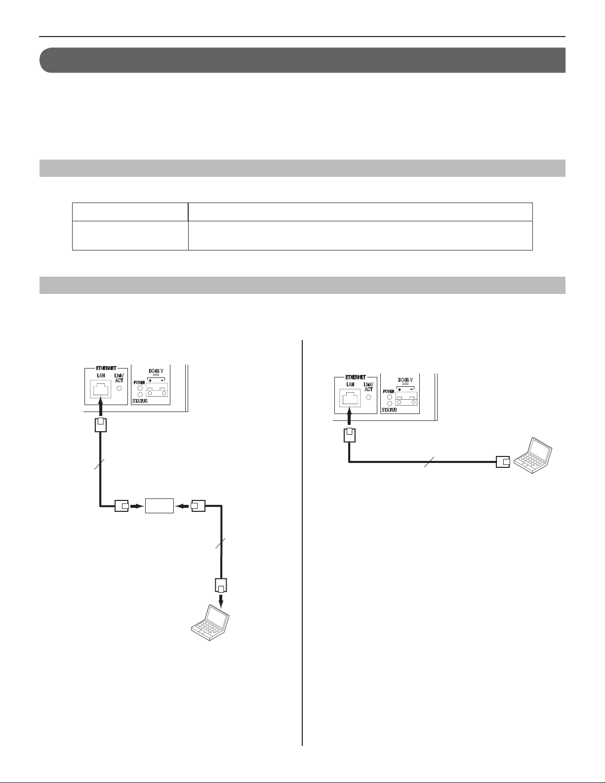
Starting up the system
Connect a PC to the central control unit.
1
[When connecting a PC to the central control unit
via a router]
[When connecting a PC to the central control unit
directly]
GETTING STARTED USING THE SYSTEM APPENDIX
SETTING THE SYSTEM
RJ45
100m (330')
10BASE-T
/100BASE-TX
CAT5e/6
(Straight-through cable)
RJ45
Router
RJ45
100m (330')
10BASE-T
/100BASE-TX
RJ45
PC
CAT5e/6
(Straight-through cable)
NOTES:
•
Select this connection method when you will acquire an IP
address automatically by DHCP.
Do not select this connection method if your router does not
have a DHCP server function.
•
Be sure to connect the CAT5e/6 cable to the LAN ports of both
units.
RJ45
CAT5e/6 (Crossover cable)
100m (330')
10BASE-T/100BASE-TX
RJ45
NOTES:
•
Select this connection method when using a static IP address.
•
When connecting a PC to the central control unit directly, use
an Ethernet crossover cable.
•
The IP address of central control unit is set to (192.168.0.30)
as default. Change the IP address of your PC if needed.
(Continued on next page)
PC
9
Page 10

Press down the "I" side of POWER switch to turn on
2
all the control units in the system.
POWER switch
Press down "I" side to turn on the
•
unit.
Press down "O" side to turn off the
•
unit.
*
Confi rm that the following LEDs
operate as shown below.
Lights up.
Blinks
(When the system settings have
fi nished correctly, this LED turns from
blinking (initializing) to lighting.)
NOTES:
•
Be sure not to log in to the system more than once at the same
time by opening multiple browser windows on the PC.
•
<Only when IPv6 is used>:
When you access the web browser for settings after "IP
version" has been set to "IPv6" at
access it from the assigned IP address or https://[fdc2::5000].
[Network setting]
(
→
P. 12),
Setting the system confi guration
[System confi guration]
After logging in to the system, the [System confi guration]
window appears.
First of all, make the setting on this window before starting the
system settings.
Select your system between “Local system” and
1
“Standard system (IP system)”.
Temporarily stored
Click
2
temporarily. (→P. 11 )
Start the system settings by selecting a setting title in
3
the table of contents on the left side of the window.
to save the setting result
Start up the PC, and then open the browser window.
3
Enter the 4 static IP address (https://192.168.0.30/)
or the IP address assigned by DHCP to access the
web browser for settings.
*
If you do not know your IP address assigned by DHCP,
run “IS_IPSEARCH.exe” from the supplied CD-ROM,
and then search for it.
The login window of the web browser is displayed.
Log in to the system by setting the following items.
5
Select language
•
Select the language for displaying contents on the
setting windows.
ID
•
Enter “aiphone”.
Password
•
Enter “aiphone”.
Login
•
Login
Click
to display the setting window.
Go to the next page.
*
When you log in for the fi rst time, the [
window appears. Register your system as needed when
the IS-CCU is connected to the IP network.
Registration]
10
Page 11

MAKING THE SYSTEM SETTINGS
The basic setting procedure
When you have logged in to the system, the setting window appears. You can make the settings on this window.
*
Make sure to refer to the on-screen instructions and comments displayed on each window when you make the settings.
*
Depending on the PC and its OS or environment, the display may differ.
<Setting window example>
Temporarily stored
Click this to save the current setting results
temporarily.
This temporary storing will not update the system *
with the new setting results. To update the system,
click the title “Updating the system” and follow the
necessary procedure.
Setting contents display area
The setting items of the selected setting title and their
details are displayed here.
Pointing the cursor to an item gives you a supplemental *
explanation with balloon help.
GETTING STARTED USING THE SYSTEM APPENDIX
SETTING THE SYSTEM
Table of contents
The setting titles are listed here. Click the title on
which you want to make the settings to display the
corresponding setting window.
Instructions area
The instructions for settings are displayed
here.
The setting procedure
Click a title in the table of contents on which you wish to make the settings.
1
The setting window of the title is displayed.
Make the settings on the setting items individually.
2
When you have fi nished making the settings on the current window, click
3
Temporarily stored
to save the setting
results temporarily.
*
If you wish to cancel the setting results you have made, click a title in the table of contents or “Refresh” in the web browser
menu. (If you change the current window to another without storing the setting results temporarily, a pop-up window appears
asking if you want to store the results temporarily or not.)
Repeat step 4 1 to 3 to make the settings on the other titles.
To log out of the system, click [* Logout] in the table of contents.
11
Page 12

The following shows the setting procedure for the items of each title.
Refer to “SETTING LIST” (→P. 4-8) for details about the settings. Make the settings by also referring to the on-screen instructions.
Settings under [SYSTEM INSTALLATION MENU]
[Unit name]:
Making network settings [Network setting]
Make the settings for network according to your
requirements.
Click 1 Network setting in the table of contents.
•
Enter a name for this unit. (This name will not be used
when operating the system.)
NOTE:
The items that cannot be changed or selected are grayed out.
Temporarily stored
3
Click
to save the current setting
results temporarily.
*
If you wish to cancel the setting results you have made,
click a title in the table of contents or “Refresh” in the
web browser menu.
Make the settings on the following items displayed in
2
the setting window.
[IP version]:
•
Select either “IPv4” or “IPv6” that is used in your network.
Selecting the network setting method
<When "IP version" is set to "IPv4">
Set a (static) IP address to this unit. Select the method
for acquiring a (static) IP address between [DHCP] and
[Static IP Address].
[DHCP]:
•
Check this when you will acquire an IP address from
DHCP.
*
A DHCP server (or a router) is required to acquire
an IP address from DHCP. A router may not have
the setup function depending on some models. For
information about setting a router, see the instruction
manual for the router.
[Static IP Address]:
•
Check this when you set the static IP address
manually, and then enter the static IP address suitable
for the network you are using, subnet mask, etc.
*
It is required to enter the static IP address and
subnet mask.
<When "IP version" is set to "IPv6">
Set an IP address to this unit. Select either [Stateless
Address Autoconfi guration] or [Static IP Address] for
acquiring an IP address.
[Stateless Address Autoconfi guration]:
•
Check this when an IPv6-supported router can be
connected to this system and you will aquire an IP
address from Stateless Address Autoconfi guration.
*
Select this method when you will acquire an IP
address from a router that supports DHCPv6-PD
only.
*
For information about setting a router, see the
instruction manual for the router.
[Static IP Address]:
•
Check this when you set the static IP address
manually, and then enter the static IP address suitable
for the network you are using, default gateway, etc.
*
It is required to enter the static IP address.
When the settings on this window have fi nished,
4
update the system from [Updating the system].
(→P. 25)
12
Page 13

Setting the administrator ID and password
[Administrator setting]
We recommend that you change the administrator ID and
password from default to unique ones for security purposes.
*
“aiphone” is preset as the default for both ID and password.
Click 1 Administrator setting in the table of contents.
Make the settings on the following items displayed in
2
the setting window.
[New administrator ID]:
•
Enter the new ID.
[Current Password]:
•
Enter the current password.
[New Password]:
•
Enter a new password.
[New Password (Re-type)]:
•
Enter the new password again.
Temporarily stored
Click
3
results temporarily.
*
If you wish to cancel the setting results you have made,
click a title in the table of contents or “Refresh” in the
web browser menu.
to save the current setting
Registering areas
[System setting – Area registration]
Register areas for separating stations in the system. The
number to which a name is entered is registered as an area
number. Up to 99 areas can be registered.
Click 1 Area registration in the table of contents.
Enter an area name in the cell for the area number 01.
2
*
The fi gures under "Number" in the tables means the area
numbers.
Enter area names in the cells for other numbers to
3
register more areas.
Temporarily stored
Click
4
results temporarily.
*
If you wish to cancel the setting results you have made,
click a title in the table of contents or “Refresh” in the
web browser menu.
NOTES:
•
Be sure to register at least one area to the area number 01.
(“Area1” is entered in the cell for the area number 01 as default.)
•
A call number displayed on the master station monitor consists of
an area number plus a station number.
to save the current setting
Required
GETTING STARTED USING THE SYSTEM APPENDIX
SETTING THE SYSTEM
NOTE:
The system administrator must keep the ID and password without
fail. If you forget the ID and password, you must initialize the unit,
thus all the setting contents return to default.
13
Page 14

Registering zones
[System setting – Zone registration]
Registering control units [System setting
– Control units composition]
Register zones for paging (transmitting announcements and
chime). The number to which a name is entered is registered
as a zone number. Up to 99 zones can be registered.
*
Zones are groups of stations designated for paging and
chime paging.
*
Some zones are registered by default. Change them as
needed.
Click 1 Zone registration in the table of contents.
Enter a zone name in the cell for the target zone
2
number.
*
The fi gures under "Number" in the table means the zone
number.
Enter zone names in the cells for other numbers to
3
register more zones.
4
Click
to save the current setting
Temporarily stored
results temporarily.
*
If you wish to cancel the setting results you have made,
click a title in the table of contents or “Refresh” in the
web browser menu.
Register all the control units connected to the central control
unit.
Click 1 Control units composition in the table of
contents.
Click to check the radio button under "Connected" for
2
the unit you will register.
*
Connection check
Click
Connected: yellowish green
Not connected: gray
Shows a port no. of the central control unit to connect with
a room sub control unit or add-on control unit.
to confi rm the connected units.
Shows the ID setting of the room sub control unit or add-
on control unit set by the ID setting switches. (Refer to the
INSTALLATION MANUAL for details.)
Temporarily stored
3
Click
to save the current setting
results temporarily.
*
If you wish to cancel the setting results you have made,
click a title in the table of contents or “Refresh” in the
web browser menu.
14
Page 15

Registering stations and PA outputs
[System setting – Registering stations]
Register all the stations and PA outputs connected in the
system, and set the area, station no., station name (or PA
output name) and type of station (for sub stations: video door/
audio door/room sub stations) to them.
Click 1 Registering stations in the table of contents.
Set the area, station no., station name and type of
2
station (for sub stations) to the target stations, and
enter names to the target PA outputs.
*
Setting the station no. is required.
*
Shows a port no. of the control unit to connect with a
station.
Station number
•
Click to assign sequential numbers to all the checked
stations from top to bottom. The number you enter will
be set as the fi rst number and will be assigned to the top
station of the ones checked. Other checked stations will
be numbered sequentially.
Station name
•
Click to assign the same station (and/or PA output) name
and sequential numbers to all the checked stations (and/
or PA outputs) from the top down. Enter a name only.
Station type
• (sub stations)
Click to set the same station type to all the checked sub
stations.
How to select multiple stations
○ Click to check the stations and PA outputs you will
register.
GETTING STARTED USING THE SYSTEM APPENDIX
SETTING THE SYSTEM
*
It is required to enter a name to the target PA
output when an external unit is connected to the
corresponding PA output terminals.
*
For a cell with the
pull-down menu.
*
Do not set stations with the same number in an area.
NOTE:
The name of a master station displayed on its monitor in standby
mode is up to 16 alphanumeric characters.
mark, select the target one from the
Other buttons
Connection check
•
Click to confi rm the connected units.
Connected: yellowish green
Not connected: gray
Station type error: pink
[Collective setting]:
•
The following buttons are used to make the settings to all
the checked stations at one time.
*
Pressing each button opens another window.
○ By clicking the button for the control unit, all the stations
and PA outputs connected to it are checked or canceled.
○ By clicking the button on the top of the list, you can
check or cancel all the stations and PA outputs on the
list.
Temporarily stored
3
Click
to save the current setting
results temporarily.
*
If you wish to cancel the setting results you have made,
click a title in the table of contents or “Refresh” in the
web browser menu.
NOTE:
Be sure to check all the target stations before using these
buttons.
Area
•
Click to set the same area number to all the checked
stations.
15
Page 16

Making detailed settings to stations and
control units
[System setting – Advanced station settings]
Make detailed settings for the registered stations and control
units. The settings can be made to a station or control unit
individually, or multiple stations of the same type at a time. The
setting items differ from the station or control unit type. First
select a station (or stations) or control unit, and then open the
“Advanced settings” window to make the settings.
Basic setting procedure
Click Advanced station settings in the table of
contents.
Making detailed settings to door
stations or room sub stations
NOTE:
Make the settings to door stations or room sub stations
respectively. You cannot select a video door station, audio door
station and a room sub station at the same time.
The following setting item buttons are displayed in the
“Advanced settings” window.
A
(Room sub stations only)
B
C
Click to check the station(s) or control unit where detailed
settings are to be made.
*
Multiple stations of the same type can be set together.
(Control units should be set respectively.)
*
All stations of the same type can be selected by clicking the
corresponding button under [Select all by type].
Advanced settings
Click
The “Advanced settings” window for the selected station type
or control unit opens.
.
Make the settings in the displayed windows.
For door and room sub stations
The right column of this page
For master stations
P. 17
For control units
P. 18
*
Click one of the buttons
corresponding setting window, and then make the
settings in the displayed window(s). See the detailed
instructions for
*
A
Settings on [Called stations] setting window
Set the master station(s) that is (are) to be called from the
selected station(s).
*
*
Select the “Call priority” from the pull-down menu.
1
Click
2
Close
Click
the previous window.
Up to 20 master stations can be set.
Some master stations are set by default. Change them
as needed.
Reference
A
to close the current window and return to
to open another window, then check
the target master stations, and then click
A
B
or C below.
,
B
and C to open the
,
Close
return to the previous window.
The selected master stations are added and
displayed in the list.
to
When you have fi nished making all the detailed settings:
Temporarily stored
Click
to save the current setting
results temporarily.
*
If you wish to cancel the setting results you have made, click
a title in the table of contents or “Refresh” in the web browser
menu.
16
*
To delete a station (or stations) from the list, check the
target station(s) in the list and click
Delete
Repeat step 3 2 to add more master stations.
4
Click
to close the current window and return to
Close
the previous window.
.
Page 17

B
Settings on [Contact input] window (for room
sub stations only)
Make settings for contact input.
[Contact type]:
•
Select either Normally open (NO) or Normally closed (NC).
[Call priority/Answering the page]:
•
You can select the action of the station when detecting
input between ‘calling with appropriate priority’ and
‘answering the page’.
Select “Normal”, “Priority”, “Urgent” or “Answering the
page”.
Close
•
Click this to close the current window and return to the
previous window.
C
Settings on [Other] window
[Transmit volume boost at PTT]:
•
Select whether to increase the press-to-talk sound
volume transmitted to the stations (ON) or not (OFF).
[Camera zoom image preset] (video door stations
•
only):
Select the default of camera’s Zoom/Wide function at
calling from the 9 zoom positions and "0" (wide) from the
pull-down menu.
[Call acknowledge tone on/off]:
•
Select whether to sound the call acknowledge tone of
door station or room sub station (ON) or not (OFF).
[Backlight adjustment] (video door stations only):
•
Select the method of adjusting the backlight in the
daytime between “Exposure +” and “Exposure –”.
[Speaker] (room sub stations only):
•
Select the speaker to be used between “Built-in speaker”
and “External speaker”.
*
When “External speaker” is selected, no sound will be
output from the built-in speaker.
Close
•
Click this to close the current window and return to the
previous window.
Making detailed settings to master
stations
The following setting item buttons are displayed in the
“Advanced settings” window.
D
E
*
Click either the button
corresponding setting window, and then make the
settings in the displayed window(s). See the detailed
instructions for
*
D
Settings on [Stations to be scan monitored]
Close
Click
the previous window.
to close the current window and return to
window
Set the scan-monitoring target sub station(s).
*
Some sub stations are set by default. Change them as
needed.
*
Up to 20 sub stations can be set.
Reference
1
Click
to open another window, then select
the target stations, and then click
the previous window.
The selected stations are added and displayed in the
list.
*
To delete a station (or stations) from the list, check the
target station(s) in the list and click
Repeat step 2 1 to register more stations.
3
Click
to close the current window and return to
Close
the previous window.
D
or E below.
D
or E to open the
Close
to return to
Delete
.
GETTING STARTED USING THE SYSTEM APPENDIX
SETTING THE SYSTEM
About the priority
When receiving two or more functions (communication,
calling, paging, monitoring, etc.) at the same time,
depending on the priority setting, the order of priority for
them is as follows.
Priority Setting Function
1 (high) [Urgent] Communication, calling,
2 [Priority]
3 [Normal]
4 (low) - Monitoring, scan-monitoring
paging, chime paging
E
Settings on [Other] window
[Master station function: paging, chime, monitor,
•
door release, and remote site call]:
Select whether to enable the following functions of
master station (ON) or not (OFF).
Starting paging
•
Starting chime paging
•
Monitoring/scan-monitoring
•
Releasing door
•
Remote site call
•
Close
•
Click this to close the current window and return to the
previous window.
17
Page 18

Making detailed settings to the central control
unit, add-on control unit(s) or room sub
control unit(s)
NOTE:
Make the settings to the central control unit, add-on control
unit(s) or room sub control unit(s) respectively. You cannot select
multiple control units at the same time.
The following setting item buttons are displayed in the
“Advanced settings” window.
(central control unit only)
F
G
*
Click either the button
corresponding setting window, and then make the
settings in the displayed window(s). See the detailed
instructions for
*
Close
Click
the previous window.
to close the current window and return to
F
F
or G below.
or G to open the
[Sound source]:
•
Select either [Internal sound source] or [External
sound source] as the source of chime. When [Internal
sound source] is selected, select a sound fi le or
sequence from the registered ones in the list.
(You need to register sound fi les and/or sound
sequences in advance. (→P. 20))
When [External sound source] is selected, select
either “External sound source 1” or “External sound
source 2”.
[Chime priority]:
•
Select the priority of chime paging from among
“Normal”, “Priority” and “Urgent”.
[Zone name]:
•
Select the target zone of chime paging from the
registered ones in the list.
Repeat step 4 1 to 3 to make the settings to other
terminals.
5
Click
to close the current window and return to
Close
the previous window.
G
Settings on [Contact output] window
Set the trigger condition to each of the CONTACT OUTPUT
terminals.
Select an output terminal from the pull-down menu.
1
F
Settings on [Contact input] window (for central
control unit only)
Set the input method to each of the CONTACT INPUT
terminals.
Select the input terminal from S1 to S4 from the pull-
1
down menu.
[Contact type]:
2
Select either Normally open (NO) or Normally closed
(NC).
[Trigger condition]:
3
Select [None], [Broadcast chime] or [Stop chime] as
the trigger condition. When an input is detected, the
selected action is triggered.
[None]:
•
None will be triggered if an input is detected.
[Broadcast chime]:
•
Chime paging to the designated zone is triggered if an
input is detected.
[Stop chime]:
•
The currently-transmitted chime is stopped if an input is
detected.
*
Only when [Broadcast chime] is selected, the following
items are valid.
*
Select from L1 to L8 for the central control unit, and
select from L1 to L4 for the add-on control unit and room
sub control unit.
[Contact type]:
2
Select either Normally open (NO) or Normally closed
(NC).
[Trigger condition]:
3
Select the action as the trigger condition from among
the following. When the selected action is detected,
output is triggered.
[None]:
•
No output will be triggered.
[Calling notice]:
•
Set ON or OFF for “Normal”, “Priority” or “Urgent”.
[Door release]:
•
Select one of the registered sub stations in the list
to which an electric door strike is connected. (Click
Reference
[External sound source] (central control unit only):
•
Select either “External sound source 1” or “External
sound source 2” connected to the central control unit.
[PA output]:
•
Select from among “PA output 1” to “PA output 4”
connected to the control unit.
, and then select the target station.)
Repeat step 4 1 to 3 to make the settings to other
terminals.
18
5
Click
to close the current window and return to
Close
the previous window.
Page 19

Registering stations and PA outputs to zones
System setting – Zone setting]
[
Assign stations and PA outputs to the registered zones.
*
Some stations and PA outputs are set by default. Change
them as needed.
Click 1 Zone setting in the table of contents.
Setting time and date
[Time and date setting]
Set the time and date of the system, used for chime schedule
and transfer schedule.
Click 1 Time and date setting in the table of contents.
GETTING STARTED USING THE SYSTEM APPENDIX
Select a zone from the pull-down menu.
2
Reference
3
Click
to display all the stations registered
to the system.
Another window opens and the registered stations are
displayed in the list.
Check to select the target stations.
4
Select stations in the following ways.
Select stations by checking one by one.
•
All stations of the same type can be selected by
•
clicking the corresponding button under [Select all by
type].
By clicking the button for the control unit, all the
•
stations connected to it are checked or canceled.
By clicking the button on the top of the list, all the
•
stations are checked or canceled.
Close
5
Click
after you have fi nished selecting the
stations.
In the previous window, the selection results are displayed
in the list.
*
When canceling a registered station, check the station in
the list, then click
*
Register PA outputs in the same way as the stations.
Temporarily stored
Click
6
.
Delete
to save the current setting
results temporarily.
*
If you wish to cancel the setting results you have made,
click a title in the table of contents or “Refresh” in the
web browser menu.
Set the following settings.
2
[Set current time]
•
Set the current time and date in one of the following
methods.
Input the current time and date manually, and then
•
•
•
*
[NTP (Network Time Protocol)]:
•
Set [Synchronized with NTP server] to ON to set the
current time and date by making it synchronized with NTP
server. Then set the [NTP server] and [NTP port number]
*
•
•
•
*
It is recommended to connect the system with a PC or NTP
server constantly to keep the correct time and date setting
Click
3
Manual setting
click
Synchronized with PC
Click
and date by making it synchronized with the PC.
You can also set the current time and date by
synchronized with NTP server [Synchronized with NTP
server] as shown below.
If there is no power supply to the system for a long
time because of power failure etc., the time and date
setting may be cleared.
[NTP server]:
Enter the IP address or domain name of the NTP
server to be used as the master clock.
[UTC time zone]:
Set the time differences from Coordinated Universal
Time (UTC). Set the [Hour difference] and [Minute
difference] respectively.
[Synchronize interval]:
Set the time data acquisition interval (hour) from the
NTP server, and the interval of synchronization with
the system.
[Daylight savings time]:
Set whether to utilize daylight savings time (ON) or
(OFF). When set to ON, then set the start and end
times (Month, Week of the month, Day of the week,
Hour and Minute), and time differences (Hour and
Minute).
Temporarily stored
Required
.
:
to set the current time
to save the current setting
making it
results temporarily.
*
If you wish to cancel the setting results you have made,
click a title in the table of contents or “Refresh” in the
web browser menu.
NOTE:
When using an NTP server, be sure to enter the data for the NTP
server to be used in
[Network setting]
(
→
P. 12).
SETTING THE SYSTEM
.
.
19
Page 20

Settings under [OPTIONAL FUNCTION MENU]
Registering sound fi les for chime
[Chime setting – Registering sound source]
Register sound data as the source of each chime. Copy MP3format sound fi les onto the PC in advance. (Only MP3 fi les can
be registered in the system.)
* Up to 3MB of the total amount of fi les can be registered.
* Use sound fi les compliant with the specifi cations below.
Sound fi le specifi cations
Item Recommended value
File name Up to 24 alphanumeric characters
File format MP3*
Bit rate 64 kbps
Sampling frequency 44.1 kHz
Channels 1 ch (monaural)
Maximum total data size 3MB in total, 2MB/fi le
1
: MP3-format sound fi les with tags may not be played with this
*
system. Before registering an MP3-format sound fi le, delete the
tag from the fi le.
Click 1 Registering sound source in the table of
contents.
Add
Click
2
Another window opens.
Click
3
Click
4
When uploading the fi le is completed successfully, the
current window closes. In the previous window, the
selection result is displayed in the list.
*
If a small-size sound fi le is registered, a fi le size different
from the actual one may be displayed.
.
Browse...
Upload
and select a sound fi le on the PC.
to save.
Repeat step 5 2 to 4 to register more sound fi les.
*
If you wish to delete a sound fi le, check it in the list, and
then click
Delete
.
1
Registering sound sequences
[Chime setting – Registering sound sequences]
Register sound sequences for chime.
*
Up to 20 sequences can be registered.
Click 1 Registering sound sequences in the table of
contents.
[Sound number]:
2
Select the sound number to register a sound sequence
from the pull-down menu.
[Sound sequence name]:
3
Enter the name of sound sequence.
Add
Click
4
Another window appears.
[Step]:
5
Select an unused step number from the pull-down menu.
*
If the selected step number is already used, it can be set
with a new sound source and the old and subsequent
ones are renumbered with the following numbers.
*
If an unused number exists before the number you
selected, the unused number is re-selected automatically.
*
Up to 10 steps can be used.
[Sound source]:
6
Select a sound fi le from the registered ones and set the
repeating time (from 1 to 10) of the sound.
When you have fi nished the setting on this window,
7
click
In the previous window, the registered sound fi les are
displayed in the list.
Repeat step 8 2 to 7 to register more sound sequences.
Other buttons
Edit
•
If you wish to modify, check the fi le in the list, and then
click
Delete
•
When deleting an added sound fi le, check the fi le in the
list, and then click
Click
9
results temporarily.
*
If you wish to cancel the setting results you have made,
click a title in the table of contents or “Refresh” in the
web browser menu.
to add sound fi les to the sound sequence.
Close
.
.
Edit
.
Delete
Temporarily stored
to save the current setting
20
Page 21

Registering daily chime schedule
[Chime setting – Registering daily chime schedule]
Up to 10 daily schedules can be registered.
Click 1 Registering daily chime schedule in the table
of contents.
Setting chime schedule
[Chime setting – Chime schedule setting]
You can set a weekly chime schedule or individual daily
schedule.
* The settings can be made to 1 year ahead.
Click 1 Chime schedule setting in the table of
contents.
GETTING STARTED USING THE SYSTEM APPENDIX
[Schedule number]:
2
Select the schedule number to register the daily
schedule from the pull-down menu.
[Schedule name]:
3
Enter the name of daily schedule.
Add
Click
4
Another window appears.
[Chime time]:
5
Set the starting time (hour, minute and second).
[Sound source]:
6
Check [Sound fi le], [Sound sequence] or [External
sound source], and select a fi le, sequence or external
sound source from the pull-down menu.
[Zone number]:
7
Select the target zone for transmitting chime from the
pull-down menu.
[Chime priority]:
8
Select the priority of transmitting chime from among
“Normal”, “Priority” or “Urgent” from the pull-down
menu.
When you have fi nished the settings on this screen,
9
click
In the previous window, the added program is displayed in
the list.
to add programs.
Close
.
Make the settings by clicking
2
Individual schedule
respectively to open the corresponding window.
and
Weekly schedule
Schedule download
H
I
J
Individual schedule
*
date is clicked on the calendar.
Make the settings in the displayed window(s).
3
See the detailed instructions for H, I or J on the
right column of this page.
After the setting is fi nished on the corresponding
4
window, click
Calendar and setting status can be checked for the
selected month.
The registered daily chime schedules are identifi ed by
colors and shown on the calendar.
Close
should be clicked after the target
to close the window.
,
SETTING THE SYSTEM
Repeat step 4 to 9 to add more programs.
10
Other buttons
Edit
•
If you wish to modify a program, check the program in
the list, and then click
Delete
•
When deleting a program, check the program in the list,
and then click
Click
11
results temporarily.
*
If you wish to cancel the setting results you have made,
click a title in the table of contents or “Refresh” in the
web browser menu.
Delete
Temporarily stored
Edit
.
to save the current setting
Temporarily stored
Click
5
results temporarily.
*
If you wish to cancel the setting results you have made,
click a title in the table of contents or “Refresh” in the
web browser menu.
When the settings on this window have fi nished, update
6
the system from [Updating the system]. (→P. 25)
to save the current setting
21
Page 22

H
Settings on [Weekly schedule] setting window
Select either [Every week] or [Every other week].
1)
Set the schedule start and end dates.
2)
*
The monthly calendar is displayed by clicking
Refer calendar
end dates.
*
If necessary, you can change the month by clicking
or .
Set one of the registered daily chime schedules or no
3)
schedule to each day of the week. (Select one from the
pull-down menu.)
I
Settings on [Individual schedule] setting window
Set an individual schedule to the target date.
*
[Individual schedule] setting window will not open if you
have not selected the target date on the calendar in the
[Chime schedule setting] window.
If necessary, you can change the date by clicking
1)
repeatedly.
[Daily chime schedule]:
2)
Select one of the registered daily chime schedules or
no schedule (to register a new schedule), from the pulldown menu.
If necessary, modify a registered schedule or register a
3)
new schedule.
To register a new schedule:
•
Add
Click
Another window opens. In this window, you can set
[Chime time], [Sound source], [Zone number] and
[Chime priority].
When the settings have fi nished, click
close this window. In the previous window, the added
program is displayed in the list.
*
Repeat this procedure to add more programs.
To modify a registered schedule:
•
Check the program you wish to modify, and then click
Edit
. Another window opens. Change the settings in
this window.
When fi nished modifying, click
window.
*
You can also modify the registered schedule by
adding new program(s) or deleting program(s). (To
delete, check the target program(s) in the list and
then click
*
When modifi ed, [Daily chime schedule] changes to
“Individual schedule.”
To delete a registered schedule:
•
Select “None” from the pull-down menu of [Daily
chime schedule].
and you can select the start and
.
Close
Delete
.)
Close
to close this
to
or
Registering daily transfer schedule
[Transfer setting – Registering daily
transfer schedule]
You can set the schedule for transferring calls to other master
stations automatically. The schedules registered on this setting
are used when making a transfer setting on a master station.
Up to 2 daily schedules can be registered.
Click 1 Registering daily transfer schedule in the
table of contents.
[Schedule number]:
2
Select the schedule number DT1 or DT2 from the
pull-down menu.
[Schedule name]:
3
Enter the name of daily schedule.
[Call transfer time]:
4
Set the [Start time (hour and minute)] and [End time
(hour and minute)] of transferring.
Temporarily stored
Click
5
results temporarily.
*
If you wish to cancel the setting results you have made,
click a title in the table of contents or “Refresh” in the
web browser menu.
to save the current setting
J
Downloading chime schedule data
You can store the chime schedule setting data in CSV
format onto a PC.
*
The data includes the transfer schedule setting (→P. 23)
data along with the chime schedule setting data.
22
Page 23

Setting transfer schedule
[Transfer setting – Transfer schedule setting]
You can set a weekly transfer schedule and individual daily
schedule.
*
The settings can be made 1 year ahead.
Click 1 Transfer schedule setting in the table of
contents.
Make the settings by clicking
2
Individual schedule
and
respectively to open the
corresponding window.
Individual schedule
*
date is clicked on the calendar.
Make the settings in the displayed window(s).
3
See the detailed instructions for K or L on the
next page.
After the setting is fi nished on the corresponding
4
window, click
Calendar and setting status can be checked for the
selected month.
The registered daily transfer schedules are
identifi ed by colors and shown on the calendar.
should be clicked after the target
Close
to close the window.
Weekly schedule
K
L
K
Settings on [Weekly schedule] setting window
Select either [Every week] or [Every other week].
1)
Set the schedule start and end dates.
2)
*
The monthly calendar is displayed by clicking
Refer calendar
end dates.
*
If necessary, you can change the month by clicking
or .
Set one of the registered daily transfer schedules or no
3)
schedule to each day of the week. (Select one from the
pull-down menu.)
L
Settings on [Individual schedule] setting window
Set an individual schedule to the target date.
*
[Individual schedule] setting window will not open if you
have not selected the target date on the calendar in the
[Transfer schedule setting] window.
If necessary, you can change the date by clicking
1)
repeatedly.
[Daily transfer schedule]:
2)
Select either of the registered daily schedules (DT1 or
DT2) or no schedule from the pull-down menu.
[Call transfer time]:
3)
When “DT1” or “DT2” is selected:
•
The call transfer time is automatically entered.
If necessary, change the [Start time (hour and
minute)] and [End time (hour and minute)] of
transferring manually.
When no schedule is selected:
•
Enter the call transfer time manually.
*
When the time is entered or changed manually, [Daily
transfer schedule] changes to “Individual schedule”.
and you can select the start and
GETTING STARTED USING THE SYSTEM APPENDIX
SETTING THE SYSTEM
or
5
Click
to save the current setting
Temporarily stored
results temporarily.
*
If you wish to cancel the setting results you have made,
click a title in the table of contents or “Refresh” in the
web browser menu.
When the settings on this window have fi nished, update
6
the system from [Updating the system]. (→P. 25)
23
Page 24

Setting the timer [Timer setting]
Set the time for each operation.
Click 1 Timer setting in the table of contents.
Set the time for the following operations respectively.
2
*
The setting range is displayed on the right side of each
input box.
[Call]:
•
Set the duration of call from door stations and room sub
stations to [Normal], [Priority] or [Urgent].
[Communication In Local]:
•
Set the duration of communication between stations.
[Paging]:
•
Set the duration of paging.
[Monitor]:
•
Set the duration of monitoring only one station.
[Scan monitor: Switching]:
•
Set the duration of monitoring each station while scanmonitoring.
[Contact output]:
•
Set the duration of chime from the external sound source
1 and 2, triggered by contact output of the central control
unit (IS-CCU).
[Door release]:
•
Set the duration of door release.
*
If you set the time to “0”, the door is released while
the door release button on the master station is held
down.
Temporarily stored
3
Click
to save the current setting
results temporarily.
*
If you wish to cancel the setting results you have made,
click a title in the table of contents or “Refresh” in the
web browser menu.
24
Page 25

Settings under [UPDATING SYSTEM SETTINGS]
Updating the system
[Updating the system]
Update the system with the setting data you have entered
(currently stored temporarily).
Click 1 Updating the system in the table of contents.
Click
2
NOTE:
Do not turn off the system while updating the system.
Update
data currently stored temporarily.
to update the system with the setting
Downloading setting data onto the PC
[Downloading setting data]
You can download the setting data you have made into a fi le
and save it on the PC.
*
It is recommended to download the setting data as a backup
copy after you fi nish making settings or setting changes.
Click 1 Downloading setting data in the table of
contents.
Click
2
NOTE:
MP3-format sound fi les registered at [Chime setting – Registering
sound source] will not be downloaded from the system by this
operation.
It is recommended that you also save the registered MP3 fi les
separately.
Download
into a fi le.
to download the current setting data
GETTING STARTED USING THE SYSTEM APPENDIX
SETTING THE SYSTEM
Uploading setting data
[Uploading setting data]
You can upload the setting data stored on the PC.
Click 1 Uploading setting data in the table of contents.
Click
2
3
NOTE:
Uploading the setting data will overwrite the current data.
*
Upload sound fi les separately to register them as the internal
sound sources.
Upload
to the system.
You can select the setting data fi le from another window,
and upload it.
Update the system.
*
Refer to “Updating the system” on the left.
to upload the setting data from the PC
25
Page 26

MAINTENANCE
This section describes the use of functions for the system maintenance. These functions are available from [MAINTENANCE] menu
on the web server.
Initializing the system [Initialization]
You can reset the system settings to factory default.
Access the web browser and log in.
1
(→P. 10)
Click 2 Initialization in the table of contents.
3
Click
Initialization
.
Downloading system log [System log]
You can acquire the system operation log.
Access the web browser and log in.
1
(→P. 10)
Click 2 System log in the table of contents.
Click
3
4
NOTE:
The log is overwritten constantly from the oldest records.
Download
Confi rm the log, and save it as needed.
to acquire the log from the system.
Updating the fi rmware [Firmware update]
Downloading updated fi rmware data
■
Please access our website at http://www.aiphone.net/ and
download the fi rmware data on the PC to update the system.
For the download procedure, see the instructions on our
website. (Our website does not support IPv6.)
Access the web browser and log in. (→P. 10)
1
Click 2 Firmware update in the table of contents.
Click
3
4
5
NOTE:
If the update fails, try again.
Update
Another window opens.
Click
Browse...
When the fi rmware is displayed in the window, click
Upload
When “Update fi rmware.” is displayed, the update process
is complete.
NOTES:
•
If the power is turned off while it is writing, the product will
malfunction.
•
The system may not operate normally while updating the
fi rmware.
.
and select the target fi rmware.
.
Referring to the troubleshooting guide
[Troubleshooting]
26
Click 1 Troubleshooting.
The following information appears in the window.
Information about the online-help that you can refer to
•
when trouble occurs in setting the system.
Supported characters and symbols
•
Registering your system [Registration]
Click 1 Registration in the table of contents.
Register
Click
2
then register your system on the window.
NOTE:
The central control unit (IS-CCU) must be connected to the IP
network to register your system.
to open the registration window, and
Page 27

Issue Date: Mar. 2017
834171 F 0317 KZ 59543
http://www.aiphone.net/
AIPHONE CO., LTD., NAGOYA, JAPAN
 Loading...