

Page 1
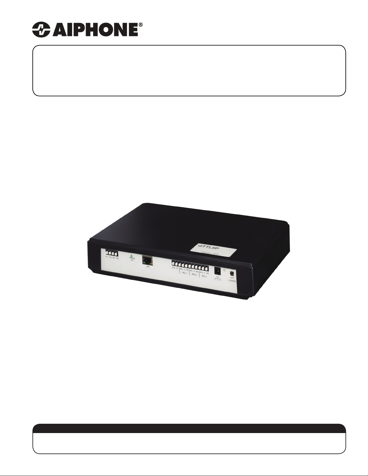
GT-TLI-IP
VoIP Interface for the GT Series
Installation / Operation Instructions
1119
ATTENTION:
This is the installation and operation manual for the GT-TLI-IP only. Refer to the GT Series
Installation and Operation Manual for complete information on all other GT components.
Page 2

Precautions
! WARNING
(Negligence could result in death or serious injury to people.)
• High voltage is present internally. Do not open the case. Electric shock may occur.
• Do not dismantle or alter the unit. Fire or electric shock may occur.
• Do not connect any non-specied power source to the +, - terminals and do not install two power supplies in
parallel to a single input. Fire, damage to the unit, or system malfunction may occur.
• Keep the unit away from water or any other liquid. Fire or electric shock may occur.
• Do not put any metal or paper into the unit through the openings. Fire of electric shock may occur.
• Do not plug or unplug with wet hands. Electric shock may occur.
• Keep AC plug away from moisture or dust as re may occur.
• Keep AC cord from being marred or crushed. If the AC cord is damaged, re or electric shock could occur.
• Do not use a power supply with a voltage other than specied. Fire or electric shock may occur.
• Insert AC plug completely and securely into AC outlet. Otherwise, re or electric shock may occur.
• Do not install or use near gases or ammable materials. Fire or explosion may occur.
! CAUTION
(Negligence could result in injury to people or damage to property.)
• Before turning on power, make sure wires are not crossed or shorted. Fire or electric shock may occur.
• When mounting the unit on wall, install the unit in a convenient location, but not where it could be jarred
or bumped. Injury may occur.
• Do not install or make any wire terminations while power supply is plugged in. It could result in electric shock
or damage to the unit.
• Do not install the unit in any of the following locations. Fire, electric shock, or unit trouble may occur.
- Places under direct sunlight, or near heating equipment that varies in temperature.
- Places subject to dust, oil, chemicals, hydrogen sulde (hot spring).
- Places subject to moisture and humidity extremes, such as bathrooms, cellars, greenhouses, etc.
- Places where temperature is quite low, such as inside a refrigerated area or in front of an air conditioner.
- Places subject to steam or smoke (near heating or cooking surfaces).
- Places where noise generating devices such as dimmer switches or invertor electrical appliances, are close.
• On products with ground terminals, connect to an earth ground. Fire or malfunction may occur if unit is not
properly grounded.
• For DC power systems, use Aiphone power supply model specied with the system. If non-specied product is
used, re or malfunction may occur.
• Do not place anything on top of unit. Fire or unit malfunction may occur.
• Do not mount the unit in a place subjected to constant vibration or impact. If jarred or knocked o the wall,
injury may occur.
GENERAL PRECAUTIONS
• All units, except for the door station, are designed for indoor use only. Do not use outdoors.
• In areas where broadcasting station antennas are close by, the intercom system may be aected
by radio frequency interference.
• If a cellular phone is used close by, the unit may malfunction.
• This product, being a control unit for door release, should not be used as a crime prevention device.
• Keep the unit more than 3 feet away from radio or TV set.
• Due to the environmental sound around the unit, it may hinder smooth communication. This is not a malfunction.
2 | GT-TLI-IP Installation / Operation Instructions
Page 3
Package Contents
• Installation / Operation Instructions
• GT-TLI-IP
• 12V DC power supply
• 1 x Ferrite Core (for Cat-5e/6)
• Quick Installation Sheet
Overview
The GT-TLI-IP is an IP adaptor for the GT Series that will allow mobile devices running the AiphoneGT app to be
connected to answer the call from a visitor and open the door. The GT-TLI-IP adaptor will come with the instructions to
connect up to 3 instances of the mobile app. The GT-TLI-IP can be included in a tenant space with another GT Series
tenant station or it can be used stand-alone so the apps are the only option to answer/release the entrance door.
Installation
A working GT system with at least one entry panel is required when using the GT-TLI-IP VoIP interface adaptor.
The GT-TLI-IP can be desk mounted or wall mounted using the mounting slots on the back of the unit. Ensure that the
mounting location is accessible.
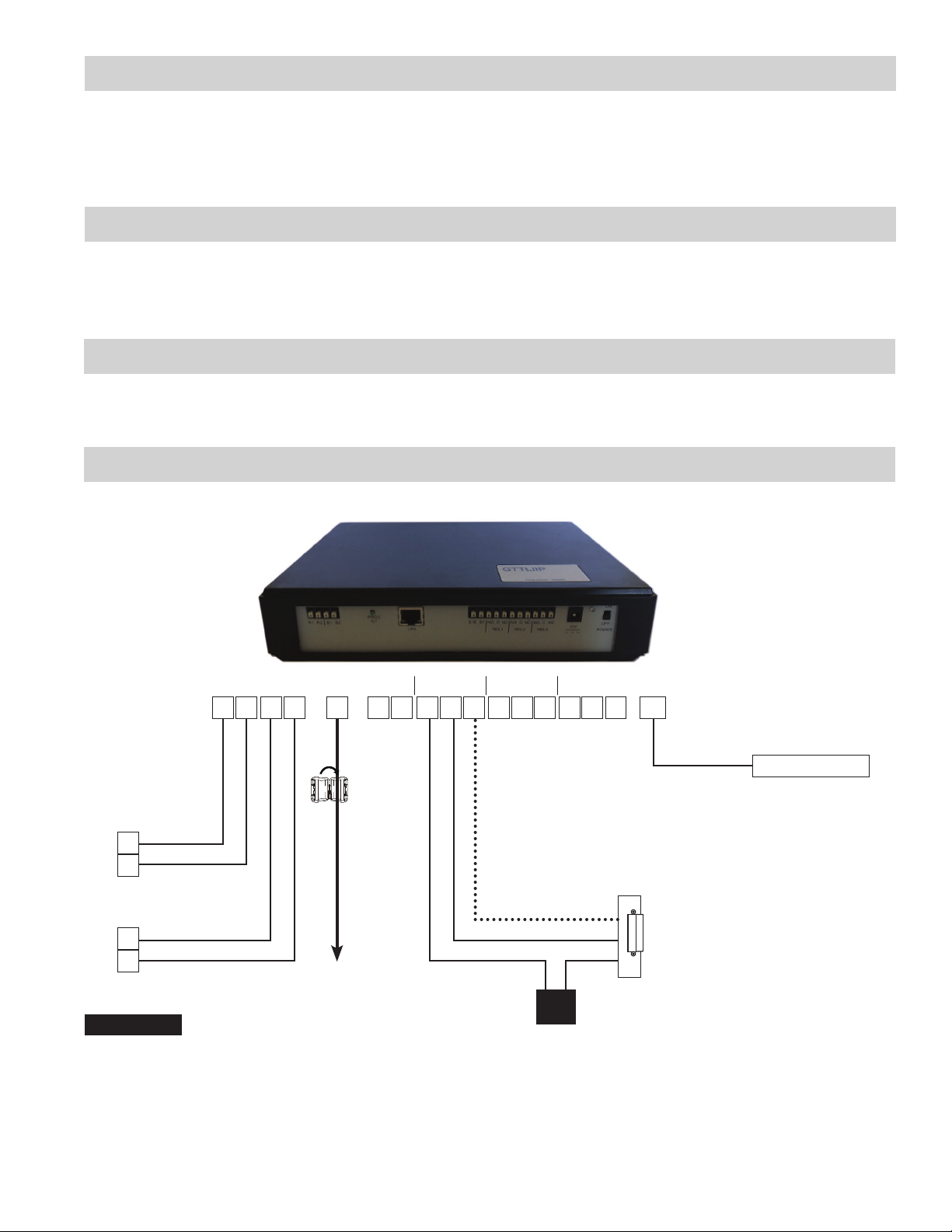
Wiring
GT-TLI-IP
REL 1 REL 2 REL 3
S1E
B1 B2 NO C NC NO C NC
LAN
S1 NO C NCR1 R2 12V
Ferrite
Core
GT-BC
R1
R2
GT-VBC
B1
B2
Cat-5e/6
Network
Connections
R1/R2: Audio cable to GT-BC
B1/B2: Video cable to GT-VBC
LAN: Ethernet Port (RJ45)
S1/S1E: Contact Input
NO/C/NC x 3: 12V DC, 2A; 24V DC, 1A
12V: To power supply 12V DC, 500mA
12V DC Power
Supplied Power
Secondary Dry Contact
PT
3
Page 4
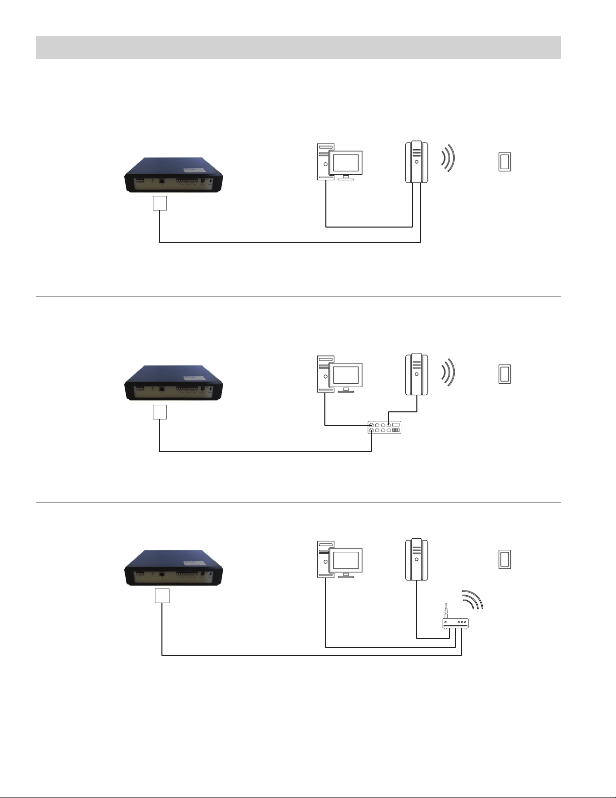
Below are a few examples of connecting the GT-TLI-IP to the network.
Wiring (continued)
Modem with Router
Standard Switch
LAN
LAN
Desktop or
Laptop
Desktop or
Laptop
Modem with
WiFi Router
Modem with
WiFi Router
Smartphone
Smartphone
Modem without Router
LAN
Desktop or
Laptop
Switch
Modem
Smartphone
WiFi Router
4 | GT-TLI-IP Installation / Operation Instructions
Page 5

Direct Select / Push Button Entrance Station Addressing
Step 1:
Step 2:
Step 3:
button and the Power LED will begin ashing. The GT-TLI-IP is now connected to
Step 4:
Step 5:
Step 6:
GT Digital Display Entrance Station Addressing
Step 1:
Step 2:
Step 3:
button and the Power LED will begin ashing. The GT-TLI-IP is now connected to
Step 4:
Step 5:
Step 6:
NAMES
Power LED Indicator
Unit is on when lit.
R1/R2 (GT-BC)
B1/B2 (GT-VBC)
PROG GT: Link
GT-TLI-IP to
system
(program mode)
LAN Port
Linking GT-TLI-IP to GT system
Remove front cover from entrance station.
To enter programming mode, use a small screwdriver to push and release button under the rubber cap on front
of speaker module (GT-DB). The amber LED will begin ashing, then remain lit. Once lit, the entry panel is in
programming mode.
At GT-TLI-IP, press the PROG GT
the entrance panel.
Push and release the desired Call Button on the entrance station to assign the button to the GT-TLI-IP station that is
active. A blip tone will be played.
DO NOT press and hold the Call Button as doing so will clear the memory for this button.
At GT-TLI-IP, press the PROG GT button to complete programming.
To exit programming, push the button under the rubber cap on the GT-DB module again and the amber LED will
turn o. The system is now ready for use.
POWER: Master power switch
(ON/OFF)
12V:
Power input from power supply
Relay 3 (Form C)
Relay 2 (Form C)
Relay 1 (Form C)
Contact Input
Remove front cover from entrance station.
To enter programming mode, use a small screwdriver to push and release button under the rubber cap on front of
speaker module (GT-DB). The amber LED will begin ashing, then remain lit. Once lit, the entrance station is in
programming mode. The LCD will show “CONNECTING” while in programming mode.
At GT-TLI-IP, press the PROG GT
the entrance panel.
Scroll to the station number to be programmed or manually dial the number. When the tenant station number is
displayed, push and release the Bell button to assign the address to the GT-TLI-IP station that is active. A blip
tone will be played.
DO NOT press and hold the Bell Button as doing so will clear the memory for this address.
At GT-TLI-IP, press the PROG GT button to complete programming.
To exit programming, push the button under the rubber cap on the GT-DB module again and the amber LED will
turn o. The system is now ready for use.
5
Page 6

Linking GT-TLI-IP to GT system (continued)
GT-DMB-N Entrance Station Addressing
Step 1: While in standby mode, enter # plus ID code (default is
Step 2: Scroll down to
mode. The amber LED will begin ashing, then remain lit. Once lit, the entry panel is in programming mode. The
LCD will show “CONNECTING” while in programming mode.
Step 3: At GT-TLI-IP, press the PROG GT button and the Power LED will begin ashing. The GT-TLI-IP is now connected to
the entrance panel.
Step 4: Scroll to the station number to be programmed or manually dial the number. When the tenant station number is
displayed, push and release the Bell button to assign the address to the GT-TLI-IP station that is active. A blip
tone will be played and the LCD screen will display “Registered”.
DO NOT press and hold the Bell Button as doing so will clear the memory for this address.
Step 5: At GT-TLI-IP, press the PROG GT button to complete programming.
Step 6: To exit programming, press the “X” button on the panel to return to the programming menu (the amber LED will turn
o). Press the “X” button again to return to the main menu. Scroll to
now ready for use.
PROGRAMMING
. Push the Bell button . Push the bell button again to enter programming
1111). Re-enter ID code.
QUIT
and press the button. The system is
App Set up
The AiphoneGT app can easily be set up and registered using QR codes supplied with the GT-TLI-IP adaptor. A barcode
reader is required on the phone in order to use the QR codes.
1. Install the “AiphoneGT” application on the mobile device.
a. Read the QR code on the back of the GT-TLI-IP or the one below. The mobile device will connect directly to the
corresponding store (Google PlayTM or App Store®).
b. If the QR code does not work, go the store on the mobile device and search for the AiphoneGT application.
6 | GT-TLI-IP Installation / Operation Instructions
Page 7

App Set Up (continued)
2. Launch the “AiphoneGT” application on the mobile device.
The Welcome screen will open.
Auto Entry: Scan one of the
three available QR codes on
the back of the GT-TLI-IP.
Manual Entry: Enter the User
name, Password and Domain
found near the QR code on
the back of the
GT-TLI-IP
sipus.tliip.com
If QR scan does not
work or manual entry
is preferred, click the
edit button.
When the icon is green,
the mobile app is ready to
use. Place a call from the
entrance panel to test station.
7
Page 8

GT-TLI-IP Advanced Settings
The GT-TLI-IP can be congured to send emails with a snapshot of the visitor when a call is placed. The operating
parameters of the GT-TLI-IP can also be adjusted.
Open a web browser and enter http://us.tliip.com in the address bar. The PC will connect to the GT-TLI-IP and the
Welcome to Proxy screen will appear. Select the desired language and enter the Serial Number found on the back of the
GT-TLI-IP into the User eld. Click Connect.
The Welcome to “GT-TLI-IP” adaptor screen will display next. Select the desired language and enter the password found
on the back of the GT-TLI-IP or on the quick installation sheet supplied with the adaptor. Click Log in.
8 | GT-TLI-IP Installation / Operation Instructions
Page 9

GT-TLI-IP Advanced Settings (continued)
The Welcome Screen for the GT-TLI-IP adaptor will be displayed. Click Resident to add an email address to send a
snapshot of the visitor when a call is placed for each instance of the AiphoneGT app.
All 3 available instances of the app for the adaptor will be displayed. Enter an email address for each instance of the app
if that user would like an email sent with a snapshot of the visitor when a call is placed. If the Always box is checked, the
email will be sent to the entered address when any call is placed to the GT-TLI-IP. If the Always box is not checked, the
email will only be sent when that app does not receive the call (i.e. no cell phone coverage).
Click Submit to save and validate any changes made on this page.
9
Page 10

GT-TLI-IP Advanced Settings (continued)
The Welcome Screen for the GT-TLI-IP adaptor will be displayed again. Click on Timing to adjust when the call will end if
answered from the AiphoneGT app.
The Installation Conguration screen will open. From this screen you can select to terminate the call after the door
has been released (Access #1), or to terminate 5 seconds after the door has been released. If these are not set, the
communication will be terminated by the user tapping the end call button on the app or when the communication time-out
is reached.
The adaptor can be set to terminate the call after one of the optional relay outputs is triggered as well. Set the option
outputs accordingly.
Finally, you can set a delay on the GT-TLI-IP adaptor before a call is placed to the mobile app. This would be used if you
wanted to have the call be placed to the tenant station (i.e. GT-1C7, GT-1M3, etc.) before calling to the mobile app. Set the
delay under Outgoing Calls.
Click Submit to save any changes that were made on this screen.
10 | GT-TLI-IP Installation / Operation Instructions
Page 11

AiphoneGT App Operation
Incoming Call Active/Answered Call
Tap to end call
Tap to
reject call
Slide to trigger relay on entrance station
Slide to trigger Relay 1 on GT-TLI-IP
Slide to trigger Relay 2 on GT-TLI-IP
Slide to trigger Relay 3 on GT-TLI-IP
Tap to
answer call
Tap to silence speaker
Tap to mute microphone
Tap to turn o video
Tap for door release options
Door Release Screen
11
Page 12

SPECIFICATIONS
A
iphone Corporation
(800) 692-0200
Dimensions 10-¼" x 7-1⁄16" x 2-1⁄16" (260mm x 180mm x 53mm)
Weight 1.35 lbs (0.6 kg)
Temperature 32°F - 140°F (0°C - 40°C)
Connections 1 Cat-5e/6 Ethernet for network
2 two conductor cables for GT bus (audio-872002, video-871802)
Power required 12V DC, 500mA
Consumption Standby: 350mA
Active relay: 430mA
Standards EN60950
EN55032 Edition 2015 Class B
EN55024 Edition 2015 Class B
FCC part 15 Subpart B
Programming Via web browser
Capacity 3 mobile apps
Memory Non-volatile memory
Chassis ABS plastic
WARRANTY
Aiphone warrants its products to be free from defects of material and workmanship under normal use
and service for a period of two years after delivery to the ultimate user. Aiphone will repair free of charge
or replace at no charge should the product become defective upon which examination shall disclose to
be defective and under warranty. Aiphone reserves unto itself the sole right to make the nal decision
whether there is a defect in materials and/or workmanship; and whether or not the product is within the
warranty. This warranty shall not apply to any Aiphone product which has been subject to misuse, neglect,
accident, or to use in violation of instructions furnished, nor extended to units which have been repaired or
altered outside of the factory. This warranty does not cover batteries or damage caused by batteries used
in connection with the unit. This warranty covers bench repairs only and any repairs must be made at the
shop or place designated in writing by Aiphone. Aiphone will not be responsible for any costs incurred
involving on-site service calls.
This equipment has been tested and found to comply with the limits for a Class B digital device, pursuant
to Part 15 of the FCC Rules. These limits are designed to provide reasonable protection against harmful
interference in a residential installation. This equipment generates, uses, and can radiate radio frequency
energy, and if not installed and used in accordance with the instructions, may cause harmful interference
to radio communications. However, there is no guarantee that interference will not occur in a particular
installation. If this equipment does cause harmful interference to radio or television reception, which can be
determined by turning the equipment o and on, the user is encouraged to try to correct the interference by
one of more of the following measures:
• Reorient or relocate the receiving antenna
• Connect the equipment into an outlet on a circuit dierent from that to which the receiver is connected.
• Increase the separation between the equipment and receiver.
• Consult the dealer or an experienced radio/TV technician for help.
12 | GT-TLI-IP Installation / Operation Instructions
FCC REQUIREMENTS
www.aiphone.com
tech@aiphone.com
 Loading...