

Page 1
IS SERIES
Commercial & Security IP Video Intercom system
Network Direct System
SETTING MANUAL
FK1629 B 0811YZ
Thank you for selecting Aiphone for your communication and security needs. Please read this manual and the separate
“OPERATION MANUAL” carefully before setting and using this system.
*
Refer to the provided “INSTALLATION MANUAL” for complete information regarding this system.
IMPORTANT
Please read and understand the system setting procedures before beginning the setup process.
Please note that images and illustrations depicted in this manual may differ from the actual ones.
Page 2

CONTENTS
ABOUT THIS MANUAL ............... 3
PURPOSE OF THE SYSTEM
SETTINGS ................................... 3
SETTING LIST ............................. 4
SYSTEM SETTING FLOW .......... 8
Flow 1 ............................................. 9
Flow 2 ........................................... 10
Flow 3 ............................................11
Remote site connection
settings ........................................ 12
STARTING UP THE SYSTEM
AND PREPARING FOR THE
SETTINGS ................................. 13
System requirements for PC ..... 13
Starting up the system ............... 13
THE SYSTEM SETTING
DETAILS .................................... 15
The basic setting procedure ...... 15
Making network settings to
each IP unit [Network setting:
Individual] .................................... 16
Making network settings for
the whole system [Network
setting: Common] ....................... 16
Setting the administrator ID
and password [Administrator
setting] ......................................... 17
Confi rming the IP units
connected to the system
[IP unit search] ............................ 17
Registering areas and remote
sites [System setting – Area/Site
registration] (Required) .............. 18
Registering zones [System
setting – Zone registration] ....... 18
Registering IP units [System
setting – IP unit registration] ..... 19
Registering stations [System
setting – Registering stations] .. 20
Making detailed settings to
stations [System setting –
Advanced station settings] ........ 21
Basic setting procedure ..........................21
Making detailed settings to door
stations ..................................................21
Making detailed settings to master
stations ..................................................22
Registering stations to zones
[System setting – Zone
setting] ......................................... 23
Registering daily transfer
schedule [Transfer setting –
Registering daily transfer
schedule] ..................................... 23
Setting transfer schedule
[Transfer setting – Transfer
schedule setting] ........................ 24
Setting the timer
[Timer setting]
Setting stations to receive
calls and zones to receive
paging from remote sites
[Remote site pilot call setting] ... 26
Video setting ............................... 27
Setting time and date
[Time and date setting] .............. 27
E-mail setting .............................. 28
Downloading/uploading setting
data [Setting fi le] ......................... 28
When downloading setting data
■
onto the PC ........................................28
When uploading setting data ..............28
■
Updating the system
[Updating the system] ................ 28
............................. 25
MAINTENANCE ......................... 29
Initializing the system
[Initialization] ............................... 29
Downloading system log
[System log] ................................ 29
Updating the fi rmware
[Firmware update] ....................... 29
Downloading updated fi rmware
■
data ....................................................29
Referring to the troubleshooting
guide [Troubleshooting] ............. 29
Registering your system
[Registration] ............................. 29
Setting Information Memo ...... 30
2
Page 3

ABOUT THIS MANUAL
The IS system provides various manuals to meet various system planning and work processes. Use the manuals necessary for your
system.
Manual confi gurations
The following manuals are provided for a network direct system. Read all the manuals for installing, setting up, and using a network
direct system, or provide the manuals to the persons working with the system.
INSTALLATION MANUAL (A booklet included with the IP master station (IS-IPMV))
Used for installing and connecting IP master stations and IP video door stations. (For an installer or serviceman)
SETTING MANUAL (This manual on the CD-ROM included with the IP master station (IS-IPMV))
This manual describes how to make the system settings and system maintenance. (For an installer or serviceman)
OPERATION MANUAL (An electronic manual on the CD-ROM included with the IP master station (IS-IPMV))
Information for using the system for calling, communicating, paging, monitoring, etc. (For users of the system)
Note the following:
•
This manual describes how to make the system settings for a network direct system (without an IP control unit) only. For a standard
(IP) system (including one or more IP control units), refer to the “SETTING MANUAL” for the standard (IP) system.
•
Master stations and door stations that can be used in a network direct system are IP units (IS-IPMV, IS-IPDV, IS-IPDVF and ISSOFT) only.
•
PC master stations (IS-SOFT) can also be used in a network direct system. For setting a PC master stations (IS-SOFT), refer to
the “SETTING MANUAL” for the PC master station (IS-SOFT).
GETTING STARTED USING THE SYSTEM APPENDIX
SETTING THE SYSTEM
PURPOSE OF THE SYSTEM SETTINGS
Confi gure the system settings based on how your system is planned to be used. System settings must be completed before the
system will operate.
CAUTION:
Make the settings correctly. If the settings are not made correctly, the system will not function as planned.
3
Page 4
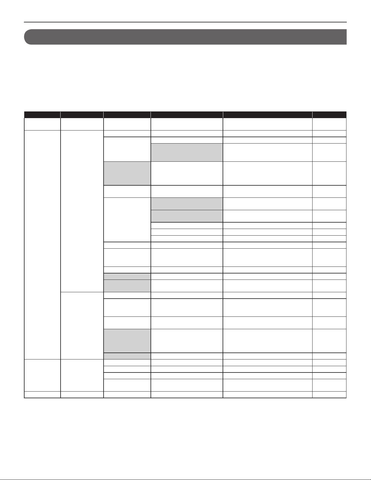
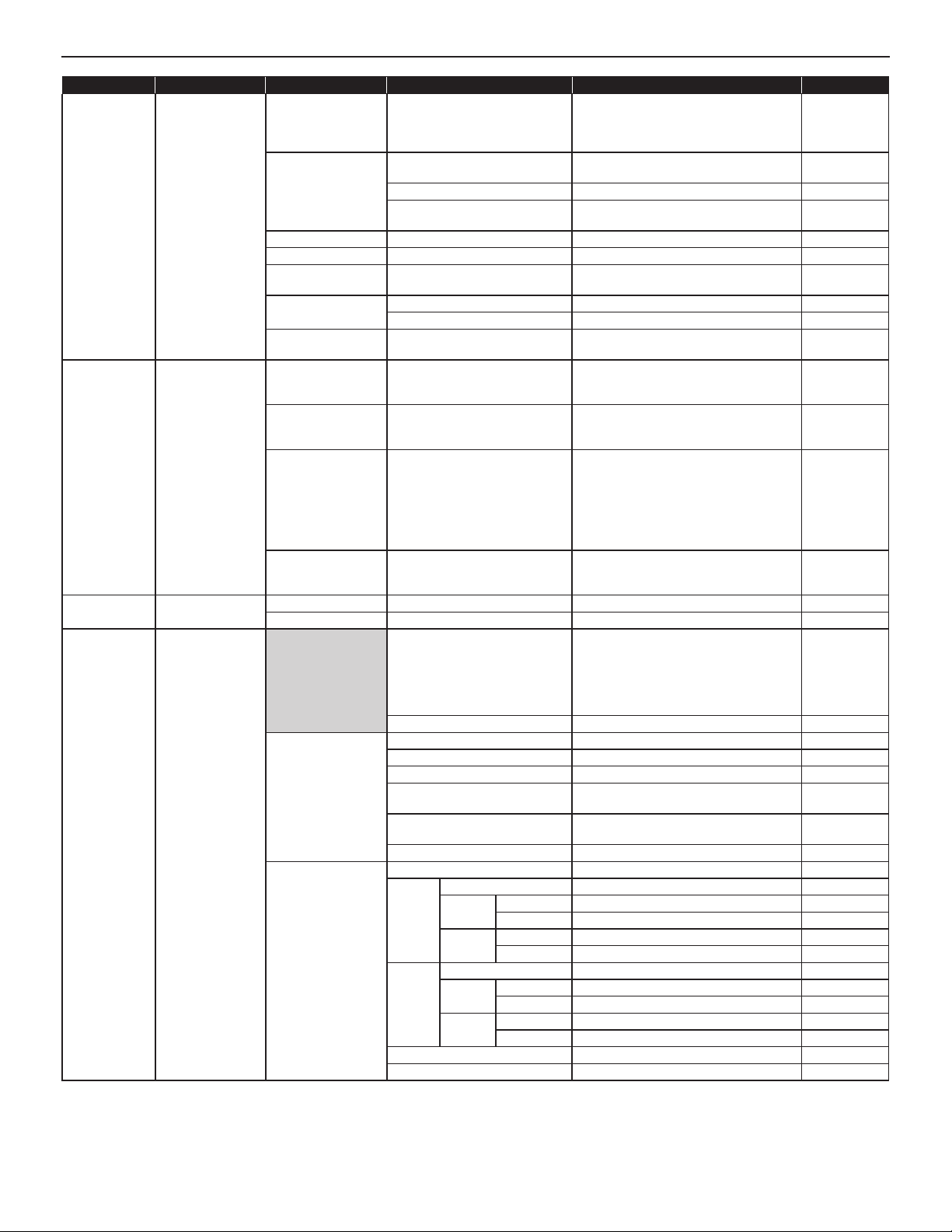
SETTING LIST
The following is the list of system settings you can make via the web browser. The titles or items in shaded cells are required.
NOTES:
•
The following list is a brief overview of the setting items available in the system settings on a PC. The descriptions, and the style and order of
descriptions do not necessarily equate with the actual displays.
•
The following list describes the setting contents required only for a network direct system. The actual setting windows of the web browser also
includes contents not described in the list.
•
Make a note of the setting results you have made by using the “Setting Information Memo” (
keep it in a safe place not to lose it.
Title Sub title Item Sub item Setting range Default
- - (Language) - English/French/German/Spanish/Dutch/
Network setting Network setting:
Administrator
setting
IP unit search - - - - -
Individual
Network setting:
Common
- New administrator ID - Up to 16 alphanumeric characters -
IP version - IPv4 IPv4
Host unit setting - Host unit/Client unit Client unit
Host unit IP address (available
when [Host unit setting] is set to
“Client unit”)
System name
(available when [Host
unit setting] is set to
“Host unit”)
(Select the network
setting method.)
Static IP Address Static IP Address (required when
MAC address - (Unmodifi able) (Unmodifi able)
Unit name - Up to 24 alphanumeric characters
Web port - (Unmodifi able) (Unmodifi able)
Connection port - 1024 - 65535 5060
Connection
Password
UPnP - ON/OFF ON
Global IP address
(available when
[UPnP] is set OFF)
Connection port:
global
Multicast address
1 - 5 (“Multicast
address 3” is not
available.)
Audio/video port - 1024 - 65535 50800 - 50813
Current Password - Up to 16 alphanumeric characters - (aiphone)
New Password - Up to 16 alphanumeric characters New Password
(Re-type)
- Up to 24 alphanumeric characters -
- DHCP/Static IP Address DHCP
[Static IP Address] is selected)
Subnet Mask (required when
[Static IP Address] is selected)
Default Gateway 0 – 255 (for each fi eld) -
Primary DNS Server 0 – 255 (for each fi eld) -
Secondary DNS Server 0 – 255 (for each fi eld) -
- Up to 16 alphanumeric characters aiphone
- 0 - 255 (for each fi eld) -
- (Unmodifi able) (Unmodifi able)
- 239.0.0.0 - 239.255.255.255 1: 239.0.1.1
- Up to 16 alphanumeric characters -
P. 30) etc. in case of unexpected data erasure, and
→
Italian/Japanese
(Enter the Host unit IP address.) -
0 – 255 (for each fi eld) 192.168.0.40
0 – 255 (for each fi eld) 255.255.255.0
(except accent marks, umlaut marks,
etc.)
English
-
2: 239.0.1.2
4: 239.0.1.4
5: 239.0.1.5
4
Page 5
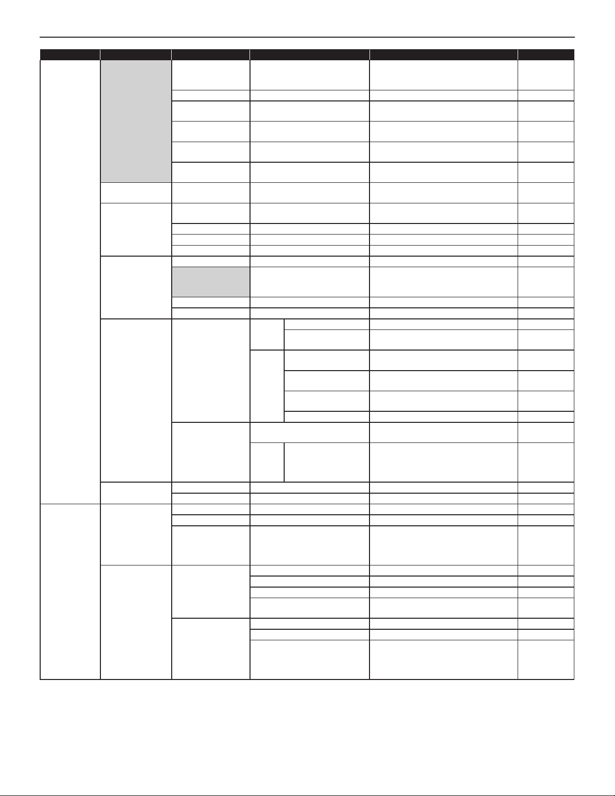
Title Sub title Item Sub item Setting range Default
System setting Area/Site
registration
Zone registration Zone name - Up to 24 alphanumeric characters (for
IP unit registration Station type - IP video door station, IP master station,
Registering
stations
Advanced station
settings
Zone setting Zone number - (Select from the registered ones.) -
Transfer setting Registering daily
transfer schedule
Transfer schedule
setting
Area/Site Name - Up to 24 alphanumeric characters (for
Area/Site - Area/Site Area
IP Address (sites
only)
Port number (sites
only)
Connection
Password (sites only)
Door release (sites
only)
MAC address - - Unit name - Up to 24 alphanumeric characters Port number - 1024 - 65535 50900 - 50902
Area - (Area) 01 to 99 (Area) 01
Station number - 001 to 999
Station name - Up to 24 alphanumeric characters Station type - (Unmodifi able) (Unmodifi able)
Video door station
Master station Stations to be scan monitored (Select up to 20 sub stations from the
Stations - (Select from the list.) Schedule number - DT1/DT2 DT1
Schedule name - Up to 24 alphanumeric characters Call transfer time - Hour: 0 to 23
Weekly schedule (Repeat setting) Every week/Every other week Every week
Individual schedule (Date) From the current day to 1 year ahead -
- 0 - 255 (for each fi eld) -
- 1024 - 65535 -
- Up to 16 alphanumeric characters -
- ON/OFF ON
Call priority Normal/Priority/Urgent Normal
Called stations (Set up to 20 targets from the registered
Called
stations
Transmit volume boost
at PTT
Camera zoom image
preset
Other
Call acknowledge tone
on/off
Backlight adjustmentExposure +/Exposure - Exposure +
Master station function:
paging, chime, monitor,
door release, and
Other
remote site call
Schedule start date From the current day to 1 year ahead Schedule end date From the start day to 1 year ahead (Transfer schedule) None/DT1/DT2 (for each day of the
Daily transfer schedule (Select from the registered ones.) None
Call transfer time Hour: 0 to 23
up to 99 areas including sites)
* Up to 31 for sites
up to 99 zones)
PC master station
0001 to 9999
00001 to 99999
ones.)
ON/OFF
(ON: approx. +6dB up)
0 (wide)/1/2/3/4/5/6/7/8/9 (zoom) 5 (Center)
ON/OFF ON
registered ones.)
ON/OFF ON
Minute: 0 to 59
(Set to the Start time and End time
individually.)
week)
Minute: 0 to 59
(Set to the Start time and End time
individually.)
1 (for Area
number 01)
-
-
-
-
OFF
-
-
None
-
GETTING STARTED USING THE SYSTEM APPENDIX
SETTING THE SYSTEM
5
Page 6
Title Sub title Item Sub item Setting range Default
Timer setting - Call Normal/Priority/Urgent 10 to 600 (sec.), 0 (Unlimited)
Normal: 30 (sec.)
Priority: 90 (sec.)
Urgent: 0
(Unlimited)
Communication In Local (Not available) 30 to 600 (sec.) (Not used for network
60 (sec.)
direct system)
Via IP 30 to 600 (sec.) 60 (sec.)
Telephone (Not available) 30 to 600 (sec.) (Not used for network
120 (sec.)
direct system)
Paging - 30 to 600 (sec.) 60 (sec.)
Monitor - 10 to 600 (sec.) 60 (sec.)
Scan monitor:
- 5 to 60 (sec.) 7 (sec.)
Switching
Contact output
(Not available)
Door release -
External sound source 1 10 to 300 (sec.) 30 (sec.)
External sound source 2 10 to 300 (sec.) 30 (sec.)
0 to 300 (sec.), (0: Released while
10 (sec.)
holding the Door release button pressed.)
Remote site
pilot call setting
- Remote site master
call
Normal/Priority/Urgent (Select one from the registered stations
in your site for each of “Normal”, “Priority”
-
and “Urgent”.)
Remote site door call Normal/Priority/Urgent (Select up to 20 stations from the
registered master stations in your site for
each of “Normal”, “Priority” and “Urgent”.)
Remote site room
sub call (available
when the remote site
Normal/Priority/Urgent (Select up to 20 stations from the
registered master stations in your site for
each of “Normal”, “Priority” and “Urgent”.)
-
is a standard (IP)
system that includes
room sub stations
(IS-RS).)
Remote site paging Normal/Priority/Urgent/
Broadcast
(Select one from the registered zones in
your site for each of “Normal”, “Priority”,
-
“Urgent” and “Broadcast”.)
Video setting - Frame Rate - 1/2/5/7.5/10/15 (fps) 15 (fps)
Quality - Low, Middle, High, Excellent Excellent
Time and date
setting
- Set current time Manual setting Year: 2009 to 2099
Month: 1 to 12
Day: 1 to 31
(Internal time
of the IP Host
unit)
Hour: 0 to 23
Minute: 0 to 59
Second: 0 to 59
Synchronized with PC - -
NTP Synchronized with NTP server ON/OFF OFF
NTP server*
NTP port number*
(UTC time zone*
Hour difference*
(UTC time zone*
Minute difference*
1
1
1
)
1
1
)
1
IP address or domain name 1 to 65535 123
-12 to +13 (h) 0
-45/-30/0/+30/+45 (m) 0
Synchronize interval 1 to 240 (h) 24 (h)
Daylight savings time - ON/OFF OFF
Starts*
2
Month JAN to DEC (M) JAN
Day (Week) 1st to 4th (W)/The last 1st
(Day) Sunday to Saturday Sunday
Hour (Hour) 0 to 23 (h) -
(Minute) 0 to 59 (m) -
Ends*
2
Month JAN to DEC (M) JAN
Day (Week) 1st to 4th (W)/The last 1st
(Day) Sunday to Saturday Sunday
Hour (Hour) 0 to 23 (h) -
(Minute) 0 to 59 (m) Hour difference*
Minute difference*
*1: Available only when [Synchronized with NTP server] is set to ON.
2
*
: Available only when [Daylight savings time] is set to ON.
2
2
0 to 12 (h) 1
0/30/45 (m) 0
6
Page 7

Title Sub title Item Sub item Setting range Default
E-mail setting
Setting fi le
- Email destination
Downloading
setting data
Uploading setting
data
address
Email source
address
SMTP authentication SMTP server Up to 256 alphanumeric characters -
Language selection
Mailing event Call: Normal ON/OFF OFF
-- - -
-- - -
1/2/3 Up to 256 alphanumeric characters -
- Up to 256 alphanumeric characters -
SMTP server port 1 to 65535 465
(Email) login ID Up to 256 alphanumeric characters Password Up to 64 alphanumeric characters -
-
Call: Priority ON/OFF OFF
Call: Urgent ON/OFF OFF
System start ON/OFF OFF
Data communication error in the
system
English/French/German/Spanish/Dutch/
Italian/Japanese
ON/OFF OFF
GETTING STARTED USING THE SYSTEM APPENDIX
English
SETTING THE SYSTEM
7
Page 8
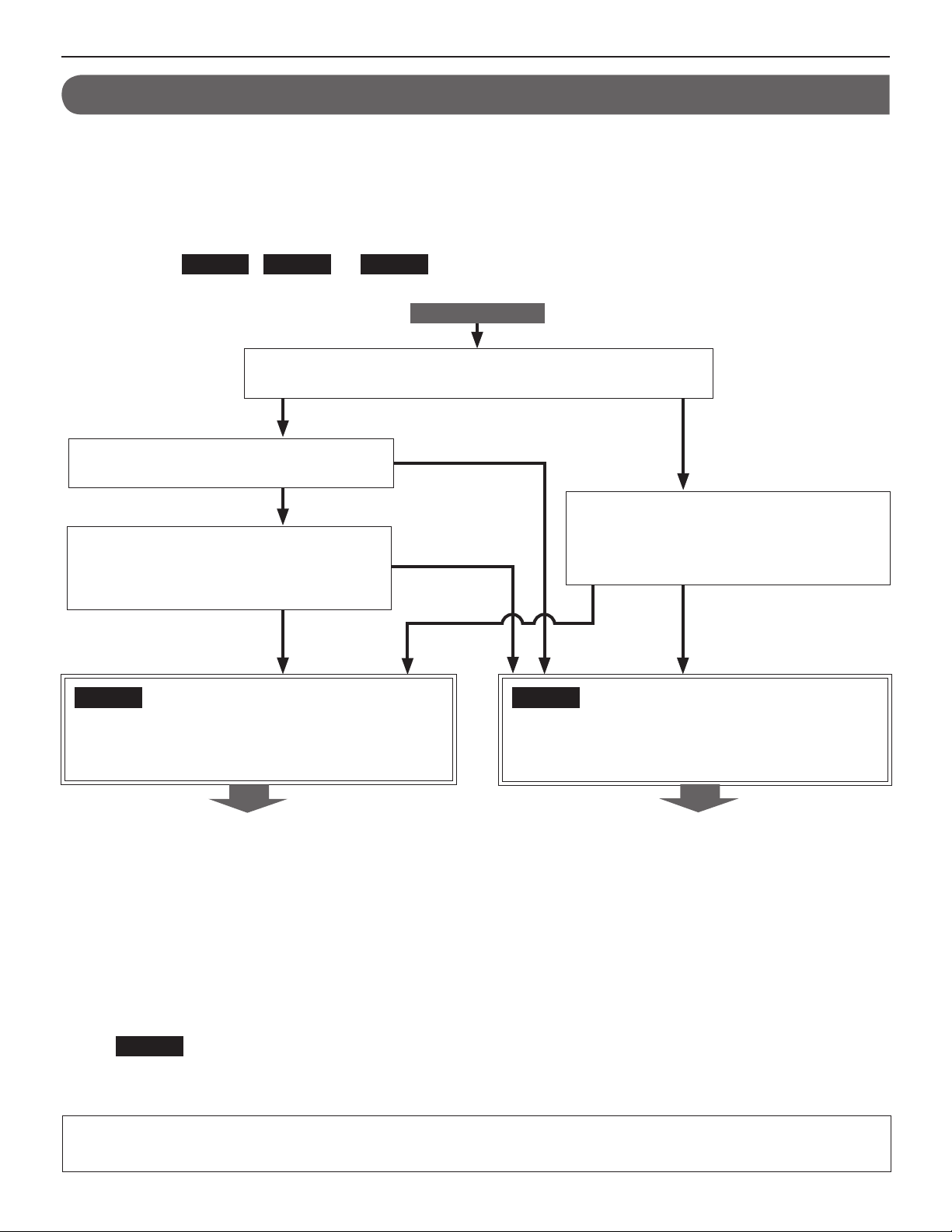
SYSTEM SETTING FLOW
First of all, make the network settings. The network setting method differs according to the network environment. Select the fl ow
suitable for your network environment from the chart below, and start the network settings after you fully understand it. After the
network settings are fi nished, make the other individual system settings. See P. 15-28 for the system setting details.
NOTE:
The system settings should be made mainly on the IP host unit in the system (in a site). You select one as the IP host unit among the IP units
connected to the system and others as the IP client units. (A PC master station (IS-SOFT) cannot be used as the IP host unit.)
First select the
Flow 1
,
Flow 2
or
following the selected fl ow.
Do you communicate with remote sites (calling, call transferring,
paging, etc.)?
YES
Do you use a router on which UPnP functions,
and does UPnP function normally?
YES
Do you have a DHCP server (or router that
has a DHCP server function) in the network,
and does it have an automatic IP addressassigning function?
(*3)
YES
Flow 1
Flow 3
(*1)
from the chart below, then start the network settings by
START
NO
(*4)
NO
Do you have a DHCP server (or router that
has a DHCP server function) in the network,
NO
(*3)
and does it have an automatic IP addressassigning function?
YES NO
(*2)
Flow 2
(IP host unit: A static IP address is set,
IP client units: IP addresses are assigned by the DHCP
server automatically)
Go to P. 9.
NOTE:
If you connect a PC master station (IS-SOFT) to the network, install the software (IS-SOFT) to a PC before connecting it to the network.
(*1): UPnP may not function normally depending on the router. Refer to [System log]→[UPnP operation check result] (→P. 29) on the
IP host unit. If the [System log] window shows that UPnP is not functioning normally, the UPnP function of the router cannot be
used with this system. In that case, set [UPnP] to OFF at [Network setting: Common] (→P. 16) and then make settings on the
router again by confi rming the settings at [IP unit registration] (→P. 19). See http://www.aiphone.net/ for the router to which the
operartion check has fi nished and setting examples.
(*2): If the DHCP server (or router that has a DHCP server function) has a function to assign a static IP address to a specifi ed MAC
address, you can make the DHCP server assign the IP addresses to all the IP units automatically.
(→
Flow 3
(*3): Set [UPnP] to ON at [Network setting: Common] (→P. 16) (Default: ON).
(*4): Set [UPnP] to OFF at [Network setting: Common] (→P. 16) (Default: ON).
If you communicate with remote sites (calling, call transferring, paging, etc.), make the remote site connection settings (→P. 12)
after the network settings for your site have fi nished.
(All units: IP addresses are assigned by the DHCP server automatically) (P. 11))
(All units: Static IP addresses are set)
Go to P. 10.
8
Page 9
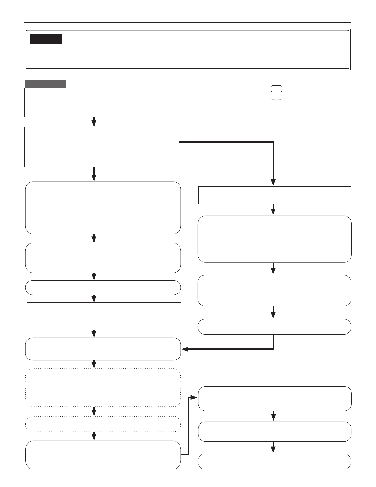
Flow 1
(IP host unit: A static IP address is set,
IP client units: IP addresses are assigned by the DHCP server automatically)
* This is the outline of setting fl ow. Also make the detailed settings on each setting window referring to the corresponding pages.
START
Write down the MAC addresses of all the IP units to be used
in the system in advance by using the “Setting Information
Memo” (→P. 30) etc.
*
The MAC address is labeled on each unit.
Decide the static IP address for the IP unit to be used as the
IP host unit.
*
Use an address out of the range of DHCP assignment for the IP host
unit in order to prevent the address for the IP host unit being assigned
to another IP client unit by an infl uence of the turn-on order between
the IP host unit and the router (that has a DHCP server function) etc.
(When making the IP host unit settings
before connecting the units to the network)
Connect the IP host unit and the PC used for settings
directly, and then turn them on. After a while, access
"https://192.168.0.40/" from the browser on the PC. (→P. 14)
NOTES:
•
When connecting a PC to the IP unit directly, use an Ethernet
crossover cable.
•
If a warning dialog box for security or guarding against virus
programs appears when accessing the web browser, give permission.
(Log in.)
Make the [Network setting: Individual] settings on the IP
host unit. (→ P. 16)
*
Set it as "Host unit".
*
Set the static IP address to the IP host unit.
(When making the IP host unit settings
after connecting the units to the network)
Connect the units and the PC used for settings to the
network, and then turn them on.
Search for the IP address of the IP host unit from the MAC
address of the IP host unit by using IS_IPSEARCH.exe (in the
CD-ROM included with the IP master station (IS-IPMV)). (If
the address does not appear, repeat this step until it appears.)
Then access the address from the browser on the PC. (→P. 14)
*
This address is the temporary one for the initial setting.
: Settings on the IP host unit
: Settings on the IP client units
(Log in.)
GETTING STARTED USING THE SYSTEM APPENDIX
SETTING THE SYSTEM
Make the [Network setting: Individual] settingson the IP
Update the system at [Updating the system]. (→ P. 28)
host unit. (→ P. 16)
*
Set it as "Host unit".
*
Set the static IP address to the IP host unit.
Connect the units and the PC used for settings to the
network, and then turn them on.
(IP addresses are assigned to the IP client units by the
DHCP server automatically.)
Update the system at [Updating the system]. (→ P. 28)
Search for the IP units (other than PC master stations) you
will use in the system at [IP unit search] on the IP host unit,
and open the setting window for each IP unit. (→ P. 17)
Make the [Network setting: Individual] settings on the IP
client units. (→ P. 16)
*
Set them as "Client unit" (if they are not set as "Client unit").
*
Enter the IP address of the IP host unit.
*
Select "DHCP" for acquiring IP addresses (if "DHCP" is not selected).
Update the system at [Updating the system]. (→ P. 28)
Add IP units you will use in the system at [IP unit
registration] on the IP host unit. (→ P. 19)
If you will connect your site with remote sites, make the
remote site connection settings. (→ P. 12)
Confi rm the [Network setting: Common] settings on the IP
host unit. (→ P. 16)
*
Confi rm that the multicast addresses and/or port numbers do not overlap those
of other manufacturer’s network devices connected to the same network.
Make the other system settings. (→ P. 17-28)
9
Page 10
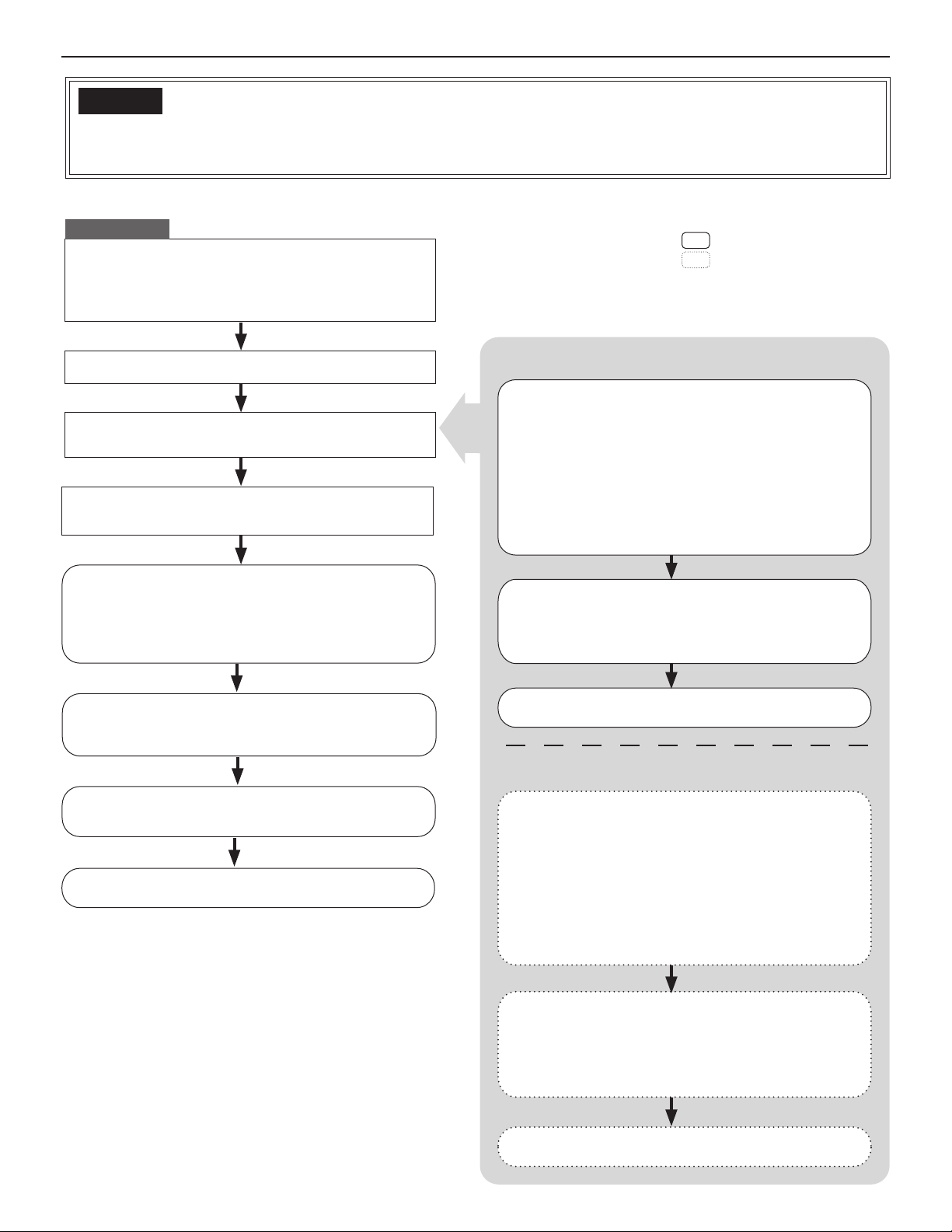
Flow 2
(All units: Static IP addresses are set)
* This is the outline of setting fl ow. Also make the detailed settings on each setting window referring to the corresponding pages.
START
Write down the MAC addresses of all the IP units to be
used in the system in advance by using the “Setting
Information Memo” (→P. 30) etc.
*
The MAC address is labeled on each unit.
Decide the static IP address for each IP unit.
Make the [Network setting: Individual] settings on each
IP unit individually. (→ P. 16)
Connect the units and the PC used for settings to the
network, and then turn them on respectively.
Confi rm the [Network setting: Common] settings on the
IP host unit. (→ P. 16)
*
Confi rm that the multicast addresses and/or port
numbers do not overlap those of other manufacturer’s
network devices connected to the same network.
: Settings on the IP host unit
: Settings on the IP client units
For the IP host unit
Connect the IP host unit and the PC used for settings
directly, and then turn them on. After a while, access
"https://192.168.0.40/" from the browser on the PC.
(→P. 14)
NOTES:
•
When connecting a PC to the IP unit directly, use an
Ethernet crossover cable.
•
If a warning dialog box for security or guarding against virus
programs appears when accessing the web browser, give permission.
(Log in.)
Make the [Network setting: Individual] settings on the
IP host unit. (→ P. 16)
*
Set it as "Host unit".
*
Set the static IP address to the IP host unit.
Add IP units you will use in the system at [IP unit
registration] on the IP host unit. (→ P. 19)
(The selected unit is added in the list whenever selected.)
If you will connect your site with remote sites, make the
remote site connection settings. (→ P. 12)
Make the other system settings. (→ P. 17-28)
Update the system at [Updating the system]. (→ P. 28)
For each IP client unit
Connect an IP client unit and the PC used for settings
directly, and then turn them on. After a while, access
"https://192.168.0.40/" from the browser on the PC.
(→P. 14)
NOTES:
•
When connecting a PC to the IP unit directly, use an
Ethernet crossover cable.
•
If a warning dialog box for security or guarding against virus
programs appears when accessing the web browser, give permission.
(Log in.)
Make the [Network setting: Individual] settings on the
IP client unit. (→ P. 16)
*
Set it as "Client unit".
*
Enter the IP address of the IP host unit.
*
Set the static IP address to the IP client unit.
Update the system at [Updating the system]. (→ P. 28)
10
Page 11

Flow 3
(All units: IP addresses are assigned by the DHCP server automatically)
* This is the outline of setting fl ow. Also make the detailed settings on each setting window referring to the corresponding pages.
START
Write down the MAC addresses of all the IP units to be used
in the system in advance by using the “Setting Information
Memo” (→P. 30) etc.
*
The MAC address is labeled on each unit.
Set the router (or DHCP server) so that it assigns a static IP
address to the IP unit to be used as the IP host unit.
Connect the units and the PC used for settings to the
network, and then turn them on.
Access the IP address assigned to the IP host unit from the
browser on the PC. (→P. 14)
(Log in.)
: Settings on the IP host unit
: Settings on the IP client units
GETTING STARTED USING THE SYSTEM APPENDIX
SETTING THE SYSTEM
Make the [Network setting: Individual] settings on the IP
host unit. (→ P. 16)
*
Set it as "Host unit".
*
Select "DHCP" for acquiring an IP address.
Update the system at [Updating the system]. (→ P. 28)
Search for the IP units (other than PC master stations) you
will use in the system at [IP unit search] on the IP host unit,
and open the setting window for each IP unit. (→ P. 17)
Make the [Network setting: Individual] settings on the IP
client units respectively. (→ P. 16)
*
Set them as "Client unit" (if they are not set as "Client unit").
*
Enter the IP address of the IP host unit.
*
Select "DHCP" for acquiring IP addresses (if "DHCP" is not
selected).
Update the system at [Updating the system]. (→ P. 28)
Confi rm the [Network setting: Common] settings on the IP
host unit. (→ P. 16)
*
Confi rm that the multicast addresses and/or port numbers
do not overlap those of other manufacturer’s network
devices connected to the same network.
Add IP units you will use in the system at [IP unit
registration] on the IP host unit. (→ P. 19)
If you will connect your site with remote sites, make the
remote site connection settings. (→ P. 12)
Make the other system settings. (→ P. 17-28)
11
Page 12

Remote site connection settings
You need to make the remote site connection settings to enable communication between your site and remote sites. Make the settings
by following the procedure below after the network settings for your site have fi nished.
* This is the outline of setting fl ow. Also make the detailed settings on each setting window referring to the corresponding pages.
Procedure
Complete the network settings for your site by following
Flow 1
Get the following information for the remote sites you will
connect with your site.
"Global IP address"
"Connection port: global"
"Connection Password"
Set the following setting items on the IP host unit. (→ P. 16)
[Network setting: Individual] :
"Default Gateway"
[Network setting: Common] :
"UPnP"
"Global IP address"
"Audio/video port"
,
Flow 2
or
Flow 3
. (→P. 9-11)
: Settings on the IP host unit
: Required when [UPnP] is set
to OFF at [Network setting:
Common] (→ P. 16)
Make the [Area/Site registration] on the IP host unit. (→ P. 18)
* Select "Site" with the "Area/Site" pull-down menu and enter
the information of the site you will connect.
Update the system at [Updating the system]. (→ P. 28)
Open the [IP unit registration] window on the IP host unit,
and then click the
*
Another window opens and the port forwarding setting
contents are displayed.
Set the router with the port forwarding setting contents you
confi rmed in the previous step.
Port forwarding setting
button. (→ P. 19)
12
Page 13

STARTING UP THE SYSTEM AND PREPARING FOR THE SETTINGS
The system settings are mainly made on the PC by accessing the web browser for the settings incorporated with the IP unit as the IP
host unit. It is recommended to use only one PC for the settings that is connected to the system.
System requirements for PC
Your PC and operating environment must meet the following system requirements to make the settings.
Network 10BASE-T Ethernet, 100BASE-TX Ethernet
Web browser Internet Explorer 6.0 or later (with Internet Options SSL 3.0 enabled)
Starting up the system
Connect a PC to the IP unit.
1
[When connecting a PC to the IP unit via a hub
(switch)]
IP master station
(IS-IPMV)
IP video door station
(IS-IPDV or IS-IPDVF)
or
[When connecting a PC to the IP unit directly]
IP master station
(IS-IPMV)
IP video door station
(IS-IPDV or IS-IPDVF)
or
GETTING STARTED USING THE SYSTEM APPENDIX
SETTING THE SYSTEM
LAN/PoE
RJ45
100m (330')
10BASE-T/
100BASE-TX
CAT5e/6
(Straight-through cable)
RJ45
Hub
(Switch)
RJ45
100m (330')
10BASE-T/
100BASE-TX
RJ45
PC
CAT5e/6
(Straight-through
cable)
NOTES:
•
Be sure to connect the CAT5e/6 cable to the LAN ports of both
units.
•
The IP address of IP unit is set to (192.168.0.40) and Subnet
Mask is set to (255.255.255.0) as default. Change the IP
address of your PC if needed.
LAN/PoE
RJ45
CAT5e/6 (Crossover cable)
100m (330')
10BASE-T/100BASE-TX
RJ45
NOTES:
•
When connecting a PC to the IP unit directly, use an Ethernet
crossover cable.
•
The IP address of IP unit is set to (192.168.0.40) and Subnet
Mask is set to (255.255.255.0) as default. Change the IP
address of your PC if needed.
(Continued on next page)
PC
13
Page 14
Turn on the power to the IP unit.
2
*
If the unit is connected to a switch or injector that has
a PoE function, the power is being supplied. If a power
supply unit is connected to the unit, turn on the power of
the power supply unit.
*
Turn on all the units constituting the system depending
on the network setting method.
*
The status LED of an IP video door station changes from
red lighting to orange blinking.
(When the settings have correctly made, it changes to
orange lighting.)
The status LED of an IP master station changes from red
lighting to red blinking.
(When the settings have correctly made, it turns off.)
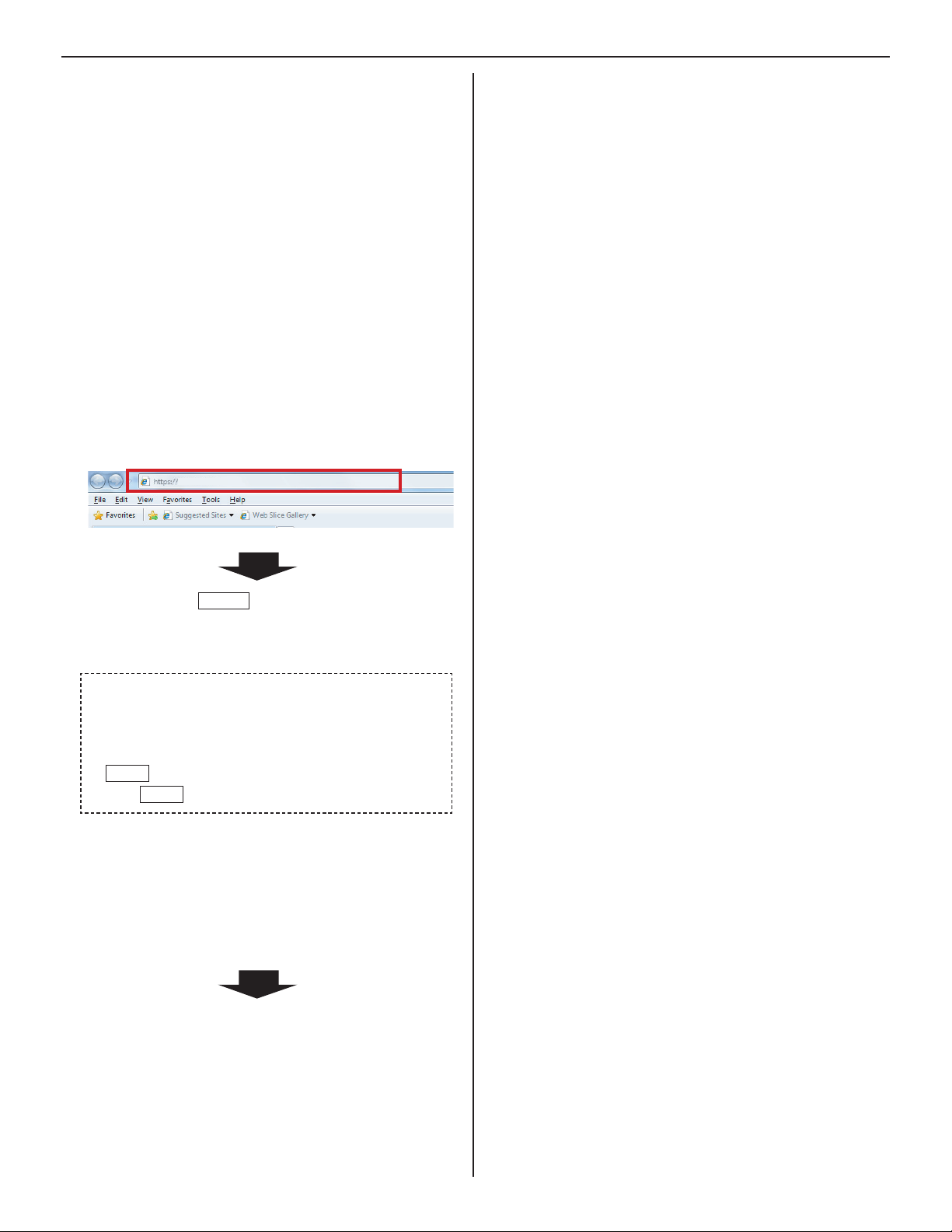
Start up the PC, and then open the browser window.
3
Enter the 4 (static) IP address assigned to the IP unit
to access the web browser for settings.
Default: https://192.168.0.40
192.168.0.40/
After selecting
window of the web browser is displayed.
Log in to the system by setting the following items.
5
ID
•
Enter “aiphone”.
Password
•
Enter “aiphone”.
Login
•
Login
Click
*
When you log in for the fi rst time, the [
window appears. Register your system as needed.
(When registering your system, if you use an IS-SOFT in
the system, enter the license key of the IS-SOFT.)
NOTE:
Be sure not to log in to the system more than once at the same
time by opening multiple browser windows on the PC.
English
to display the setting window.
the target language, the login
as
Registration]
Go to the next page.
14
Page 15

THE SYSTEM SETTING DETAILS
The basic setting procedure
When you have logged in to the system, the setting window appears. You can make the settings on this window.
*
Make sure to refer to the on-screen instructions and comments displayed on each window when you make the settings.
*
Depending on the PC and its OS or environment, the display may differ.
<Setting window example>
Setting contents display area
The setting items of the selected setting title and their
details are displayed here.
GETTING STARTED USING THE SYSTEM APPENDIX
SETTING THE SYSTEM
Table of contents
The setting titles are listed here.
Click the title on which you want
to make the settings to display the
corresponding setting window.
NOTE:
The setting titles not required for a
network direct system are also grayed
out.
Instructions area
The instructions for settings are
displayed here.
Temporarily stored
Click this to save the current setting results
temporarily.
This temporary storing will not update the *
system with the new setting results. To update
the system, click the title “Updating the system”
and follow the necessary procedure.
The setting procedure
Click a title in the table of contents on which you wish to make the settings.
1
The setting window of the title is displayed.
Make the settings on the setting items individually.
2
When you have fi nished making the settings on the current window, click
3
Temporarily stored
to save the setting
results temporarily.
*
If you wish to cancel the setting results you have made, click a title in the table of contents or “Refresh” in the web browser
menu. (If you change the current window to another without storing the setting results temporarily, a pop-up window appears
asking if you want to store the results temporarily or not.)
Repeat step 4 1 to 3 to make the settings on the other titles.
To log out of the system, click [* Logout] in the table of contents.
15
Page 16

The following shows the setting procedure for the items of each title.
Refer to “SETTING LIST” (→P. 4-7) for details about the settings. Make the settings by also referring to the on-screen instructions.
Making network settings to each IP unit
[Network setting: Individual]
Make the settings for network to each IP unit connected
to the system according to your requirements.
Network setting: Individual in the table of
Click
1
contents.
Make the settings on the following items displayed in
2
the setting window.
[Host unit setting]:
•
Set this unit as either “Host unit” or “Client unit”. When set to
“Client unit”, also enter the IP address of the IP host unit.
[System name]:
•
When “Host unit” is selected at [Host unit setting], it is
required to enter a name for this system.
Selecting the network setting method
Set a (static) IP address to this unit. Select the method for acquiring
a (static) IP address between [DHCP] and [Static IP Address].
[DHCP]:
•
Check this when you will acquire an IP address with DHCP
*
A DHCP server (or a router) is required to acquire an
IP address with DHCP. A router may not have the setup
function depending on some models. For information about
setting a router, see the instruction manual for the router.
[Static IP Address]:
•
Check this when you set the static IP address manually,
and then enter the static IP address suitable for the
network you are using, subnet mask, etc.
*
It is required to enter the static IP address and
subnet mask.
[Unit name]:
•
Enter a name for this unit.
* This name is used for searching for this unit in the
network. If not named, this unit is recognized only by
the unit (station) type and MAC address.
[Connection port], [Connection Password]:
•
Enter the port number for controlling communication and
the password for security. Use the same port number
and password among the IP host unit and IP client units
within the site.
NOTES:
•
The IP host unit must not have an IP address identical to the IP
address of a remote site’s IP host unit.
•
The items that cannot be entered or selected are grayed out.
Required
Required
When the settings on this window have fi nished, update
4
the system from [Updating the system]. (→P. 28)
Making network settings for the whole
system [Network setting: Common]
Make the network settings for the whole system on the
web browser of the IP host unit.
Click 1 Network setting: Common in the table of
contents.
Make the settings on the following items displayed in
2
the setting window.
[UPnP]:
•
If you do not use UPnP, set [UPnP] to OFF.
[Global IP address]:
•
.
When [UPnP] is set to OFF, enter the static global IP
address of the router for use in your site.
[Multicast address 1 – 5]:
•
Enter the multicast addresses for the following:
1: For sound communication for paging between sites
2: For sound communication for paging in your site
3: (Not available)
4: For video communication in your site
5: For video communication between sites
*
Do not use multicast addresses that overlap those of
other devices connected to the same network.
[Audio/video port]:
•
Enter the port numbers used for audio and video
communication.
*
Do not use port numbers that overlap those of other
devices connected to the same network.
Temporarily stored
Click
3
Required
Required
to save the current setting
results temporarily.
*
If you wish to cancel the setting results you have made,
click a title in the table of contents or “Refresh” in the
web browser menu.
3
Click
to save the current setting
Temporarily stored
results temporarily.
*
If you wish to cancel the setting results you have made,
click a title in the table of contents or “Refresh” in the
web browser menu.
16
Page 17

Setting the administrator ID and password
[Administrator setting]
We recommend that you change the administrator ID and
password from default to unique ones for security purposes.
*
This setting can be made to each of the IP units in your site.
*
“aiphone” is preset as the default for both ID and password.
Click 1 Administrator setting in the table of contents.
Make the settings on the following items displayed in
2
the setting window.
[New administrator ID]:
•
Enter the new ID.
[Current Password]:
•
Enter the current password.
Confi rming the IP units connected to the
system [IP unit search]
Before confi guring system wide settings, confi rm the IP
units are connected to the network, and set the network
setting for each IP unit using [IP unit search].
Click
1
2
3
IP unit search in the table of contents.
IP unit search
Click
All the IP units connected to the system are displayed in
the list.
*
If IP units are not displayed, repeat this step until
displayed.
.
Confi rm the “Station type”, “MAC address” and “Unit
name” of the IP units in the list.
GETTING STARTED USING THE SYSTEM APPENDIX
SETTING THE SYSTEM
[New Password]:
•
Enter a new password.
[New Password (Re-type)]:
•
Enter the new password again.
Temporarily stored
3
Click
to save the current setting
results temporarily.
*
If you wish to cancel the setting results you have made,
click a title in the table of contents or “Refresh” in the
web browser menu.
NOTE:
The system administrator must keep the ID and password without
fail. If you forget the ID and password, you must initialize the unit,
thus all the setting contents return to default.
To make or change settings to an IP unit,
4
check the box for the target IP unit and click
Open the setting window
Another window opens. You can make settings for the
target IP unit individually.
Close the window.
5
Repeat step * 3 to 5 to make settings to other IP units.
NOTES:
•
This procedure cannot search for PC master stations (IS-SOFT)
and it is not a system failure. To add a PC master station (IS-SOFT)
in the system, install the application (IS-SOFT) to a PC before
connecting it to the network and see page 19.
•
It may be required to log in to open the setting window, and update
the system at [
Updating the system
.
(→P. 16)
] before closing the window.
17
Page 18

Registering areas and remote sites
[System setting – Area/Site registration]
Required
Register areas (for separating stations in your site) and/
or remote sites. The number to which a name is entered is
registered as an area or site number. Up to 99 areas and/or
sites (up to 31 for sites only) can be registered.
Click 1 Area/Site registration in the table of contents.
Enter an area name in the cell for the area number 01.
2
*
Be sure to enter an area name. A site cannot be
registered to the number 01.
*
The fi gures under
or site numbers.
Enter area and/or site names in the cells for other
3
numbers to register more areas and/or sites.
Select “Area” or “Site” from the pull-down menu of “Area/
•
Site”.
For a site, enter the IP address (global IP address of the
•
target site), port number and connection password for
the target site.
For a site, set “Door release” to enable (ON) or disable
•
(OFF) the door release action from the target site.
“Number” in the tables means the area
Registering zones
[System setting – Zone registration]
Register zones for paging (transmitting announcements) in
your site. The number to which a name is entered is registered
as a zone number. Up to 99 zones can be registered.
* Zones are groups of stations designated for paging.
Click 1 Zone registration in the table of contents.
Enter a zone name in the cell for the target zone
2
number.
*
The fi gures under "Number" in the table means the zone
number.
Enter zone names in the cells for other numbers to
3
register more zones.
Temporarily stored
Click
4
results temporarily.
*
If you wish to cancel the setting results you have made,
click a title in the table of contents or “Refresh” in the
web browser menu.
to save the current setting
4
Click
to save the current setting
Temporarily stored
results temporarily.
*
If you wish to cancel the setting results you have made,
click a title in the table of contents or “Refresh” in the
web browser menu.
NOTES:
•
Be sure to register at least one area to the area number 01.
(“1” is entered in the cell for the area number 01 as default.)
•
A call number displayed on the master station monitor consists of
an area number plus a station number (when called from within
your site).
18
Page 19
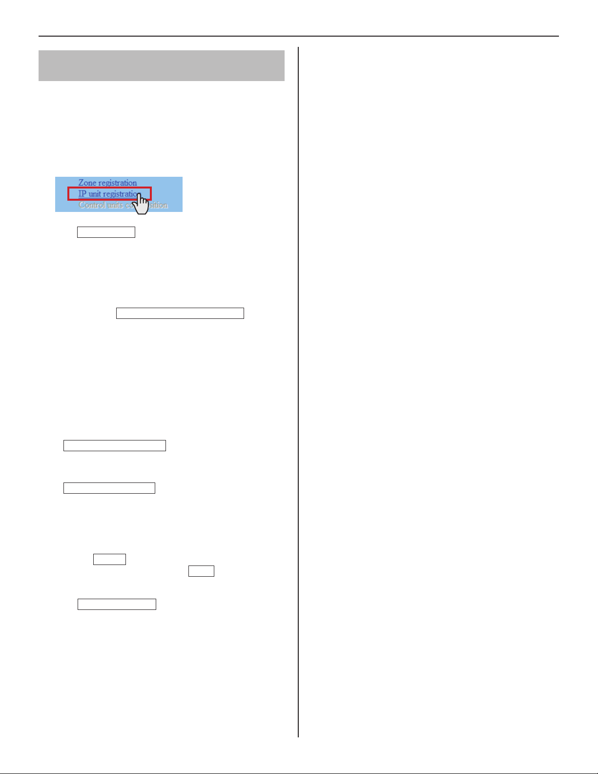
Registering IP units [System setting – IP
unit registration]
Register IP units by selecting from the connected ones to the
system.
*
To register a PC master station, fi rst install the application
(IS-SOFT) to a PC, then connect the PC to the network and
then start IS-SOFT.
Click 1 IP unit registration in the table of contents.
IP unit search
Click
2
All the IP units connected to the system are displayed in
the [Search result] on the lower side of the window.
*
If IP units are not displayed, repeat this step until
displayed.
Check the boxes for the IP units you want to register,
3
and then click
The checked IP units are registered and displayed in
[Imported IP units list] on the upper side of the window.
.
Add to the imported IP units list
.
GETTING STARTED USING THE SYSTEM APPENDIX
SETTING THE SYSTEM
Enter data or change settings for the registered IP
4
units as needed.
*
For "Port number", the sequential numbers are
automatically assigned as needed. (You can also enter
port numbers manually.)
*
Do not use port numbers that overlap those of other
devices connected to the same network.
Port number auto-setting
•
Click this to assign sequential port numbers
automatically.
Port forwarding setting
•
Click this and you can confi rm the port forwarding
settings to be made on the router in another window.
*
If [UPnP] is set to OFF at
Common], make the port forwarding setting on the
router with the set contents in this window manually.
Reload
Click
port forward setting, and click
window.
Temporarily stored
on this window to update the current
5
*
Click
:
:
[Network setting:
Close
to close this
to save the current setting
results temporarily.
*
If you wish to cancel the setting results you have made,
click a title in the table of contents or “Refresh” in the
web browser menu.
NOTE:
A PC master station must be also registered as an IP unit. First
install the application (IS-SOFT) to a PC, then connect the PC to the
network and then register it.
19
Page 20

Registering stations
[System setting – Registering stations]
Register all the stations connected in the system, and set the
area, station no. and station name to them.
Click 1 Registering stations in the table of contents.
Set the area, station no. and station name to the
2
target stations.
*
Setting the station no. is required to register the
station to the system.
How to select multiple stations
○ Click to check the stations you will register.
○ By clicking the button on the top of the list, you can
check or cancel all the stations on the list.
*
For a cell with the
pull-down menu.
*
Do not set stations with the same number in an area.
NOTE:
The name of a master station displayed on its monitor in standby
mode is up to 16 alphanumeric characters.
mark, select the target one from the
Other buttons
Connection check
•
Click to confi rm the connected units.
Connected: yellowish green
Not connected: gray
Station type error: pink
[Collective setting]:
•
The following buttons are used to make the settings to all
the checked stations at one time.
*
Pressing each button opens another window.
NOTE:
Be sure to check all the target stations before using these
buttons.
Area
•
Click to set the same area number to all the checked
stations.
3
Click
to save the current setting
Temporarily stored
results temporarily.
*
If you wish to cancel the setting results you have made,
click a title in the table of contents or “Refresh” in the
web browser menu.
Station number
•
Click to assign sequential numbers to all the checked
stations from top to bottom. The number you enter will
be set as the fi rst number and will be assigned to the top
station of the ones checked. Other checked stations will
be numbered sequentially.
Station name
•
Click to assign the same station name and sequential
numbers to all the checked stations from the top down.
Enter a name only.
Station type
•
(Not available in a network direct system.)
20
Page 21

Making detailed settings to stations
[System setting – Advanced station settings]
Make detailed settings for the registered stations. The settings
can be made to a station individually, or multiple stations of the
same type at a time. The setting items differ from the station
type. First select a station (or stations), and then open the
“Advanced settings” window to make the settings.
Making detailed settings to door
stations
GETTING STARTED USING THE SYSTEM APPENDIX
The following setting item buttons are displayed in the
“Advanced settings” window.
A
Basic setting procedure
Click Advanced station settings in the table of
contents.
Click to check the station(s) where detailed settings are
to be made.
*
Multiple stations of the same type can be set together.
*
All stations of the same type can be selected by clicking the
corresponding button under [Select all by type].
Advanced settings
Click
The “Advanced settings” window for the selected station type
opens.
.
B
*
Click either the button
corresponding setting window, and then make the
settings in the displayed window(s). See the detailed
instructions for
*
A
Settings on [Called stations] setting window
Set the master station(s) in your site and/or a remote site
that is (are) to be called from the selected station(s).
*
Up to 20 master stations in your site can be set. Or up to
19 master stations in your site and a remote site (up to 20
master stations are to be set at the remote site) can be set.
Select the “Call priority” from the pull-down menu.
1
Close
Click
the previous window.
to close the current window and return to
A
A
or B below.
or
B
to open the
SETTING THE SYSTEM
Make the settings in the displayed windows.
For door stations
The right column of this page
For master stations
P.22
When you have fi nished making all the detailed settings:
Temporarily stored
Click
to save the current setting
results temporarily.
*
If you wish to cancel the setting results you have made, click
a title in the table of contents or “Refresh” in the web browser
menu.
Reference
Click
2
the target master stations, and then click
to open another window, then check
Close
return to the previous window.
The selected master stations are added and displayed in
the list.
*
Click
Remote sites
selecting the remote site as the target to be called from
the selected station(s).
*
To delete a station (or stations) and/or remote site from
the list, check the targets in the list and click
to open another window for
Delete
Repeat step 3 2 to add more master stations.
4
Click
to close the current window and return to
Close
the previous window.
to
.
21
Page 22

B
Settings on [Other] window
[Transmit volume boost at PTT]:
•
Select whether to increase the press-to-talk sound
volume transmitted to the stations (ON) or not (OFF).
[Camera zoom image preset]:
•
Select the default of camera’s Zoom/Wide function at
calling from the 9 zoom positions and "0" (wide) from the
pull-down menu.
[Call acknowledge tone on/off]:
•
Select whether to sound the call acknowledge tone of
door station (ON) or not (OFF).
[Backlight adjustment]:
•
Select the method of adjusting the backlight in the
daytime between “Exposure +” and “Exposure –”.
Close
•
Click this to close the current window and return to the
previous window.
About the priority
The order of priority for actions (communication, calling, paging,
monitoring, etc.) is as follows depending on the priority setting.
Priority Setting Action
1 (high) [Urgent], [Broadcast] Communication, calling,
2 [Priority]
3 [Normal]
4 (low) - Monitoring, scan-monitoring
paging
Making detailed settings to master
stations
The following setting item buttons are displayed in the
“Advanced settings” window.
C
D
*
Click either the button
corresponding setting window, and then make the
settings in the displayed window(s). See the detailed
instructions for
*
C
Settings on [Stations to be scan monitored]
Close
Click
the previous window.
to close the current window and return to
window
Set the scan-monitoring target sub station(s).
*
Up to 20 sub stations in your site can be set.
Reference
1
Click
to open another window, then select
the target stations, and then click
the previous window.
The selected stations are added and displayed in the
list.
*
To delete a station (or stations) from the list, check the
target station(s) in the list and click
C
or D below.
C
or D to open the
Close
to return to
Delete
.
Repeat step 2 1 to register more stations.
3
Click
to close the current window and return to
Close
the previous window.
D
Settings on [Other] window
[Master station function: paging, chime, monitor,
•
door release, and remote site call]:
Select whether to enable the following functions of
master station (ON) or not (OFF).
Starting paging
•
Starting chime paging (Not available)
•
Monitoring/scan-monitoring
•
Releasing door
•
Remote site call
•
Close
•
Click this to close the current window and return to the
previous window.
22
Page 23

Registering stations to zones
[
System setting – Zone setting]
Assign stations to the registered zones.
Click 1 Zone setting in the table of contents.
Registering daily transfer schedule
[Transfer setting – Registering daily
transfer schedule]
You can set the schedule for transferring calls to other
master stations in your site or remote sites automatically. The
schedules registered on this setting are used when making a
transfer setting on a master station.
Up to 2 daily schedules can be registered.
GETTING STARTED USING THE SYSTEM APPENDIX
Select a zone from the pull-down menu.
2
Reference
Click
3
in your site.
Another window opens and the registered stations are
displayed in the list.
Check to select the target stations.
4
Select stations in the following ways.
Select stations by checking one by one.
•
All stations of the same type can be selected by
•
clicking the corresponding button under [Select all by
type].
By clicking the button on the top of the list, all the
•
stations are checked or canceled.
to display all the registered stations
Click 1 Registering daily transfer schedule in the
table of contents.
[Schedule number]:
2
Select the schedule number DT1 or DT2 from the
pull-down menu.
[Schedule name]:
3
Enter the name of daily schedule.
[Call transfer time]:
4
Set the [Start time (hour and minute)] and [End time
(hour and minute)] of transferring.
Temporarily stored
Click
5
results temporarily.
*
If you wish to cancel the setting results you have made,
click a title in the table of contents or “Refresh” in the
web browser menu.
to save the current setting
SETTING THE SYSTEM
Close
Click
5
stations.
In the previous window, the selection results are displayed
in the list.
*
When canceling a registered station, check the station in
the list, then click
Click
6
results temporarily.
*
If you wish to cancel the setting results you have made,
click a title in the table of contents or “Refresh” in the
web browser menu.
after you have fi nished selecting the
Delete
Temporarily stored
.
to save the current setting
23
Page 24

Setting transfer schedule
[Transfer setting – Transfer schedule setting]
You can set a weekly transfer schedule and individual daily
schedule.
*
The settings can be made 1 year ahead.
Click 1 Transfer schedule setting in the table of
contents.
Make the settings by clicking
2
Individual schedule
and
corresponding window.
respectively to open the
Weekly schedule
E
Settings on [Weekly schedule] setting window
Select either [Every week] or [Every other week].
1)
Set the schedule start and end dates.
2)
*
The monthly calendar is displayed by clicking
Refer calendar
end dates.
*
If necessary, you can change the month by clicking
or .
Set one of the registered daily transfer schedules or no
3)
schedule to each day of the week. (Select one from the
pull-down menu.)
and you can select the start and
E
F
Individual schedule
*
date is clicked on the calendar.
Make the settings in the displayed window(s).
3
See the detailed instructions for E or F on the
right column of this page.
After the setting is fi nished on the corresponding
4
window, click
Calendar and setting status can be checked for the
selected month.
The registered daily transfer schedules are
identifi ed by colors and shown on the calendar.
should be clicked after the target
Close
to close the window.
F
Settings on [Individual schedule] setting window
Set an individual schedule to the target date.
*
[Individual schedule] setting window will not open if you
have not selected the target date on the calendar in the
[Transfer schedule setting] window.
If necessary, you can change the date by clicking
1)
repeatedly.
[Daily transfer schedule]:
2)
Select either of the registered daily schedules (DT1 or
DT2) or no schedule from the pull-down menu.
[Call transfer time]:
3)
When “DT1” or “DT2” is selected:
•
The call transfer time is automatically entered.
If necessary, change the [Start time (hour and
minute)] and [End time (hour and minute)] of
transferring manually.
When no schedule is selected:
•
Enter the call transfer time manually.
*
When the time is entered or changed manually, [Daily
transfer schedule] changes to “Individual schedule”.
or
5
Click
to save the current setting
Temporarily stored
results temporarily.
*
If you wish to cancel the setting results you have made,
click a title in the table of contents or “Refresh” in the
web browser menu.
When the settings on this window have fi nished, update
6
the system from [Updating the system]. (→P. 28)
24
Page 25

Setting the timer [Timer setting]
Set the time for each operation.
Click 1 Timer setting in the table of contents.
Set the time for the following operations respectively.
2
*
The setting range is displayed on the right side of each
input box.
[Call]:
•
Set the duration of call from door stations to [Normal],
[Priority] or [Urgent].
[Communication]:
•
Set the duration of communication between stations in
the system including between remote sites [Via IP].
*
[In Local] and [Telephone]: Not available in a network
direct system.
[Paging]:
•
Set the duration of paging.
[Monitor]:
•
Set the duration of monitoring only one station.
GETTING STARTED USING THE SYSTEM APPENDIX
SETTING THE SYSTEM
[Scan monitor: Switching]:
•
Set the duration of monitoring each station while scanmonitoring.
NOTE:
The actual duration slightly differs from the setting value.
[Contact output]:
•
(Not available)
[Door release]:
•
Set the duration of door release.
*
If you set the time to “0”, the door is released while
the door release button on the master station is held
down.
Temporarily stored
3
Click
to save the current setting
results temporarily.
*
If you wish to cancel the setting results you have made,
click a title in the table of contents or “Refresh” in the
web browser menu.
25
Page 26

Setting stations to receive calls and
zones to receive paging from remote sites
[Remote site pilot call setting]
Set the master stations and sub stations to receive calls, and
zones to receive paging from remote sites.
*
The setting can be made for each priority individually.
Click 1 Remote site pilot call setting in the table of
contents.
Make the setting by clicking
2
the setting items G, H, I respectively to open the
corresponding window.
G
H
*1
I
*2
Make the setting in the displayed window(s).
3
See the detailed instructions for
right column of this page.
After the setting is fi nished on the corresponding
4
window, click
Close
to close the window.
Advanced settings
G, H, I
on the
for
G
Settings on [Remote site master call] setting
window
You can set a station (master station or door station) that
receives a call from a master station in a remote site. One
station can be set for each priority.
Reference
Click
1)
All the registered stations are displayed in the list in
another window.
Check the box for the target station in the list, and then
2)
Close
click
The current window closes and the set station is
displayed in the [Remote site master call] setting
window.
for “Normal”.
.
To delete a set station
Delete
Click
*
Selecting another station also overwrites the previous
one.
Make the setting for “Priority” and “Urgent” in the same way.
Settings on [Remote site door call] setting
H
for "Normal".
window
You can set up to 20 master stations that receive a call
from a door station in a remote site. Up to 20 master
stations can be set for each priority.
Reference
Click
1)
All the registered master stations are displayed in the
list in another window.
Check the boxes for the target master stations in the
2)
list, and then click
The current window closes and the set stations are
displayed in the [Remote site door call] setting window.
for “Normal”.
Close
.
To delete a set station
Check the box for the target station and click
*
You can also select two or more stations and delete
them at a time.
Make the setting for “Priority” and “Urgent” in the same
way.
Delete
.
5
Temporarily stored
Click
to save the current setting
results temporarily.
*
If you wish to cancel the setting results you have made,
click a title in the table of contents or “Refresh” in the
web browser menu.
*1: The settings on this item are available for a call from the
standard (IP) system in a remote site. The setting method is
the same as the item H. (Refer to the “SETTING MANUAL”
for a standard (IP) system for details.)
*2: Not available
26
I
Settings on [Remote site paging] setting window
You can set a zone that receives paging from a remote
site. One zone can be set for each priority.
Select the target zone from the pull-down menu for
1)
“Normal”.
*
Make the setting for “Priority”,“Urgent”and “Broadcast”
in the same way.
Page 27

Video setting
Click 1 Video setting in the table of contents.
Set the following settings for video quality.
2
[Frame Rate]:
•
Set the frame rate selecting “1”, “2”, “5”, “7.5”, “10” or “15”
fps from the pull-down menu.
[Quality]:
•
Set the video quality selecting “Low”, “Middle”, “High” or
“Excellent” from the pull-down menu.
Temporarily stored
Click
3
results temporarily.
*
If you wish to cancel the setting results you have made,
click a title in the table of contents or “Refresh” in the
web browser menu.
NOTE:
Raising [
quality. Also, raising [
both [
amount of network bandwidth will be required.
Frame Rate
Frame Rate
] from 1 to 15 fps gives you a smoother image
Quality
] and [
Quality
to save the current setting
] gives you a fi ner image. However, if
] are raised at the same time, a large
Setting time and date
[Time and date setting]
Set the time and date of the system, used for transfer schedule.
Click 1 Time and date setting in the table of contents.
Set the following settings.
2
[Set current time]
•
Set the current time and date in one of the following
methods.
Input the current time and date manually, and then
•
•
•
*
Manual setting
click
Synchronized with PC
Click
and date by making it synchronized with the PC.
You can also set the current time and date by
synchronized with NTP server [Synchronized with NTP
server] as shown below.
If there is no power supply to the system for a long
time because of power failure etc., the time and date
setting may be cleared.
Required
.
:
to set the current time
GETTING STARTED USING THE SYSTEM APPENDIX
SETTING THE SYSTEM
making it
[NTP (Network Time Protocol)]:
•
Set [Synchronized with NTP server] to ON to set the
current time and date by making it synchronized with
NTP server. Then set the [NTP server] and [NTP port
number].
*
[NTP server]:
Enter the IP address or domain name of the NTP
server to be used as the master clock.
[UTC time zone]:
•
Set the time differences from Coordinated Universal
Time (UTC). Set the [Hour difference] and [Minute
difference] respectively.
[Synchronize interval]:
•
When [Synchronized with NTP server] is set to ON, the
current time and date are set by being synchronized
with the NTP server with the entered time interval.
[Daylight savings time]:
•
Set whether to utilize daylight savings time (ON) or
(OFF). When set to ON, then set the start and end
times (Month, Week of the month, Day of the week,
Hour and Minute), and time differences (Hour and
Minute).
*
It is recommended to connect the system with a PC or
NTP server constantly to keep the correct time and date
setting.
3
Click
to save the current setting
Temporarily stored
results temporarily.
*
If you wish to cancel the setting results you have made,
click a title in the table of contents or “Refresh” in the
web browser menu.
27
Page 28

E-mail setting
You can send an e-mail when calling or send error messages
etc. by e-mail. Up to 3 mail addresses can be set.
NOTES:
•
Prepare an e-mail account for this function beforehand.
•
Make sure to enter the system name at
Individual]
•
Make sure to enter primary and/or secondary DNS server
information at [
– [System name] to display the title with an e-mail.
Network setting: Individual
Click 1 E-mail setting in the table of contents.
Set the following settings.
2
[Email destination address]:
•
Enter up to 3 mail addresses (destination addresses).
[Email source address]:
•
Enter the source mail address.
[SMTP authentication]:
•
Confi gure SMTP authentication as required by source
E-mail provider.
[Language selection]:
•
Set the language you want to use for entering the system
name.
*
You can use English only for the body of the message.
[Network setting:
] to all the IP units.
Downloading/uploading setting data
[Setting fi le]
You can download the setting data you have made into a fi le
and save it on the PC. On the contrary, you can upload the
setting data from the PC.
*
It is recommended to download the setting data as a backup
copy after you fi nish making settings or setting changes.
When downloading setting data onto the PC
■
Click 1 Downloading setting data in the table of
contents.
Click
2
Download
into a fi le.
When uploading setting data
■
Click 1 Uploading setting data in the table of contents.
to download the current setting data
[Mailing event]:
•
Select mailing events by setting the target ones to [ON].
Temporarily stored
3
Click
to save the current setting
results temporarily.
*
If you wish to cancel the setting results you have made,
click a title in the table of contents or “Refresh” in the
web browser menu.
2
Click
Upload
to upload the setting data from the PC
to the system.
You can select the setting data fi le from another window,
and upload it.
Update the system.
3
*
Refer to “Updating the system” below.
NOTE:
Uploading the setting data will overwrite the current data.
Updating the system
[Updating the system]
Update the system with the setting data you have entered
(currently stored temporarily).
Click 1 Updating the system in the table of contents.
Click
2
Update
data currently stored temporarily.
to update the system with the setting
28
NOTE:
Do not turn off the system while updating the system.
Page 29

MAINTENANCE
This section describes the use of functions for the system maintenance. These functions are available on the web server.
Initializing the system [Initialization]
You can reset the system settings to factory default.
Access the web browser and log in.
1
(→P. 14)
Click
2
3
Initialization in the table of contents.
Click
Initialization
.
Downloading system log [System log]
You can acquire the system operation log.
Access the web browser and log in.
1
(→P. 14)
Click 2 System log in the table of contents.
Updating the fi rmware [Firmware update]
Downloading updated fi rmware data
■
Please access our web page at http://www.aiphone.net/ and
download the fi rmware data on the PC to update the system.
For the download procedure, see the instructions on our web
page.
Access the web browser and log in. (→P. 14)
1
Click 2 Firmware update in the table of contents.
Click
3
4
5
Update
Another window opens.
Click
Browse...
When the fi rmware is displayed in the window, click
Upload
When “Update fi rmware.” is displayed, the update process
is complete.
.
and select the target fi rmware.
.
GETTING STARTED USING THE SYSTEM APPENDIX
SETTING THE SYSTEM
Click
3
4
NOTE:
The log is overwritten constantly from the oldest records.
Download
Confi rm the log, and save it as needed.
to acquire the log from the system.
NOTES:
•
If the power is turned off while it is writing, the product will
malfunction.
•
The system may not operate normally while updating the
fi rmware.
NOTE:
If the update fails, try again.
Referring to the troubleshooting guide
[Troubleshooting]
Click 1 Troubleshooting in the table of contents.
The following information appears in the window.
Information about the online-help that you can refer to
•
when trouble occurs in setting the system
Supported characters and symbols
•
Registering your system [Registration]
Click 1 Registration in the table of contents.
Register
Click
2
then register your system on the window.
*
If you use an IS-SOFT in the system, enter the license
key of the IS-SOFT.
to open the registration window, and
29
Page 30

Setting Information Memo
Record your settings information. It will need when resetting or maintenance.
Host unit
Network setting: Individual
Static IP Address Subnet Mask
Default Gateway
Primary DNS Server Secondary DNS Server
MAC address
Unit name
Connection port Connection Password
Network setting: Common
Global IP address
Connection port: global
Multicast address 1: 2:
3: 4:
5:
Audio/video port
Administrator setting
ID Password
Client unit
Network setting: Individual / Administrator setting
# Unit name MAC address IP Address ID Password
1
2
3
4
5
6
7
8
9
10
11
12
13
14
15
16
17
18
19
20
21
22
23
24
25
26
27
28
29
30
31
* Download and save the setting data on the PC. Refer to [Setting fi le] for details.
30
Page 31

http://www.aiphone.net/
AIPHONE CO., LTD., NAGOYA, JAPAN
AIPHONE CORPORATION, BELLEVUE, WA, USA
AIPHONE S.A.S., LISSES-EVRY, FRANCE
 Loading...