

Page 1
www.aimshot.com
Night Vision
Amstech Incorporated
340 Dewpoint Lane
Alpharetta, GA 30022 U.S.A.
Tel: +1-770-840-8039 Fax: +1-770-840-0269
Email: [email protected]
0413
North America Distributor
Osprey International, Inc.
1124 Tennessee Street, Suite 101
Cartersville, GA 30121
Fax: +1-770-387-0114
Customer Service: +1-770-387-4342
Email: [email protected]
Made in Belarus
Packaged in the USA
NVS143
Page 2

Table Of Contents
ACCEPTANCE CERTIFICATE
Important Instructions …………………………..
Introduction ………………………………………
Specifications ……………………………………
Description ………………………………………
Prior To Operation ……………………………..
Mounting To Weapon ………………………….
Adjustments …………………………………….
Sight Adjustments ……………………………...
Operational Tips ………………………………..
Operation ………………………………………..
Trouble Shooting ……………………………….
Warranty …………………………………………
Acceptance Certificate …………………………
Please read this entire manual prior to operation of this device
(1)
Page 2
Page 3
Page 4
Page 5
Page 8
Page 9
Page 10
Page 11
Page 12
Page 13
Page 16
Page 17
Page 18
Night Vision Weapon Sight NVS143
The code: 470.00
Serial #_____________________
Stamp Production date_____________________
QC Representative__________________
Date of sale________________________
Fastenung bracket type
B63 (21,4мм) plank (Fig. 3)
Plank (8…15 мм)
Side plank Saiga t ype
Plank EVRO type
(Fig. 4)
(18)
Page 3

Warranty
Important Instructions
The manufacturer warrants its product to be free of defects in material
and workmanship for the duration of the warranty period. If the product
proves to be defective in material or workmanship during the warranty
period, the manufacturer will at its sole option repair or replace the
product with a like product.
The NVS143 warranty period is 1 year from the date of purchase by an
end user.
The warranty is only valid for the purchaser and is nontransferable.
The warranty does not cover any product on which the serial number
has been defaced, modified or removed. Damage, deterioration or malfunction resulting from accident, misuse, neglect, modification of the
NVS143, acts of nature, or failure to follow instructions supplied with the
product.
This warranty will be voided if the NVS143 have been disassembled in
any way.
(17)
Read all instructions prior to operation.
Do not use this sight in daylight with the lens cover removed, damage
may occur to the unit.
Avoid aiming this sight towards bright light sources.
Avoid rotation of ranging unit flywheels above the setting range of the
sight line corrections.
Keep the sight out of direct ingress of water.
Do not attempt to disassemble this device- the warranty will be voided.
If any problems occur contact the manufacturer.
Use only a damp cloth to clean the housing and lens tissue to clean
the optics.
Always handle with care, avoid shocks, dust and debris.
If yourNVS143 is not working properly, please use the following trouble
shooting tips.
(2)
Page 4

Introduction
Trouble Shooting
Thank you for purchasing the NVS143 night vision weapon
sight.
The following items should be included in the package:
• NVS143 Night Weapon Sight
• Carry Case
• Manual
• IR Searchlight (optional)
This night vision sight is designed for hunting in low light and
nighttime conditions. The NVS143 based on image intensifier tube
EP33U (B8U) type (Gen. 1). It can be equipped with IR searchlight to operate in complete darkness (optional). Please avoid
aiming at bright light sources during the operation. Please practice weapon safety at all times.
(3)
If your NVS143 is not working properly, please use the following
trouble shooting tips.
No Picture:
Check to make sure that the power switch is in the on position.
Check to see that the lens cover is off.
Replace the batteries.
Dark Picture:
Replace the batteries.
Low ambient light level.
Turn on the IR searchlight.
Move into higher ambient light.
Black Spots:
Normal for all night vision and does not effect viewing or performance.
(16)
Page 5
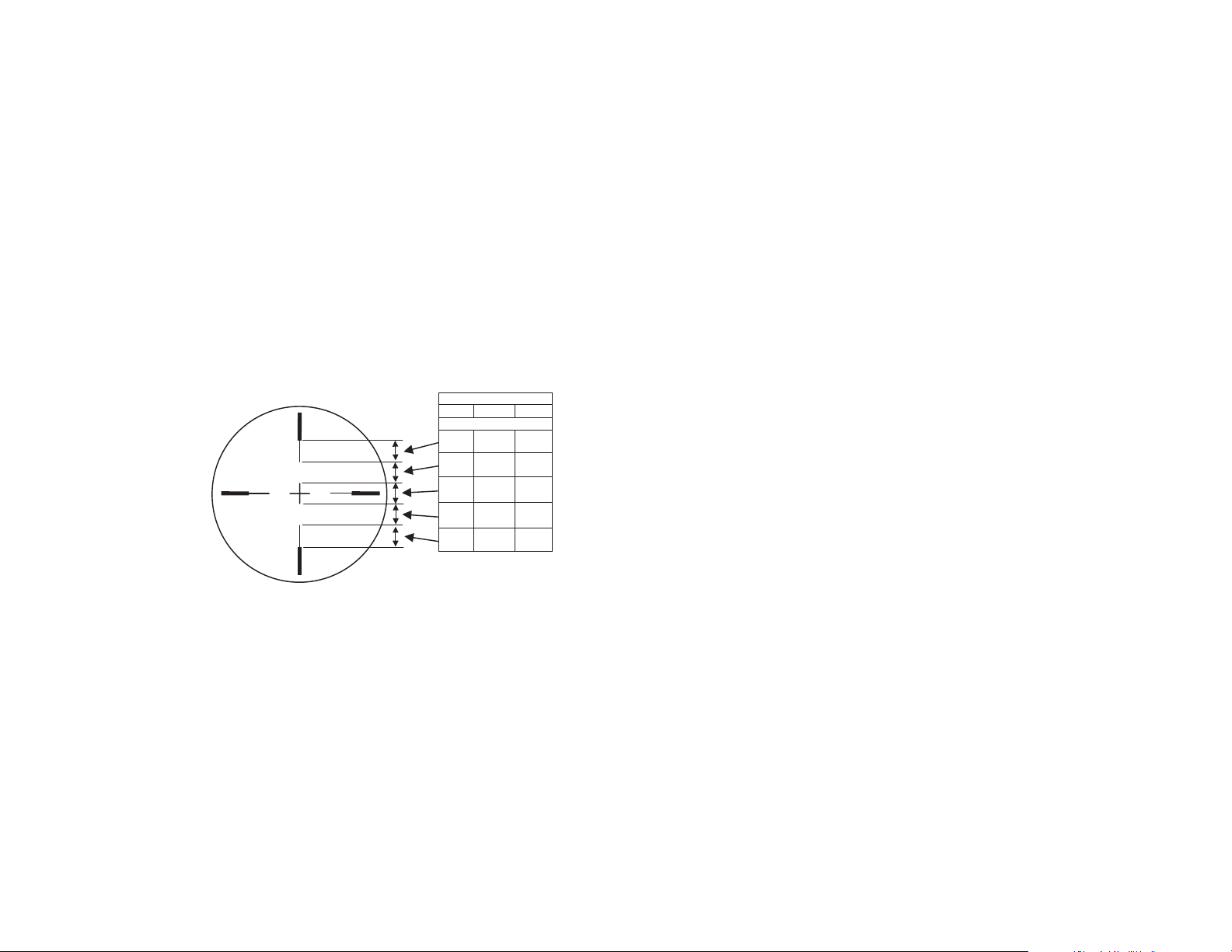
The sighting mark and a target sizes correlation
Table 2
Distance, m
50 100 200
Ta±get sizes, m
0,5 1 2
0,5 1 2
0,5 1 2
0,5 1 2
0,5 1 2
Specifications
Magnification 3х
Field Of View 12°
Min. Focus Distance 5 meters
Target detecting range:
At the moonlight (1/4 moon) 200 m
In complete darkness (IR searchlight is on) 80…110 m
Sight Mark Adj. Range
at 50m Distance ± 1 m
at 100m Distance ± 2 m
Co±±ections mechanism scale division:
- 50m Distance 15 mm
- 100m Distance 30 mm
Powe± Supply (CR123A Lithium batte±y) 3v
Batte±y Life 36 h±s.
Dimensions 220x80x100 mm
Weight 0,85 kg
(15)
(4)
Page 6
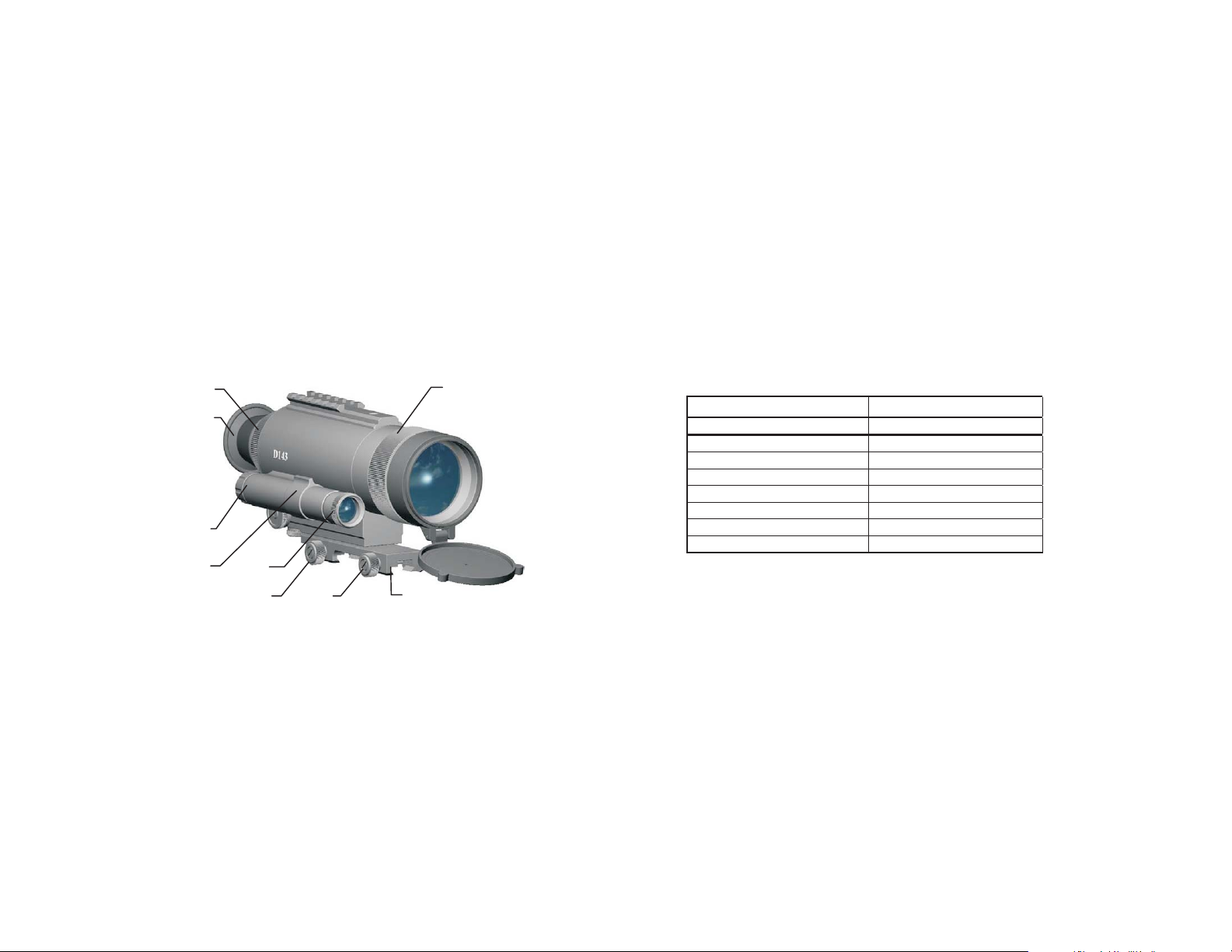
Description
A General View of the NVS143
2
3
9
5
4
1
Illumination Rates
Table 1
Conditions Illumination, lux
Moonless night 0,01
¼ moon 0,05
Moon 0,3
Deep twilight 1,0
Twilight 10
Cloudy day 500
Some clouds 5 000
No clouds 50 000
(5)
11
11
10
Figure 1
(14)
Page 7
Operation
Description
• Switch on the NVS143 with the rotary switch (5) (fig.1).
• Aim the NVS143 safely at an object. Adjust focus rings (1) and (2)
(fig. 1)
• Switch on the IR Searchlight if necessary with the rotary switch
(5) (fig.1) by turning it to IR position.
Warning! Setting of the high brightness level for a long time
can damage the intensifier tube!
• Switch off the NVS141 when finished with operation. Always place
the lens cap back on the unit prior to storage to protect the objective lens.
Always practice weapon safety.
(13)
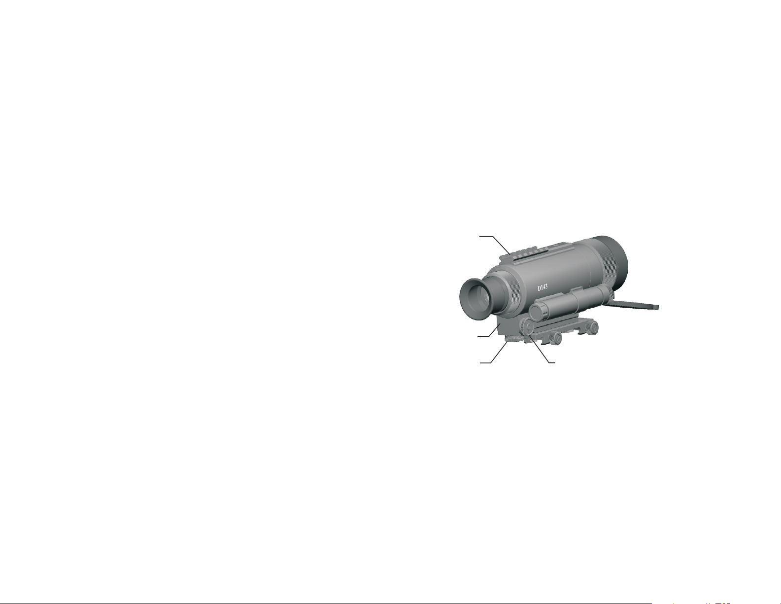
12
6
8
7
Figure 2
(6)
Page 8

Description
Operational Tips
1 Lens Focusing Ring
2 Eyepiece Focusing Ring
3 Eye Shield
4 IR Searchlight
5 Power ON/OFF Switch
6 Correction Mechanism
7 Horizontal Corrections Mechanism
8 Vertical Corrections Mechanism
9 Battery Compartment Cover
10 Fastening Bracket
11 Fastening Bracket Fixing Screws
12 Additional external units fastening plank
(7)
Never turn the sight on in daytime or under the luminance
upper than 5 lux (see table 1) without the lens cover attached to the front lens, damage may occur to the image
tube if it is exposed to bright light sources.
Make sure that the device is attached firmly to your weapon
base prior to taking a shot.
(12)
Page 9
Sight Adjustments
To adjust proceed as follows:
- Set the weapon with the NVS143 on a solid base
- Take off the lens cover
- Turn the Sight ON with the switch (5) (fig.1)
- Set the sighting mark to the center position by turning correction
mechanisms flywheels (fig.6)
- Perform ranging the weapon by shifting the sighting mark position using flywheels to align it with the firing line of your weapon
- Make the control shot
- Turn off the Sight and replace the lens cover
(11)
Prior To Operation
Battery Installation:
Check the lens cover to make sure it is attached.
Check the power ON/OFF switch (5) (fig.1) to be in the OFF position.
Remove the battery compartment cover (9) (fig.1)
Install battery CR 123A into the compartment and replace cover.
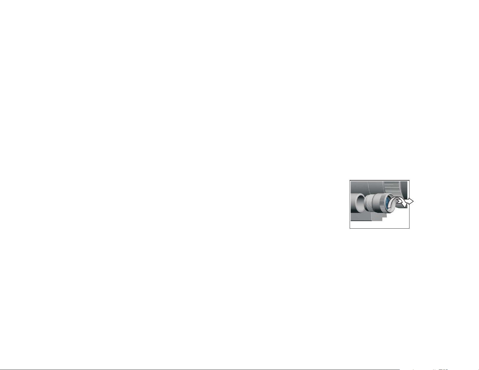
IR Searchlight Installation
The Sight is equipped with LED based
IR Searchlight. Laser-based one can be
placed instead. Simply screw out the IR
searchlight (counterclockwise) and
screw in another one instead (Fig. 3).
Check Operation
Once pre operation is complete test the
unit in a lit room with the daylight cover
attached.
Figure 3
(8)
Page 10
Mounting To Weapon
Weapon Fastening:
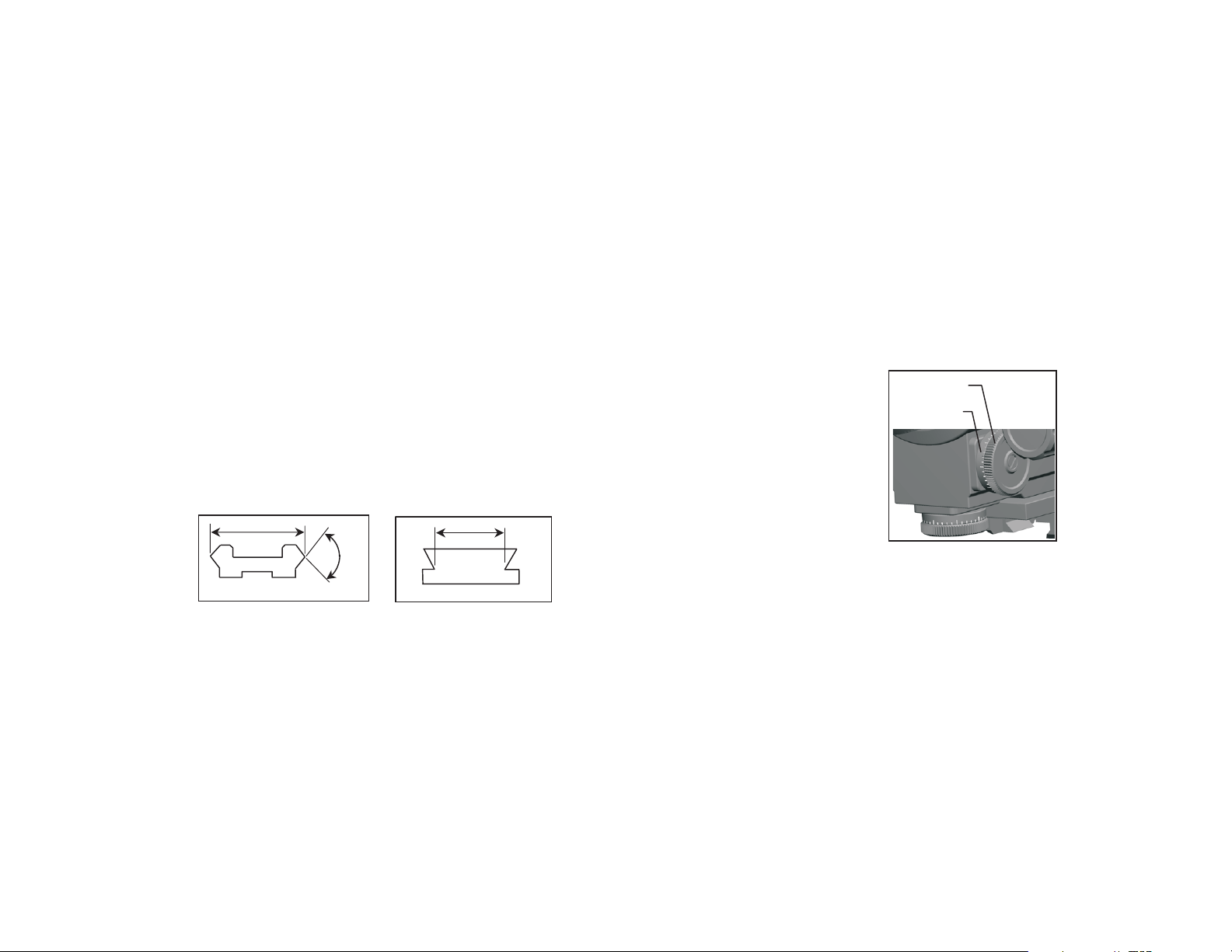
The NVS143 can be equipped with one the following fastening brackets (10)
(fig.1):
- fastening bracket, which have the mounting dimensions of a standard
weaver base 63B (21,4 mm) (fig. 4);
- 8…15 mm plank type bracket (fig.5);
- side plank Saiga type;
- plank EVRO type.
Your base must be firmly fastened to your weapon prior to attaching the D143
weapon sight.
Tighten the bracket screws (11) (fig.1).
21,4
90°
8…15
Adjustments
Sighting Line Adjustment:
The botton corrections mechanism (6)
(fig.1) body incorporates vertical
corrections mechanism (8) to move
the sighting mark up and dawn. The
horizontal corrections mechanism (7)
is in the side of the corrections
mechanism body. The sighting mark
moves left and right.
Flywheel
Scal
Рис. 5
Figure 6
Figu±e 4
(9)
Figu±e 5
(10)
 Loading...