

Page 1
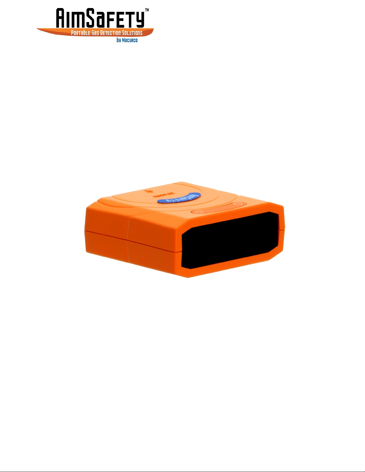
AimSafety™ PM Link
PC Interface for PM
User Instructions
and PM
100
Gas Monitors
400
IMPORTANT: Keep these user instructions for reference.
Page 2

PM Link User Manual
1 Driver and Software Installation ............................................................................................................................... 4
1.1 Download and Install Drivers ........................................................................................................................... 4
1.2 Download and Install the PM Link Software .................................................................................................... 4
2 Operation and User Interface ................................................................................................................................... 8
2.1 Connect the PM Link Hardware to The Computer ........................................................................................... 8
2.2 Launch the Software ......................................................................................................................................... 8
2.3 Open the PM Link COM Port ............................................................................................................................ 9
2.4 Read a PM monitor ......................................................................................................................................... 10
3 PM Monitor Configuration ..................................................................................................................................... 12
3.1 Load A Configuration ...................................................................................................................................... 13
3.1.1 Read the Current Configuration from a PM monitor ............................................................................. 13
3.1.2 Load a Previously Saved Configuration File ............................................................................................ 13
3.2 PM
Configuration Options .......................................................................................................................... 13
100
3.2.1 User Id/Message: .................................................................................................................................... 13
3.2.2 Display .................................................................................................................................................... 14
3.2.3 Stealth ..................................................................................................................................................... 14
3.2.4 Self-Test .................................................................................................................................................. 15
3.2.5 Low Alarm ............................................................................................................................................... 16
3.2.6 High Alarm .............................................................................................................................................. 16
3.2.7 Cal (Calibration) Concentration .............................................................................................................. 17
3.2.8 Cal Time (sec) .......................................................................................................................................... 18
3.2.9 Cal Interval (day) ..................................................................................................................................... 18
3.2.10 Bump Interval (day) ................................................................................................................................ 19
3.3 PM
Configuration Options .......................................................................................................................... 19
400
3.3.1 Basic Options .......................................................................................................................................... 20
3.3.2 Advanced Options .................................................................................................................................. 22
3.3.3 Check Options ......................................................................................................................................... 23
3.4 Write the New Configuration to the PM Monitor .......................................................................................... 24
3.5 Save a Configuration to File ............................................................................................................................ 25
4 PM100/400 Calibration .......................................................................................................................................... 25
4.1 Zero Calibration .............................................................................................................................................. 26
4.2 Span Calibration ............................................................................................................................................. 27
5 Firmware Upgrade .................................................................................................................................................. 30
6 Logging .................................................................................................................................................................... 31
6.1 PM
Logs ....................................................................................................................................................... 32
100
6.1.1 View Log Data ......................................................................................................................................... 32
6.1.2 Erase Log Data ........................................................................................................................................ 33
6.2 PM
6.2.1 Download Log File ................................................................................................................................
Logs ....................................................................................................................................................... 33
400
.. 33
6.2.2 View Log Files ......................................................................................................................................... 35
6.2.3 Erase Log Data ........................................................................................................................................ 37
7 Product limited warranty ....................................................................................................................................... 38
Technical Support Contact Information ....................................................................................................................... 38
General Contact Information ........................................................................................................................................ 38
REV – 1.0 [34-2900-0510-4] 2 | Page
Page 3

PM Link User Manual
REV – 1.0 [34-2900-0510-4] 3 | Page
Page 4

PM Link User Manual
1 Driver and Software Installation
1.1 Download and Install Drivers
Users of Windows 8 or above should be able to skip this step and proceed directly to Section 1.2.
To download the drivers:
1. Go to http://macurco.com/products/aimsafety/
32-bit vs. 64-bit.
NOTE: If the version is unknown, choose the 32-bit version.
2. Save the installer to a folder where you will be able to find it when the download is finished. Your
Downloads folder or the desktop are good options.
3. When the download is finished, double-click the installer to begin installation.
and choose the appropriate version the operating system.
1.2 Download and Install the PM Link Software
To Download the Software:
1. Go to https://macurco.com/downloads/
“AimSafety_PM Link_v1.6.9_Install.exe.”
NOTE: “v1.6.9” is the version number of the software. The version may differ (example: v1.7.2).
2. When presented with the option to save or run the file, choose Save.
3. Save the installer to a folder where you will be able to find it when the download is finished. Your
Downloads folder or the Desktop are common options.
4. When the download is complete, the software is ready to be installed.
and choose the installer file. The installer file should look like
To Install the Software:
IMPORTANT: At certain points during the installation procedure, Windows may ask to allow the software to make
changes to the computer. Click Yes for these messages.
1. Locate the installer that was downloaded and double-click the icon to begin installation.
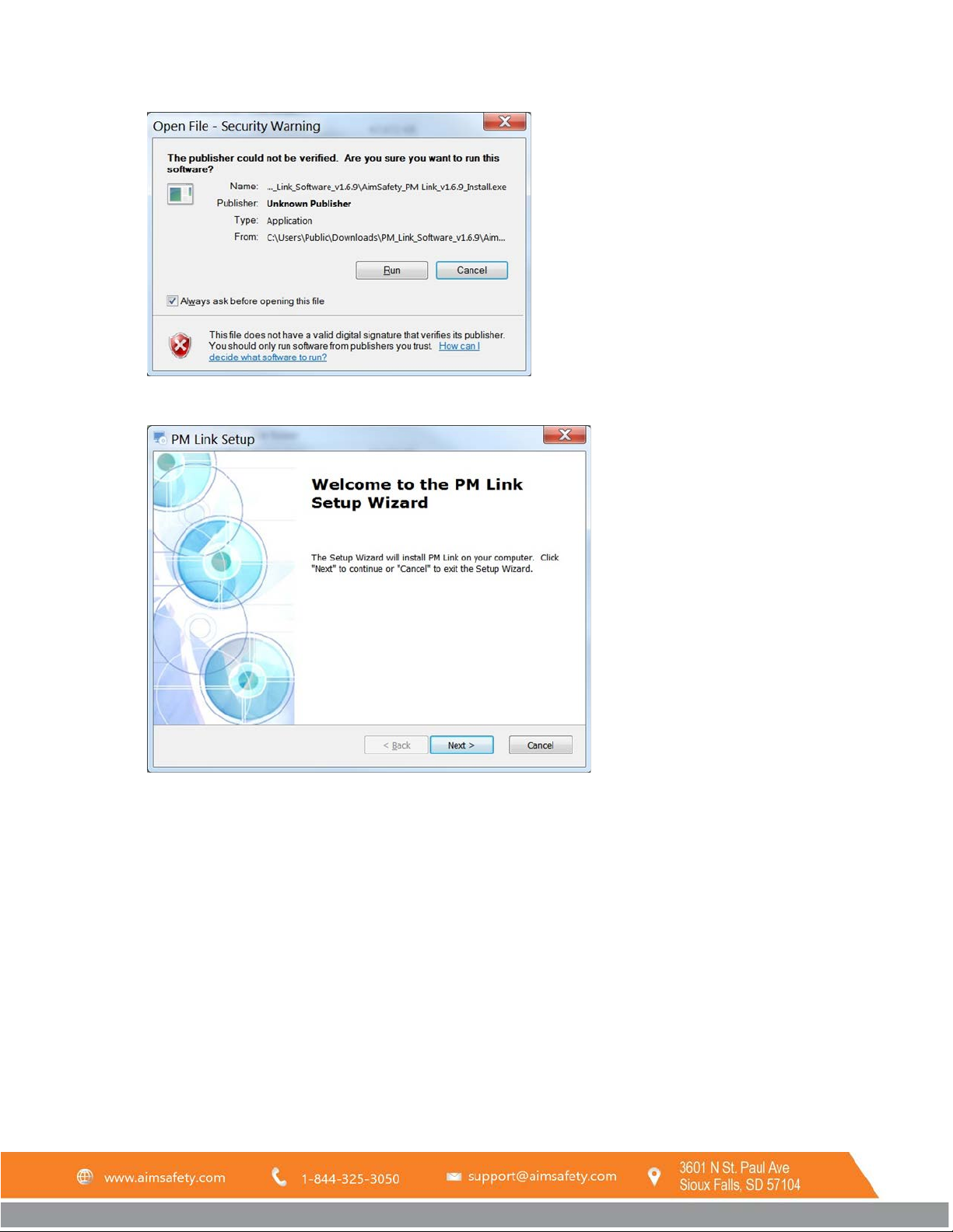
NOTE: You may receive a security warning (as shown below) about installing the software, click Run or Run
Anyway.
REV – 1.0 [34-2900-0510-4] 4 | Page
Page 5
PM Link User Manual
2. The PM Link Setup Wizard will start. Click Next.
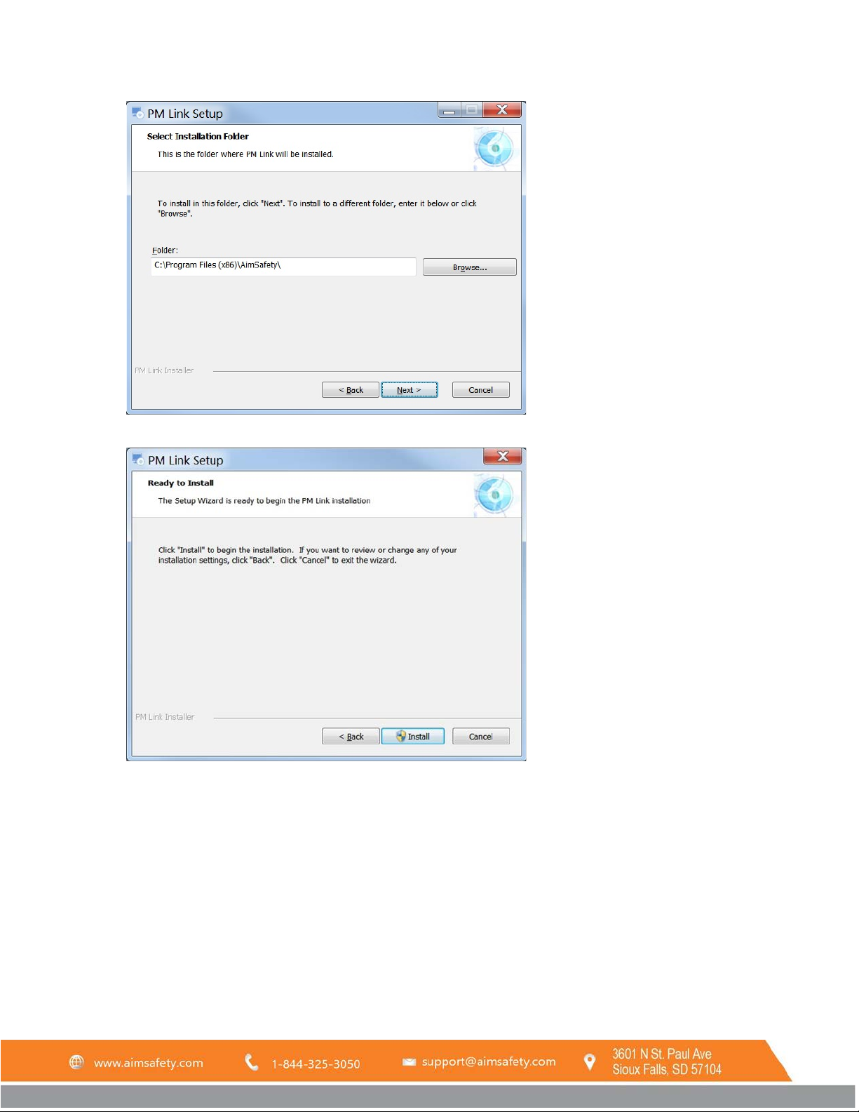
3. When the Select Installation Folder window displays, we recommend that you accept the default location
unless instructed differently by your system administrator. Click Next to use the default location. To change
the installation folder, click Browse and choose the location you want.
REV – 1.0 [34-2900-0510-4] 5 | Page
Page 6
PM Link User Manual
4. The Begin Installation screen displays. Click Install.
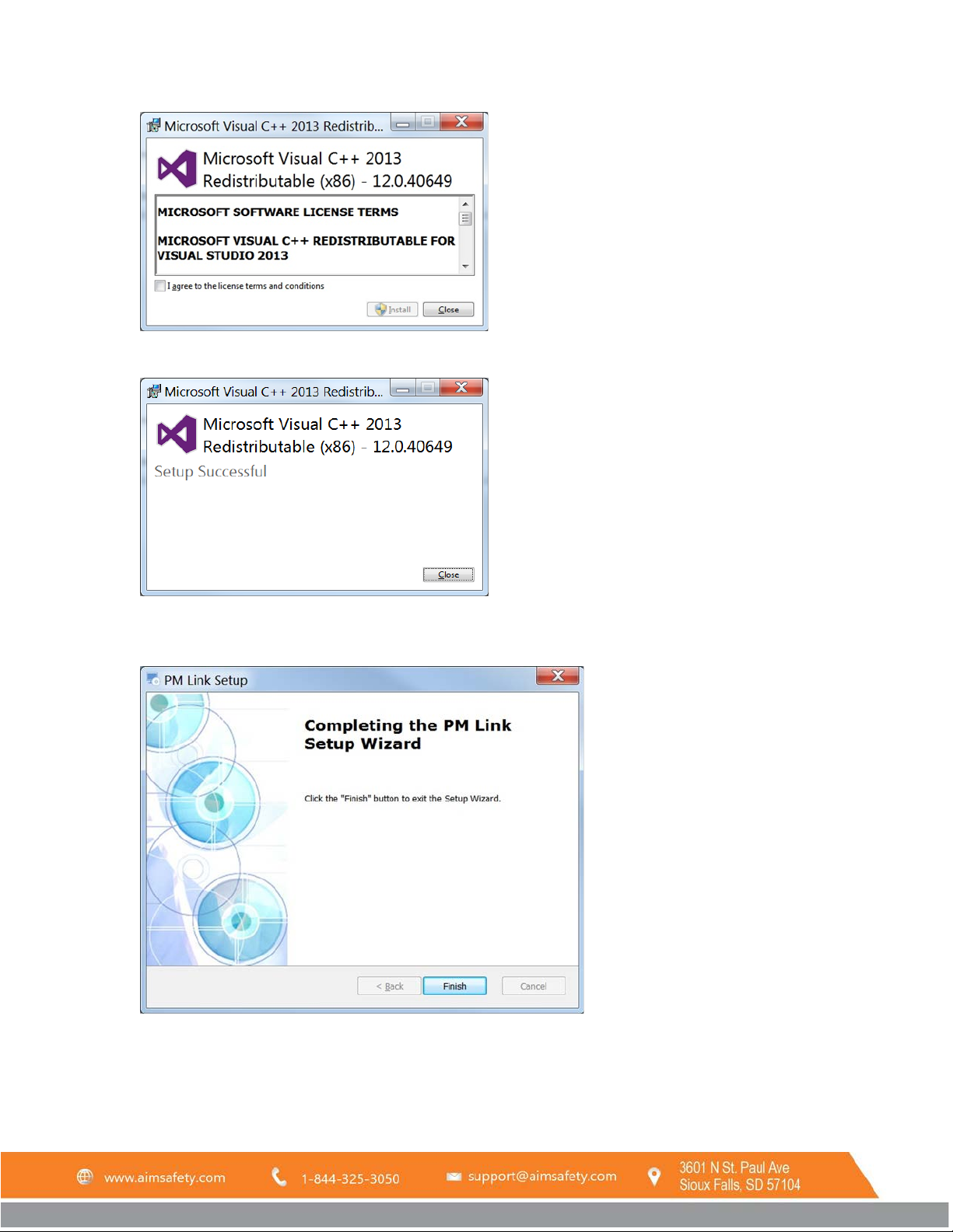
5. At this point, the system may need to install Microsoft Visual C++. These are files that help the PM Link
software run.
NOTE: If you already have these files installed on your system, the installation will skip to Step
Check the box labeled “I agree to the license terms and conditions” and click Install.
REV – 1.0 [34-2900-0510-4] 6 | Page
Page 7
PM Link User Manual
6. You may receive a security warning. Click Yes to continue.
7. When the Microsoft Visual C++ installation is finished, the Setup Successful window displays. Click Close.
8. The rest of the installation process continues. You may receive another security warning. Click Yes to
continue.
9. When the installation is finished, you will see “Click Finish to exit the Setup Wizard.” Click Finish.
10. The software is ready to use.
REV – 1.0 [34-2900-0510-4] 7 | Page
Page 8
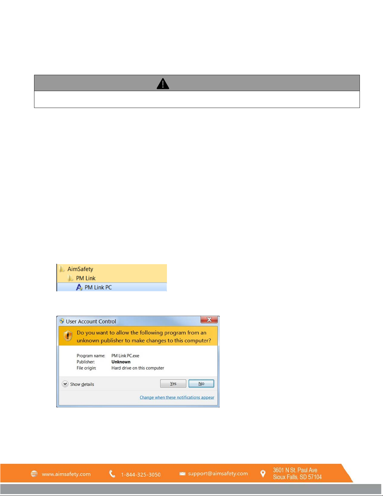
WARNING
Never configure your PM monitor in a hazardous environment. The PM Link does not have an intrinsic safety rating
and can cause an explosion.
PM Link User Manual
2 Operation and User Interface
2.1 Connect the PM Link Hardware to The Computer
The PM Link hardware connects to a USB port on the computer. The PM Link hardware has a Mini-USB port. The PM
Link hardware ships with the required Mini-USB cable. Replacement Mini-USB cables are available via retail.
To connect the PM Link hardware:
1. Connect the large end of the included cable to a USB port on the computer.
2. Connect the small end of the cable to the PM Link hardware.
3. The computer detects your hardware and sets it up for use.
NOTE: If you see a message that your computer can’t find the drivers for your hardware, please follow the
instructions in 1.1 Download and Install Drivers above.
2.2 Launch the Software
To launch the software:
1. Find the PM Link PC icon/launcher in the Start menu under AimSafety folder. Click the Icon.
2. If Windows asks whether you want to allow the software to make changes to the device, click Yes.
3. The software launches. After a moment, the software interface is displayed.
REV – 1.0 [34-2900-0510-4] 8 | Page
Page 9
PM Link User Manual
2.3 Open the PM Link COM Port
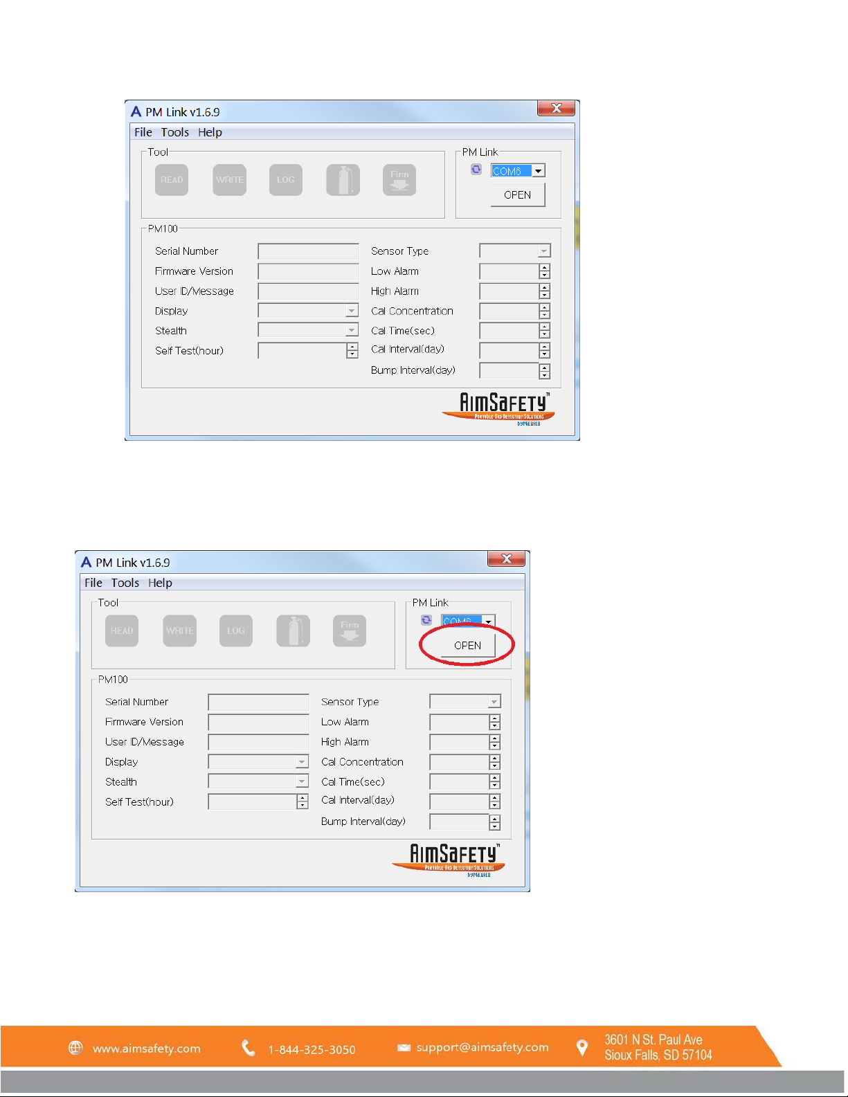
When the PM Link software is first opened, all fields will be grayed out as shown in the above image.
Click the OPEN button to open communication between the PM Link and the computer. Once communication is
established, the PM Link automatically begins scanning for an available PM monitor.
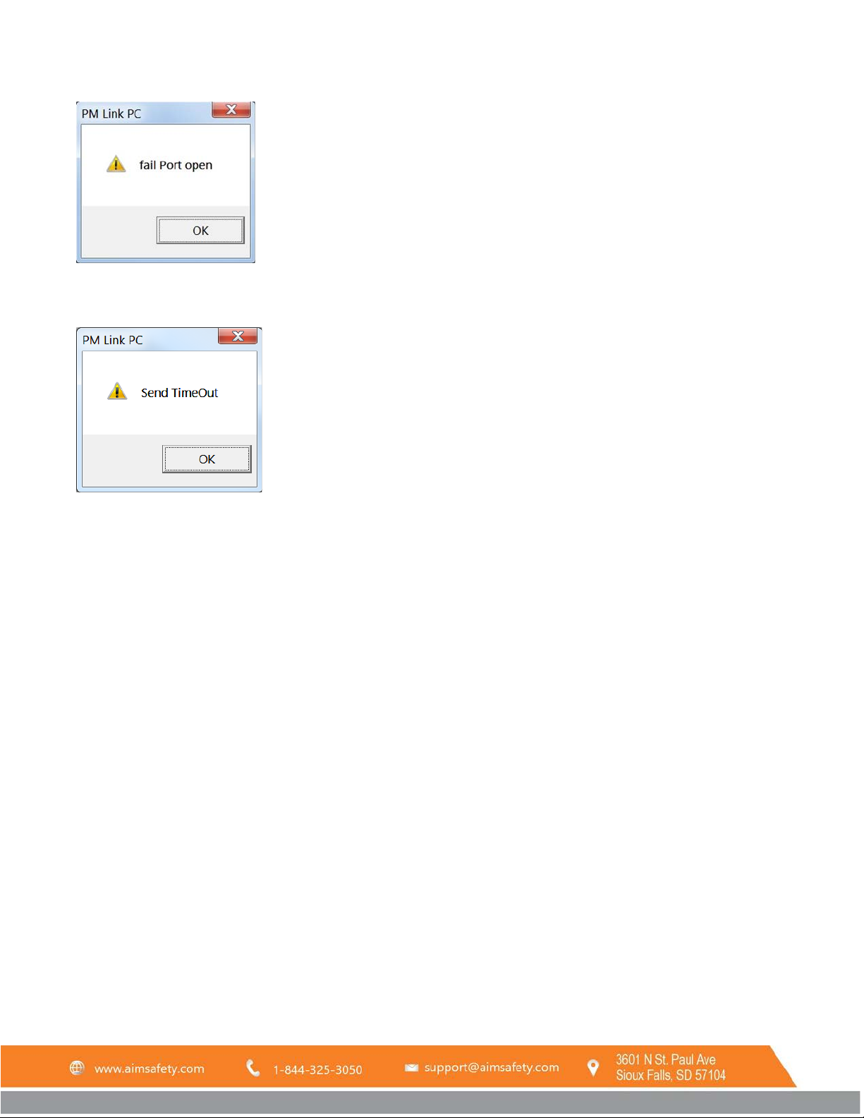
If the PM Link is not found, a "fail Port open" alert pops up. Check to make sure all cables are connected correctly.
REV – 1.0 [34-2900-0510-4] 9 | Page
Page 10
PM Link User Manual
If no PM monitor is found, the "Send TimeOut" alert pops up. Follow the steps in section 2.4 to read the PM
monitor.
2.4 Read a PM monitor
To use the PM Link to read a PM monitor,
1. Ensure the PM monitor is powered on/activated by checking its LCD display.
If the display is blank,
a. Press and hold the orange oval [Function] key on the front of the device. A 3-second count-up timer
displays.
b. Release the [Function] key when the timer reaches 3.
c. The device runs through Firmware and Self-test screens and displays a 10-second countdown timer
before displaying its main screen (either Safe Mode or the Measuring screen). See the device’s Quick
Start Guide or User Manual for more information.
NOTE: The PM monitor will not communicate with the PM Link software until the 10-second countdown
timer in the monitor is complete.
2. When the PM monitor is powered on and 10-second countdown timer is complete, place it so the IR port at
the top of the PM monitor faces the IR port on the PM Link hardware.
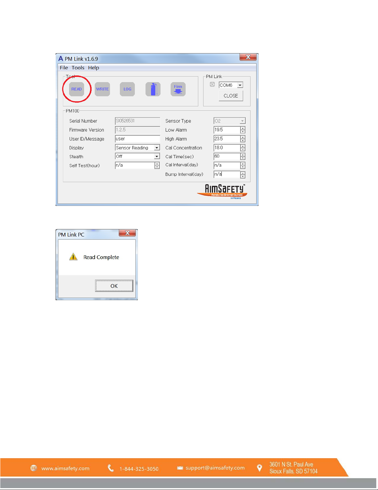
3. If the COM port is not already open, click the OPEN button in the PM Link section of the software screen as
described in section 2.3. If the COM port is already open, click READ in the Tool section of the software
REV – 1.0 [34-2900-0510-4] 10 | Page
Page 11
PM Link User Manual
screen.
4. The PM Link hardware reads the current configuration from the monitor. A Read Complete alert pops up
when this is done. Click OK to close the alert.
5. The PM Link interface updates to reflect the current configuration of the PM monitor. The software will
detect whether the reading was taken from a PM
or a PM
100
monitor and will display the appropriate
400
screen.
REV – 1.0 [34-2900-0510-4] 11 | Page
Page 12
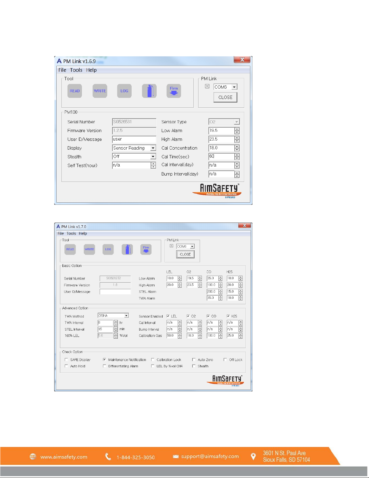
PM Link User Manual
Figure 2-1 PM
Figure 2-2PM400 Configuration screen
Configuration screen
100
3 PM Monitor Configuration
The PM Link software interface consists of a single screen that allows you to customize the functionality of the PM
monitor. When connected, it detects whether using a PM
REV – 1.0 [34-2900-0510-4] 12 | Page
or a PM
100
and displays the appropriate screen.
400
Page 13
PM Link User Manual
3.1 Load A Configuration
A configuration can be loaded by either reading the configuration of a PM monitor or loading a saved configuration
file.
3.1.1 Read the Current Configuration from a PM monitor
With the PM monitor in front of the PM Link, click the Read button in the Tool menu to read a PM monitor’s
configuration (see section 2.4) at any time. The software will display the PM monitor's current configuration.
3.1.2 Load a Previously Saved Configuration File
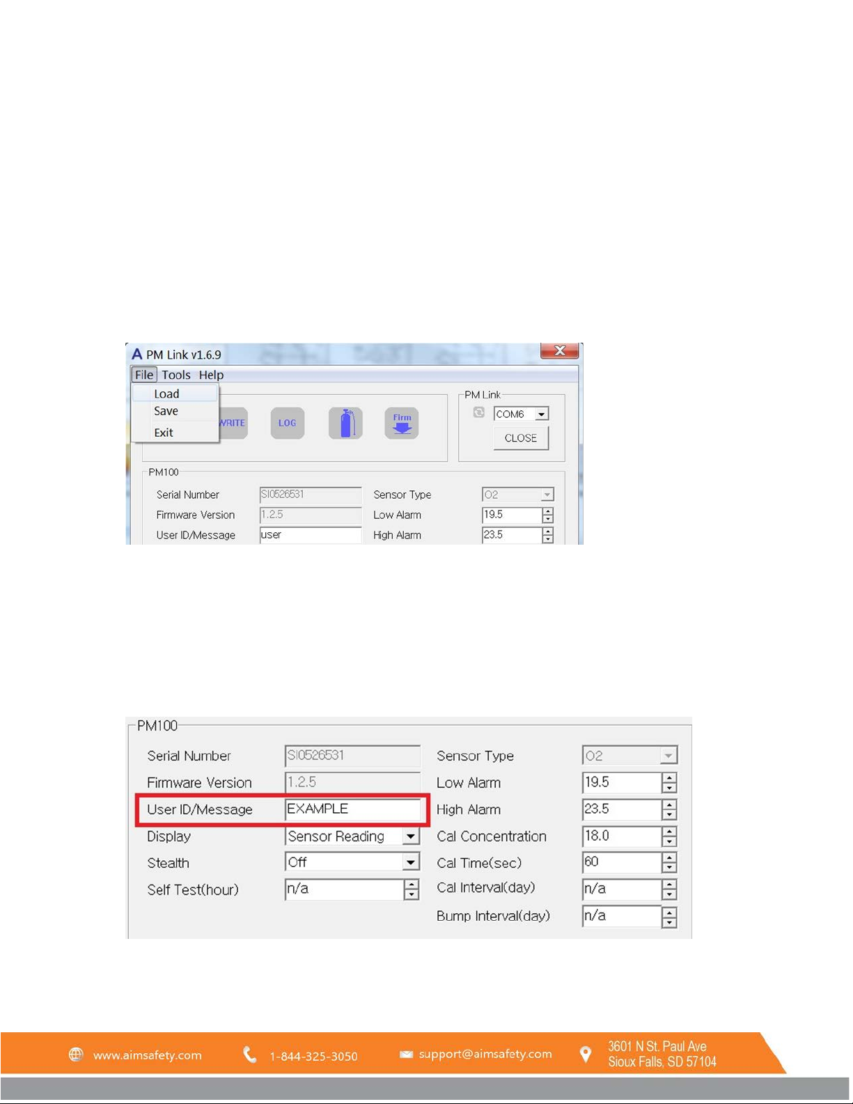
To load a previously saved configuration file (See section 3.5 for directions on how to save a configuration file), click
File from the PM Link menu bar. Click Load from the drop-down menu. The “open file” window will open. Navigate
to the desired configuration file and click Open.
3.2 PM
Once a configuration from a PM
to reflect the current configuration.
Fields which are not grayed out can be changed.
Configuration Options
100
100
monitor is loaded into the software, the PM Link software display updates itself
3.2.1 User Id/Message:
To configure User Id/Message:
REV – 1.0 [34-2900-0510-4] 13 | Page
Page 14
PM Link User Manual
1. Highlight the contents of the field by double-clicking in it. Press backspace to remove any leading spaces that
may be present.
2. Enter up to twelve numbers or letters in the field.
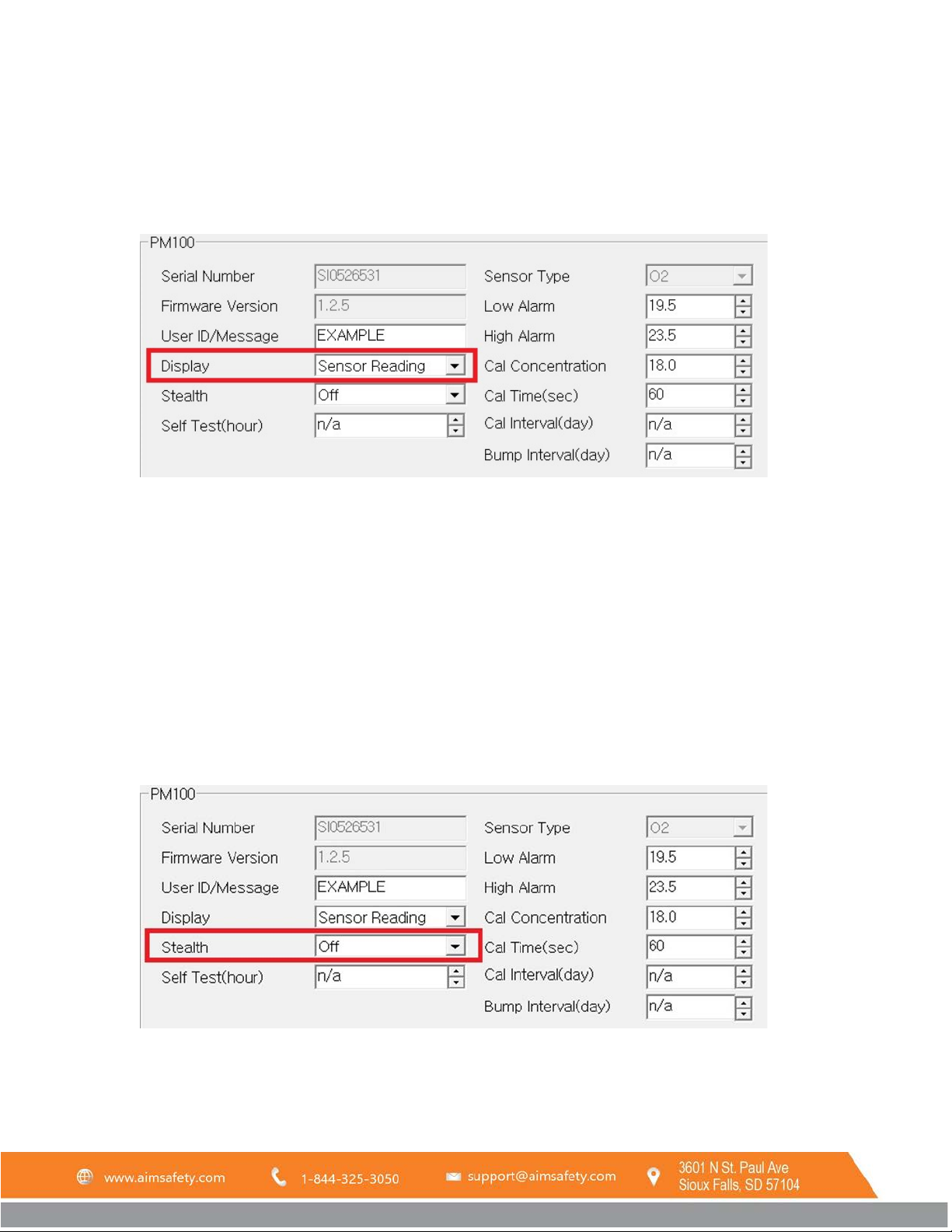
3.2.2 Display
Changes the appearance of the PM
monitor’s Main Screen to display real time gas readings or remaining life of
100
the unit.
Display options:
• Sensor Reading – The PM
• Sensor/Life – The PM
monitor displays real-time gas readings on the main screen.
100
monitor displays the number of months remaining in the life of the unit on the Main
100
Screen.
NOTE: Real time sensor readings are always displayed when an alarm condition is met.
To configure the display reading, click the arrow to open the pulldown menu and select the option you prefer.
3.2.3 Stealth
Enables or disables stealth mode on the PM
LEDs. If set to stealth mode, the PM
monitor display alarm flags are the only indication of an alarm condition.
100
monitor. Stealth mode disables all audible, vibrating alarms and alarm
100
REV – 1.0 [34-2900-0510-4] 14 | Page
Page 15
WARNING
When stealth mode is enabled all alarm, functions are disabled. Stealth mode should be used with caution.
PM Link User Manual
Stealth Options:
• Off – Disables stealth mode
• On – Enables stealth mode
To configure stealth settings, open the pulldown menu and select the preferred option.
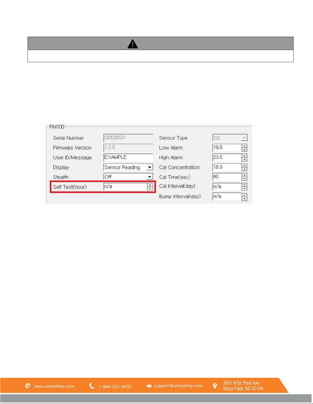
3.2.4 Self-Test
Sets the interval after which the device will prompt the user to perform the self-test.
Self-Test Options:
• n/a – The unit will not automatically self-test.
• 8-20 – The number of hours between tests.
To configure self-test readings, double-click in the field to highlight the number and enter a new value or use the up
and down arrows to increase or decrease this value.
Note: See PM100 User’s Manual for more information on the self-test option.
REV – 1.0 [34-2900-0510-4] 15 | Page
Page 16
Alarm values are set based on the alarm standard that are required by international standards. Therefore, alarm
the instrument is used.
PM Link User Manual
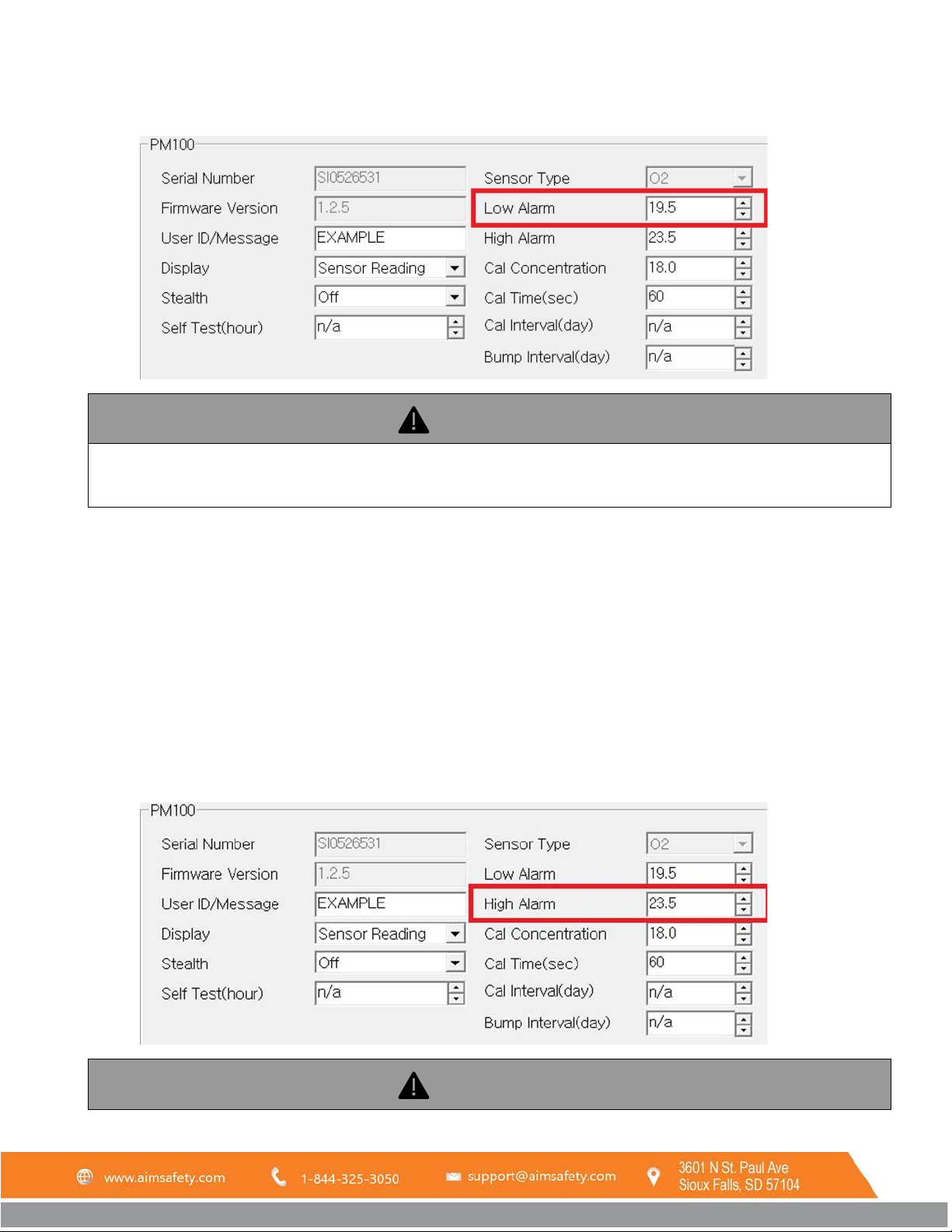
3.2.5 Low Alarm
values should be changed only under the responsibility and approval of the administration of the work site where
Dictates the low alarm setpoint. When gas concentration becomes less than this setpoint, the low alarm activates.
Low Alarm Options:
• n/a – The low alarm is disabled.
WARNING: Disabling the Low Alarm is not recommended. Alarm values should be changed only under the
responsibility and approval of the administration of the work site where the instrument is used.
• Number – The available range and resolution will depend on the type of gas sensor.
To configure the low alarm, double-click in the field to highlight the number and enter a new value or use the up and
down arrows to increase or decrease this value.
3.2.6 High Alarm
REV – 1.0 [34-2900-0510-4] 16 | Page
Page 17
Alarm values are set based on the alarm standard that are required by international standards. Therefore, alarm
the instrument is used.
PM Link User Manual
values should be changed only under the responsibility and approval of the administration of the work site where
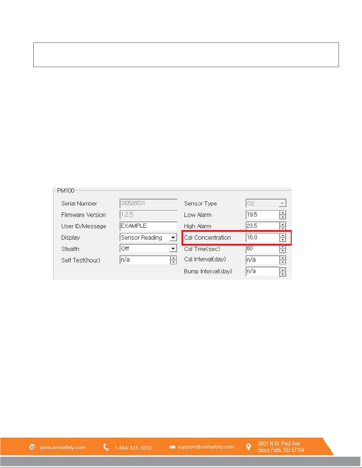
Dictates the high alarm setpoint. When gas concentration becomes greater than this setpoint, the high alarm
activates.
High Alarm Options:
• n/a – The high alarm is disabled.
WARNING: Disabling the High Alarm is not recommended. Alarm values should be changed only under the
responsibility and approval of the administration of the work site where the instrument is used.
• Number range – The available range and resolution will depend on the type of gas sensor.
To configure the high alarm, double-click in the field to highlight the number and enter a new value or use the up
and down arrows to increase or decrease this value.
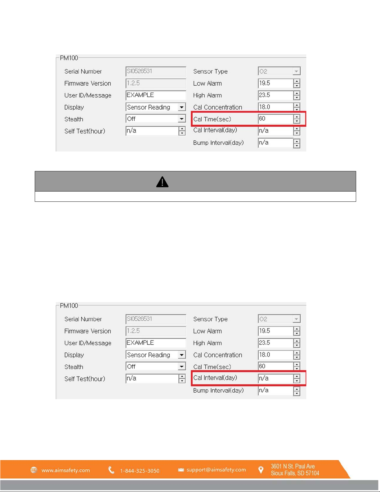
3.2.7 Cal (Calibration) Concentration
Changes the required calibration gas concentration for the sensor.
Cal Concentration Options:
• Number range – The available range and resolution will depend on the type of gas sensor.
Note: The calibration gas value is displayed in the measurement units of the specific gas sensor type. (i.e.
ppm for CO/H
2
S and % Vol for O2)
To configure the Cal concentration, double-click in the field to highlight the number and enter a new value or use
the up and down arrows to increase or decrease this value.
REV – 1.0 [34-2900-0510-4] 17 | Page
Page 18
Do not adjust the calibration time unless instructed to do so by the factory.
PM Link User Manual
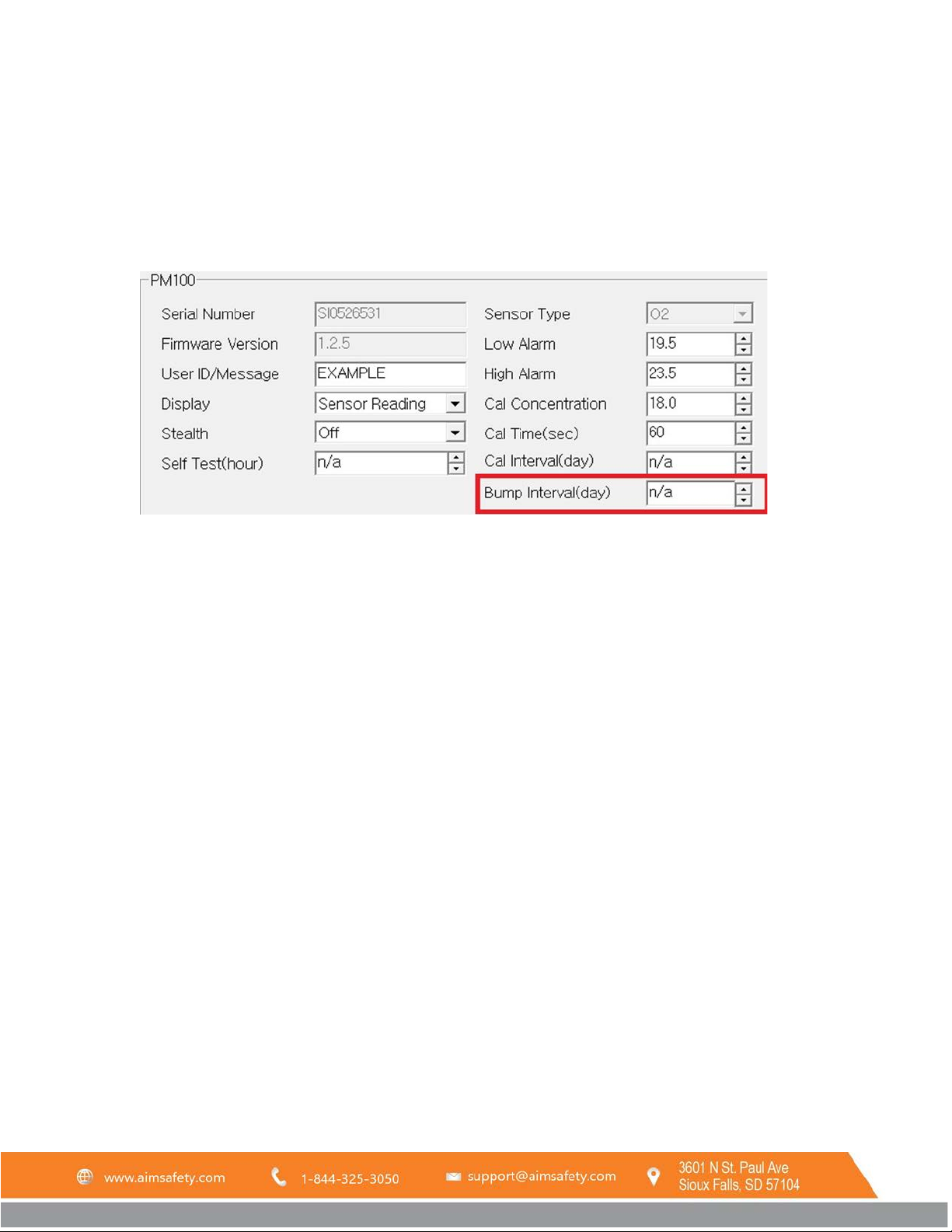
3.2.8 Cal Time (sec)
Dictates the duration in seconds that the device will take to calibrate.
Cal Time Options:
• n/a
• 1-300 – Number of seconds required for calibration.
To configure Cal time, double-click in the field to highlight the number and enter a new value or use the up and
down arrows to increase or decrease this value.
3.2.9 Cal Interval (day)
Dictates the number of days after which the PM
monitor will display a calibration alert and require calibration.
100
Cal Interval Options:
• n/a – Calibration alerts will be disabled.
REV – 1.0 [34-2900-0510-4] 18 | Page
Page 19
PM Link User Manual
• 1-365 – Number of days between calibration alerts.
To configure Cal Interval, double-click in the field to highlight the number and enter a new value or use the up and
down arrows to increase or decrease this value.
NOTE: For more information on Cal due, see the PM
Manual.
100
3.2.10 Bump Interval (day)
Dictates the number of days after which the PM
Bump Interval Options:
• n/a – Bump test alerts will be disabled.
• 1-365 – Number of days between bump test alerts.
To configure bump interval, double-click in the field to highlight the number and enter a new value or use the up
and down arrows to increase or decrease this value.
monitor will display a Bump Test alert and require a bump test.
100
NOTE: For more information on Bump Test due, see the PM
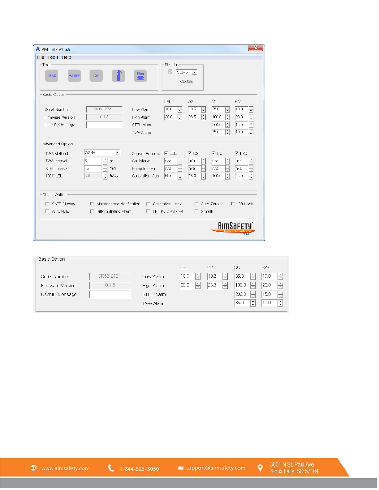
3.3 PM
If a configuration from a PM
the current configuration. The PM
Configuration Options
400
monitor is loaded into the software, the PM Link software display updates to reflect
400
interface is shown below.
400
Manual.
100
REV – 1.0 [34-2900-0510-4] 19 | Page
Page 20
PM Link User Manual
3.3.1 Basic Options
3.3.1.1 User ID/Message
To configure User Id/Message:
1. Highlight the contents of the field by double-clicking in it. Press backspace to remove any leading spaces that
may be present.
2. Enter up to twelve numbers or letters in the field.
3.3.1.2 Low Alarm
Dictates the Low Alarm setpoint. When gas concentration becomes less than this setpoint, the Low Alarm activates.
Low Alarm Options:
REV – 1.0 [34-2900-0510-4] 20 | Page
Page 21

PM Link User Manual
• n/a – The Low Alarm is disabled.
WARNING: Disabling the Low Alarm is not recommended. Alarm values should be changed only under the
responsibility and approval of the administration of the work site where the instrument is used.
• Number – LEL: 0.1 – 100.0% , O
: 0.1 – 30.0% vol, CO: 0.1 - 500.0 ppm, H2S: 0.1 – 100.0 ppm
2
To configure the Low Alarm, double-click in the field to highlight the number and enter a new value or use the up
and down arrows to increase or decrease this value.
3.3.1.3 High Alarm
Dictates the High Alarm setpoint. When gas concentration becomes greater than this setpoint, the High Alarm
activates.
High Alarm Options:
• n/a – The High Alarm is disabled.
WARNING: Disabling the High Alarm is not recommended. Alarm values should be changed only under the
responsibility and approval of the administration of the work site where the instrument is used.
• Number range – LEL: 0.1 – 100.0% , O
To configure the High Alarm, double-click in the field to highlight the number and enter a new value or use the up
and down arrows to increase or decrease this value.
: 0.1 – 30.0% vol, CO: 0.1 - 500.0 ppm, H2S: 0.1 – 100.0 ppm
2
3.3.1.4 STEL Alarm
The Short Term Exposure Limit Alarm is configurable for CO and H
S. When the average gas concentration over the
2
time period (determined by the STEL Interval, see 3.3.2.3) is greater than this setpoint, the STEL Alarm activates.
STEL Alarm Options:
• n/a – The STEL Alarm is disabled.
• Number range – CO: 0.1 - 500.0 ppm, H
S: 0.1 – 100.0 ppm
2
To configure the STEL Alarm, double-click in the field to highlight the number and enter a new value or use the up
and down arrows to increase or decrease this value.
3.3.1.5 TWA Alarm
Time Weighted Average Alarm is configurable for CO and H
period (determined by the TWA Method and TWA Interval, see 3.3.2.1 and 3.3.2.2) is greater than this setpoint, the
TWA Alarm activates.
TWA Alarm Options:
• n/a – The TWA Alarm is disabled.
• Number range – CO: 0.1 - 500.0 ppm, H
S: 0.1 – 100.0 ppm
2
S. When the average gas concentration over the time
2
REV – 1.0 [34-2900-0510-4] 21 | Page
Page 22
PM Link User Manual
To configure the TWA Alarm, double-click in the field to highlight the number and enter a new value or use the up
and down arrows to increase or decrease this value.
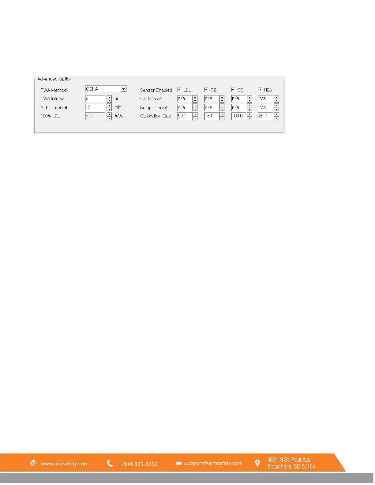
3.3.2 Advanced Options
3.3.2.1 TWA Method
The Time Weighted Average method determines the method used to calculate the value for the TWA Alarm. It is
selectable between OSHA and ACGIH methods.
To configure the TWA Method, click the arrow to open the pulldown menu and select the option you prefer.
3.3.2.2 TWA Interval
Time Weighted Average Interval determines the time period over which the Time Weighted Average will be
calculated.
The selectable range is 4-16 hours if OSHA is selected as the TWA Method. If the TWA Method is ACGIH, the TWA
Interval will not be changeable and will be set at 16 hours.
To configure TWA Interval, double-click in the field to highlight the number and enter a new value or use the up and
down arrows to increase or decrease this value.
3.3.2.3 STEL Interval
The Short Term Exposure Limit Interval determines the period over which the Short Term Exposure Limit is
calculated.
The STEL Interval can be set to “n/a” or 5-15 minutes. If it is set to “n/a”, the STEL Alarm will be disabled.
To configure STEL Interval, double-click in the field to highlight the number and enter a new value or use the up and
down arrows to increase or decrease this value.
3.3.2.4 100% LEL
This feature allows for LEL gas readings based on a specific gas type. The default setting is 5% Vol for Methane
indicating that 5% Vol of methane is equal to 100% of the Lower Explosive Limit of the gas.
It can be changed by selecting the LEL % Vol check box on the bottom of the screen (see 3.3.3.6).
3.3.2.5 Sensor Enabled
Each gas sensor on the PM
REV – 1.0 [34-2900-0510-4] 22 | Page
monitor can be enabled or disabled. Check/uncheck the corresponding box to
400
Page 23
PM Link User Manual
enable/disable the gas sensor. If a gas type is disabled, the corresponding options for that gas will turn gray and no
longer be changeable.
3.3.2.6 Cal Interval
Determines the number of days after which the PM
A Cal Interval can be set for each gas type.
Cal Interval Options:
• n/a – Calibration alerts will be disabled.
• 1-365 – Number of days between calibration alerts.
To configure Cal Interval, double-click in the field to highlight the number and enter a new value or use the up and
down arrows to increase or decrease this value.
monitor will display a calibration alert and require calibration.
400
NOTE: For more information on Cal due, see the PM
Manual.
400
3.3.2.7 Bump Interval
Determines the number of days after which the PM
monitor will display a Bump Test alert and require a bump
400
test. A Bump Interval can be set for each gas type.
Bump Interval Options:
• n/a – Bump test alerts will be disabled.
• 1-365 – Number of days between Bump test alerts.
To configure Bump Interval, double-click in the field to highlight the number and enter a new value or use the up
and down arrows to increase or decrease this value.
NOTE: For more information on Bump Test due, see the PM
Manual.
400
3.3.2.8 Calibration Gas
Sets the concentration of the gas used for calibration. If a calibration gas is used that does not match the Calibration
Gas values, the monitor will not be calibrated correctly.
• n/a – The calibration gas does not include this gas type.
• Number range – LEL: 0.1 – 100.0%, O
To configure the Calibration Gas, double-click in the field to highlight the number and enter a new value or use the
up and down arrows to increase or decrease this value.
: 0.1 – 30.0% vol, CO: 0.1 – 600.0 ppm, H2S: 0.1 – 100.0 ppm
2
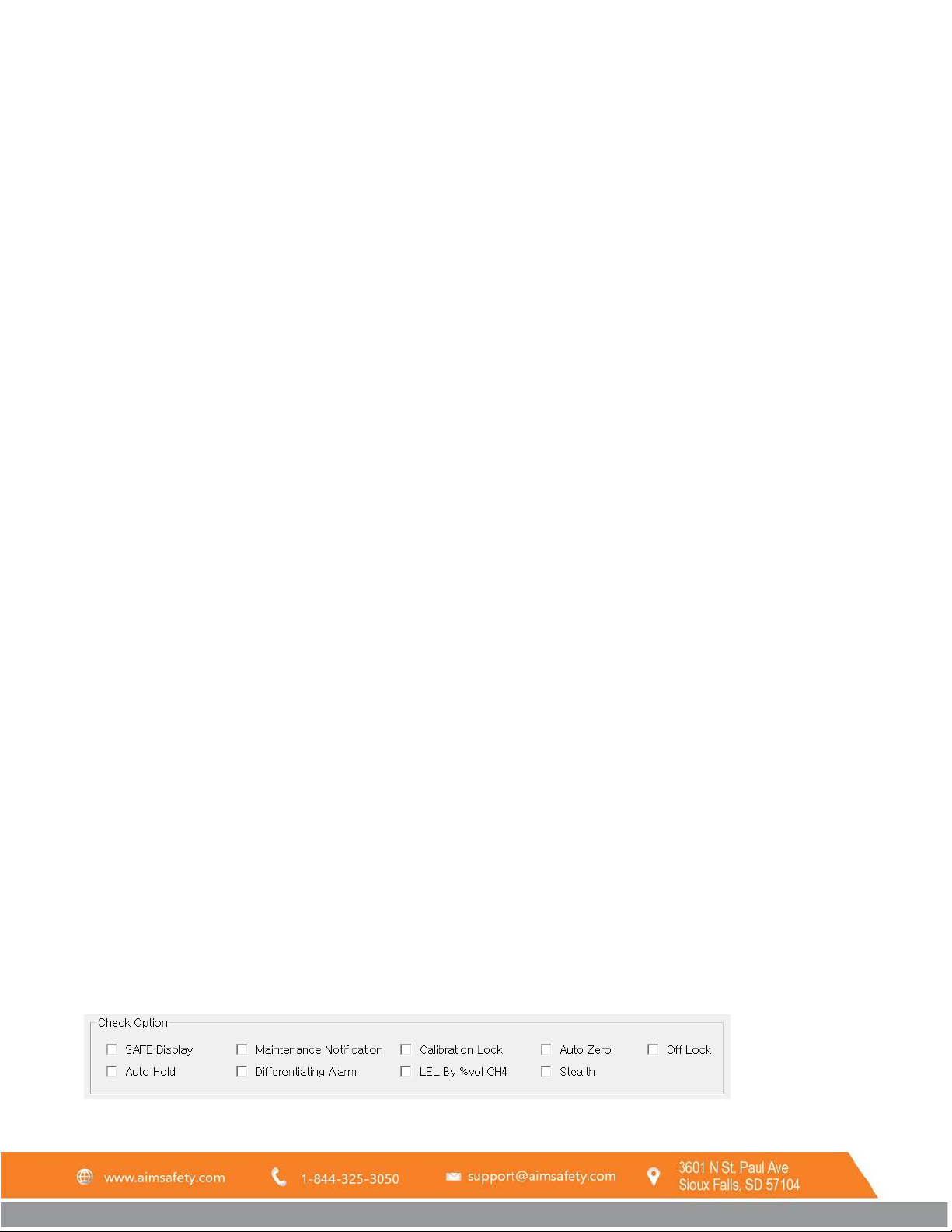
3.3.3 Check Options
REV – 1.0 [34-2900-0510-4] 23 | Page
Page 24

PM Link User Manual
3.3.3.1 SAFE Display
When the box is checked, the monitor display will read “SAFE ZONE” when no alarm conditions are met.
3.3.3.2 Auto Hold
Check the box to enable “latching alarms” where once an alarm condition is met, the unit will stay in alarm until the
alarm has been acknowledged by pressing the function key.
3.3.3.3 Maintenance Notification
Check the box to enable the Calibration and Bump Test Due notifications (see 3.3.2.6 and 3.3.2.7).
3.3.3.4 Differentiating Alarm
When the box is checked, the unit will beep once during alarm for a single gas, twice for two gases, three times for
three gases.
3.3.3.5 Calibration Lock
When the box is checked, manual field calibration will be disabled. The monitor can only be calibrated using the PM
Link and software or the Bump Test and Calibration Station.
3.3.3.6 LEL by %vol CH4
Check the box to enable a custom setting for the 100% LEL setting (see 3.3.2.4). If this box is left unchecked, the
100% LEL setting will be grayed out and the default value of 5% will be used.
3.3.3.7 Auto Zero
The Auto Zero option sets the sensors to fresh air during the power-on sequence.
NOTE: The detector must only be turned on in a known safe environment with this feature enabled.
3.3.3.8 Stealth
Stealth mode disables all audible, vibrating, and LED alarms. If set to stealth mode, the PM
flags are the only indication of an alarm condition.
monitor display alarm
400
3.3.3.9 Off Lock
Check Off Lock to prevent the monitor from being turned off. If a user tries to power off the monitor with Off Lock
engaged, the screen will flash “OFF LOCK” and continue operating normally.
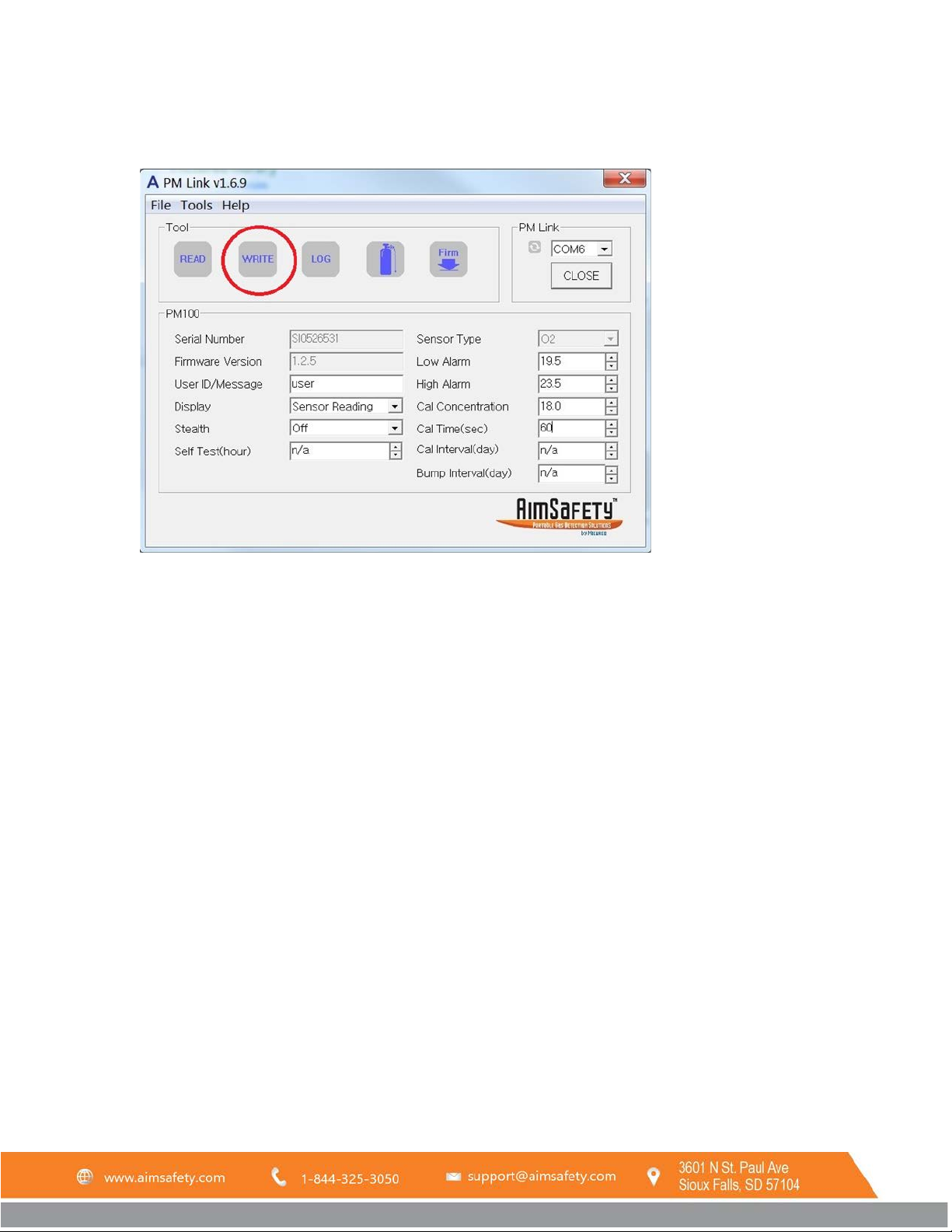
3.4 Write the New Configuration to the PM Monitor
The PM Link software does not automatically send new settings to the PM monitor.
REV – 1.0 [34-2900-0510-4] 24 | Page
Page 25
PM Link User Manual
With the PM monitor in front of the PM Link, click the WRITE button in the Tool menu at any time to transfer the
new configuration to the PM monitor.
3.5 Save a Configuration to File
To quickly configure multiple PM monitors, it can be useful to save a desired configuration.
To save a configuration to file:
1. click File on the menu bar and select Save from the dropdown menu.
2. A Save As window will open. Select a location you will remember and name the file. By default, the file will
be saved as a .cfg file.
3. Click Save.
4 PM100/400 Calibration
Calibration is the process of adjusting the sensor’s response by using a specific concentration of calibration gas.
Over time, sensors will lose accuracy for a variety of reasons. Therefore, it is important to periodically perform a full
calibration to ensure the sensor’s response to the target gas is accurate.
A full calibration consists of two parts:
1. Zero Calibration – Clean air is used to calibrate the sensor (also referred to as fresh air calibration).
2. Span Calibration – A known concentration of gas is used to calibrate the sensor.
NOTE: The following calibration instructions assume that the PM Link hardware is “connected to” (communicating
over IR with) a PM monitor. See section Error! Reference source not found. Error! Reference source not found..
REV – 1.0 [34-2900-0510-4] 25 | Page
Page 26
PM Link User Manual
4.1 Zero Calibration
For the PM
the PM
NOTE: Zero calibration must be performed in a clean environment that is free from other gases (calibration is
assumed to be performed in an environment with an oxygen concentration of 20.9% Vol.). Never perform a zero
calibration in a confined space or in a non-clean air environment.
To Perform a Zero Calibration:
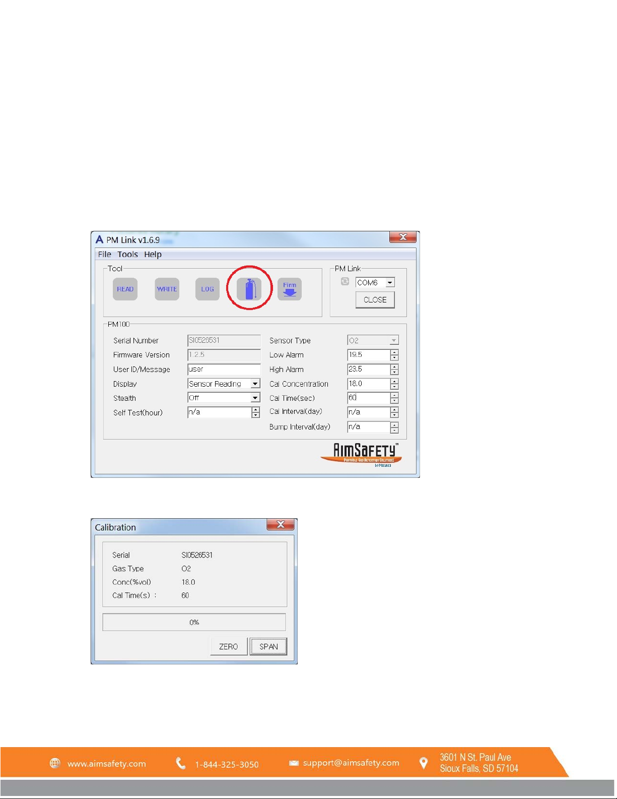
1. Click the Calibration icon in the Tool section of the interface or select Calibration from the Tools dropdown
, zero calibration will set the zero offset of the toxic sensor or set the oxygen sensor to 20.9% Vol. For
100
, zero calibration will set the zero offset of the toxic and LEL sensor and set the oxygen sensor to 20.9% Vol.
400
on the menu bar.
2. The Calibration interface appears. Click the ZERO button.
3. A dialog box pops up, asking, “Do you want to start Zero Calibration?” Click Yes to begin Zero Calibration or
click No to cancel.
REV – 1.0 [34-2900-0510-4] 26 | Page
Page 27
PM Link User Manual
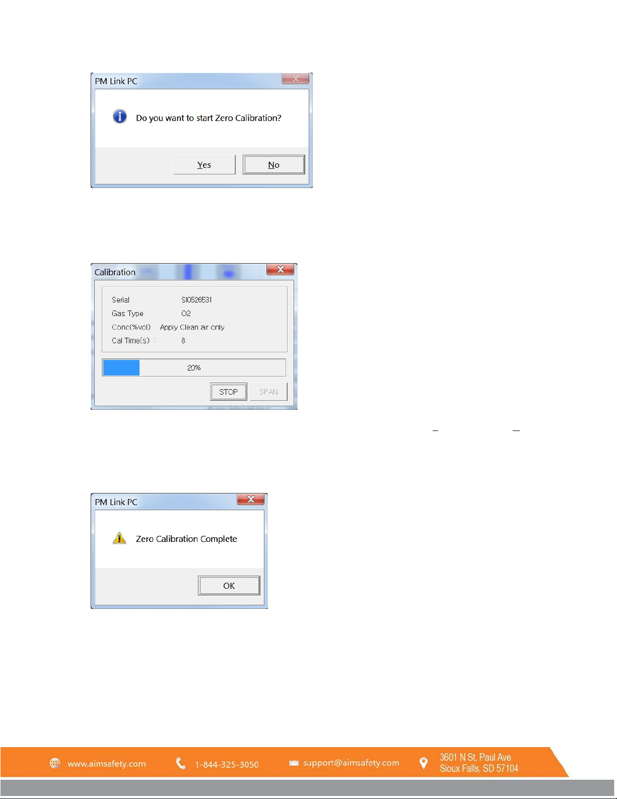
4. When zero calibration starts, the blue light on top of the PM Link device will begin to flash rapidly. The
Calibration window will show a ten-second countdown timer. As the timer counts down from ten, the
progress meter rises in increments of 10%. When the timer reaches zero and the meter reaches 100%, Zero
Calibration is finished.
NOTE: To cancel the calibration, click on STOP. A new window will pop up. Click Yes to confirm or No to return
to the calibration in progress. Clicking the “X” to close the window does not stop the calibration.
5. Once the countdown is complete, a successful zero calibration will be indicated by a message box. Click OK
to return to the Calibration window.
If the calibration fails repeatedly, please contact the sales representative or technical support.
4.2 Span Calibration
Span calibration adjusts the sensors response to gas to account for sensor drift. It is recommended to perform a
Zero Calibration prior to a Span Calibration.
To perform a Span Calibration:
REV – 1.0 [34-2900-0510-4] 27 | Page
Page 28
PM Link User Manual
1. Attach the calibration cap to the top of the PM monitor’s sensor inlet.
2. Connect the hose from the gas regulator of the calibration gas bottle to the calibration cap.
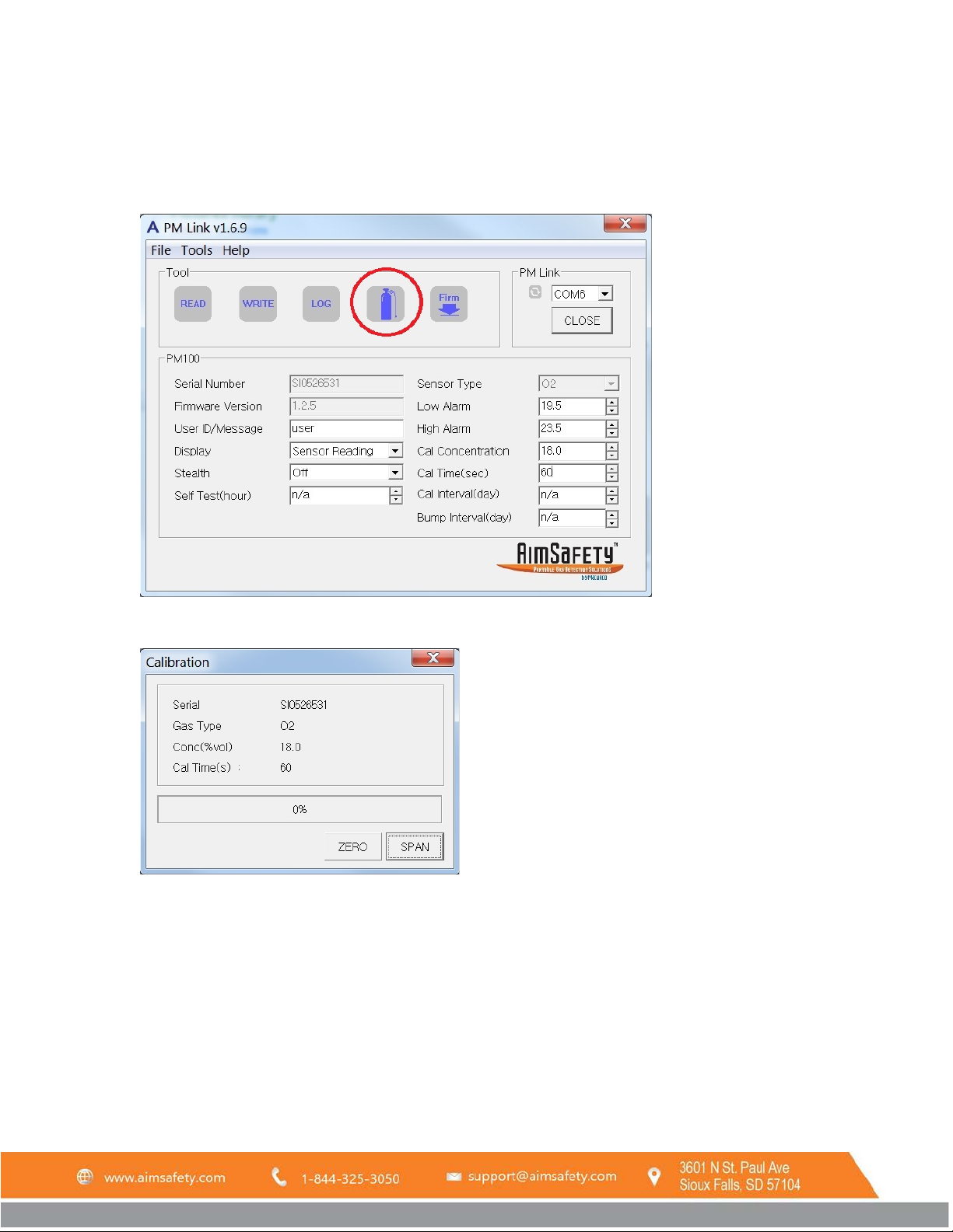
3. Click the Calibration icon in the Tool section of the interface or select Calibration from the Tools dropdown
on the menu bar.
4. The Calibration window appears. Click the SPAN button.
5. A dialog box pops up, asking, “Do you want to start Span Calibration?” Click Yes to begin Span Calibration or
click No to cancel and return to the calibration window.
REV – 1.0 [34-2900-0510-4] 28 | Page
Page 29
PM Link User Manual
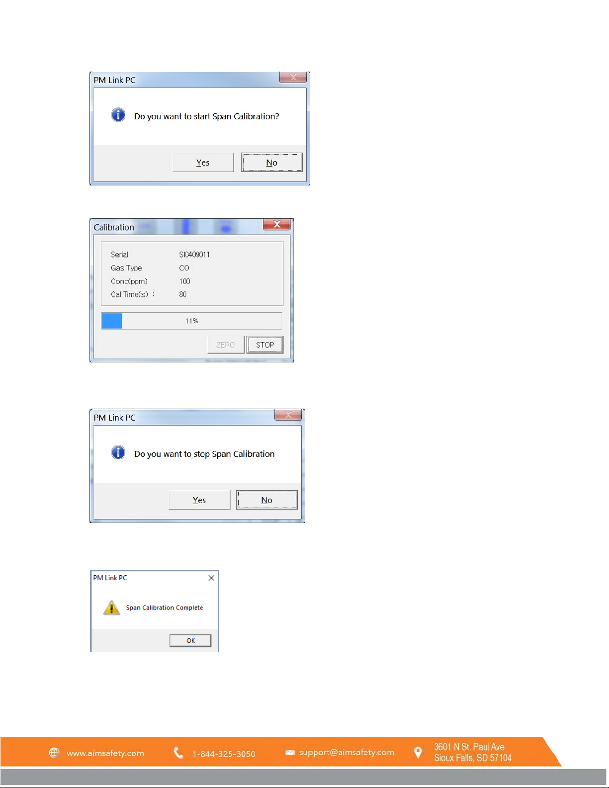
6. When the calibration starts, a countdown timer displays the remaining time. Turn on the calibration gas
NOTE: To cancel the calibration, click on STOP. A new window will pop up. Click Yes to confirm or No to return to
the calibration in progress. Clicking the X does not stop the calibration.
7. Once the countdown reaches zero, the calibration is complete. A completed span calibration will be
indicated by a message box. Click OK to continue.
If the calibration fails repeatedly, please contact the sales representative or AimSafety technical support.
8. Turn off the calibration gas and remove the calibration cap.
REV – 1.0 [34-2900-0510-4] 29 | Page
Page 30
PM Link User Manual
5 Firmware Upgrade
Firmware is software that’s embedded into your hardware. Firmware upgrades are intended to enable or enhance
hardware features and improve the user interface. While some firmware updates are more critical than others, it’s
good practice to keep your firmware updated to the latest version to get the most benefit from your PM monitor.
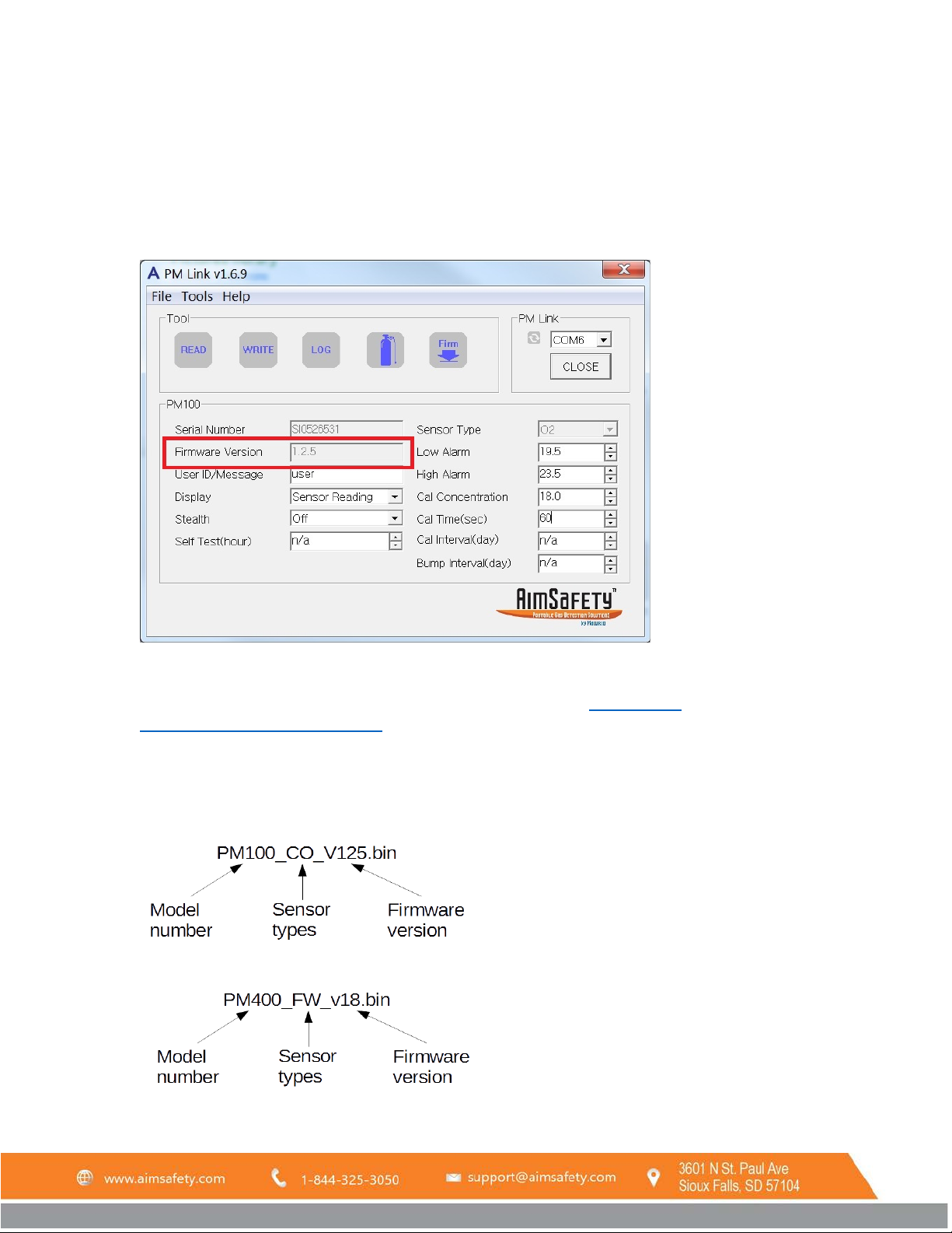
Your PM monitor’s current firmware version is displayed in the PM Link interface.
To upgrade the firmware:
1. Download the latest firmware file for your PM monitor from the product page
https://macurco.com/downloads/. Save it someplace easy to remember.
NOTE: Make sure to download the firmware for the correct PM monitor model. The wrong firmware won’t
work. Firmware files follow a specific naming convention as follows:
PM
Example:
100
PM400 Example:
or at
REV – 1.0 [34-2900-0510-4] 30 | Page
Page 31
PM Link User Manual
2. Connect the PM monitor to the PM Link as described in section Error! Reference source not found..
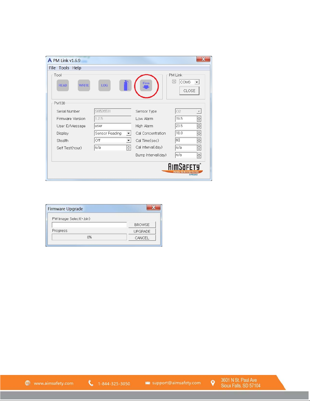
3. Click Firm in the Tool section of the interface or select FW Upgrade from the Tools dropdown menu.
4. The Firmware Upgrade interface appears. Click BROWSE and find the file you saved to your computer in step
one.
5. Double-click the file. The filename displays in the FW Image Select field.
6. Confirm the PM monitor is positioned correctly to communicate with the PM Link hardware.
7. Click UPGRADE to begin the firmware upgrade. The progress meter advances to the right and the percent
complete counts upward to 100%.
6 Logging
The PM monitor automatically saves a record of events in the memory. Event logging occurs when:
• an alarm condition is met
• a calibration is performed
• a bump test is performed
• the monitor is turned on or off (PM
400
only)
The stored log events can be viewed using the PM Link or the Bump Test – Calibration Station. For more
information about what is included in the log file, refer to the PM monitor User’s Manual.
REV – 1.0 [34-2900-0510-4] 31 | Page
Page 32
PM Link User Manual
6.1 PM
100
Logs
6.1.1 View Log Data
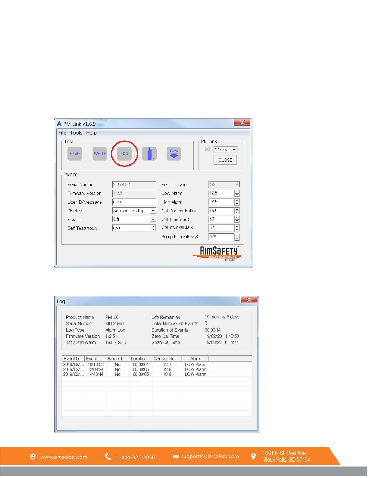
This operation will download and display a list of log events from the PM
log file to the computer.
To view stored log data with the PM Link:
Confirm the PM
1.
2. Click LOG
in the Tool section of the interface or select Log Read from the Tools dropdown menu.
monitor is positioned correctly to communicate with the PM Link hardware.
100
monitor and automatically save the
100
3. The PM Link will read the data from the PM
displayed on the screen and the log files are saved to C:\Program Files (x86)\AimSafety\PM Link\LOG.
monitor and the Log window will open. The log events are
100
REV – 1.0 [34-2900-0510-4] 32 | Page
Page 33
PM Link User Manual
6.1.2 Erase Log Data
This operation will erase the stored log data on the PM
previously saved to the computer.
To erase the stored log data:
monitor. It will not erase any log files which were
100
1. Confirm the PM
monitor is positioned correctly to communicate with the PM Link hardware.
100
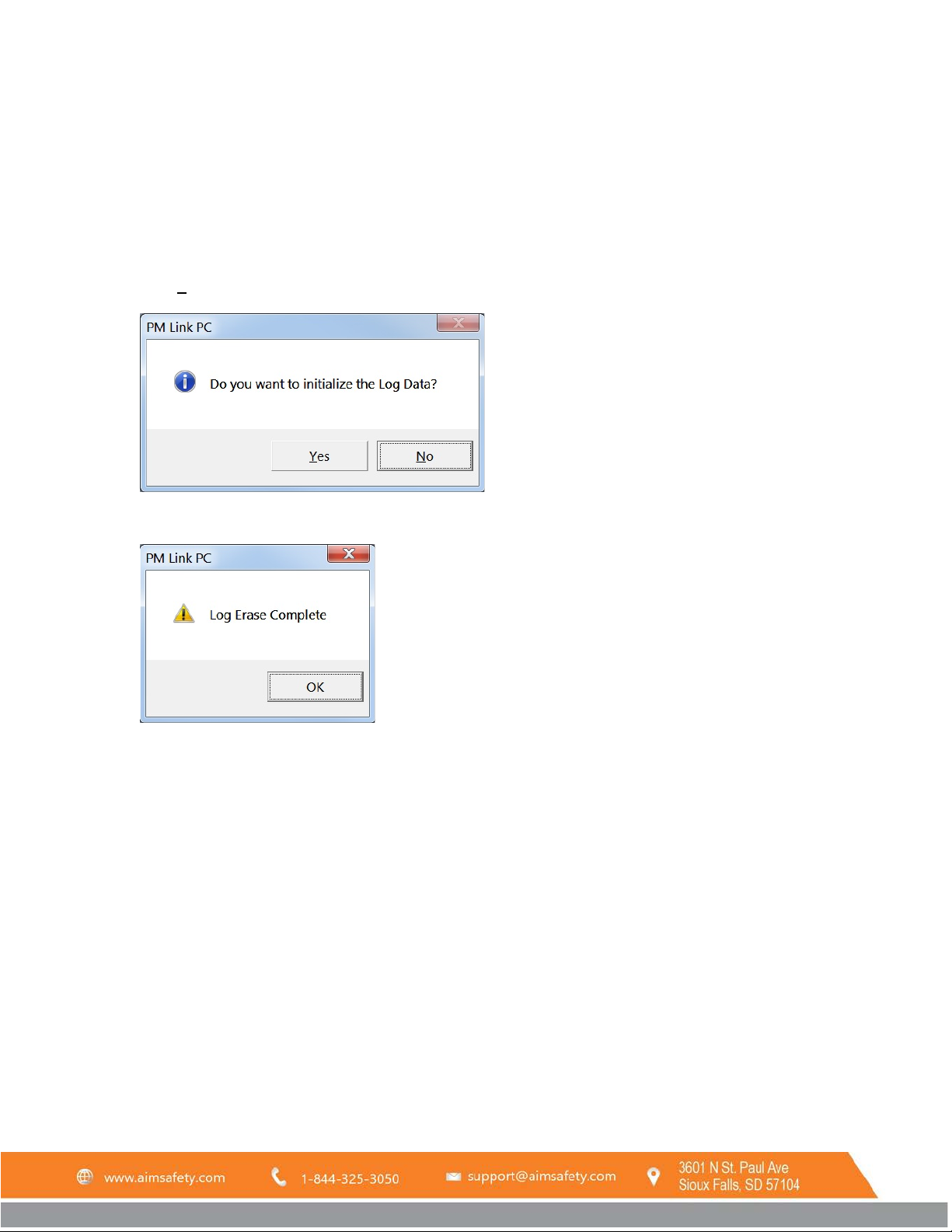
2. Select Log Erase from the Tools dropdown menu.
3. Click Yes to erase the Log Data.
4. The Log Data is erased. Click OK to return to the PM Link interface.
6.2 PM
400
Logs
6.2.1 Download Log File
The PM
log data can be downloaded using the PM Link.
400
To download stored log data using the PM Link:
1.
Confirm the PM
monitor is positioned correctly to communicate with the PM Link hardware.
400
REV – 1.0 [34-2900-0510-4] 33 | Page
Page 34
PM Link User Manual
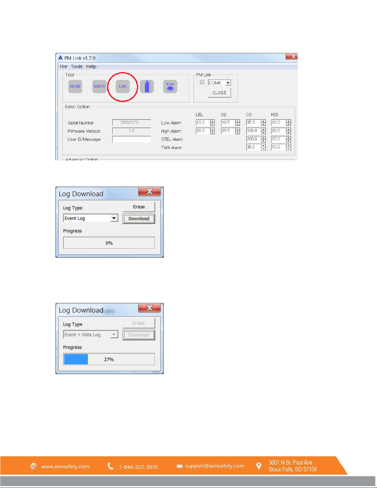
2. Click LOG in the Tool section of the interface or select Log Read from the Tools dropdown menu.
3. The Log Download window will popup. Choose either “Event Log” or “Event + Data Log” from the Log Type
dropdown (see 6.2.2 View Log Files for more information).
4. Press Download.
5. A Browse for Folder window will popup. Select a location to save the log file and click OK.
6. The progress bar will advance from 0% to 100% as the download takes place. Be sure to keep the IR screens
of the PM Link and PM
aligned until the download completes.
400
REV – 1.0 [34-2900-0510-4] 34 | Page
Page 35
PM Link User Manual
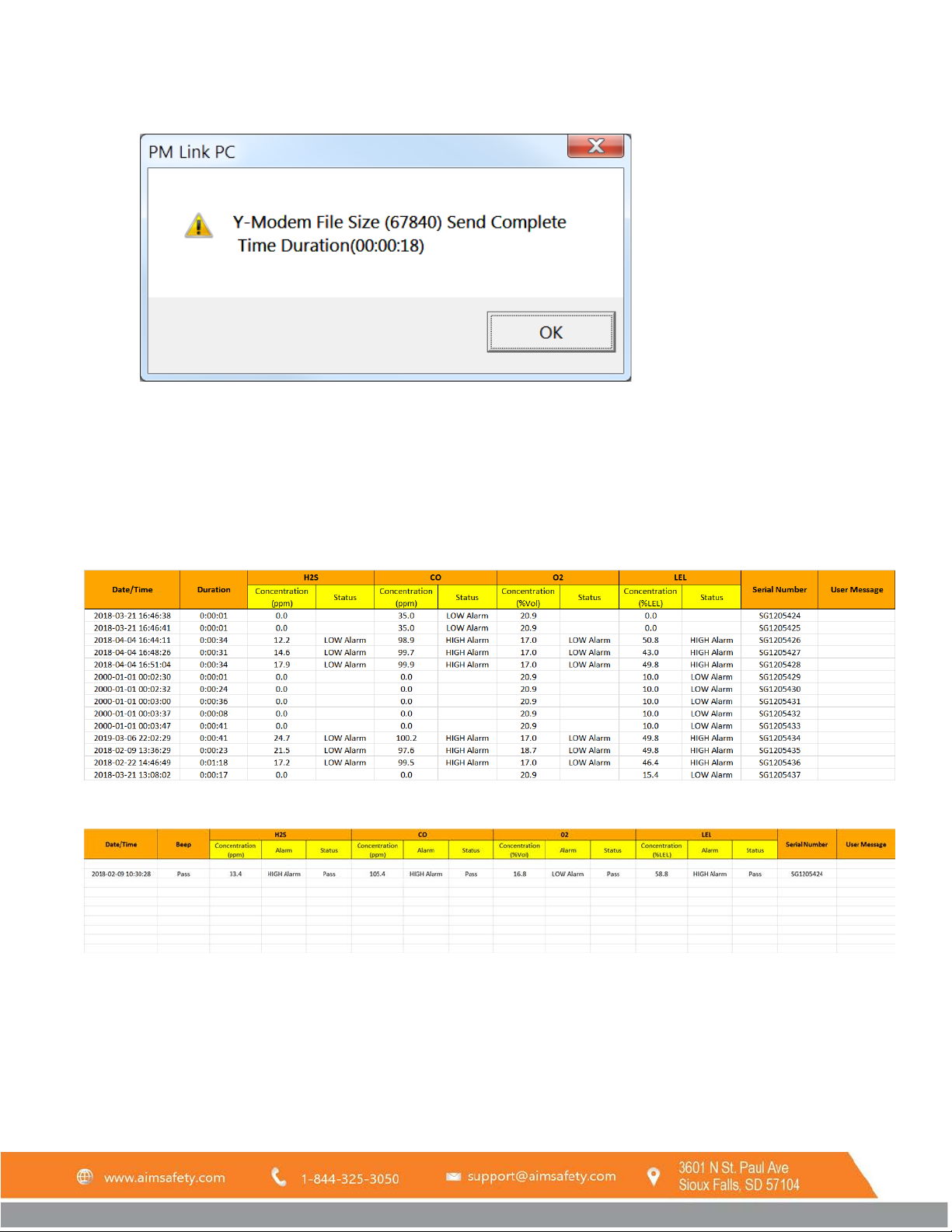
7. A window will popup when the download is complete. Click OK to resume other operations.
6.2.2 View Log Files
The log file can be viewed using spreadsheet software.
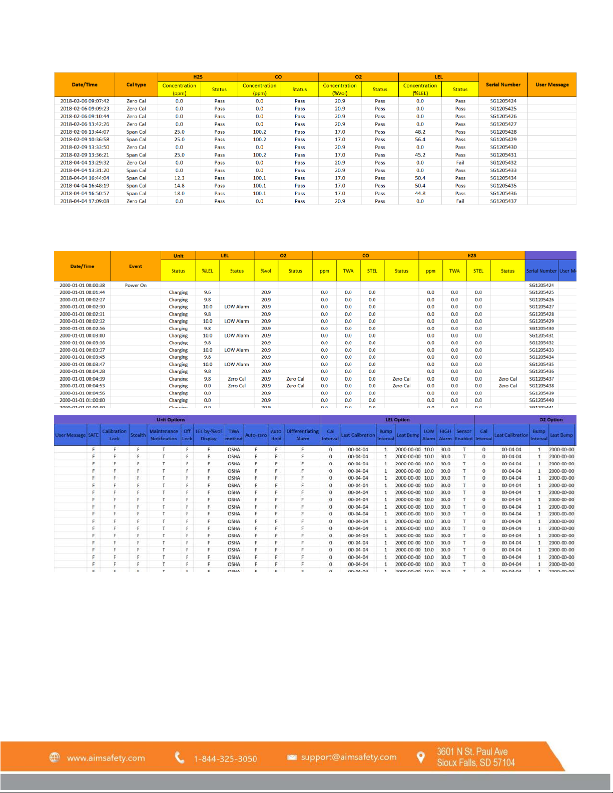
The “Event Log” spreadsheet will include tabs for Event Log, Bump Log, and Calibration Log. The “Event + Data Log”
spreadsheet includes the same tabs for Event Log, Bump Log, and Calibration Log. It also includes an additional Data
Log tab.
The Event Log (see below) tab shows a log of each alarm event.
The Bump Log (see below) tab shows a log of each bump test.
The Calibration Log (see below) tab shows a log of each calibration (zero and span calibration).
REV – 1.0 [34-2900-0510-4] 35 | Page
Page 36
PM Link User Manual
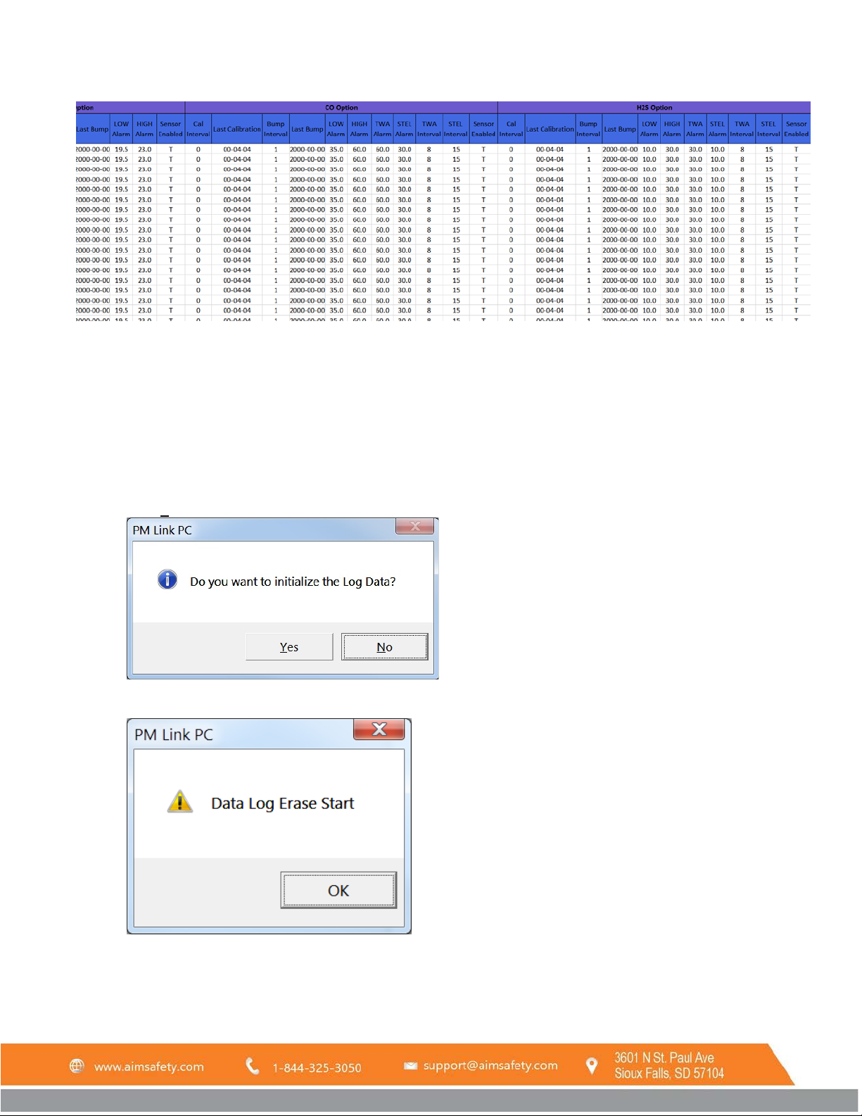
The Data Log (see 3 images below) tab shows a log of all configurable settings and sensor readings each time any
data is logged.
REV – 1.0 [34-2900-0510-4] 36 | Page
Page 37
PM Link User Manual
6.2.3 Erase Log Data
This operation will erase the stored log data on the PM
previously saved to the computer.
To erase the stored log data:
monitor. It will not erase any log files which were
400
Confirm the PM
1.
monitor is positioned correctly to communicate with the PM Link hardware.
400
2. Select Log Erase from the Tools dropdown menu.
Alternatively, click LOG in the Tool section of the interface. Then, click Erase.
3. Click Yes to erase the Log Data.
4. The data is erased. Click OK to resume other operations.
REV – 1.0 [34-2900-0510-4] 37 | Page
Page 38

PM Link User Manual
7 Product limited warranty
AimSafety warrants this product will be free from defective materials and workmanship for a period of two (2) years from date of
manufacture, provided it is maintained and used in accordance with AimSafety instructions and/or recommendations. If any
component becomes defective during the warranty period, it will be replaced or repaired free of charge, if the unit is returned in
accordance with the instructions below. This warranty does not apply to units that have been altered or had repair attempted, or
that have been subjected to abuse, accidental or otherwise. The above warranty is in lieu of all other express warranties,
obligations or liabilities. THE IMPLIED WARRANTIES OF MERCHANTABILITY AND FITNESS FOR PARTICULAR PURPOSE
ARE LIMITED TO A PERIOD OF TWO (2) YEARS FROM THE PURCHASE DATE. AimSafety shall not be liable for any incidental
or consequential damages for breach of this or any other warranty, express or implied, arising out of or related to the use of said
gas PM monitor. Manufacturer or its agent’s liability shall be limited to replacement or repair as set forth above. Buyer’s sole and
exclusive remedies are return of the goods and repayment of the price, or repair and replacement of non-conforming goods or
parts.
Warranty Procedure
Contact the local AimSafety authorized reseller or AimSafety Technical Support to obtain a Return Materials
Authorization (RMA).
AimSafety by Macurco
3601 N. St. Paul Avenue
Sioux Falls, SD 57104
Technical Support Contact Information
Phone: 1-844-325-3050
Fax: 1-605-951-9616
Email: [email protected]
Website: www.support.aimsafety.com
Rev - 1.0
Issue Date: 3-17-2019
Document No: 34-2900-0510-4
© Aerionics 2018. All rights reserved.
Macurco is a trademark of Aerionics, Inc.
General Contact Information
Phone : 1-877-367-7891
Fax : 1-605-951-9616
Email : [email protected]
Website: www.aimsafety.com
REV – 1.0 [34-2900-0510-4] 38 | Page
 Loading...