

AIM AT1741 Datasheet
AT1741
2-Channel PWM Controller for CCFL Backlight
Features
• High-accuracy reference voltage circuit (±2%).
• Built-in short-circuit protection circuit.
• Built-in Undervoltage Lockout protection.
• Internal 2.5V Reference supply.
• Variable Dead time provides control over total
Range.
Applications
• LCD CCFL Backlight
• Portable equipment
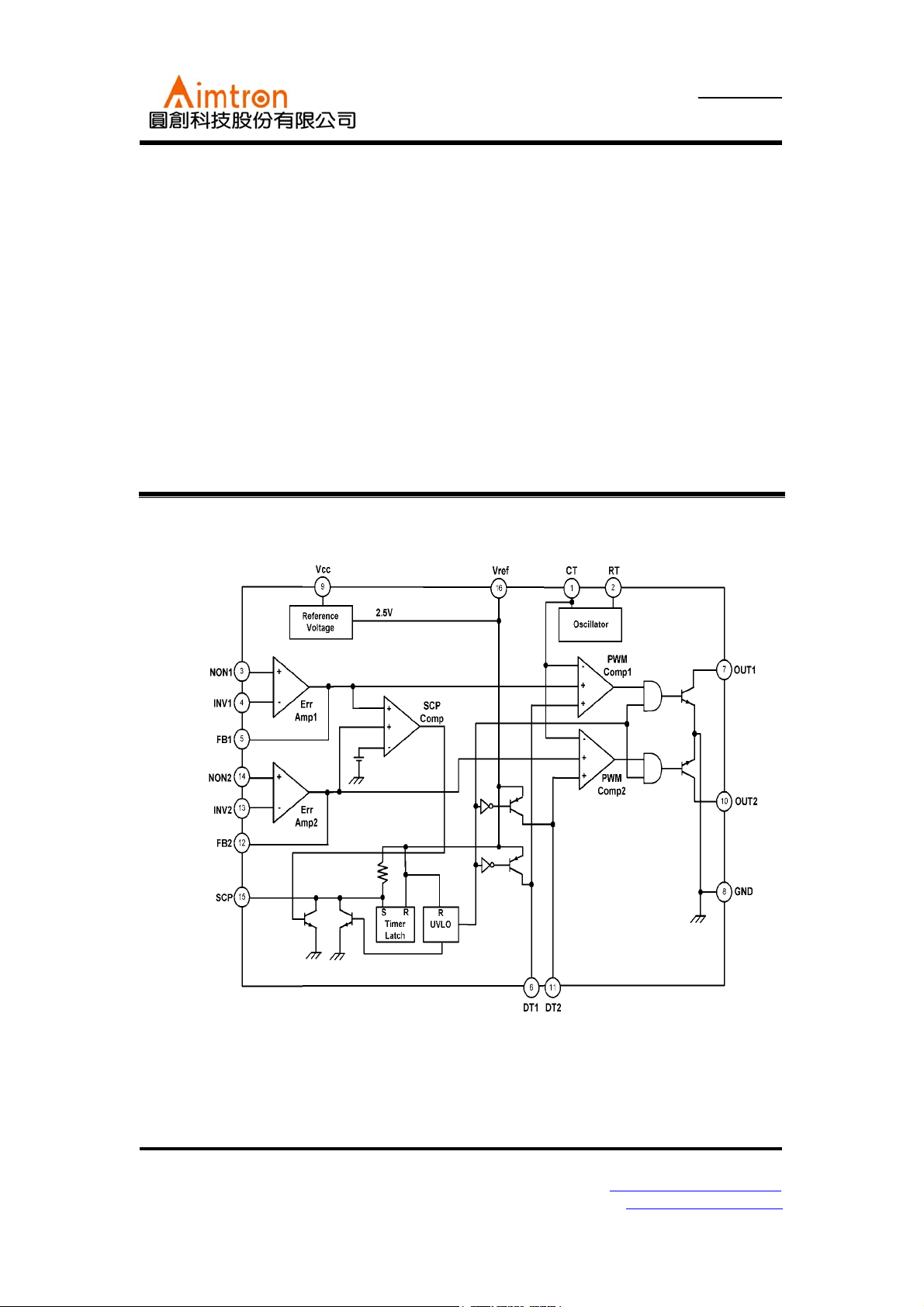
Block Diagram
General Description
The AT1741 is 2-channel PWM switching
regulator controllers that contains an on-chip 2.5V
reference, two error amplifier, an adjustable
oscillator, two dead-time comparators, undervoltage lockout circuitry and 2 common-emitter
output. It is idea for step-up, step-down, and
inverting converter.
2F, No.10, Prosperity RD. II, Science-Based Industrial Park, Hsinchu 300,Taiwan, R.O.C.
Tel: 886-3-563-0878 WWW: http://www.aimtron.com.tw
Fax: 886-3-563-0879 Email: service@aimtron.com.tw
1
AT1741
2-Channel PWM Controller for CCFL Backlight
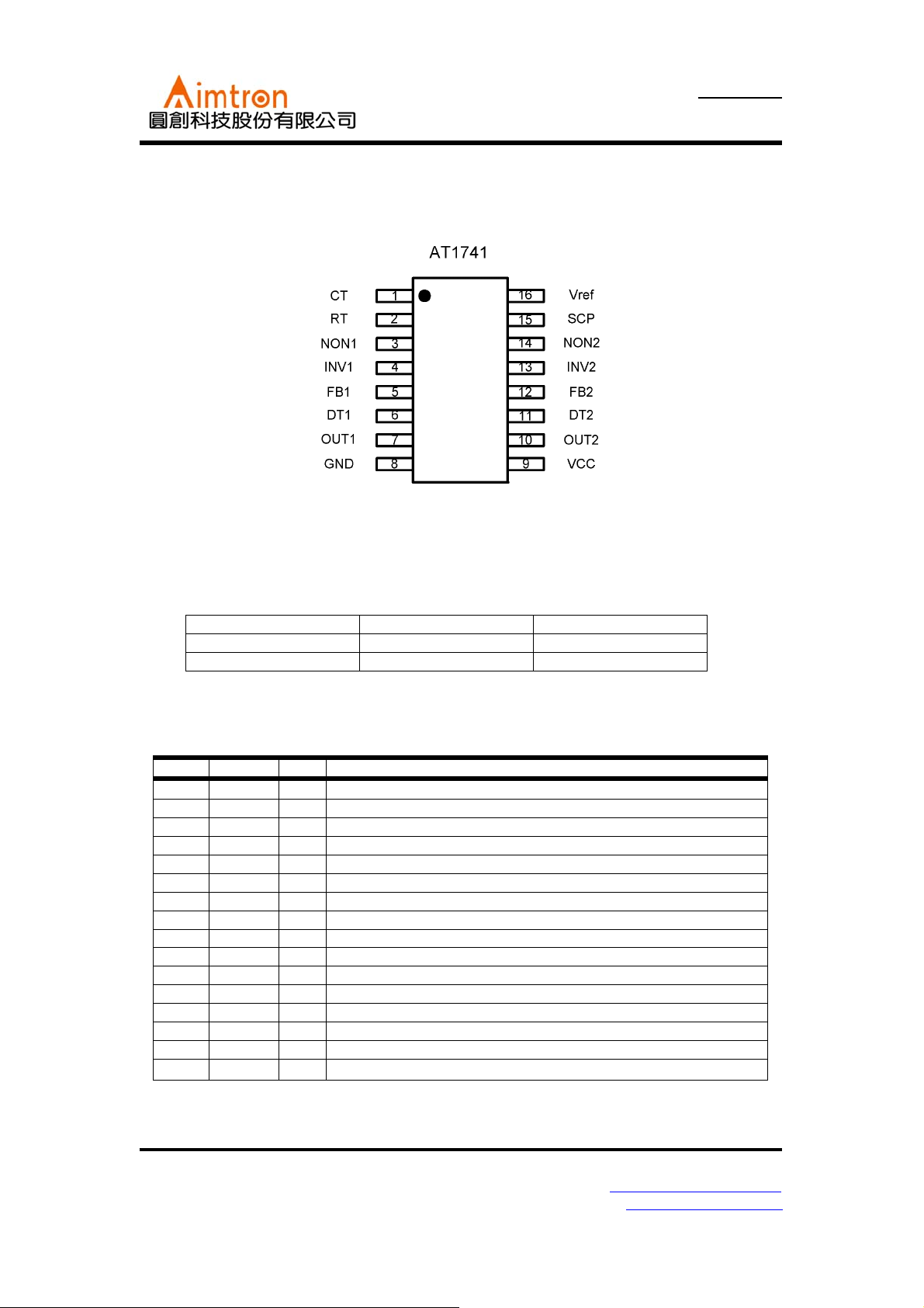
Pin Configuration
Ordering Information
Part number Package Marking
AT1741 SOP16 AT1741S
---
Pin Description
Pin No. Symbol I/O Description
1 CT -- External timing capacitor
2 RT -- External timing resistor
3 NON1 I Positive input for error amplifier 1
4 INV1 I Negative input for error amplifier 1
5 FB1 O Error amplifier 1 output
6 DT1 I Output 1 dead time / soft start setting
7 OUT1 O Output 1
8 GND -- Ground
9 Vcc -- Power supply
10 OUT2 O Output 2
11 DT2 I Output 2 dead time / soft start setting
12 FB2 O Error amplifier 2 output
13 INV2 I Negative input for error amplifier 2
14 NON2 I Positive input for error amplifier 2
15 SCP -- Time latch setting
16 Vref O
Reference voltage output(2.5V)
2F, No.10, Prosperity RD. II, Science-Based Industrial Park, Hsinchu 300,Taiwan, R.O.C.
Tel: 886-3-563-0878 WWW: http://www.aimtron.com.tw
Fax: 886-3-563-0879 Email: service@aimtron.com.tw
2
AT1741
2-Channel PWM Controller for CCFL Backlight
Absolute Maximum Ratings
(Ta=+250C)
Parameter Symbol
Power supply voltage Vcc 30 V
Power dissipation Pd 500*
Operating temperture Topr -30~+85
Storage temperture Tstg -55~+125
Output current Io 120*
Output voltage Vo 30
*1 When mounted on 70mm×70mm×1.6mm glass epoxy board. Reduced by 6.5mw for each increase in Ta of 1℃ over 25℃.
*2 Should not exceed Pd and values.
Limits
Unit
1
mW
℃
℃
2
mA
V
Recommended Operating Conditions
(Ta=+250C)
Va lu esParameter Symbol
Min. Typ. Max.
Power supply voltage V
CC
3.6 6.0 25
Output current Io -- -- 100 mA
Output voltage Vo -- -- 25 V
Error amplifier input voltage V
Timing capacitor C
Timing resistor
Oscillator frequency F
OM
CT
R
RT
OSC
0.3 -- 1.6 V
100 -- 15000 pF
5.1 -- 50
10 -- 800 kHz
Unit
V
kΩ
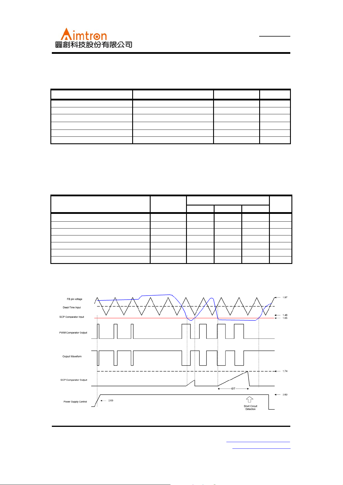
Timing chart
2F, No.10, Prosperity RD. II, Science-Based Industrial Park, Hsinchu 300,Taiwan, R.O.C.
Tel: 886-3-563-0878 WWW: http://www.aimtron.com.tw
Fax: 886-3-563-0879 Email: service@aimtron.com.tw
3
 Loading...