

Page 1

Lynx
Server Motherboard
User's Manual
UM_Lynx_v3.1_041119
Page 2

Table of Contents
Preface ������������������������������������������������������������������������������������������������ ii
Safety Instructions ����������������������������������������������������������������������������� iii
About This Manual ������������������������������������������������������������������������������ iv
Chapter 1� Product Features ��������������������������������������������������������������1
1�1 Componenets �����������������������������������������������������������������������������������1
1.2 Specications ����������������������������������������������������������������������������������� 2
1�3 Feature ���������������������������������������������������������������������������������������������3
Chapter 2� Hardware Setup ����������������������������������������������������������������4
2�1 Central Processiong Unit Setup ���������������������������������������������������������4
2.1.1 Processor Support ..............................................................................................4
2.1.2 Processor Heat Sink Module and Processor Socket Assembly .......................5
2.1.3 Processor Heat Sink Module ..............................................................................6
2�2 System Memory Setup ���������������������������������������������������������������������� 9
2.2.1 DIMM Installation ...............................................................................................9
2.2.2 DIMM Location ................................................................................................ 10
2.2.3 DIMM Slot Installation Order........................................................................... 11
Chapter 3� Hardware Settings ����������������������������������������������������������14
3�1 Motherboard Block Diagram ������������������������������������������������������������14
3�2 Motherboard Content List ���������������������������������������������������������������15
3�3 Motherboard Layout ������������������������������������������������������������������������17
3�4 Connector and Jumper �������������������������������������������������������������������� 18
3�5 System LED Indicator ����������������������������������������������������������������������27
3.5.1 Internal LED ...................................................................................................... 27
Chapter 4. BIOS Conguration Settings ������������������������������������������� 28
4�1 Navigation Keys ������������������������������������������������������������������������������ 28
4�2 BIOS Menu ��������������������������������������������������������������������������������������29
4.2.2 Startup .............................................................................................................. 29
4.2.3 Update .............................................................................................................. 32
4�3 Main ����������������������������������������������������������������������������������������������34
4.3.1 Main .................................................................................................................. 34
4�4 Advanced ���������������������������������������������������������������������������������������� 35
4.4.1 Boot Conguration .......................................................................................... 35
4.4.2 Peripheral Conguration ................................................................................. 36
4.4.3 Video Conguration ......................................................................................... 36
4.4.4 ACPI Table/Features Control ........................................................................... 36
Content
Page 3

4.4.5 System Event Log ............................................................................................ 36
4.4.6 Debug Conguration........................................................................................ 39
4.4.7 OEMBOARD Function ...................................................................................... 39
4.4.8 SIO AST2500 ................................................................................................... 39
4.4.9 Socket Conguration ...................................................................................... 40
4.4.10 ME Conguration ........................................................................................... 51
4.4.11 PCH Conguration ......................................................................................... 53
4.4.12 H2O IPMI Conguration ................................................................................ 58
4.4.13 APEI Conguration ....................................................................................... 58
4.4.14 Console Redirection Setup ............................................................................ 59
4�5 Security ������������������������������������������������������������������������������������������60
4.5.1 Security ............................................................................................................ 60
4�6 Power ���������������������������������������������������������������������������������������������61
4.6.1 Power ............................................................................................................... 61
4�7 Boot ������������������������������������������������������������������������������������������������62
4.7.1 Boot .................................................................................................................. 62
4�8 Exit �������������������������������������������������������������������������������������������������63
4.8.1 Exit .................................................................................................................... 63
Chapter 5. BMC Conguration Settings �������������������������������������������� 64
5�1 Login ����������������������������������������������������������������������������������������������64
5�2 Web GUI ���������������������������������������������������������������������������������������� 65
5.2.1 Menu Bar .......................................................................................................... 65
5.2.2 User Information and Quick Button ............................................................... 66
5.2.3 Dashboard ........................................................................................................ 67
5.2.4 Sensor .............................................................................................................. 67
5.2.5 FRU Information ............................................................................................... 68
5.2.6 Logs and Reports ............................................................................................ 69
5.2.7 Settings ............................................................................................................ 70
5.2.8 Remote Control ................................................................................................ 72
5.2.9 Power Control .................................................................................................. 76
5.2.10 Maintenance .................................................................................................. 77
5.2.11 Sign out .......................................................................................................... 79
5�3 Firmware Update �����������������������������������������������������������������������������80
Chapter 6� Technical Support ����������������������������������������������������������� 81
Content
Page 4

Copyright © 2018 AIC, Inc� All Rights Reserved�
This document contains proprietary information about
AIC products and is not to be disclosed or used except in
accordance with applicable agreements.
Page 5

Document Release History
Release Date Version Update Content
November
2017
March
2018
January
2019
April
2019
1 User's Manual release to public
2
3
3.1 BIOS update.
1. Gramnar Errors
2. Add About this Manual
1. Datasheet
2. Hardware Settings update
3. SW update
i
Page 6

Preface
Copyright
No part of this publication may be reproduced, stored in a retrieval system, or transmitted
in any form or by any means, electronic, mechanical, photo-static, recording or otherwise,
without the prior written consent of the manufacturer.
Trademarks
All products and trade names used in this document are trademarks or registered
trademarks of their respective holders.
Changes
The material in this document is for information purposes only and is subject to change
without notice.
Warning
1. A shielded-type power cord is required in order to meet FCC emission limits and also
to prevent interference to the nearby radio and television reception. It is essential that
only the supplied power cord be used.
2. Use only shielded cables to connect I/O devices to this equipment.
3. You are cautioned that changes or modications not expressly approved by the party
responsible for compliance could void your authority to operate the equipment.
Disclaimer
AIC shall not be liable for technical or editorial errors or omissions contained herein.
The information provided is provided "as is" without warranty of any kind. To the extent
permitted by law, neither AIC or its afliates, subcontractors or suppliers will be liable
for incidental, special or consequential damages including downtime cost; lost prots;
damages relating to the procurement of substitute products or services; or damages
for loss of data, or software restoration. The information in this document is subject to
change without notice.
ii
Page 7

Safety Instructions
When installing, operating, or performing maintenance on this equipment, the following
safety precautions should always be observed in order to reduce the risk of fire, electric
shock, and personal injury.
Read and understand all instructions.
Observe warnings and instructions marked on the product.
• For proper mounting instructions, please consult the User’s Manual provided with this
product.
• Do NOT place this product on an unstable cart, stand, table or uneven surface that
might cause the product to fall and sustain serious damage.
• Only install the equipment identified in the User’s Manual. Use of other equipment could
cause improper connection of circuitry and may result in fire or personal injury.
• This product should only be operated with the type of power source indicated on the
marked label. If you are uncertain about which type of power supply is used in your
area, consult your dealer or local Power Company.
• Disconnect the power supply module before removing power from the system. Unplug
this product from the wall outlet before cleaning. Use a damp cloth for cleaning. Do not
use liquid cleaners or aerosol cleaners.
• Do not use this product near a water source, such as a faucet.
• Never spill liquids of any kind on this product.
• Never shove objects of any kind into this product’s open slots, as they may touch
dangerous voltage points or short out parts and could result in fire or electric shock.
• Do not block or cover slots and openings in this unit, as they were made for ventilation
and prevent this unit from overheating. Do not place this product in a built-in installation
unless proper ventilation is available.
• Do not disassemble this product. This product should only be taken apart by trained
personnel. Opening or removing covers and circuit boards may expose you to electric
shock or other risks. Incorrect reassembly can also cause electric shock when the unit
is subsequently used.
• Risk of explosion is possible if battery is replaced with an incompatible type. Dispose
of used batteries accordingly.
• This product is equipped with a three-wire grounding type plug, a plug with a third
(grounding) pin. As a safety feature, this plug is intended to fit only into a grounding
type power outlet. If you are unable to insert the plug into the outlet, contact your
electrician to replace the outlet. Do not remove the grounding type plug or use a 3-Prong
To 2-Prong Adapter to circumvent the safety feature; doing so may result in electric
shock and/or damage to this product.
iii
Page 8

About This Manual
Thank you for selecting and purchasing the Lynx Serverboard.
This user's manual is provided for professional technicians to perform easy hardware
setup, basic system configurations, and quick software startup. This document pellucidly
presents a brief overview of the product design, device installation, and firmware settings
for the Lynx motherboard. For the latest version of this user's manual, please refer to the
AIC website: http://www.aicipc.com/en/productdetail/20870.
Chapter 1 Product Features
This chapter delivers the overall layout of the product, including the fundamental
components on the motherboard, design specifications, and noteworthy features. Lynx is
an ideal server grade motherboard that is specifically designed to accommodate diverse
enterprises for managing heavy workloads, databases, nearline applications, and cloud
deployments. This product supports the Intel® Xeon® Scalable Processors (Skylake
and next generation CPU) and Socket P0 (LGA-3647) with a memory support 24 DDR4
2400/2666 MHz DIMM accross 6 channels per CPU.
Chapter 2 Hardware Setup
This chapter displays an easy installation guide for assembling the CPU (Central
Processing Unit) and memory module. Utmost caution for proceeding to set up the
hardware is highly advised. The components on the motherboard are highly fragile and
vulnerable to exterior influence. Do not attempt to endanger the device by placing the
device in a potentially unstable or hazardous surroundings, including positioning the device
on an uneven grounds or humid environments.
Chapter 3 Motherboard Settings
This chapter elaborates the overall layout of the server motherboard, including multifarious
connectors, jumpers, and LED descriptions. These descriptions assist users to configure
different settings and functions of the motherboard, as well as to confirm the location of
each connector and jumper.
Chapter 4 BIOS Configuration Settings
This chapter introduces the key features of BIOS, including the descriptions and option
keys for diverse functions. These details provide users to effortlessly navigate and
configure the input/output devices.
Chapter 5 BMC Configuration Settings
This chapter illustrates the diverse functions of IPMI BMC, including the details on logging
into the web page and assorted definitions. These descriptions are helpful in configuring
various functions through Web GUI without entering the BIOS setup. For more information
of BMC configurations, please refer to BMC (Aspeed2500) User's Manual for a more
detailed description.
Chapter 6 Technical Support
For more information or suggestion, please contact the nearest AIC corporation
representative in your district or visit the AIC website: http://www.aicipc.com/en. It is our
greatest honor to provide the best service for our customers.
iv
Page 9
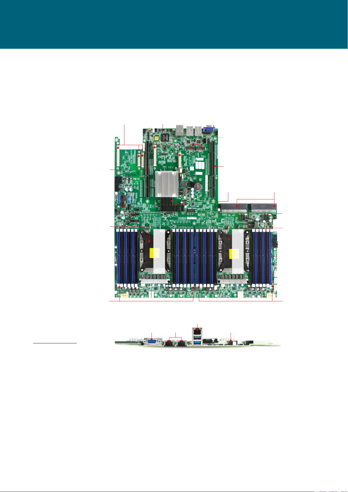
Spica User Manual
inches : 16.7 x 17
OCP Mezzanine V2.0 (A+B)
OCP Mezzanine V2.0 (A+B+C)
LGA3647 Socket P0 for Intel®
Chapter 1� Product Features
1�1 Componenets
Lynx
Chapter 1. Product FeaturesLynx User Manual
Support PCIe Gen3 x16
(Share with Max I/O® #1)
AIC Max I/O® #1; (CPU0)
PCIe Gen3 Supports 48 Lanes
(Share with OCP Mezzanine)
LGA3647 Socket P0 for Intel®
Xeon® Processor Skylake-SP
(CPU0)
Support PCIe Gen3 x16
(Share with Max I/O® #2)
2 x NGFF(M.2) M-Key
(2280, 2242 by additional
bracket) support SATA/
PCIe x2
AIC Max I/O® #2; (CPU1)
PCIe Gen3 Supports 48 Lanes
(Share with OCP Mezzanine)
Intel® Storm Lake 100Gbps
12V Single Power-in
Interface Supports CRPS
4 x 12V AUX Power Output
Xeon® Processor Skylake-SP
(CPU1)
10 x SATA 3.0
Connectors
Intel® Storm Lake 100Gbps
Host Fabric Interface
Host Fabric Interface
12 x DDR4 DIMM Slots
6 Channels (for CPU0)
2 x USB 3.0 + RJ45
Dimensions
mm : 424.18 x 431.8
VGA Port
Dedicated NIC for BMC
2 x RJ45
Serial Console
by MicroUSB
Product specifications and features are subject to change without prior notice�
12 x DDR4 DIMM Slots
6 Channels (for CPU1)
1
Page 10
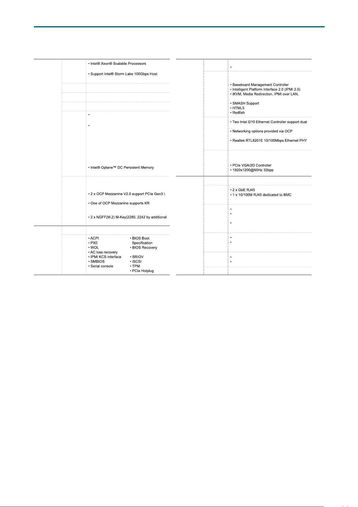
LYNX
1.2 Specications
Chapter 1. Product FeaturesLynx User Manual
System
System BIOS
Processor
Support
CPU TDP
UPI Speeds
Socket Type
System
Memory
Expansion
Slots
BIOS Type
BIOS
Features
(Skylake and next gen. CPU)
Fabric Interface, Skylake-F SKU CPU
205W
10.4 GT/s, 9.6 GT/s
Socket P0 (LGA-3647 Socket)
6 x memory channels per CPU,
2 x DIMM per channel
24 x DIMM slots support:
DDR4 2400/2666MHz RDIMM/LRDIMM
(feature supports up to DDR4 2933MHz
by next gen. process upgrade)
- up to 384GB RDIMM SRx4
- up to 768GB RDIMM DRx4
- up to 3072GB RDIMM 3DS 8Rx4/QRx4
- up to 1536GB LRDIMM QRx4
- up to 3072GB LRDIMM 3DS 8Rx4//QRx4
(Apache Pass) support
2 x AIC Max I/O® support:
PCIe Gen3 total 96 lanes;
(each 48 lanes from CPU0 & CPU1)
x16 (share with Max I/O®)
(optional by PCH C624/C622 SKUs), as 10GbE
(KR/SFI/XFI) or 1GbE (KX)
bracket) support SATA/PCIe x2
Insyde UEFI BIOS
Mode
redirection
On-board
Devices
Input/Output
SATA
BMC
Network
Controller
Graphics
Serial ATA
LAN
USB
VGA
Serial Port
Others
Intel® Lewisburg PCH on-chip solution
10 x SATA 6.0 Gb/s
Aspeed AST2500 Advanced PCIe Graphics &
Remote Management Processor
Serial over LAN
port GbE RJ45 connectors
Mezzanine extension
for BMC dedicated management port
Aspeed AST2500 Advanced PCIe Graphics &
Remote Management Processor
10 x SATA 6.0 Gb/s ports
management
2 x USB 3.0 Type-A connectors
2 x USB internal pin-header to support total
4 x USB3.0/USB2.0
1 x USB internal pin-header to support 2 x
USB 2.0
1 x external VGA port
1 x internal VGA pin-header
(share with external VGA port)
1 x external Micro-USB type B for COM port
2 x internal COM pin-headers
1 x TPM 2.0 onboard
2
Page 11

Chapter 1. Product FeaturesLynx User Manual
1�3 Feature
The Lynx server board offers the latest Intel® Xeon® Scalable Processors technology
solutions with compelling performance and provides premium power and communications
infrastructure).
By implementing Intel® Xeon® Scalable Processors, fully integrated microarchitecture
with AIC MAX I/O® 2.0 which support up to 96 lanes of PCIe Gen3, Lynx server board can
maximize your I/O intensive application demand, providing six channels per CPU with
total twenty-four DIMM slots deployment which can support up to DDR4 2400/2666MHz
(feature supports up to DDR4 2933MHz by next gen. process upgrade).
Featured with ground breaking technologies including Intel® Next Generation
Microarchitecture and Instruction Set (AVX-512, VMD, QAT - optional by PCH SKU), Speed
Shift Technology, UPI link speeds up to 10.4GT/s, the Lynx server board enable next
generation server solutions with an incredible leap in performance.
• Supports Intel® Xeon® Scalable Processors for highest server performance and
improved power efficiency
• Supports 24 DDR4 DIMM slots for maximun memory performance
• AIC Max I/O® supports up to 96 PCIe Gen3 lanes (48 lanes from CPU0 + 48 lanes from
CPU1); both 16 lanes will be shared with OCP Mezzanine V2.0
• Supports two OCP Mezzaine V2.0 up to PCIe Gen3 x16 extension (Shared from Max I/
O®)
• Onboard dual GbE ports come from 2 x Intel® Ethernet Controller I210
• Supports two CRPS PSU direct connection for power input
• Onboard Baseboard Management Controller for system management and IPMI control
• Embedded components for 5+year long life
3
Page 12
Spica User Manual
Chapter 2. Hardware SetupLynx User Manual
Chapter 2� Hardware Setup
2�1 Central Processiong Unit Setup
2�1�1 Processor Support
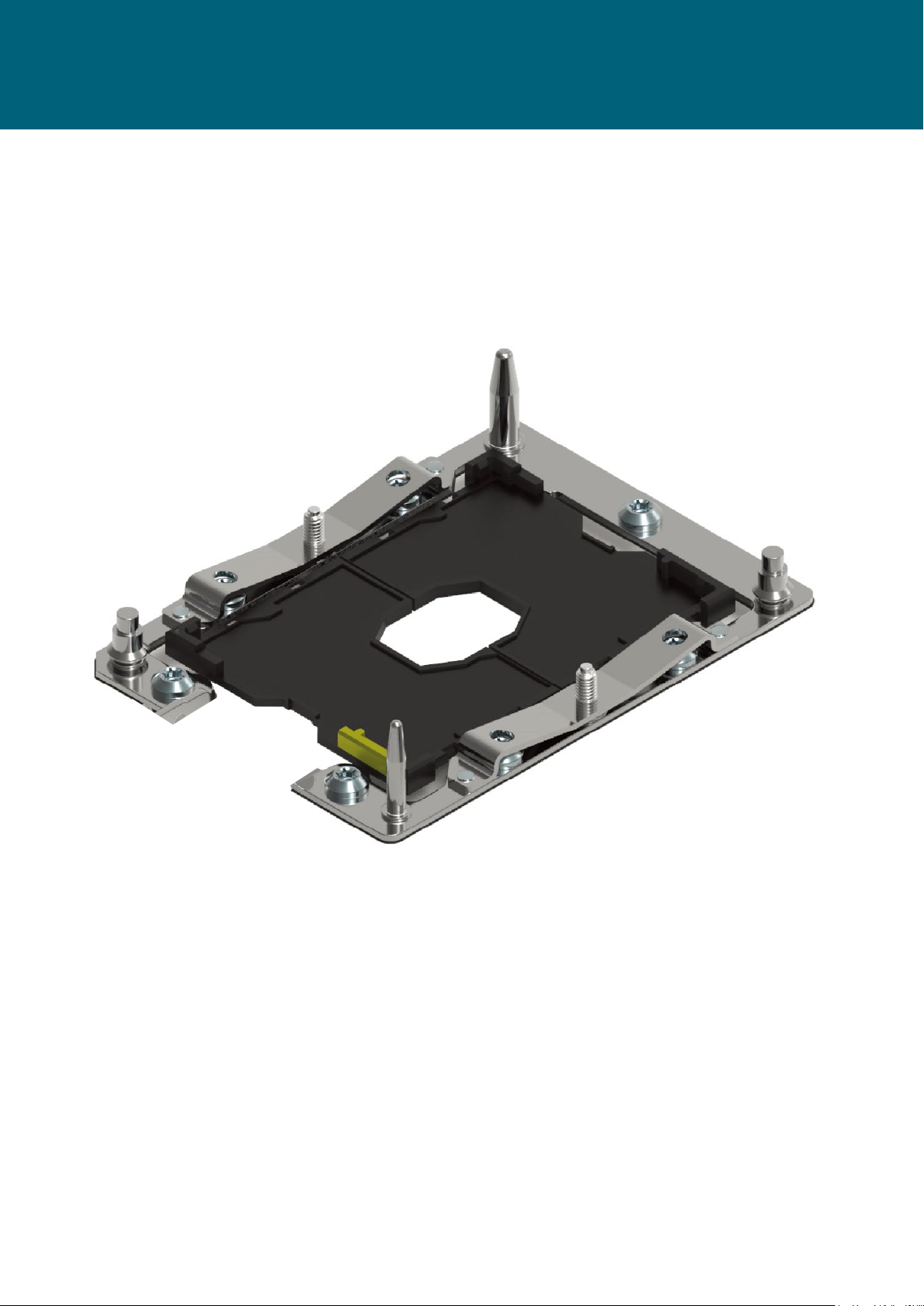
The server board includes two processor sockets (LGA-3647) that provides support for
Intel® Xeon® Processor Scalable Family processor and a Thermal Design Power (TDP) of up
to 165W on selected models.
4
Page 13
Chapter 2. Hardware SetupLynx User Manual
2�1�2 Processor Heat Sink Module and Processor Socket Assembly
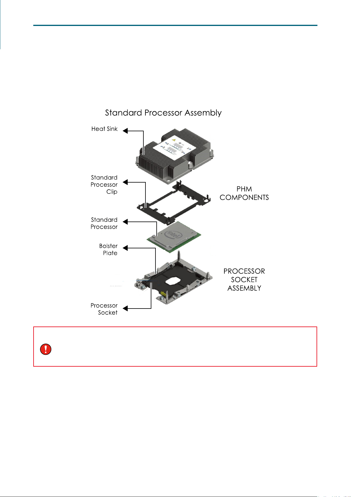
Each processor socket on the server board is pre-assembled with a loading mechanism that
is designed to secure the Processor Heat Sink Module (PHM) to the server board as shown
below.
WARNING
Previous generations of the Intel Xeon Processors and heatsinks are not compatible with the
Intel Server Board S2600BP Product Family. Processor installation requires that the processor
be attached to the installation onto the server board.
5
Page 14
Chapter 2. Hardware SetupLynx User Manual
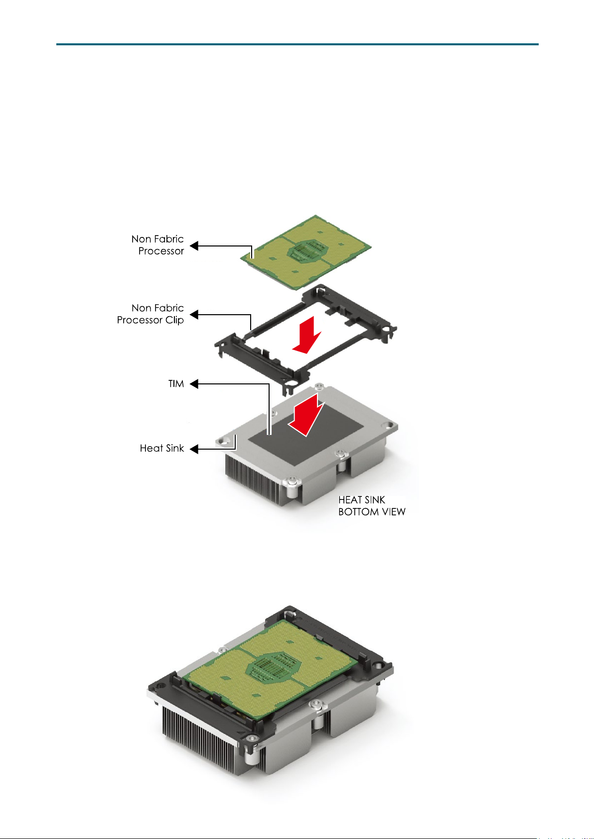
2�1�3 Processor Heat Sink Module
The PHM refers to the sub-assembly where the heat sink and processor are clipped
together onto the server board prior to installation. The PHM consists of the
components shown below.
Processor Heat Sink Module (PHM) Sub-Assembly
Processor Heatsink Module (PHM)
6
Page 15
Chapter 2. Hardware SetupLynx User Manual
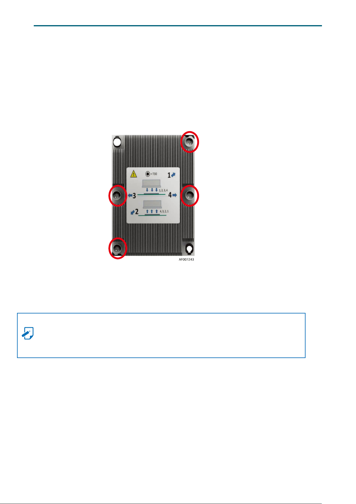
The PHM sits level with the processor socket assembly. The PHM is NOT installed
properly if it does not sit level with the processor socket assembly. Once the PHM is
seated over the processor socket assembly, the four heat sink torque screws must be
tightened in order as shown below.
Processor Heat Sink – Top View with Screw Tightening Order
NOTE
Failure to tighten the heatsink screws in the specified order may cause damage to the
processor socket assembly. Heat sink screws should be tighted to 12 in-lbs torque
according to the indicated order on the top of the heatsink label.
7
Page 16
Chapter 2. Hardware SetupLynx User Manual
r
4. Connect another end of
the HFI cable to the
connector(A)
of the HFI card.
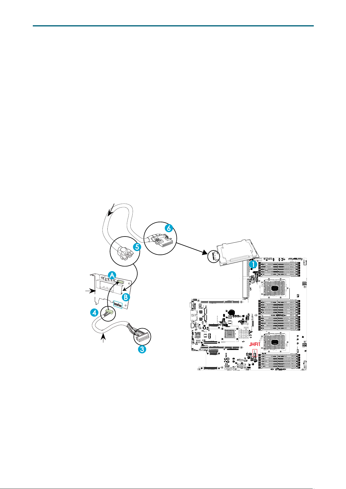
2�2 HFI Carrier Card for Host Fabric Interface (HFI) Supported
The Intel® Fabric Passive (IFP) Internal Cable Assembly enables high speed, low loss data
connections between the Intel® Xeon™ Phi™ processor (KNL-F) and chassis connections to
an external network interface via QSFP +28 style connectors. IFP internal cable assembly
enables a direct connection from an Intel processor to an Intel Fabric network.
Installation Instructions
1. Locate the CPU Socket on the motherboard. Install an Fabric processor on this socket as
shown below (marked 1) if you have not done so.
2. Locate the PCI-E slots the motherboard. Install an Host Fabric Interface (HFI) card on an
appropriate PCI-E slot of your choice.
3. Connect the HFI connector on the HFI cable to the JHFI1 header as show below (marked
3).
4. Connect the other end of the HFI cable to the connector (marked A) on the HFI card as
shown below. (Marked 4 ).
5. Connect the plug (marked 5) on one end of the Internal_Faceplate_to_the_Processor (IFP)
cable to the connector (marked B ) on the HFI card as shown below.
6. Connect the other end of IFP cable (marked 6) to the Fabric processor installed in CPU
Socket as shown below.
H
FI Carrier Card
HFI Carrier Card
(Host Fabric Interface)
Sideband Cable
HFI
6. Connect the other end of the
IFP cable to the Fabric Processor.
5. Connect one end of the
IFP cable to the connector(B)
of the HFI card.
2. Install an HFI card to a PCI-E slot
3. Connect the HFI connector
on the HFI cable to the onboard
JHFI1 header.
• Cards & Cables are not included in the range of supply�
Fabric Processor
Install an Fabric Processo
JHFI1
• HFI Drawing example�
8
Page 17
Chapter 2. Hardware SetupLynx User Manual
DIMM n
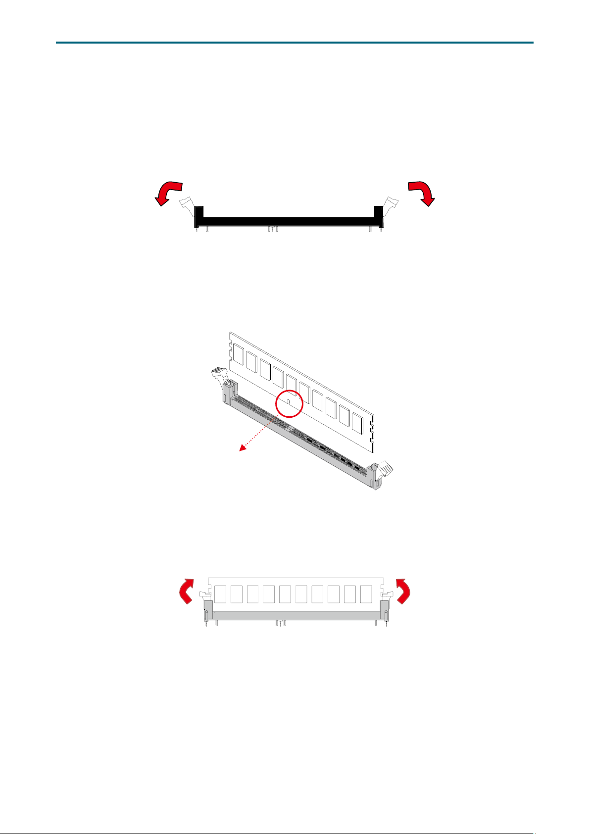
2�2 System Memory Setup
This server board supports 24 DDR4 2400/2666 Registered ECC SDRAM(RDIMM) / LoadReduced DIMM (LRDIMM).
2�2�1 DIMM Installation
Step 1 Unlock the dimm socket by pressing the retaining clips outward.
Step 2 Insert the memory module into the slot. Make sure that the dimm notch is
accurately positioned.
otch
Step 3 Close the retaining clips to complete installation.
9
Page 18
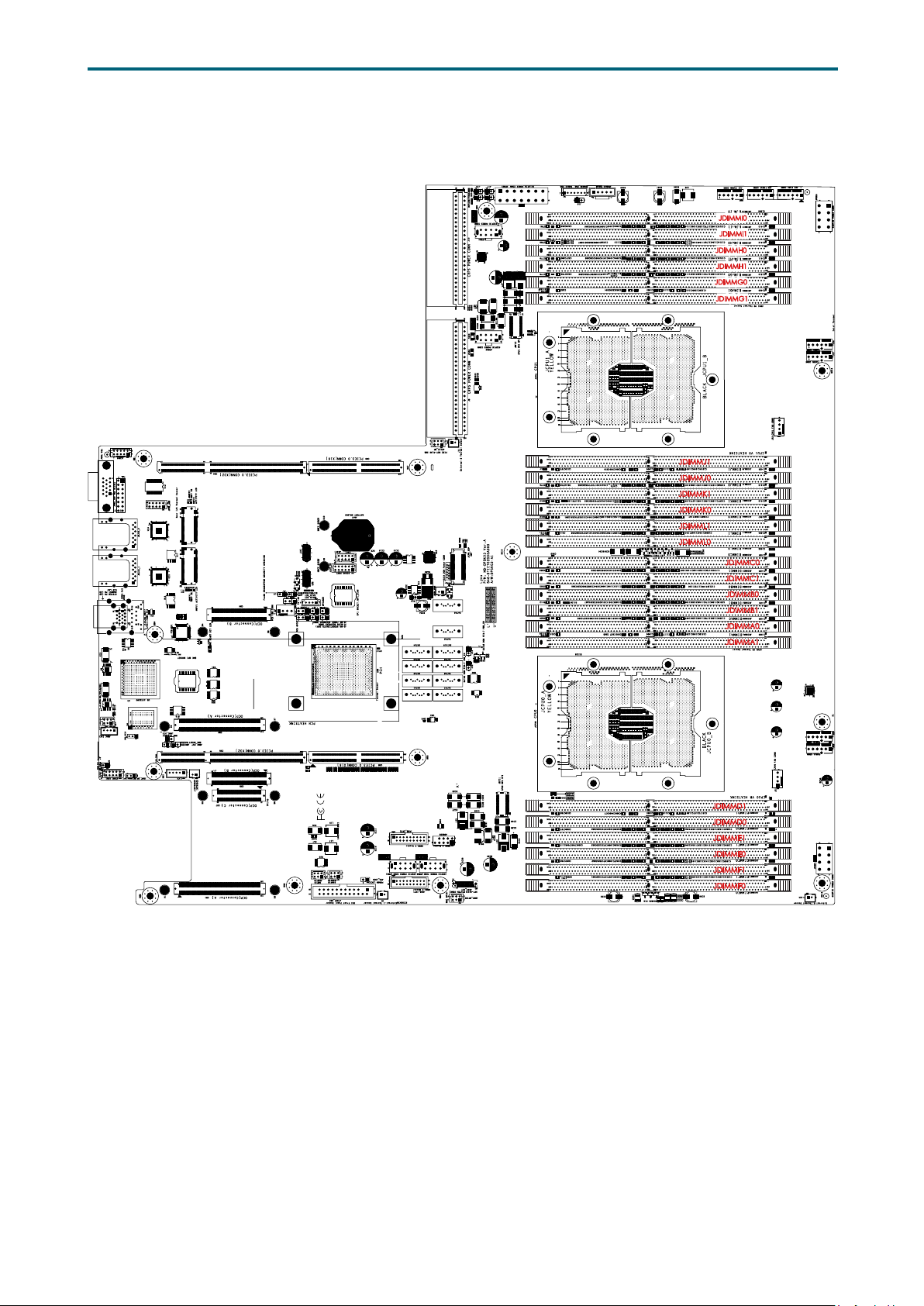
2�2�2 DIMM Location
Chapter 2. Hardware SetupLynx User Manual
CPU1
JDIMMJ1
JDIMMJ0
JDIMMK1
JDIMMK0
JDIMML1
JDIMML0
JDIMMC0
JDIMMC1
JDIMMB0
JDIMMB1
JDIMMA0
JDIMMA1
CPU0
JDIMMD1
JDIMMD0
JDIMME1
JDIMME0
JDIMMF1
JDIMMF0
10
Page 19
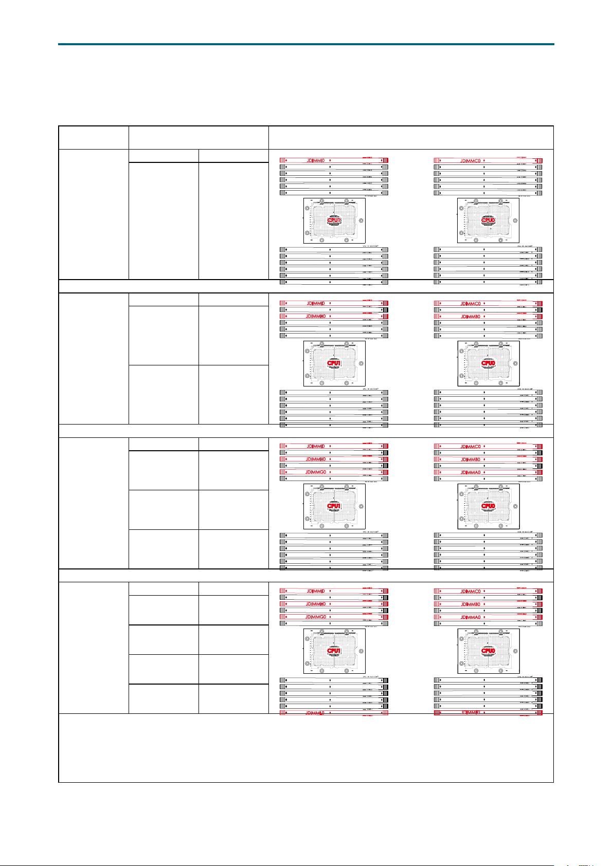
2�2�3 DIMM Slot Installation Order
Chapter 2. Hardware SetupLynx User Manual
DIMM
Numbers
2 DIMMs
4 DIMMs
DIMM Numbers Placement
CPU1 CPU0
JDIMMI1
JDIMMH0
JDIMMH1
JDIMMG0
JDIMMG1
JDIMMJ1
JDIMMJ0
JDIMMK1
JDIMMK0
JDIMML1
JDIMML0
JDIMMI1
JDIMMH1
JDIMMG0
JDIMMG1
JDIMMJ1
JDIMMJ0
JDIMMK1
JDIMMK0
JDIMML1
JDIMML0
CPU1CPU1
CPU1CPU1
JDIMM_I0 JDIMM_C0
CPU1 CPU0
JDIMM_I0 JDIMM_C0
JDIMM_H0 JDIMM_B0
JDIMMC1
JDIMMB0
JDIMMB1
JDIMMA0
JDIMMA1
JDIMMD1
JDIMMD0
JDIMME1
JDIMME0
JDIMMF1
JDIMMF0
JDIMMC1
JDIMMB1
JDIMMA0
JDIMMA1
JDIMMD1
JDIMMD0
JDIMME1
JDIMME0
JDIMMF1
JDIMMF0
CPU0CPU0
CPU0CPU0
6 DIMMs
8 DIMMs
CPU1 CPU0
JDIMM_I0 JDIMM_C0
JDIMM_H0 JDIMM_B0
JDIMM_G0 JDIMM_A0
CPU1 CPU0
JDIMM_I0 JDIMM_C0
JDIMM_H0 JDIMM_B0
JDIMM_G0 JDIMM_A0
JDIMM_L0 JDIMM_F0
JDIMMI1
JDIMMH1
JDIMMG1
JDIMMJ1
JDIMMJ0
JDIMMK1
JDIMMK0
JDIMML1
JDIMML0
JDIMMI1
JDIMMH1
JDIMMG1
JDIMMJ1
JDIMMJ0
JDIMMK1
JDIMMK0
JDIMML1
CPU1CPU1
JDIMMC1
JDIMMB1
JDIMMA1
JDIMMD1
JDIMMD0
JDIMME1
JDIMME0
JDIMMF1
JDIMMF0
JDIMMC1
JDIMMB1
JDIMMA1
JDIMMD1
JDIMMD0
JDIMME1
JDIMME0
JDIMMF1
CPU0CPU0
CPU0CPU0CPU1CPU1
11
Page 20
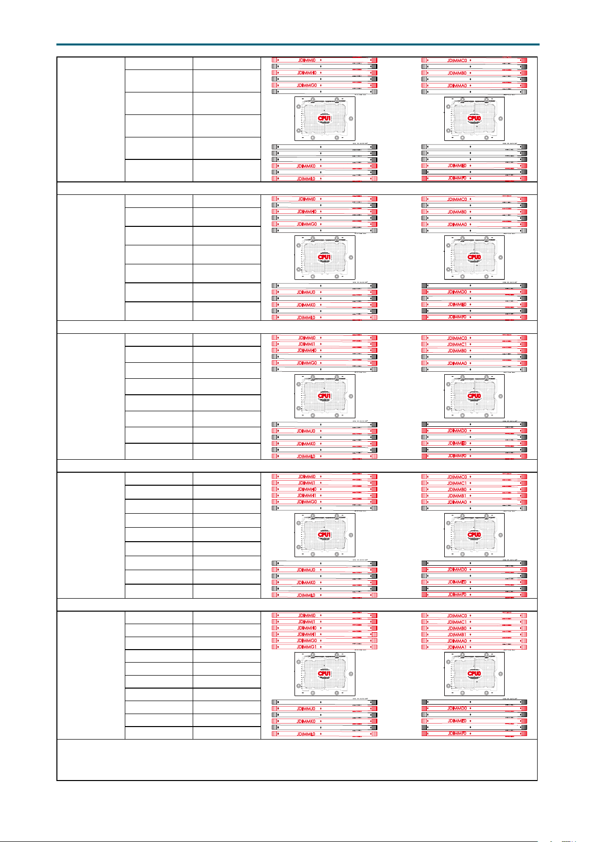
Chapter 2. Hardware SetupLynx User Manual
10 DIMMs
12 DIMMs
14 DIMMs
CPU1 CPU0
JDIMM_I0 JDIMM_C0
JDIMM_H0 JDIMM_B0
JDIMM_G0 JDIMM_A0
JDIMM_K0 JDIMM_E0
JDIMM_L0 JDIMM_F0
CPU1 CPU0
JDIMM_I0 JDIMM_C0
JDIMM_H0 JDIMM_B0
JDIMM_G0 JDIMM_A0
JDIMM_J0 JDIMM_D0
JDIMM_K0 JDIMM_E0
JDIMM_L0 JDIMM_F0
CPU1 CPU0
JDIMM_I0 JDIMM_C0
JDIMM_I1 JDIMM_C1
JDIMM_H0 JDIMM_B0
JDIMM_G0 JDIMM_A0
JDIMM_J0 JDIMM_D0
JDIMM_K0 JDIMM_E0
JDIMM_L0 JDIMM_F0
JDIMMI1
JDIMMH1
JDIMMG1
JDIMMJ1
JDIMMJ0
JDIMMK1
JDIMML1
JDIMMI1
JDIMMH1
JDIMMG1
JDIMMJ1
JDIMMK1
JDIMML1
JDIMMH1
JDIMMG1
JDIMMJ1
JDIMMK1
JDIMML1
CPU1CPU1
JDIMMC1
JDIMMB1
JDIMMA1
JDIMMD1
JDIMMD0
JDIMME1
JDIMMF1
JDIMMC1
JDIMMB1
JDIMMA1
JDIMMD1
JDIMME1
JDIMMF1
JDIMMB1
JDIMMA1
JDIMMD1
JDIMME1
JDIMMF1
CPU0CPU0
CPU0CPU0CPU1CPU1
CPU0CPU0CPU1CPU1
16 DIMMs
18 DIMMs
CPU1 CPU0
JDIMM_I0 JDIMM_C0
JDIMM_I1 JDIMM_C1
JDIMM_H0 JDIMM_B0
JDIMM_H1 JDIMM_B1
JDIMM_G0 JDIMM_A0
JDIMM_J0 JDIMM_D0
JDIMM_K0 JDIMM_E0
JDIMM_L0 JDIMM_F0
CPU1 CPU0
JDIMM_I0 JDIMM_C0
JDIMM_I1 JDIMM_C1
JDIMM_H0 JDIMM_B0
JDIMM_H1 JDIMM_B1
JDIMM_G0 JDIMM_A0
JDIMM_G1 JDIMM_A1
JDIMM_J0 JDIMM_D0
JDIMM_K0 JDIMM_E0
JDIMM_L0 JDIMM_F0
JDIMMG1
JDIMMJ1
JDIMMK1
JDIMML1
JDIMMJ1
JDIMMK1
JDIMML1
JDIMMA1
CPU0CPU0CPU1CPU1
JDIMMD1
JDIMME1
JDIMMF1
CPU0CPU0CPU1CPU1
JDIMMD1
JDIMME1
JDIMMF1
12
Page 21
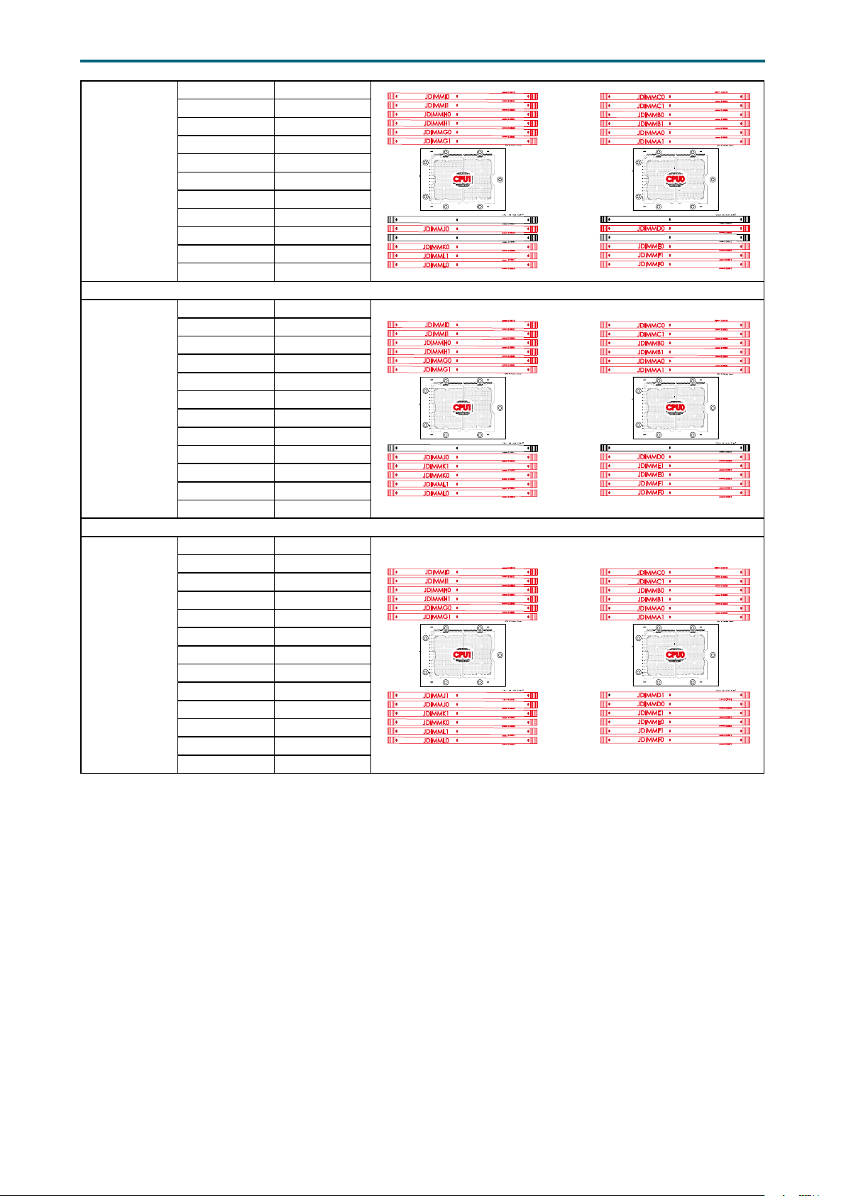
20 DIMMs
22 DIMMs
CPU1 CPU0
JDIMM_I0 JDIMM_C0
JDIMM_I1 JDIMM_C1
JDIMM_H0 JDIMM_B0
JDIMM_H1 JDIMM_B1
JDIMM_G0 JDIMM_A0
JDIMM_G1 JDIMM_A1
JDIMM_J0 JDIMM_D0
JDIMM_K0 JDIMM_E0
JDIMM_L1 JDIMM_F1
JDIMM_L0 JDIMM_F0
CPU1 CPU0
JDIMM_I0 JDIMM_C0
JDIMM_I1 JDIMM_C1
JDIMM_H0 JDIMM_B0
JDIMM_H1 JDIMM_B1
JDIMM_G0 JDIMM_A0
JDIMM_G1 JDIMM_A1
JDIMM_J0 JDIMM_D0
JDIMM_K1 JDIMM_E1
JDIMM_K0 JDIMM_E0
JDIMM_L1 JDIMM_F1
JDIMM_L0 JDIMM_F0
JDIMMJ1
JDIMMK1
JDIMMJ1
Chapter 2. Hardware SetupLynx User Manual
CPU0CPU0CPU1CPU1
JDIMMD1
JDIMME1
CPU0CPU0CPU1CPU1
JDIMMD1
24 DIMMs
CPU1 CPU0
JDIMM_I0 JDIMM_C0
JDIMM_I1 JDIMM_C1
JDIMM_H0 JDIMM_B0
JDIMM_H1 JDIMM_B1
JDIMM_G0 JDIMM_A0
JDIMM_G1 JDIMM_A1
JDIMM_J1 JDIMM_D1
JDIMM_J0 JDIMM_D0
JDIMM_K1 JDIMM_E1
JDIMM_K0 JDIMM_E0
JDIMM_L1 JDIMM_F1
JDIMM_L0 JDIMM_F0
CPU0CPU0CPU1CPU1
13
Page 22

Chapter 2. Hardware SetupLynx User Manual
Platform Environment Control Interface(PECI)
Pl
Chapter 3� Hardware Settings
This section provides illustrations that display the internal jumpers, connectors, and
system LED indicators.
3�1 Motherboard Block Diagram
USB2#9
USB3.0 Port #0~3
USB2.0 Port #0~3
@5Gb/s
SPI
MUX
SPI Flash
W25Q128V
Micro USB
(COM1)
USB2.0(X2)
(Internal Pin Header )
USB3.0(X2)
(Internal Box Header )
USB3.0(X2)
(Internal Box Header )
AST_USB Port #0~ 1 to PCH Port #4~5
USB2.0 Port #4~5
PCI Express x 1
PCI Express x 1
PCI Expr ess x 1
SPI Flash
W25Q64BVSSIG
Secure boot key
Flash
S25FL256SAGMFI001
PL-2303HXD
Box Header
(2x5 pin)
JCOM4
Box Header
(2x5 pin)
RJ45 x1
USB(X2)
Edge Connector
i210
i210
SPI
SPI2
ADM213
ADM213
P0 CH5/DIMM1/AA
P0 CH4/DIMM1/A6
P0 CH4/DIMM0/A4
P0 CH5/DIMM0/A8
COM1
COM2
P0 CH3/DIMM0/A0
P0 CH3/DIMM1/A2
10/100Mbps dedicate
management port
NCSI
CPU0
RTL8201EL
RJ45 x1
RJ45 x1
Aspe ed AST2500
PCH
P0 CH0/DIMM1/A2
RMII
P0 CH1/DIMM1/A6
P0 CH0/DIMM0/A0
COM4
COM5
NGFF M.2 2242/2280
P0 CH2/DIMM1/AA
P0 CH2/DIMM0/A8
P0 CH1/DIMM0/A4
DDR4 x16
EDY4016AABG-DR-F-D
VGA Pin Header
VGA CONN
LM9524 1CIMM
I2C4
LM9524 1CIMM-1
LM9524 1CIMM-2
LCM
Pin Header
(1x5 pin)
ADM213
BMC Debug
Pin Header
(1x3 pin)
Placement
CPU1
P1 CH3/DIMM0/A0
P1 CH4/DIMM0/A4
P1 CH3/DIMM1/A2
P1 CH5/DIMM0/A8
P1 CH4/DIMM1/A6
P1 CH5/DIMM1/AA
P1 CH0/DIMM1/A2
P1 CH1/DIMM1/A6
P1 CH2/DIMM1/AA
P1 CH0/DIMM0/A0
P1 CH1/DIMM0/A4
DIMM #I1
DIMM #I0
DIMM #H1
DIMM #H0
DIMM #G1
DIMM #G0
atform Environment Control Interface(PECI)
CPU1_VRD
VR13
PCI Express x 8
Port3c(IOU2)
PCI Express x 8
Port3aIOU2)
ECC DDR4 (1866/2133/2400/2667)
CPU1
Skylake-SP
(Cannonlake-SP)
LGA3647-0 Socket
CPU TDP 205W
Port1(IOU0 )
Port2(IOU1)
Steering
Resistors
PCI Express x 16
PCI Express x 16
Port2a(IOU1)
Port3a(IOU2)
PCIEX48 Riser Slot
CONN B
CONN A
Port3a(IOU2) Port2a(IOU1) Port1 a(IOU0)
PCIEX48 Riser Slot
CONN B
CONN C
CONN A
Port1a(IOU0)
PCI Express x 16
Port3a(IOU2)
PCI Express x 16
Port2a(IOU1)
PCI Express x 16
DIMM #L1
DIMM #L0
DIMM #K1
DIMM #K0
DIMM #J1
DIMM #J0
HFI0
HFI1
PCI Express x 8
Port3c(IOU2)
PCI Express x 8
Port3a(IOU2)
SATA#9
SATA#8
SATA#7
Lewisburg-4
PCH
TDP 19W
Debug port
SATAPort #11
@6Gb /s
MUX x1
MUX x1PCI Express x 2
USB2#8
USB3#5
USB3#4
USB3#3
USB3#2
USB3#1
USB3#0
NUVOTON
NPCT650
TPM 2.0
LPC/eSPI
NGFF M.2 2242/2280
PCIE x2 or SATA x1
PCI-E GEN3 @8GT/s X2 & SATA @6Gb/s
NGFF M.2 2242/2280
PCIE x2 or SATA x1
PCI-E GEN3 @8GT/s X2 & SATA @6Gb/s
DIMM #C1
DIMM #C0
DIMM #B1
DIMM #B0
DIMM #A1
DIMM #A0
HFI0
HFI1
CPU0_VRD
VR13
UPI0UPI1
ECC DDR4 (1866/2133/2400/2667)
CPU0
Skylake-SP
(Cannonlake-SP)
LGA3647-0 Socket
CPU TDP 205W
Port3(IOU2) Port2(IOU1)Port3(IOU2) Port1(IOU0)
Steering
Resistors
Omni-Path
Carrier
Card
UPI
UPI @10.4GT/s
UPI
UPI1UPI0
UPI @10.4GT/s
XDP
PCI Express x 16
Port1a(IOU0)
Steering
Resistors
DIMM #F1
DIMM #F0
DIMM #E1
DIMM #E0
DIMM #D1
DIMM #D0
DMI3 x 4
DMI GEN3@8GT/s
KRx4
Port1a(IOU0)
PCI Express x 16
PCI-E GEN3@8GT/s
SATA#1
SATA#0
PCI Express x 2
SATAPort #10
@6Gb/s
SATA#3
SATA#2
SATA#4
SATA#5
SATA#6
SATAPort #0~ 9
@6Gb/s
P1 CH2/DIMM0/A8
14
Page 23

Chapter 2. Hardware SetupLynx User Manual
Connector/Header/Jumper Location Connector/Header/Jumper Location
3�2 Motherboard Content List
1a1bPower Supply COM
Bus Disable Jumper
Power Supply PSKILL
2a
2b
Disable Jumper
3a
Backplane Power
3b
3c
Header
3d
Power Supply
4
Connector:
12V, 5VSB
PS_ON Enable
5
Jumper
Power Supply PMBus
6
Header
7 PMBUS Connector JPMBUS 27
8a
Fan 3B Connector
8b
Fan 3A Connector
8c
Fan 4 Connector
8d
Fan 1A Connector
8e
Fan 1B Connector
8f
FAN 2A Connector
8g
FAN 2B Connector
Power Supply
9a
9b
Connector: 12V
10a
PCH Fan Connector
10b
CPU0 Fan Connector
10c
CPU1 Fan Connector
11 DIMM Sockets
12a
External-1 Thermal
12b
Sensor
12c
13a
Front I/O USB Header
13b
Front I/O USB 2.0
14
Header
15 OCuLink Connector JSYS_EXT 35 BMC Reset Jumper JBMC_RST
16a
BMC GPIO Header
16b
17 Front Panel Header JFRNT_SSI 37
18 PCH SGPIO Header JSGPIO 38
19a
OCP Connector
19b
(PCIE)
J15, J16 21
J14, J17
JPWR1, JPWR2,
JPWR3, JPWR4
JPWR5 24 Buzzer Header JBUZZER
J18 25 LCM Header JLCM
JPMBUS_PDB 26 Intruder JINTRUDER
J19
J20
J23
J25
J26
J28
J27
JPWR6, JPWR7
J4
J21
J22
JEDEC Specified
DDR4 Connector
J8, J11, J24 32
JUSB_INT1,
JUSB_INT2
JUSB20 34 BMC Disable Jumper JBMC_DIS
JBMC_GPIO1,
JBMC_GPIO2
CN1, CN2 39 BMC I2C10 Header JBMC_I2C10
CPU0 Configurations
Jumper
22a
COM Port JCOM1, JCOM4
22b
BMC Debug Port
23
Header
OCP Connector (KR
Function)
28a
OCP Connector (PCIE) CN5, CN6
28b
29a
Riser Connector CN3, CN4
29b
30a
Riser Connector CN8, CN9
30b
31a
HFI Connector JHFI1, JHFI2
31b
BMC Debug Port Select
Jumper
33 IPMB Header JBMC_I2C1
36 Serial ATA
SATA6 Pin-7 Power
Header
SATA5 PIN-7 Power
Header
JPG_LOCK
JBMC_DP
CN7
J2
SATA1, SATA2,
SATA3, SATA4,
SATA5, SATA6,
SATA7, SATA8,
SATA9, SATA10
J12
J13
20 PCH SSGPIO Header JSSGPIO 40 PCH GPIO Header JPCH_GPIO
15
Page 24

Chapter 2. Hardware SetupLynx User Manual
Connector/Header/Jumper Location Connector/Header/Jumper Location
No Reboot (Watch
41
dog) Jumper
BIOS Recovery Mode
42
Jumper
43a
JNGFF Connector
43b
44
AUX Power Header
45 VGA Header JVGA_INT 55 Battery Socket JBAT
SATA-DOM Power
46
Connector: 5V
47 VRM SMB Header JSMB_VR 57 BIOS SPI ROM Socket JSPI_BIOS
Flash Descriptor
48
Security override
Jumper
J5 51 VROC Key Header JRAID_KEY
J7 52
JNGFF1,
JNGFF2
JPWR_AUX 54 ESPI Port JESPI
JDOM_PWR 56 Debug Port JLPC_DP
J3 58 PCIE Hot-Plug SMB JPCIE_HP
ME Force Recovery
Mode Jumper
53 Speaker JSPKR
J6
NTB Configuration
49
Jumper
50 Clear CMOS Jumper JCMOS
JNTB
59a
Power Supply
Connector
59b
J9, J10
16
Page 25
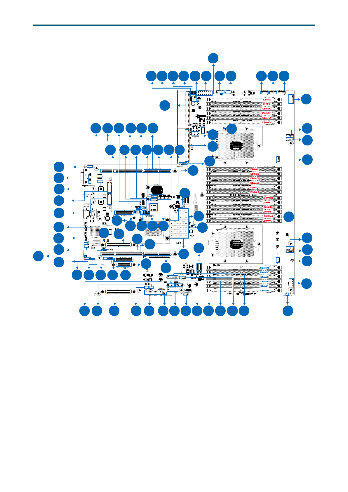
3�3 Motherboard Layout
1b
2a 2b
59b
1a
3d
Chapter 2. Hardware SetupLynx User Manual
5
7
6
4
8c 8b 8a
9a
32
22b
45
44
43b
43a
39
16a
33
22a
48
47
34
24
23
25
26
28b
19b
51
27
52
29b 30b
53
54 55 56 57
35
40 10a
35a
28a
29a
41
42
30a
SATA4 SATA10
SATA3 SATA9
SATA2 SATA8
SATA1 SATA7
46
SATA6
SATA5
36
58
38
31a
37
59a
12b
3c
31b
b
CPU1
CPU0
JDIMMJ1
JDIMMJ0
JDIMMK0
JDIMML1
JDIMML0
JDIMMC0
JDIMMC1
JDIMMB0
JDIMMB1
JDIMMA0
JDIMMA1
11
24 DIMM Sockets
JDIMMD1
JDIMMD0
JDIMME1
JDIMME0
JDIMMF1
JDIMMF0
50
49
8g
8f
10c
8e
8d
10b
9b
21
20
18
17
12a
13a
17
16b
15
3b
14
3a19a
13b
12c
Page 26
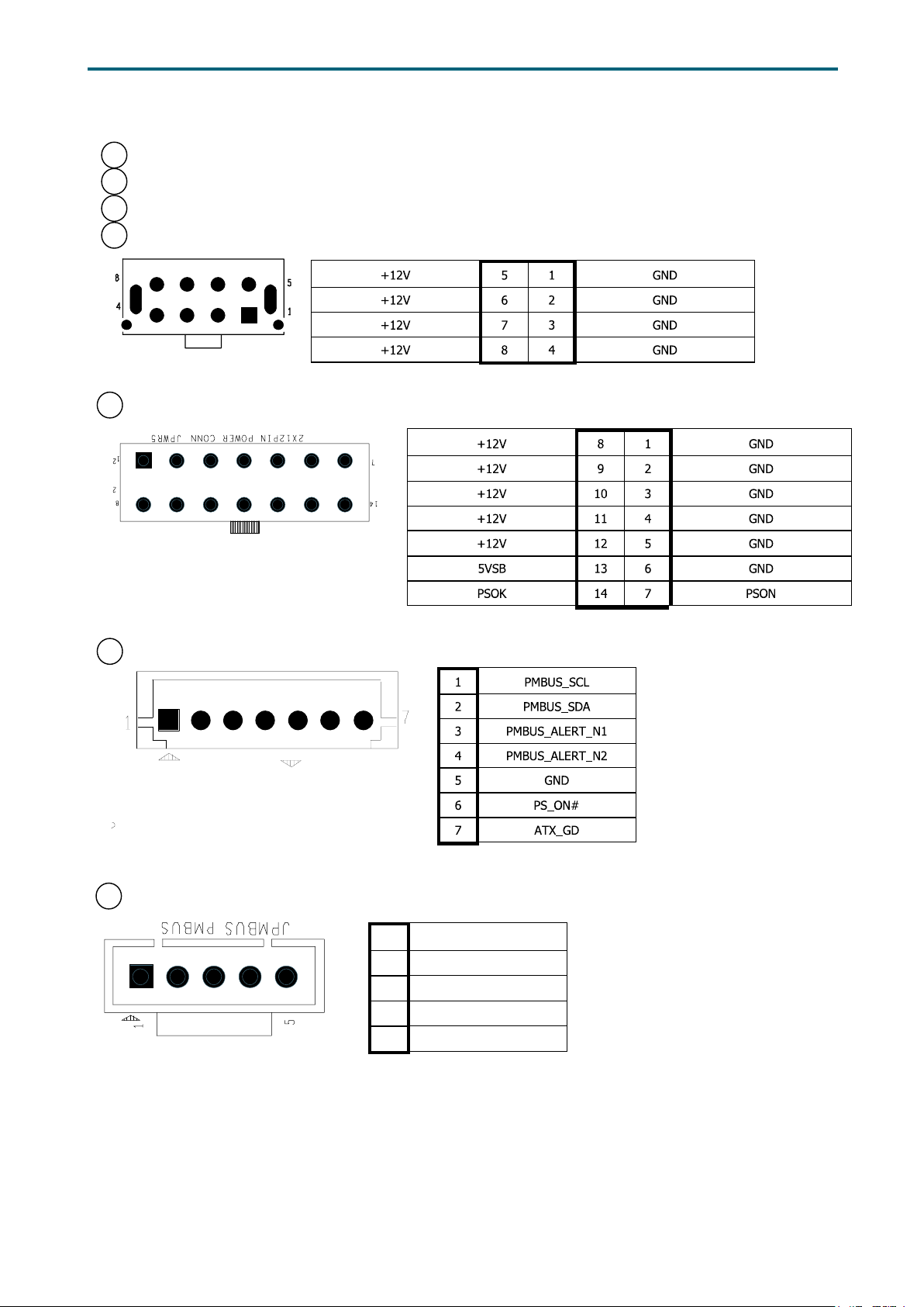
3�4 Connector and Jumper
3a Backplane Power Header (JPWR1)
3b Backplane Power Header (JPWR2)
3c Backplane Power Header (JPWR3)
3d Backplane Power Header (JPWR4)
4 Power Supply Connector (JPWR5)
Chapter 2. Hardware SetupLynx User Manual
6 Power Supply Header (JPMBUS_PDB)
7 PMBus Header (JPMBUS)
1 SMB_PMBUS_CLK
2 SMB_PMBUS_DATA
3 PMBUS_ALERT_N
4 GND
5 +3.3V
18
Page 27
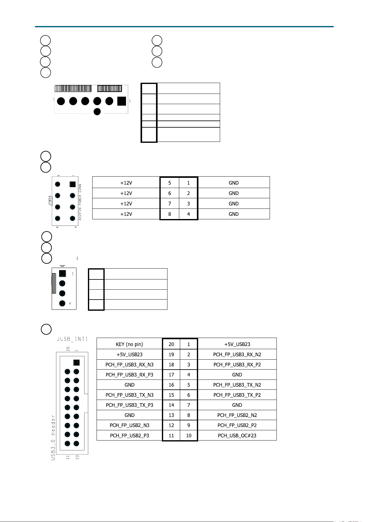
8a Fan Connector (J19) 8e Fan Connector (J26)
8b Fan Connector (J20) 8f Fan Connector (J27)
8c Fan Connector (J23) 8g Fan Connector (J28)
8d Fan Connector (J25)
1 GND
2 +12V
3 TACH
4 PWM
5 FAN_PRSNT_N
6 LED_FAN_FAULT
9a Power Supply Connector: 12V (JPWR6)
9b Power Supply Connector: 12V (JPWR7)
Chapter 2. Hardware SetupLynx User Manual
10a
PCH Fan Connector (J4)
10b
CPU Fan Connector (J21)
10C
CPU Fan Connector (J22)
1 GND
2 +12V
3 TACH
4 PWM
13 Front I/O USB Header (JUSB_INT1/JUSB_INT2)
19
Page 28
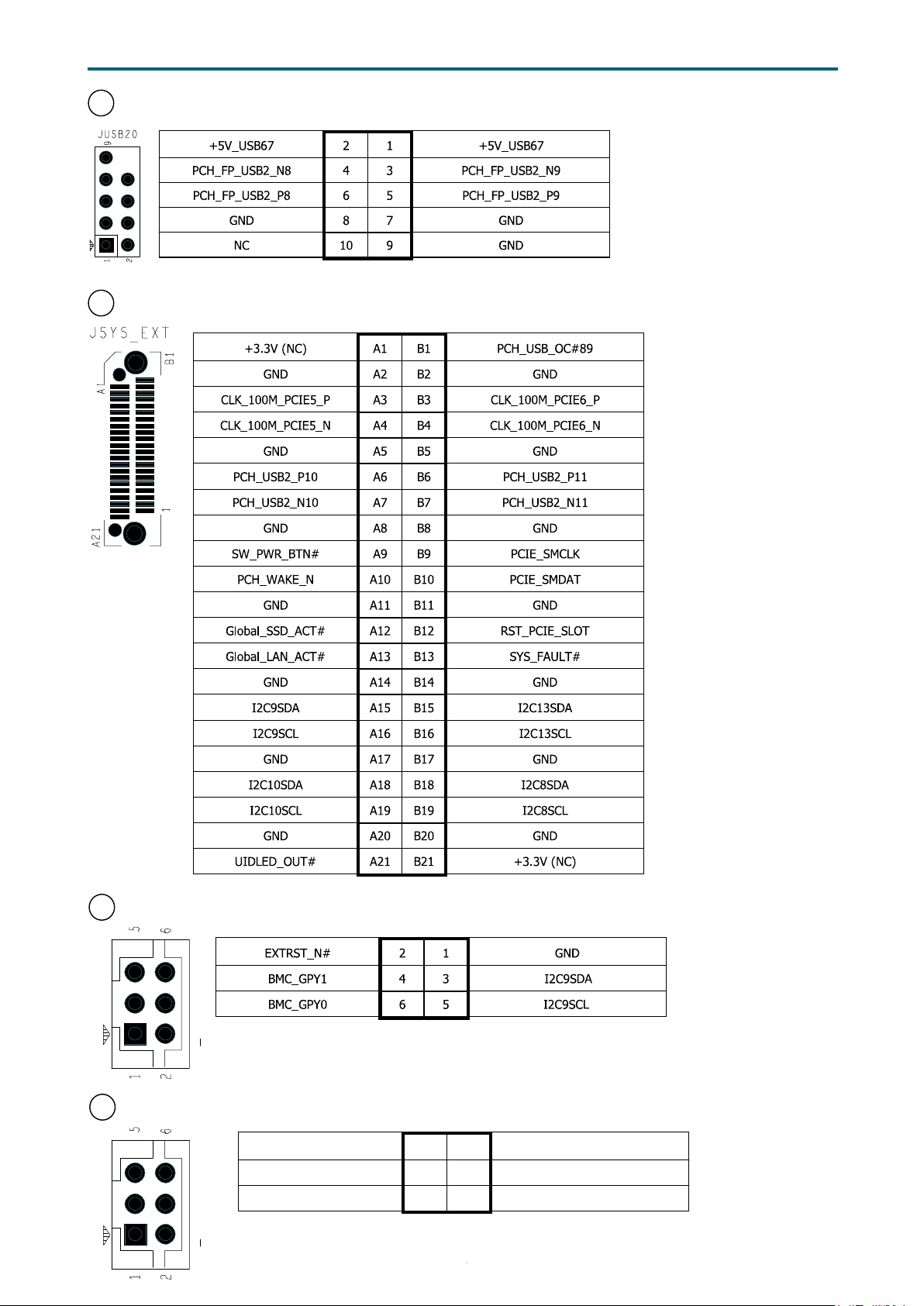
14 Front I/O USB 2.0 Header (JUSB20)
15 OCulink Connector (JSYS_EXT)
Chapter 2. Hardware SetupLynx User Manual
16a
BMC GPIO Header (JBMC_GPIO1)
16b
BMC GPIO Header (JBMC_GPIO2)
GPIOP3 2 1 GND
GPIOP2 4 3 GPIOI3
GPION7 6 5 +3.3V_DUAL
20
Page 29
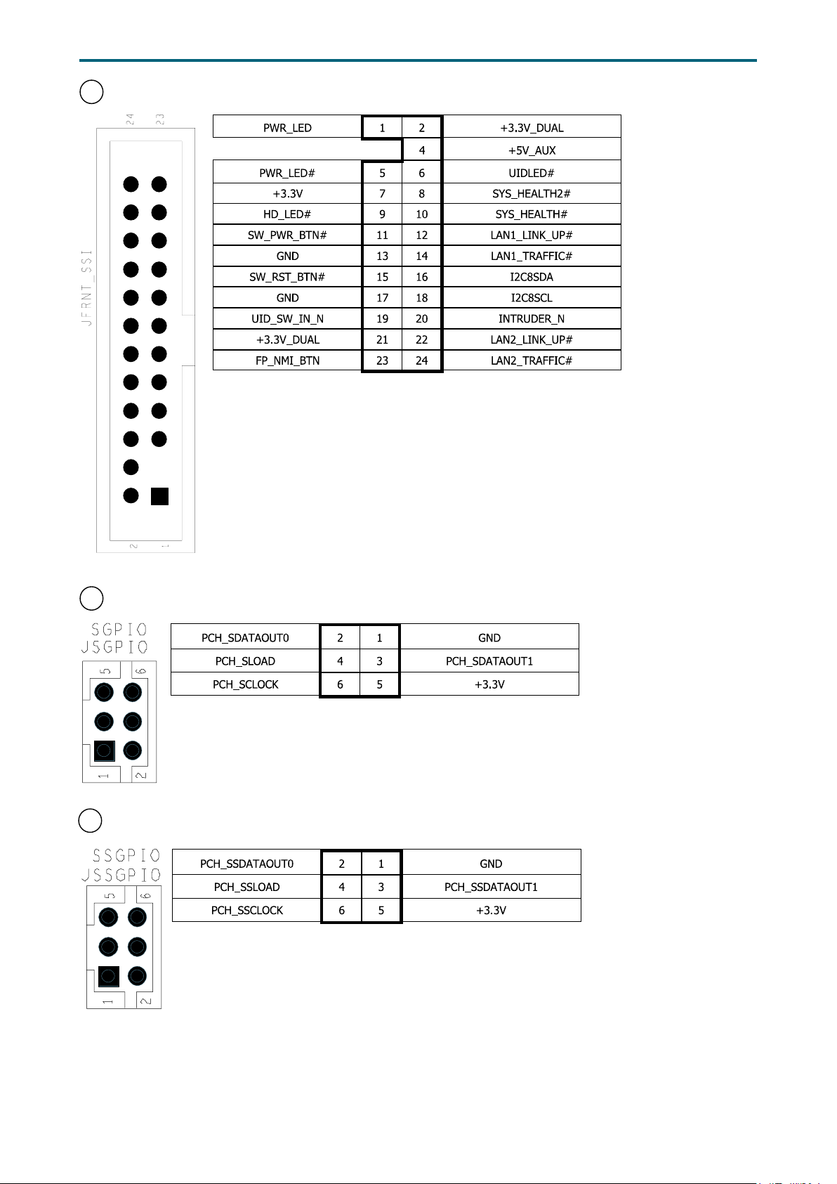
Chapter 2. Hardware SetupLynx User Manual
17 Front Panel Header (
JFRNT_SSI
)
PCH SGPIO Header (JSGPIO)
18
20 PCH SSGPIO (JSSGPIO)
21
Page 30
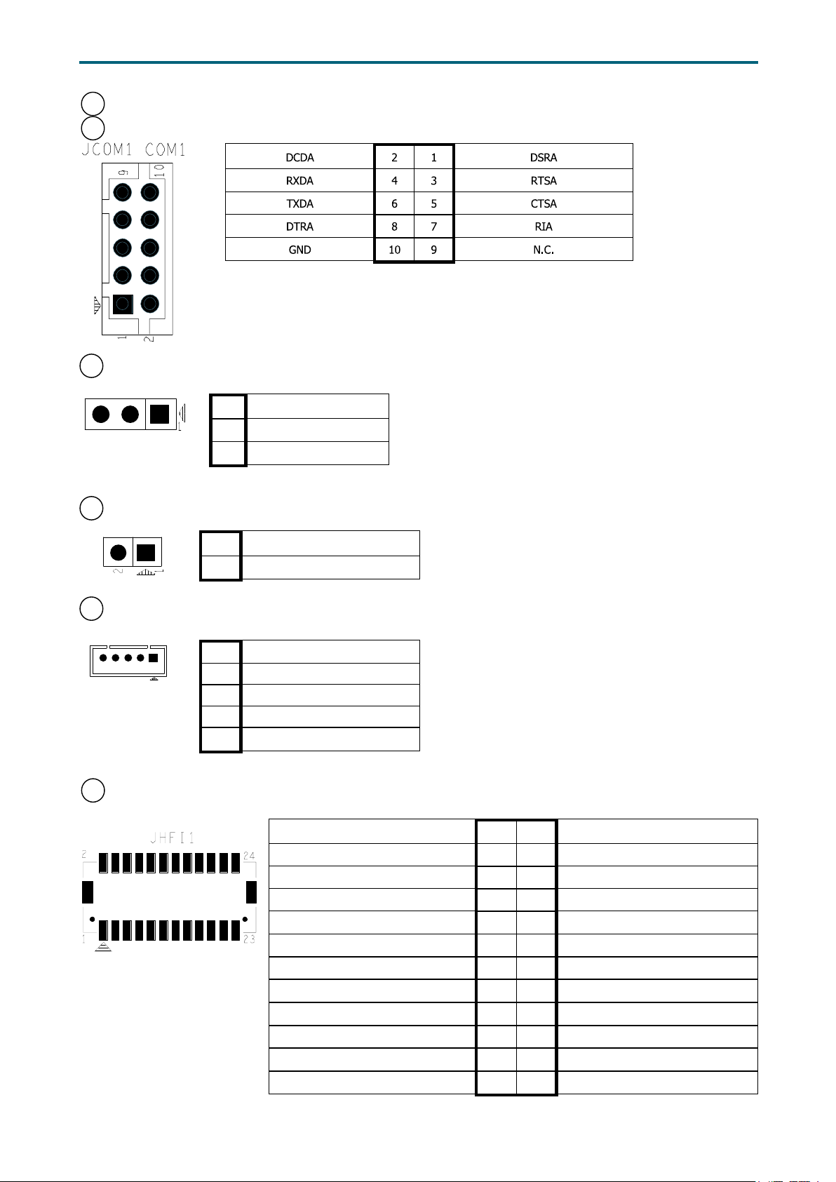
22a
COM Port (JCOM1)
22b
COM Port (JCOM4)
23 BMC Debug Port Header (JBMC_DP)
1 BMC_UART_TXD5
2 BMC_UART_RXD5
3 GND
Chapter 2. Hardware SetupLynx User Manual
24 Buzzer Header (JBUZZER)
1 +5V
2 BMC_BUZZER-
25 LCM Header (JLCM)
1 SW_PWR_BTN#
2 SW_RST_BTN#
3 TXDC
4 RXDC
5 GND
31a
HFI Header (JHFI1/JHFI2)
FM_MODPRST_HFI0_CPU0_LVT2_N 3 4 SMB_HFI0CPU0_LVC2_SDA
FM_MODPRST_HFI1_CPU0_LVT2_N 11 12 SMB_HFI1CPU0_LVC2_SDA
GND 1 2 SMB_HFI0CPU0_LVC2_SCL
LED_HFI0_CPU0_N 5 6 RST_HFI0_CPU0_LVT2_N
GND 7 8 IRQ_HFI0_CPU0_LVT2_N
GND 9 10 SMB_HFI1CPU0_LVC2_SCL
LED_HFI1_CPU0_N 13 14 RST_HFI1_CPU0_LVT2_N
GND 15 16 IRQ_HFI1_CPU0_LVT2_N
+12V 17 18 +3.3V
PVPP_ABC_GD 19 20 +3.3V
PVPP_ABC 21 22 SMB_3V3SB_CLK
GND 23 24 SMB_3V3SB_DAT
22
Page 31
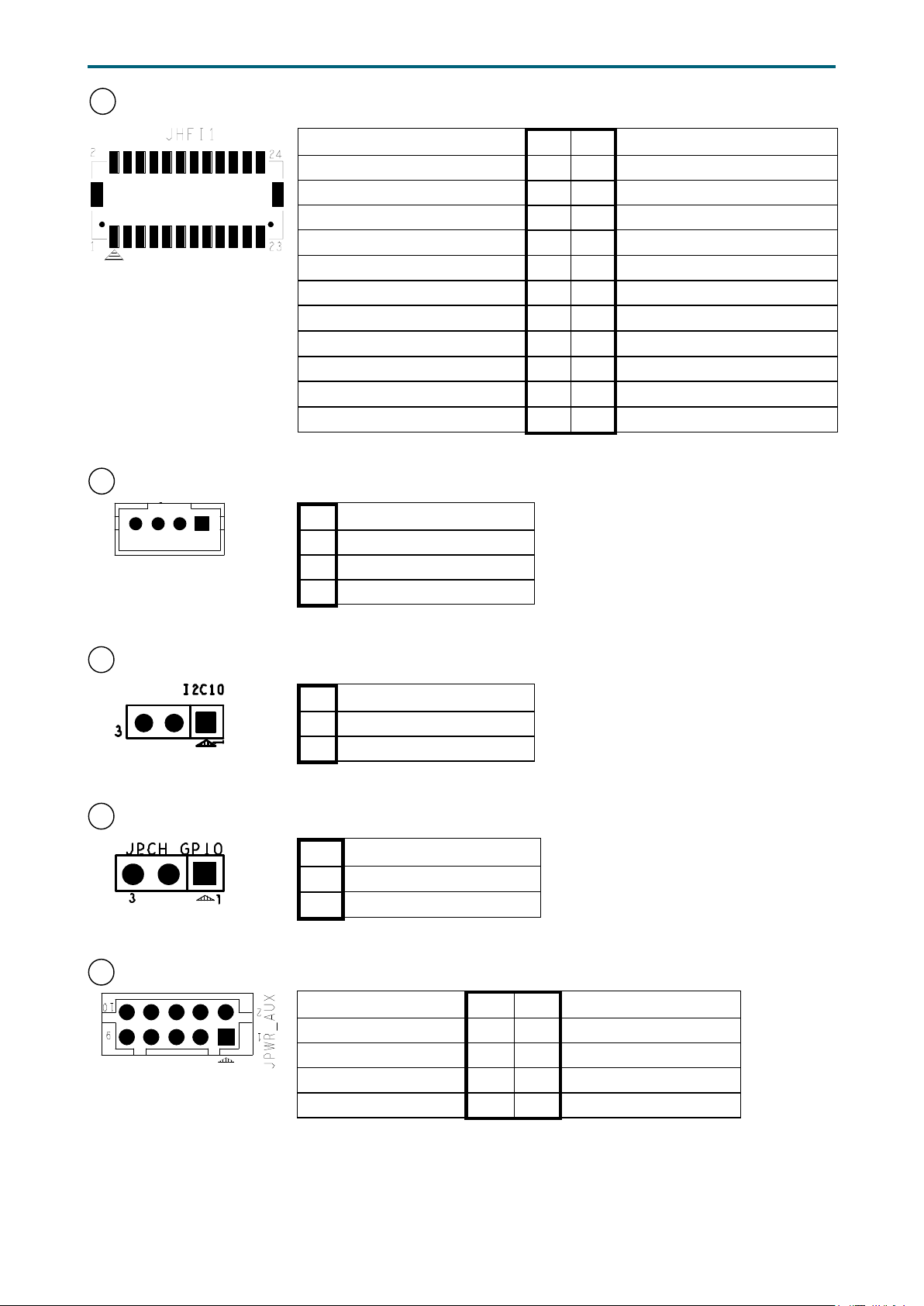
31b
HFI Header (JHFI2)
FM_MODPRST_HFI0_CPU1_LVT2_N 3 4 SMB_HFI0CPU1_LVC2_SDA
FM_MODPRST_HFI1_CPU1_LVT2_N 11 12 SMB_HFI1CPU1_LVC2_SDA
33 IPMB Header (JBMC_I2C1)
Chapter 2. Hardware SetupLynx User Manual
GND 1 2 SMB_HFI0CPU1_LVC2_SCL
LED_HFI0_CPU1_N 5 6 RST_HFI0_CPU1_LVT2_N
GND 7 8 IRQ_HFI0_CPU1_LVT2_N
GND 9 10 SMB_HFI1CPU1_LVC2_SCL
LED_HFI1_CPU1_N 13 14 RST_HFI1_CPU1_LVT2_N
GND 15 16 IRQ_HFI1_CPU1_LVT2_N
+12V 17 18 +3.3V
PVPP_GHI_GD 19 20 +3.3V
PVPP_GHI 21 22 SMB_3V3SB_CLK
GND 23 24 SMB_3V3SB_DAT
1 I2C1SDA
2 GND
3 I2C1SCL
4 N.C.
39 BMC I2C10 Header (JBMC_I2C10)
1 I2C10SCL
2 I2C10SDA
3 GND
40 PCH GPIO Header (JPCH_GPIO)
1 PCH_GPP_C16
2 PCH_GPP_C17
3 GND
44 AUX Power Header (JPWR_AUX)
+12V 2 1 +12V
+3.3V 4 3 +3.3V
+3.3V_DUAL 6 5 +3.3V_DUAL
GND 8 7 GND
GND 10 9 GND
23
Page 32
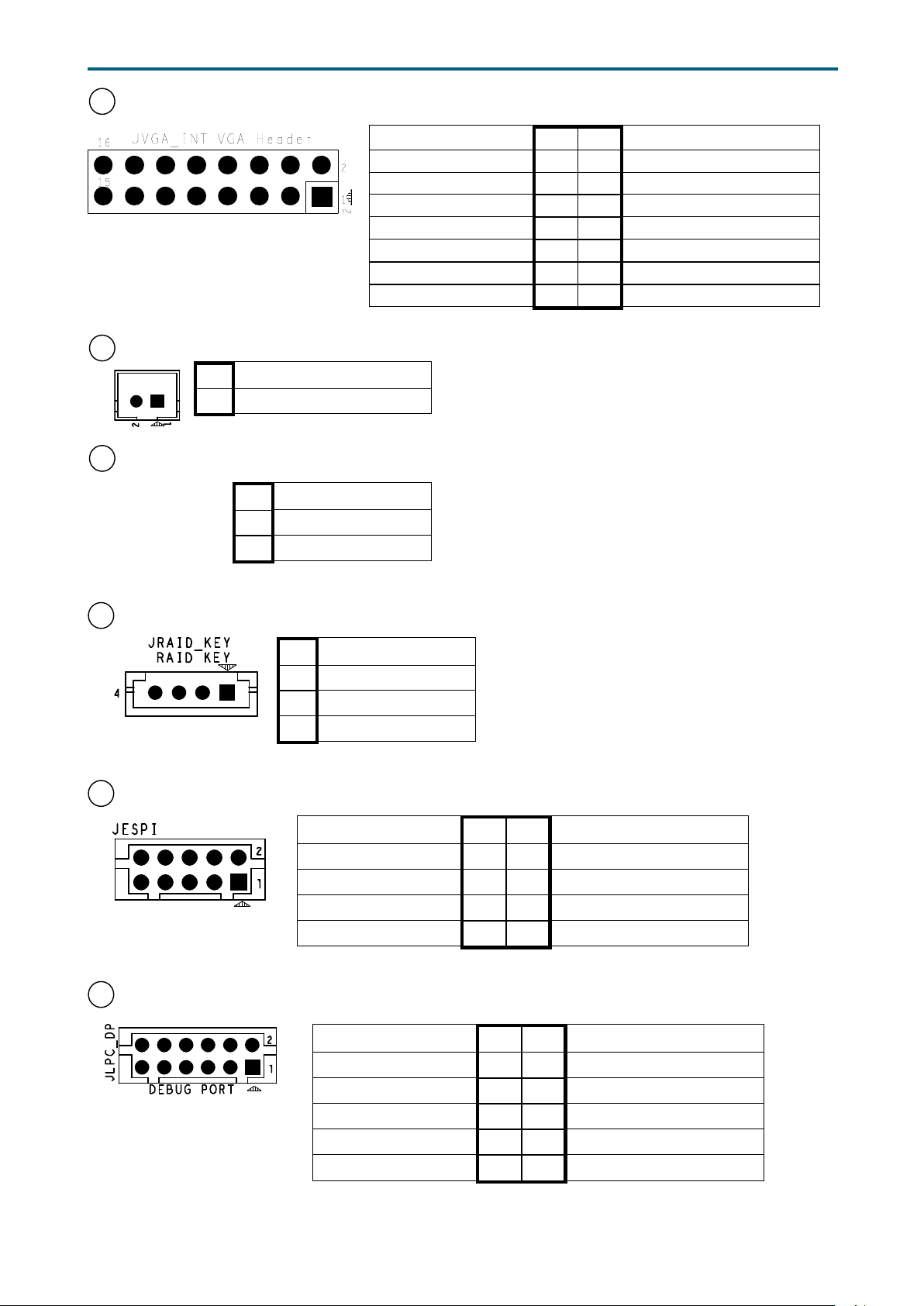
45 VGA Header (JVGA_INT)
1
DACROA 2 1 GND
DACBOA 8 7 GND
AHSYNCO 10 9 N.C.
DVO_5V 12 11 AVSYNCO
DDC_CLKO 16 15 GND
46 SATA DOM Power Header (JDOM_PWR)
1 +12V
2 GND
47 VRM SMB Header (JSMB_VR)
1 SMB_VR_DAT
2 GND
3 SMB_VR_CLK
Chapter 2. Hardware SetupLynx User Manual
N.C. 4 3 DACGOA
GND 6 5 DDC_DATAO
GND 14 13 GND
51 VROC KEY BOX Header (JRAID_KEY)
1 GND
2 +3.3V_DUAL
3 GND
4 PCH_GPP_C10
54 Debug Port Header (JESPI)
PGPPA_PCH 2 1 +5V_AUX
10
9
SMB_HOST_3V3_DAT 4 3 PCH_SMI_N
SMB_HOST_3V3_CLK 6 5 PCH_LPC_CLKRUN_N
PCH_ESPI_RST_N 8 7 PCH_PME_N
PCH_ESPI_ALENT1_N 10 9 GND
56 Debug port header (JLPC_DP)
10
9
CLK_24M_DP80 2 1 GND
PCH_LFRAME_N 4 3 PCH_LDRQ0_N
RST_PLTRST_N 6 5 AST_SERIRQ
PCH_LPC_LAD3 8 7 PCH_LPC_LAD2
+3.3V 10 9 PCH_LPC_LAD1
PCH_LPC_LAD0 12 11 GND
24
Page 33
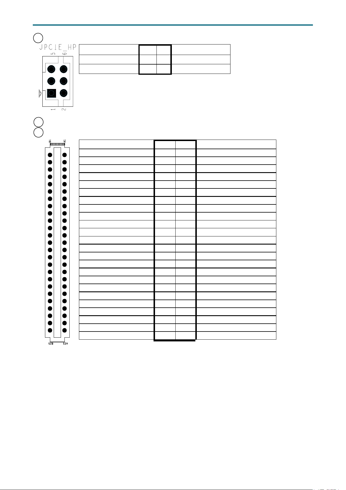
58 PCIE Hot-Plug SMB Header (JPCIE_HP)
CPU1_HP_I2C_CLK 2 1 CPU0_HP_I2C_CLK
CPU1_HP_I2C_DAT 4 3 CPU10_HP_I2C_DAT
GND 6 5 +3.3V
59a
Power Supply Connector (J9)
59b
Power Supply Connector (J10)
GND A1 B1 GND
GND A2 B2 GND
GND A3 B3 GND
GND A4 B4 GND
GND A5 B5 GND
GND A6 B6 GND
GND A7 B7 GND
GND A8 B8 GND
GND A9 B9 GND
+12V A10 B10
+12V A11 B11
+12V A12 B12
+12V A13 B13
+12V A14 B14
+12V A15 B15
+12V A16 B16
+12V A17 B17
+12V A18 B18
PMBUS_SDA A19
PMBUS_SCL A20
PS_ON A21
ALERT A22
SENSE- A23
SENSE+ A24
PW_OK A25
B19
B20
B21
B22
B23
B24
B25
Chapter 2. Hardware SetupLynx User Manual
+12V
+12V
+12V
+12V
+12V
+12V
+12V
+12V
+12V
PMBUS_A0
PMBUS_A1
+12V_AUX
CR_BUS_N
12LS
PSKILL
COM_BUS
25
Page 34
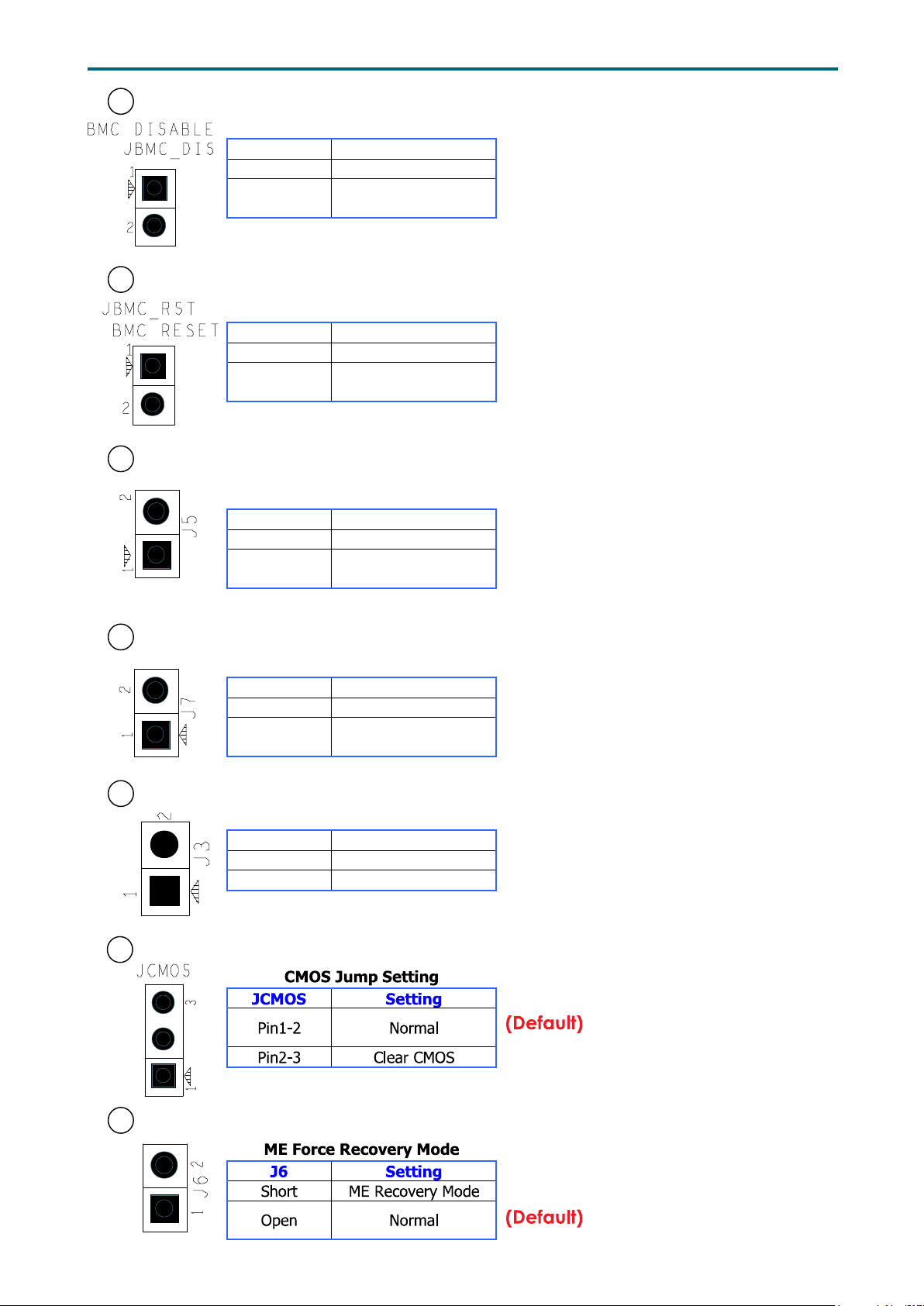
34 BMC Disable Jumper (JBMC_DIS)
BMC Disable Jump Setting
t)
BMC Reset Jump Setting
t)
No Reboot(Watch Dog)
t)
BIOS Recovery Mode
t)
t)
Chapter 2. Hardware SetupLynx User Manual
JBMC_DIS
Short Disable
Open Normal
Setting
35 BMC Reset Jumper (JBMC_RST)
JBMC_RST
Short Reset BMC
Open Normal
Setting
41 No Reboot (Watch dog) Jumper (J5)
J5 Setting
Short Enable
Open Disable
(Defaul
(Defaul
(Defaul
42 BIOS Recovery Mode Jumper (J7)
J7 Setting
Short BIOS Recovery Mode
Open Normal
(Defaul
48 Flash Descriptor Security override Jumper (J3)
J3 Setting
Short Flash Security override
Open Normal (Defaul
50 CMOS Jumper (JCMOS)
52 ME Force Recovery Mode Jumper (J6)
26
Page 35
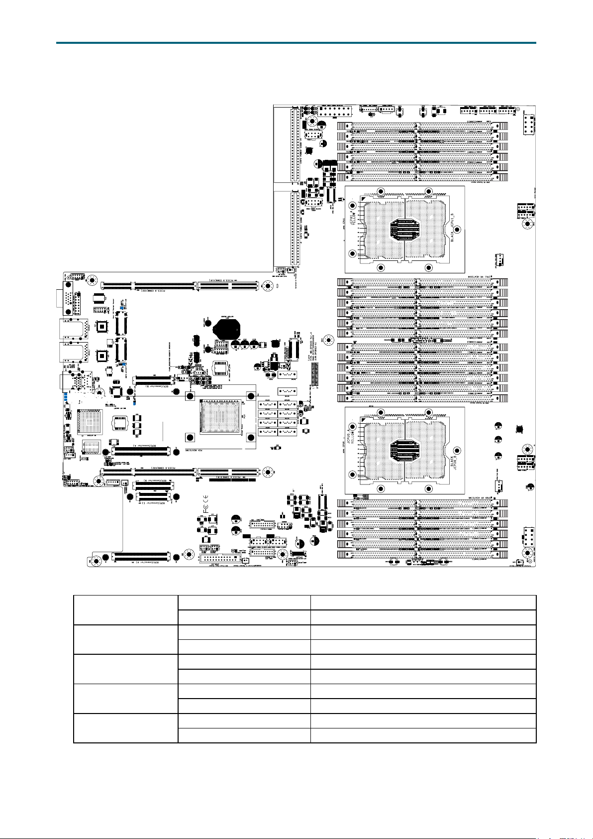
3�5 System LED Indicator
3�5�1 Internal LED
NGFF2 ACT LED
Chapter 2. Hardware SetupLynx User Manual
JDIMMJ0
JDIMMK1
NGFF1 ACT LED
UID LED
UID LED
RSMRST PG LED
RSMRST PG LED
SYSTEM PG LED
SYSTEM PG LED
BMC Heart Beat
SYSPG LED
RSMRST PGLED
UID LED
NGFF LED
JDIMML0
JDIMMC0
JDIMMC1
JDIMMB0
JDIMMB1
JDIMMA1
BMC Heart Beat LED
JDIMMD1
JDIMMD0
JDIMME1
Green (Blinking) BMC activity is detected.
OFF BMC is not active.
Green System power is on.
OFF System power is off.
Yellow Resume Well Reset is on.
OFF Resume Well Reset is off.
Blue UID activity is detected.
Off UID activity is not detected.
Blue (Blinking) NGFF activity is detected.
Off NGFF activity is not detected.
27
Page 36
Chapter 4. BIOS Conguration SettingsLynx User Manual
Chapter 4. BIOS Conguration Settings
This chapter demonstrates how to configure the UEFI BIOS settings in your
system device. You can enter the BIOS screen during system startup.
To enter BIOS conguration settings,
• Press ESC during the Power-On-Self-Test (POST)
To enter BIOS after POST, you have to restart the system by using one of the
three methods:
• Press Ctrl + Alt + Delete.
• Press the reset button on the system chassis.
• Turn the system off and on.
NOTE
The following pages provide the details of BIOS menu. Please notice that the BIOS
menu are continually changing due to the BIOS update.
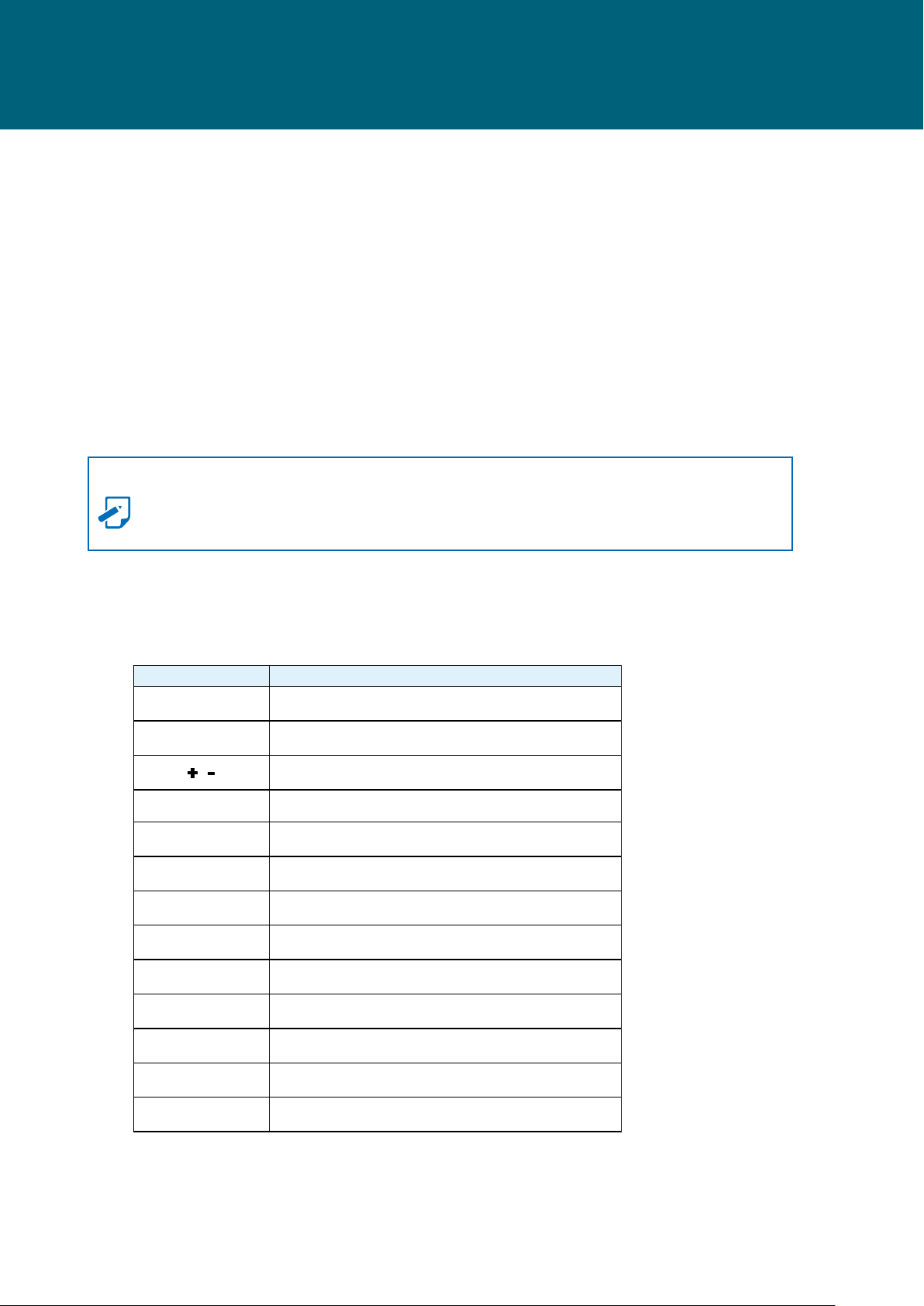
4�1 Navigation Keys
The navigation keys are listed below.
Function Key Description
, , ,
Enter Select and enter sub-screen.
+ , - Modify selected option.
F5, F6 Change values.
F10 Save changes and exit.
F1 General help.
F2 Previous Value.
F3 Optimized defaults.
F4 Save & Exit.
F7 Discard Change and Exit.
F9 Load Optimal Default for all values.
Select item.
F12 Print Screen.
Esc
Exit the current menu screen.
28
Page 37
4�2 BIOS Menu
Press and to select the options of the menu bar.
Press Enter to access the option screen.
Menu Description
Displays system information such as CPU bus
Main
Advanced
Security Sets passwords and security functions.
Boot Sets boot options such as Quick Boot or USB Boot.
speed, system memory speed, total installed
memory, current EFI language, and system date &
time.
Allows conguration of advanced system
settings such as ACPI features, boot, and chipset
conguration.
Chapter 4. BIOS Conguration SettingsLynx User Manual
Power
Exit
Allows conguration of timer, System Event Log,
and BMC network.
Allows user to save or discard BIOS changes, and
load optimal or custom default settings.
4�2�2 Startup
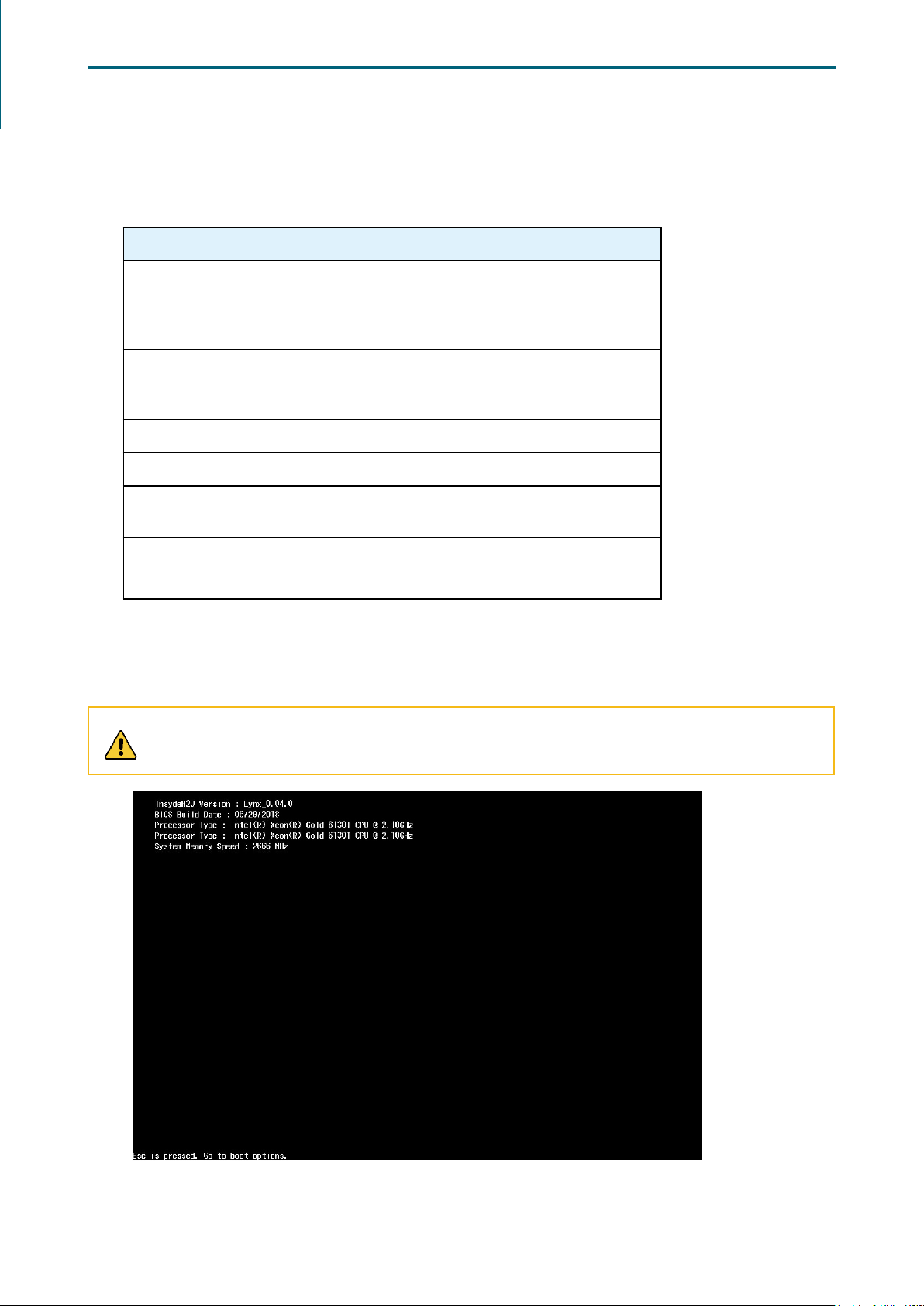
Step 1 Press ESC to run the BIOS setup procedure.
CAUTION
When Quiet Boot is enables, OEM logo will be displayed instead of post messages.
29
Page 38
Chapter 4. BIOS Conguration SettingsLynx User Manual
Step 2 There will be a message “Entering SETUP” displayed on the diagnostics
screen.
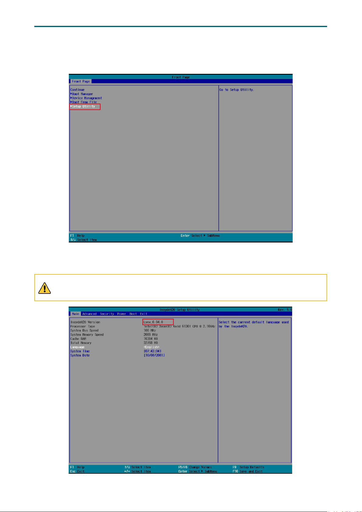
Step 3 Identify the BIOS version.
CAUTION
For the official released version, the last digit of the BIOS version must end in a “0.“
30
Page 39
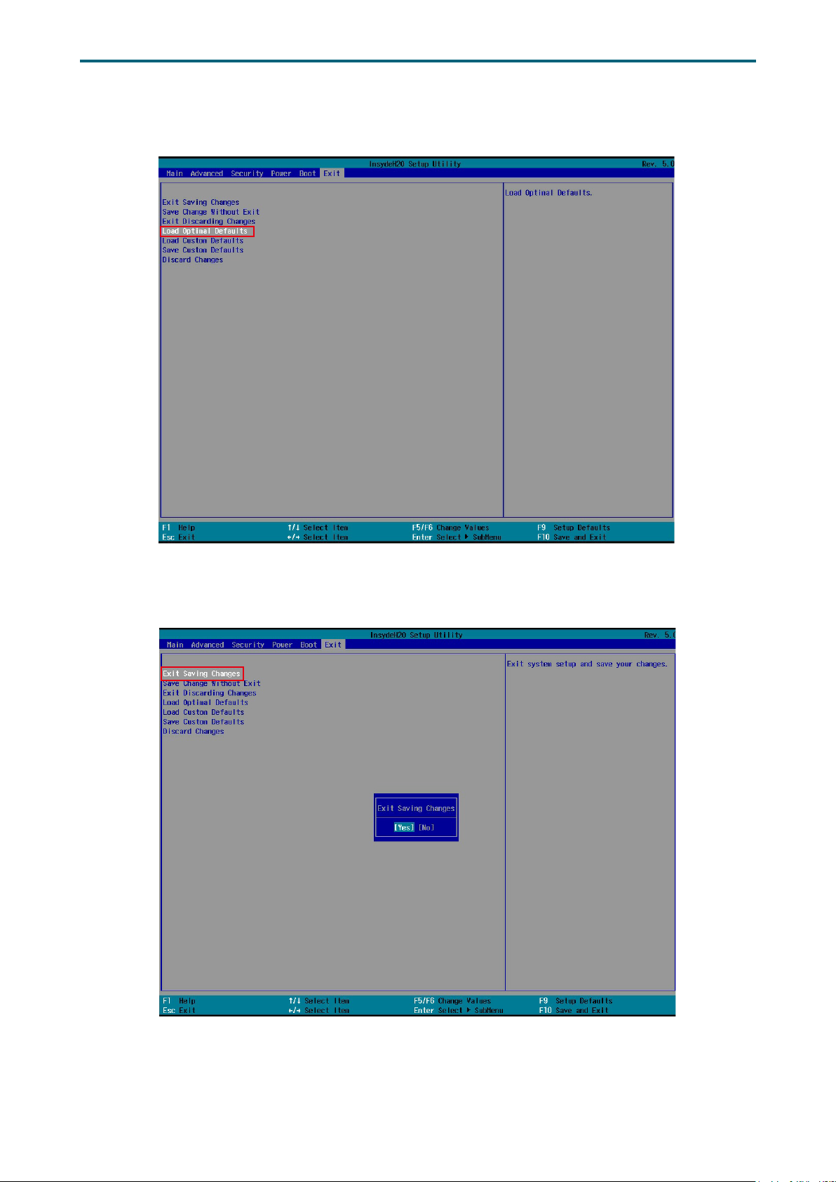
Step 4 Load Optimal Default Setting.
Chapter 4. BIOS Conguration SettingsLynx User Manual
Step 5 Save the setting and exit the BIOS setup utility.
31
Page 40
Chapter 4. BIOS Conguration SettingsLynx User Manual
4�2�3 Update
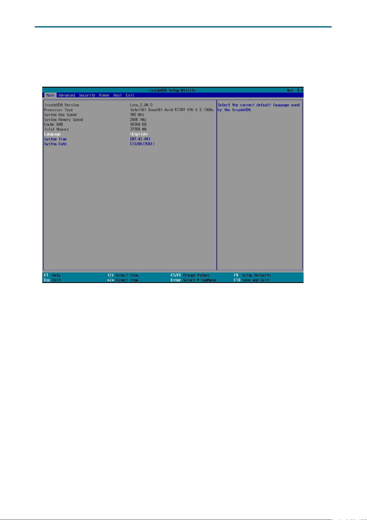
To identify the latest BIOS version, please check the BIOS setup.
32
Page 41
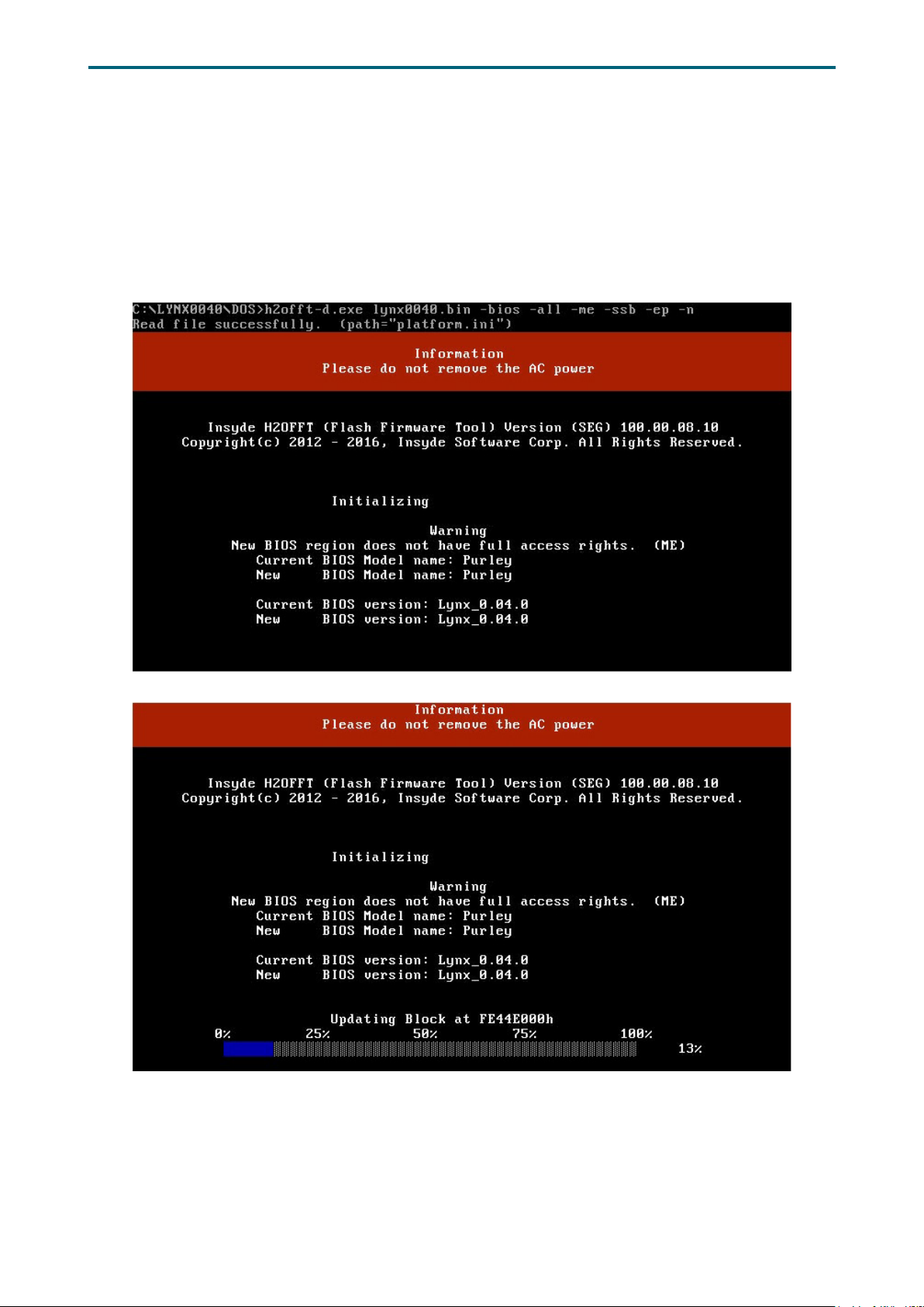
Chapter 4. BIOS Conguration SettingsLynx User Manual
Update BIOS by INSYDE H2OFFT-D utility under DOS environment
If you need to update Flash in the DOS environment, please use H2OFFT-D utility. To use
this utility, you must include the flash.bat , H2OFFT-D.exe, and bin file in the same folder.
Please follow the instructions to update flash:
Step 1 Execute flash.bat to update Flash in the DOS environment.
Step 2 Reboot the system.
33
Page 42
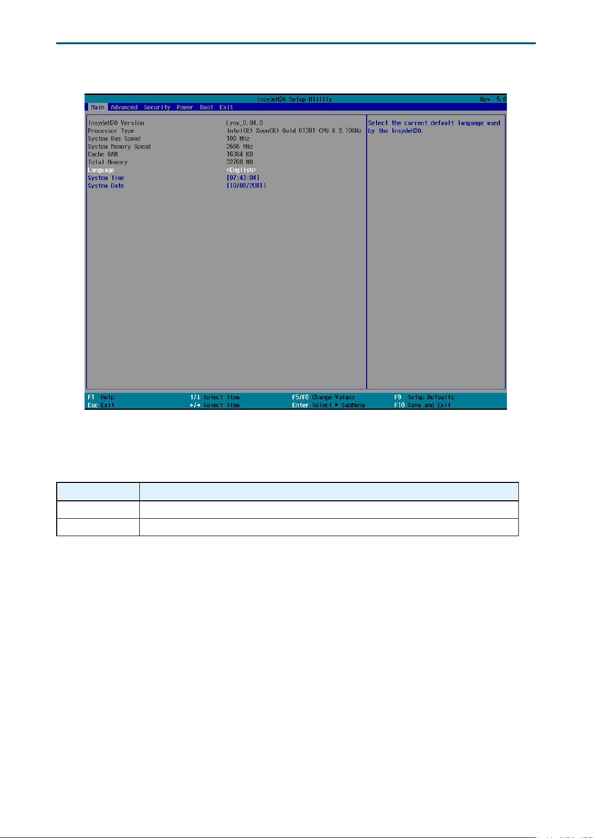
4�3 Main
Chapter 4. BIOS Conguration SettingsLynx User Manual
Main Option Key:
4�3�1 Main
Option Key Description
System time Configures the current time.
System date Configures the current date.
34
Page 43
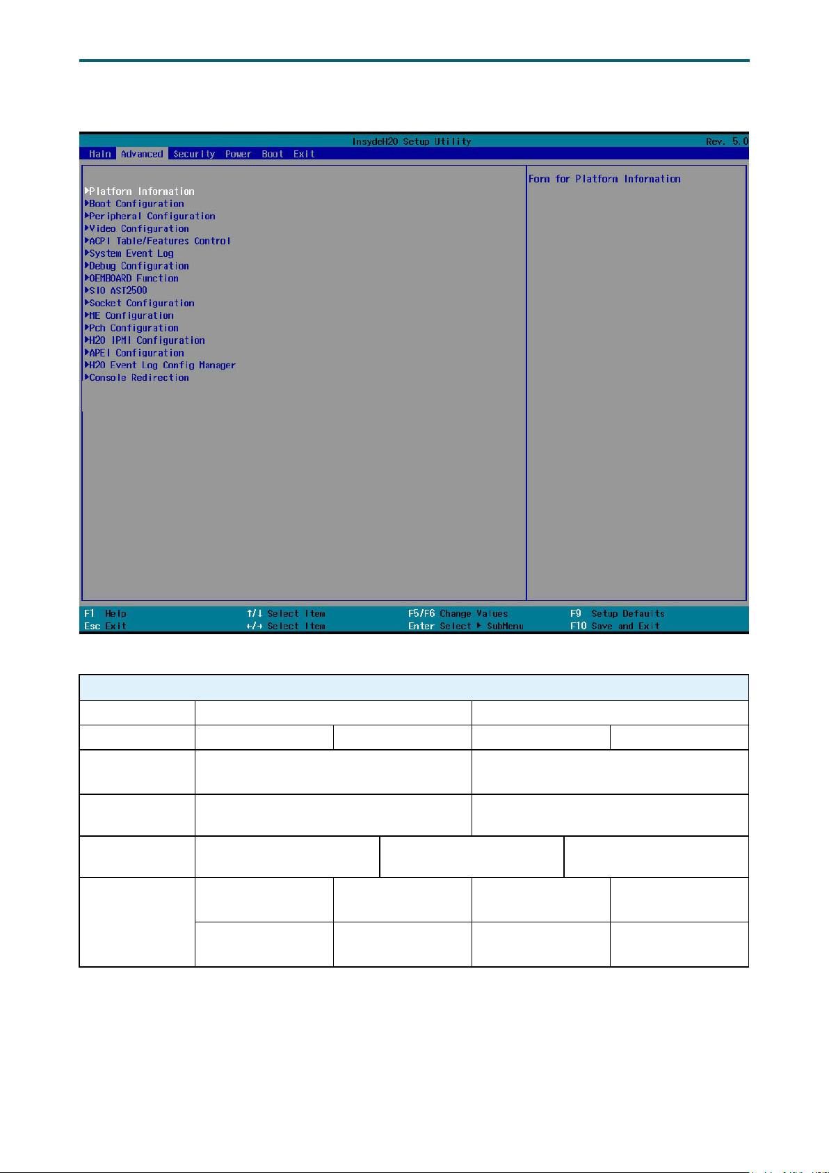
4�4 Advanced
Chapter 4. BIOS Conguration SettingsLynx User Manual
Advanced Option Key:
4.4.1 Boot Conguration
Boot Configuration
Numlock On Off
SCU Resolution 640*480 800*600 1024*768 Auto
CSM on
Demand
USB BIOS
Support
USB BIOS
Support
BIOS Guard
Enable Disable
On Off
Enable Disable UEFI Only
Enable ASAP Enable Proper Enable ALAP
Enable Proper
avoid wear-out
Enable ALAP avoid
wear-out
Unsupport Disable
Enable ASAP
avoid wear-out
35
Page 44
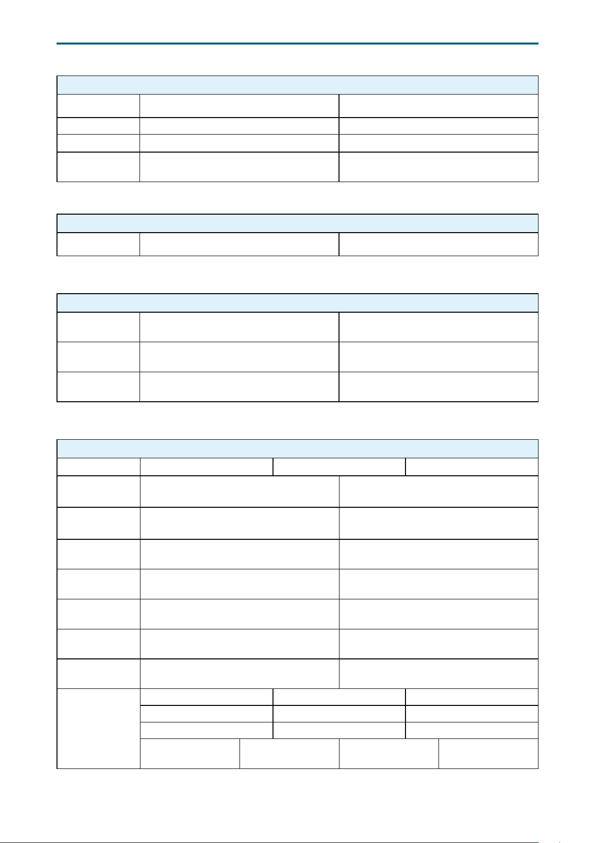
Chapter 4. BIOS Conguration SettingsLynx User Manual
4.4.2 Peripheral Conguration
Peripheral Configuration
PCIe SR-IOV Enable Disable
PCIe ARI Enable Disable
ARI Forward Enable Disable
Spread
Spectrum
Enable Disable
4.4.3 Video Conguration
Video Configuration
Display Mode Plug In First On Board First
4�4�4 ACPI Table/Features Control
ACPI Table/Features Control
APIC - IO APIC
Mode
SPCR Table
Support
HPET Table
Support
Enable Disable
Enable Disable
Enable Disable
4�4�5 System Event Log
System Event Log
System Errors Auto Enable Disable
System
Memory Poison
Viral Status Enable Disable
Clear Viral
Status
System
Cloaking
Ubox To Pcu
Mca Enabling
CATERR→GPIO
→
SMI
Fatal Err Debug
Halt
eMCA Settings
Enable Disable
Enable Disable
Enable Disable
Enable Disable
Enable Disable
Enable Disable
EMCA Logging Support Enable Disable
LMCE Support Enable Disable
Ignore OS EMCA Opt-in Enable Disable
EMCA CMCI-SMI
Morphing
EMCA gen 1 Lite EMCA gen 2 CSMI Disable
36
Page 45

Chapter 4. BIOS Conguration SettingsLynx User Manual
eMCA Settings
Whea Settings
Error Injection
Settings
UPI Error
Enabling
Memory Error
Enabling
EMCA MCE-SMI
Enable
Corrected Error eLog Enable Disable
Memory Error eLog Enable Disable
Processor Error eLog Enable Disable
WHEA Support Enable Disable
Whea Log Memory Error Enable Disable
Whea Log Processor Error Enable Disable
Whea Log PCI Error Enable Disable
Mca Bank Error Injection
Support
WHEA Error Injection
Support
WHEA Error Injection 5.0
Extension
Whea PCIE Error Injection
Support
Whea PCIe Error Injection
Action Table
ME Seg Error Injection
Support
Enable HA Parity Check Enable Disable
Mca Bank Warm Boot
Clear Errors
SMI UPI Lane Failover Enable Disable
Memory Error Enable Disable
Memory Corrected Error Enable Disable
Memory Leaky Bucket
Value
Spare Interrupt
NVMCTLR Errors Enable Disable
NVMCTLR Low
Priority Error
Signaling
NVMCTLR High
Priority Error
Signaling
Set NGN Address Range
Scrub
Set NGN Host Alert Policy
for AIT Error
Set NGN Host Alert Policy
for DPA Error
EMCA gen 1 Dual
Mode
Enable Disable
Enable Disable
Enable Disable
Enable Disable
Enable Disable
Enable Disable
Enable Disable
Min=0x0, Max=0xffff
Error Pin CMCI
SMI Disable
ERR0# Pin SMI Disable
ERR0# Pin SMI Disable
Enable Disable
Poison Viral
Poison Viral
EMCA gen 2 -
MSMI
Disable
37
Page 46

Chapter 4. BIOS Conguration SettingsLynx User Manual
IIO Error
Enabling
PCIe Error
Enabling
IIO/PCH Global Error
Support
IIO MCA Support Enable Disable
IIO Error Pin Programming Enable Disable
IIO Error Registers Clear Enable Disable
IIO LER Support Enable Disable
LER MA Error Logging Enable Disable
IIO Coherent Interface
Error
IIO IRP0 protocol parity
error
IIO IRP0 protocol qt
overflow underflow error
IIO IRP0 protocol rcvd
unexprsp
IIO IRP0 csr acc 32b
unaligned
IIO IRP0 wrcache
uncecccs0 error
IIO IRP0 wrcache
uncecccs1 error
IIO IRP0 protocol rcvd
poison error
IIO IRP0 wrcache
correcccs0 error
IIO IRP0 wrcache
correcccs1 error
IIO Misc. Error Enable Disable
IIO Vtd Error Enable Disable
IIO Dma Error Enable Disable
IIO Dmi Error Enable Disable
PCIE Error Enable Disable
IIO PCIE Additional
Corrected Error
IIO PCIE Additional
Uncorrected Error
IIO PCIE AER Spec
Compliant
Corrected Error Enable Disable
Uncorrected Error Enable Disable
Fatal Error Enable Enable Disable
PCIE Corrected Error
Threshold Counter
PCIE Corrected Error
Threshold Mask
PCIE Corrected Error
Threshold
Enable Disable
Enable Disable
Enable Disable
Enable Disable
Enable Disable
Enable Disable
Enable Disable
Enable Disable
Enable Disable
Enable Disable
Enable Disable
Enable Disable
Enable Disable
Enable Disable
Enable Disable
Min=0x0, Max=0x3f
Min=0x0, Max=0x7fff
38
Page 47
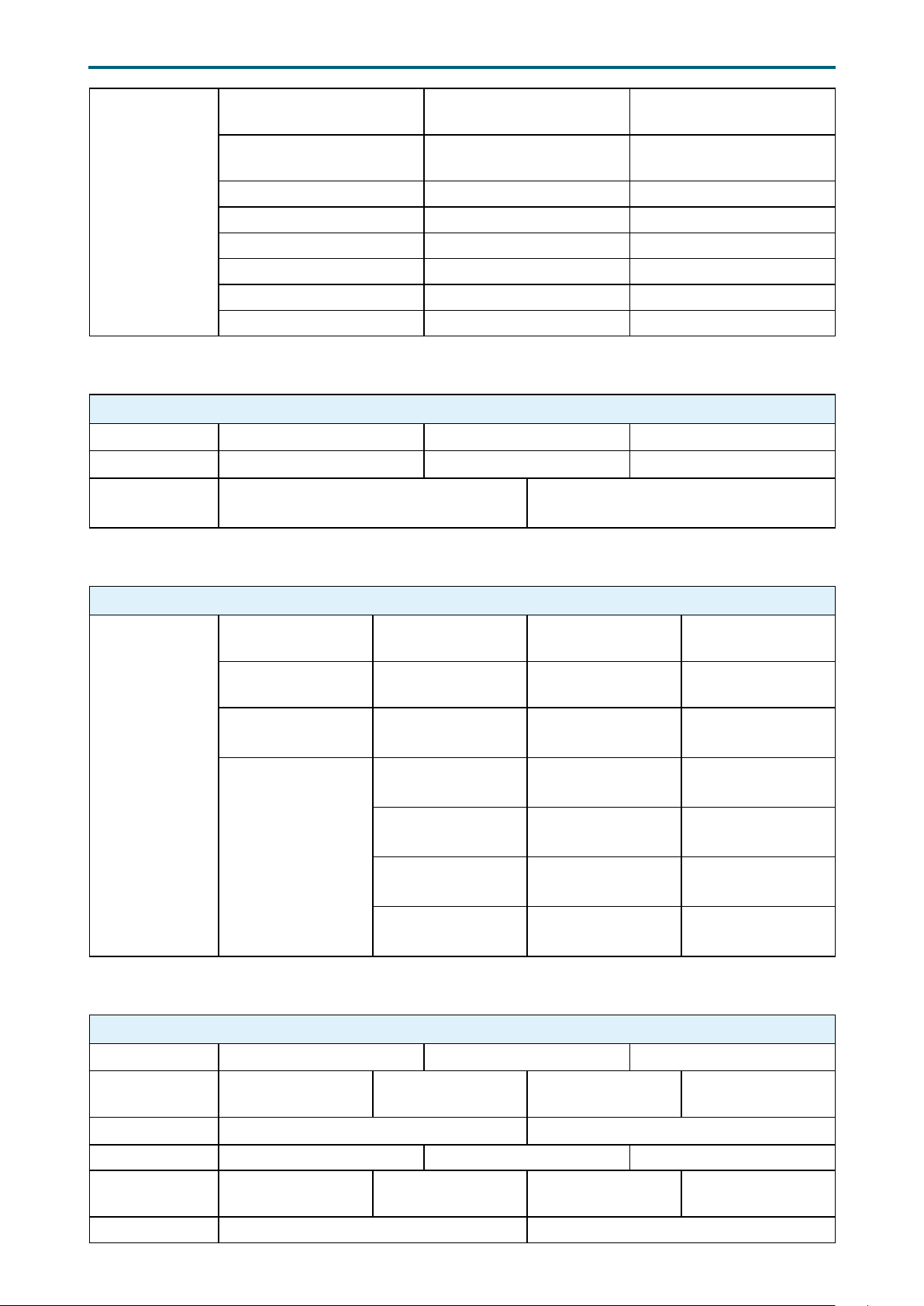
Chapter 4. BIOS Conguration SettingsLynx User Manual
PCIe Error
Enabling
PCIE AER Corrected
Errors
PCIE AER Advisory
Nonfatal Error
PCIE AER Nonfatal Error Enable Disable
PCIE AER Fatal Error Enable Disable
SERR Propagation Enable Disable
PERR Propagation Enable Disable
Signal to OS on SERR Enable Disable
Signal to OS on PERR Enable Disable
Enable Disable
Enable Disable
4�4�6 Debug Conguration
Debug Conguration
RAM 0 1 None
Trace Hub 0 1 None
Additional Post
Codes
Enable Disable
4�4�7 OEMBOARD Function
SMBIOS Updated
Function
BOOT Retry
Function
SMBIOS TO BMC
Redsh
Messiah
Function
Manufacturing
Function
4�4�8 SIO AST2500
OEMBOARD Function
SMBIOS Updated Auto By Utility
BOOT Retry Enable Disable
Write SMBIOS to
BMC
Manufacturing
Test Mode
Dumped Storage USB Storage SATA Storage
USB Test Function Enable Disable
SATA Test
Function
Enable Disable
Enable Disable
Enable Disable
SIO AST2500
Serial Port A Auto Enable Disable
Base I/O
Address
Interrupt IRQ3 IRQ4
Serial Port B Auto Enable Disable
Base I/O
Address
Interrupt IRQ3 IRQ4
2E8 2F8 3E8 3F8
2E8 2F8 3E8 3F8
39
Page 48

Chapter 4. BIOS Conguration SettingsLynx User Manual
Serial Port D Auto Enable Disable
Base I/O
Address
Interrupt IRQ7 IRQ10
2E8 2F8 3E8 3F8
4�4�9 Socket Conguration
Socket Conguration
Hyper-Threading
[ALL]
Check CPU BIST
Result
3StrikeTimer Enable Disable
Fast String Enable Disable
Monitor/Mwait Enable Disable
Machine Check Enable Disable
Execute Disable Bit Enable Disable
Enable Intel(R) TXT Enable Disable
Enable Disable
Enable Disable
Processor
Conguration
Per-Socket
Conguration
VMX Enable Disable
Enable SMX Enable Disable
Lock Chipset Enable Disable
MSR Lock Control Enable Disable
Hardware
Prefetcher
Adjacent Cache
Prefetch
DCU Streamer
Prefetcher
DCU IP Prefetcher Enable Disable
LLC Prefetch Enable Disable
DCU Mode
Bsp Selection
Extended APIC Enable Disable
Enable Disable
Enable Disable
Enable Disable
32KB 8Way
Without ECC
Auto
Socket 0
Socket 1
16KB 4Way With
ECC
Socket 2
Socket 3
AES-NI Enable Disable
APIC Physical
Mode
Virtual Wire Mode Virtual Wire A Virtual Wire B
Down Stream PECI Enable Disable
PECI IN TRUST BIT
ENABLE
Targeted Smi Enable Disable
eSMM Save State Enable Disable
Smbus Error
Recovery
Enable Disable
Enable Disable
Enable Disable
40
Page 49
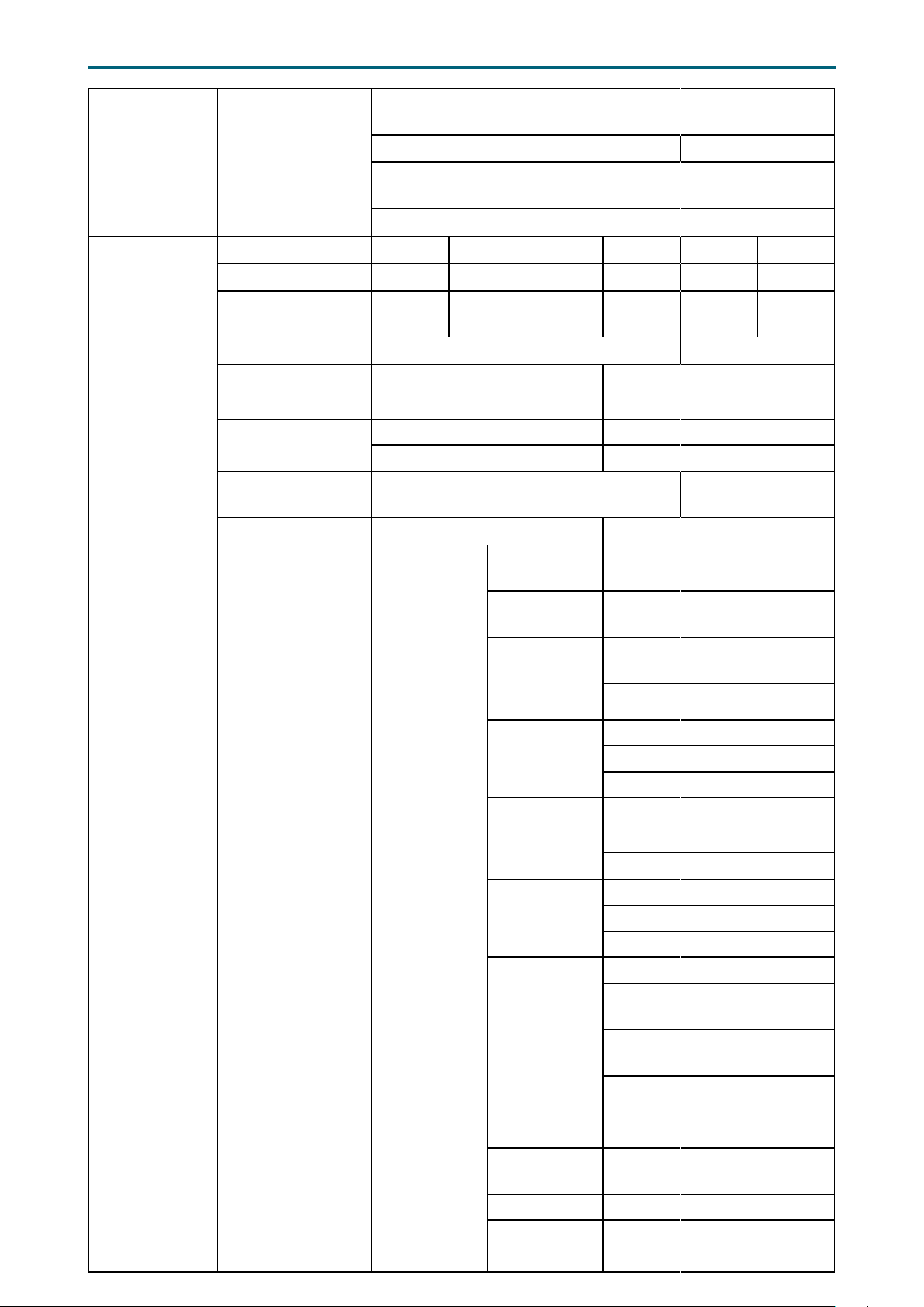
Chapter 4. BIOS Conguration SettingsLynx User Manual
Processor
Conguration
Common
RefCode
Conguration
Core Disable
Bitmap(Hex)
CPU Socket
0/1/2/3
Conguration
MMCFG Size 64M 128M 256M 512M 1G 2G
MMIO High Base 1T 4T 16T 24T 40T 56T
MMIO High
Granularity Size
Isoc Mode Auto Enable Disable
Numa Enable Disable
Publish SRAT Enable Disable
Serial Debug
Message Level
Trace Messages Enable
Training Messages Enable Disable
IOT Cfg Enable Disable
Num of OCLA
Ways
OCLA Tor IDs Min=0, Max=17
1G 4G 16G 64G 256G 1024G
Normal Maximum
Disable Minimum
Min=0x0, Max=0xfffffff
Min=0, Max=8
Enable for registry
writes only
Disable
UPI
Conguration
UPI General
Conguration
UPI Status
Degrade
Precedence
Link Speed
Mode
Link
Frequency
Select
Link L0p
Enable
Link L1
Enable
UPI Failover
Support
IO Directory
Cache (IODC)
Directory
Mode Enable
SNC Enable Disable
XPT Prefetch Enable Disable
41
KTI Prefetch Enable Disable
Topology
Precedence
Slow Fast
Auto
9.6GB/s 10.4GB/
Auto
Enable
Disable
Auto
Enable
Disable
Auto
Enable
Disable
Auto
Enable for Remote InvItoM
Hybrid Push
Enable for Remote InvItoM
AllocFlow
Enable for Remote InvItoM
Hybrid
Disable
Enable Disable
Feature
Precedence
Use Per Link
Setting
Page 50
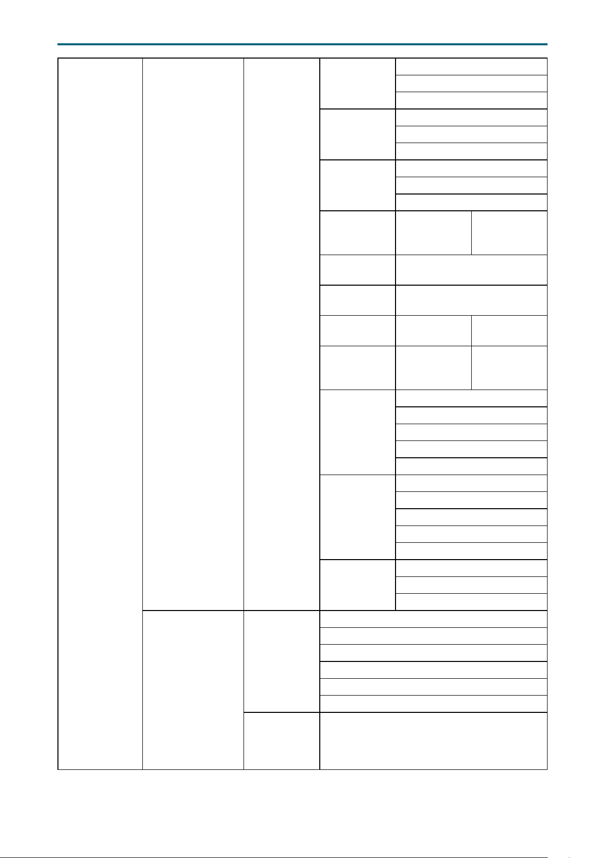
UPI
Conguration
UPI General
Conguration
UPI Per Socket
Conguration
UPI Status
CPU 0
CPU 1
CPU 2
CPU 3
Bus
Resources
Allocation
Ratio
Chapter 4. BIOS Conguration SettingsLynx User Manual
Auto
RdCur for XPT
Prefetch
UPI VNA
Credit
Override
CRC Mode
UPI Load
Board for
Failed Links
Legacy VGA
Socket
Legacy VGA
Stack
MMIO P2P
Disable
CPU SKU Type
Mismatch
check
UPI Debug
Print Level
Local/Remote
Threshold
TSC Sync
support
CPU 0 UPI Port 0
CPU 0 UPI Port 0 DFX
CPU 0 UPI Port 1
CPU 0 UPI Port 1 DFX
CPU 0 UPI Port 2
CPU 0 UPI Port 2 DFX
Min=0, Max=8
Enable
Disable
Maximun
Minimun
Per Link
Auto
16 Bit CRC
32 Bit rolling CRC
Enable Disable
Min=0, Max=3
Min=0, Max=6
Yes No
Yes No
All
Detail
Summary
Warning
Fatal
Auto
Low
Medium
High
Disable
Auto
Enable
Disable
42
Page 51

UPI
Conguration
Memory
Conguration
UPI Dfx
Conguration
Integrated Memory
Controller (iMC)
Chapter 4. BIOS Conguration SettingsLynx User Manual
Halt at UPI
Link Train
Failure
UPI Max Init
Abort
Llc Share
Drd Crd
CBo Bias Fwd
Mode
Snoop Fanout Auto Enable Disable
Hit Me Auto Enable Disable
Enable Force
FwdInvItoE
DBP Enabled Auto Enable Disable
OSB Enabled Auto Enable Disable
HitME RFO
DirS Enabled
Gate OSB
IODC
Allocation
Enabled
Dual Link
Interleave
Mode
Dfx System
Degrade
Mode
VN1 Auto Enable Disable
Direct To Core
(D2C)
Direct To UPI
(D2K)
Enforce POR Auto Por Disable
PPR Type
PPR Error
Injection test
Memory
Frequency
IMC BCLK Auto 100MHz 133MHz
MRC Promote
Warnings
Promote
Warnings
Halt on mem
Training Error
Auto Enable Disable
Auto Enable Disable
Auto Enable Disable
Auto Mode 0 Mode 1
Mode 2 Mode 3 Mode 4
Auto Enable Disable
Auto Enable Disable
Auto Enable Disable
Enable CHA
interleaving
Auto Disable D2C
Degrade_
to_1S
Auto Enable Disable
Auto Enable Disable
Auto Hard PPR
Soft PPR PPR Disabled
Enable Disable
Auto 800~4400-OvrClk
Enable Disable
Enable Disable
Enable Disable
Degarde_to_
Supported
(disable SNC,
XOR-based
Intlv)
No_Degrade
43
Page 52

Memory
Conguration
Integrated Memory
Controller (iMC)
Chapter 4. BIOS Conguration SettingsLynx User Manual
MultiThreaded
MRC
SPD CRC
Check
Enhanced Log
Parsing
LRDIMM
Module Delay
Mem Test Auto Enable Disable
Mem Test
Loops
Memory Type RDIMMs only UDIMMs only
Rank Margin
Tool
Backside
RMT
Backside
CMD RMT
RMT Pattern
Length
RMT Pattern
Length CMD
CTL VREF
Per Bit Margin Auto Enable Disable
NVMDIMM
BCOM
Margining
Support
Attempt Fast
Boot
Attempt Fast
Cold Boot
Mem Test On
Fast Boot
RMT On Cold
Fast Boot
Auto Enable Disable
Auto Enable Disable
Enable Disable
Auto Disable
Min=0, Max=65535
UDIMMs and
RDIMMs
Auto Enable Disable
Enable Disable
Enable Disable
Min=1, Max=9000000
Min=1, Max=9000000
Enable Disable
Auto Enable Disable
Auto Enable Disable
Auto Enable Disable
Auto Enable Disable
BDAT Enable Disable
Data
Scrambling
for
NVMDIMM
Data
Scrambling
for DDR4
Allow
Correctables
Auto Enable Disable
Auto Enable Disable
Auto Enable Disable
44
Page 53

Memory
Conguration
Integrated Memory
Controller (iMC)
Chapter 4. BIOS Conguration SettingsLynx User Manual
WR CRC
feature
Control
DIMM
Isolation
Enable
Scrambling
Seed Low
Scrambling
Seed High
Enable ADR Enable Disable
Legacy ADR
Mode
ADR Data
Save Mode
Erase-Arm
NVDIMMs
Restore
NVDIMMs
Interleave
NVDIMMs
Custom
Refresh
Enable
Custom
Refresh Rate
SMB Clock
Frequency
DDR Cycling Enable Disable
Mem Flows Min=0x0, Max=0xffffffff
Mem Flows
Ext
DIMM Rank
Enable Mask
Socket 0
Channel 0~5
Rank Enable
Bit Mask
Socket 1
Channel 0~5
Rank Enable
Bit Mask
Socket 2
Channel 0~5
Rank Enable
Bit Mask
Socket 3
Channel 0~5
Rank Enable
Bit Mask
Auto Enable Disable
Auto Enable Disable
Min=0, Max=65535
Min=0, Max=65535
Enable Disable
NVDIMMs
Enable Disable
Enable Disable
Enable Disable
Enable Disable
Min=20, Max=40
Auto 100 Khz
400 Khz 1 Mhz
Min=0x0, Max=0xffffffff
Enable Disable
Min=0x0, Max=0xff
Battery
backed DIMM
Disable
45
Page 54
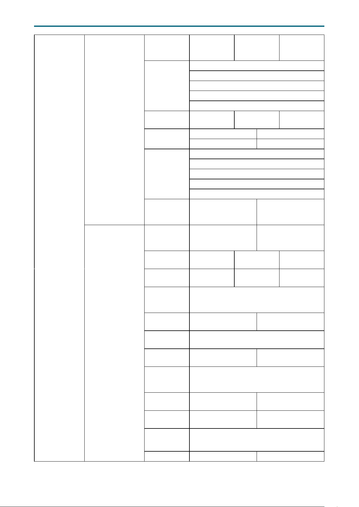
Memory
Conguration
Memory Map
Memory RAS
Conguration
Setup
Chapter 4. BIOS Conguration SettingsLynx User Manual
Volatile
Memory
Auto 1LM 2LM
Mode
Auto
1LM Memory
Interleave
Granularity
64B Target
64B Channel
256B Target
256B Channel
IMC
Interleaving
Channel
Interleaving
Auto
Auto 1-way Interleave
2-way Interleave 3-way Interleave
1-way
Interleave
Auto
1-way Interleave
Rank
Interleaving
2-way Interleave
4-way Interleave
8-way Interleave
Socket
Interleave
Enable Disable
Below 4GB
Static Virtual
Lockstep
Enable Disable
Mode
Mirror mode
Enable Partial
Mirror
Mirror Mode
1LM
Partial Mirror
Mode 1LM
Mirror Mode
2LM
Partial Mirror
Mode 2LM
Partial
Mirror1~4
Min=0, Max=65535
Size in GB
UEFI ARM
Mirror
ARM Mirror
percentage
Memory Rank
Sparing
Enable Disable
Min=0, Max=5000
Enable Disable
Correctable
Error
Min=0x0, Max=0x7fff
Threshold
SDDC Plus
One
ADDDC
Sparing
NGN Die
Sparing
Aggressiveness
Enable Disable
Enable Disable
Min=0, Max=255
Patrol Scrub Enable Disable
2-way
Interleave
Disable
Disable
46
Page 55
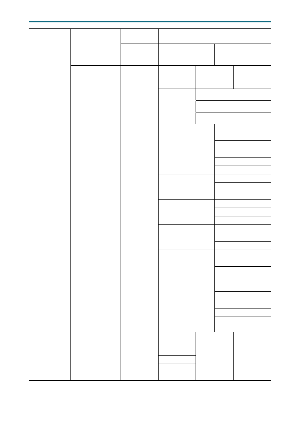
Chapter 4. BIOS Conguration SettingsLynx User Manual
Memory
Conguration
Memory RAS
Conguration
Setup
NGN Conguration
Patrol Scrub
Interval
Patrol Scrub
Address
Mode
NGNVM
DIMM Secure
Erase Unit
Min=0, Max=24
Reverse Address
Set TDP
DIMM power
limit
ARS on Boot
Lock NGN CSRs
Debug lock for NGN
NGN CMD Time
NGN ECC Correctable
error
NGN ECC Write Check
NGN ECC Read Check
CR QoS Conguration
Erase All
DIMMs
S0 CH0~5
S1 CH0~5
S2 CH0~5
S3 CH0~5
10W 12W
15W 18W
Auto
Enable
Disable
Enable Disable
Enable Disable
System Physical
Address
Auto
Enable
Disable
Auto
Enable
Disable
Auto
1N
2N
Auto
Enable
Disable
Auto
Enable
Disable
Auto
Enable
Disable
Option 1
Option 2
Option 3
Option 4
Option 5
Default (no QoS
optimization)
47
Page 56
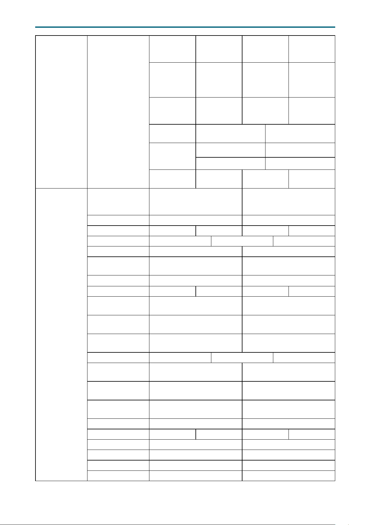
Chapter 4. BIOS Conguration SettingsLynx User Manual
Memory
Conguration
DIMM
Management
Load NGN
DIMM
Management
Drivers
Memory Dfx
Conguration
PCI 64-Bit
Resource
Allocation
PCIe Train by BIOS Yes No
PCIe Hot Plug Auto Manual Enable Disable
PCIe ACPI Hot Plug Per-port Enable Disable
MultiCast Enable Enable Disable
MC BaseAddress
Range
Persistent
Memory
Mode
NVMDIMM
Partitioning
Low Mem
Channel
Cong
CR Halt/Warn
Mixed SKU
Enable Disable
Auto Below_4G
Auto BIOS Setup
Auto Enable Disable
Auto Enable Disable
Enable Disable
Auto Channel 0
Channel 1 Channel 2
Auto Enable Disable
NGN DIMM
Management
Driver
IIO
Conguration
MC Index Position 12 20
MC Num Group 1 8 32 64
No Snoop Read
Cong
NoSnoop Write
Cong
Max Read Comp
Comb Size
Problematic port P-P problematic NP-NP problemati Disable
DMI Allocating
Write Flows
PCIe Allocating
Write Flows
Skip Halt On DMI
Degradation
Rx Clock WA Enable Disable
PME2ACK Timeout 1 ms 10 ms 50 ms Test Mode
MCTP Enable Disable
Hide PCU Func 6 Enable Disable
EN1K Enable Disable
Dual CV IO Flow Enable Disable
Enable Disable
Enable Disable
Minimum Maximum
Allocating Non-Allocating
Allocating Non-Allocating
Enable Disable
48
Page 57

Chapter 4. BIOS Conguration SettingsLynx User Manual
IIO
Conguration
PCIE Coherent
Read Partial
PCIE Coherent
Read Full
PCI-E Completion
Timeout (Global)
Disable
PCI-E Global
Timeout Value
PCI-E ASPM
Support (Global)
PCIE Stop &
Scream Support
Snoop Response
Hold Off
PCIe Latency
Tolerance
Reporting
PCIe Extended Tag
Enable
PCIe Atomic
Operation Request
Support
PCIe Max Read
Request Size
PcIe Relaxed
Ordering
PCIe PHY test
mode
Socket0/1
Conguration
PCIRd Cur Setting, PRd Setting
PCIRd Cur Setting, PRd Setting
Per-port Yes No
50m~64s
Per-port L1 Only Disable
Enable Disable
Min=0x0, Max=0xf
Auto Enable Disable
Auto Enable Disable
Enable Disable
Auto
Enable Disable
Enable Disable
Auto x4x4x4x4
IOU0 (IIO PCIe Br1)
IOU1 (IIO PCIe Br2)
IOU2 (IIO PCIe Br3)
MCP0 (IIO PCIe
Br4)
MCP1 (IIO PCIe
Br5)
x4x4x8 x8x4x4
x8x8 x16
Auto x4x4x4x4
x4x4x8 x8x4x4
x8x8 x16
Auto x4x4x4x4
x4x4x8 x8x4x4
x8x8 x16
Auto x16
Auto x16
128B, 256B, 512B, 1024B,
2048B, 4096B
PCI-E Completion
Timeout Disable
PCI-E Completion
Timeout Value
49
Yes No
50μs to 10ms,16ms to 55ms,65ms to
210ms,260ms to 900ms,1s to 3.5s,4s
to 13s,17s to 64s
Page 58

Chapter 4. BIOS Conguration SettingsLynx User Manual
Intel® VT for
Directed I/O (VT-d)
Intel® VMD
technology
IIO IOAPIC Stack
0~5
Intel® VT for
Directed I/O (VT-d)
Interrupt
Remapping
PassThrough DMA Enable Disable
ATS Enable Disable
Posted Interrupt Enable Disable
Coherency Support
(Non-Isoch)
Intel® VMD
for Volume
Management
Device on
Socket 0/1
Enable Disable
Enable Disable
Enable Disable
Enable Disable
Intel® VMD
for Volume
Management
Device for
PStack0
VMD port A
VMD port B
VMD port C
VMD port D
Hot Plug
Capable
Cfg Bar size
Cfg Bar
attribute
VMD
Cong for
PStack0~2
Cfg Bar
attribute
Mem Bar 1
size
Mem Bar 1
attribute
Mem Bar 2
size
Mem Bar 2
attribute
Enable
Disable
Enable
Disable
Enable
Disable
Min=20,
Max=27
64-bit
prefetchable
32-bit non-
prefetchable
64-bit non-
prefetchable
64-bit
prefetchable
Min=20,
Max=39
32-bit non-
prefetchable
64-bit non-
prefetchable
64-bit
prefetchable
Min=20,
Max=39
32-bit non-
prefetchable
64-bit non-
prefetchable
64-bit
prefetchable
50
Page 59
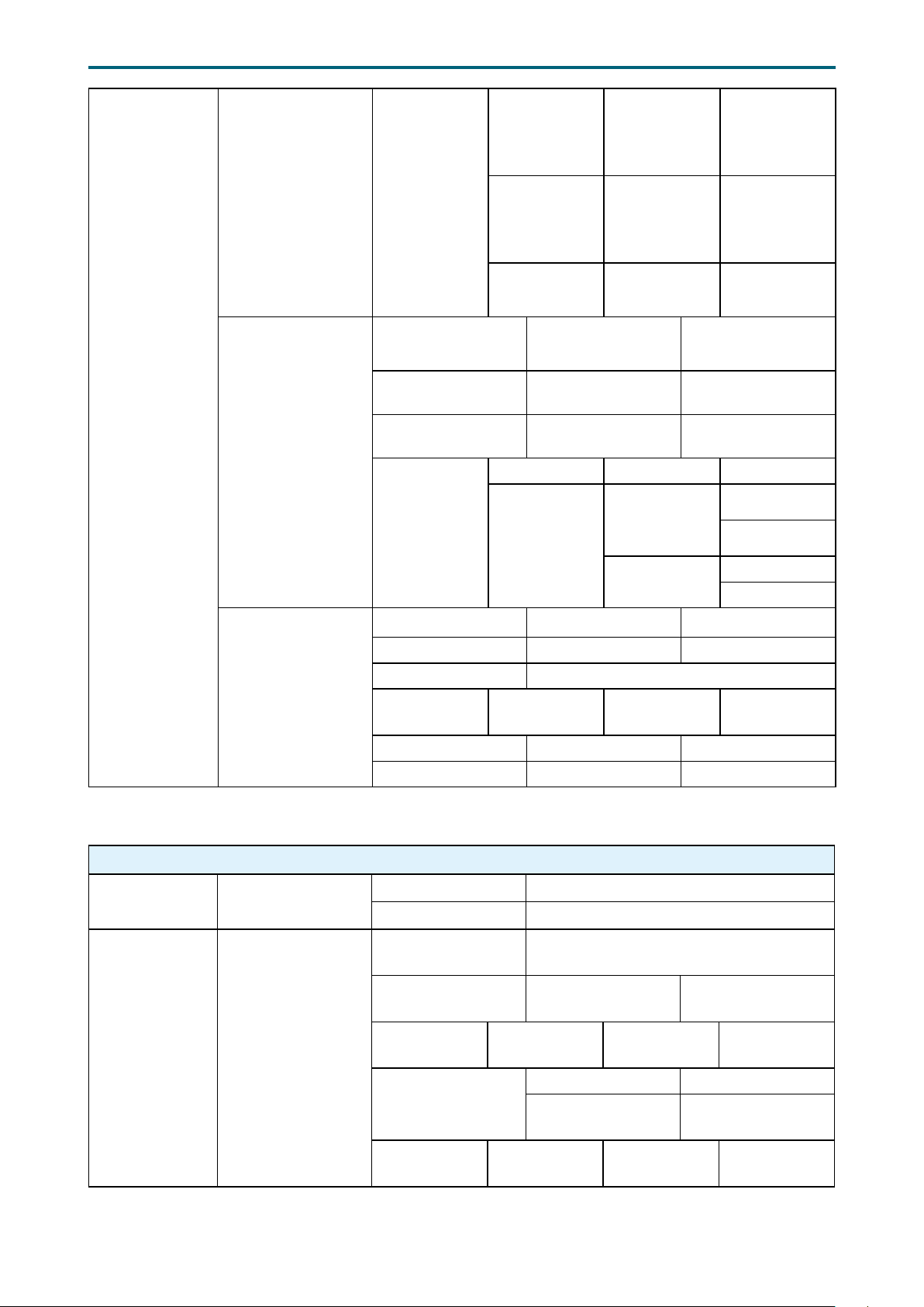
Intel® AIC
Retimer/AIC SSD
Technology (nonVMD)
Intel® AIC
Retimer/
AIC SSD on
Socket 0~1
Chapter 4. BIOS Conguration SettingsLynx User Manual
Intel® AIC
Retimer/AIC
SSD HW at
PStack0~2
Port A
Port B
Port C
Port D
Enable Disable
Enable Disable
Intel® VMD
technology
FIOAT
Conguration)
IIO DFX
Conguration
Hot Plug
Capable
Disable TPH Yes No
Prioritize TPH Enable Disable
Relaxed Ordering Enable Disable
DCA Enable Disable
Sck0~1 IOAT
Cong
EV DFX Features Enable Disable
Ltssm Logger Enable Disable
Stop Min=0x0, Max=0x99
Speed
Mask Enable Disable
Jitter Logger Enable Disable
IOAT Function
1~7 Items
Gen 1 (2.5
GT/s)
Enable Disable
Enable
DMA
Disable
Enable
No snoop
Disable
Gen 2 (5 GT/s)Gen 3 (8 GT/
s)
4.4.10 ME Conguration
Server ME
Conguration
Server ME
Debug
Conguration
General ME
Conguration
Server ME General
Conguration
ME Conguration
Altitude Min=0x0, Max=0xffff
MCTP Bus Owner Min=0x0, Max=0xffff
ME Initialization
Complete Timeout
Enable HSIO
Messaging
DRAM Init
Done Enable
DRAM Initialization
Status
Host Reset
Warning
Min=0, Max=12
Enable Disable
0 1 None
Auto - true status 0 - Success
1 - No Memory in
Channels
0 1 None
51
2 - Memory Init
Error
Page 60
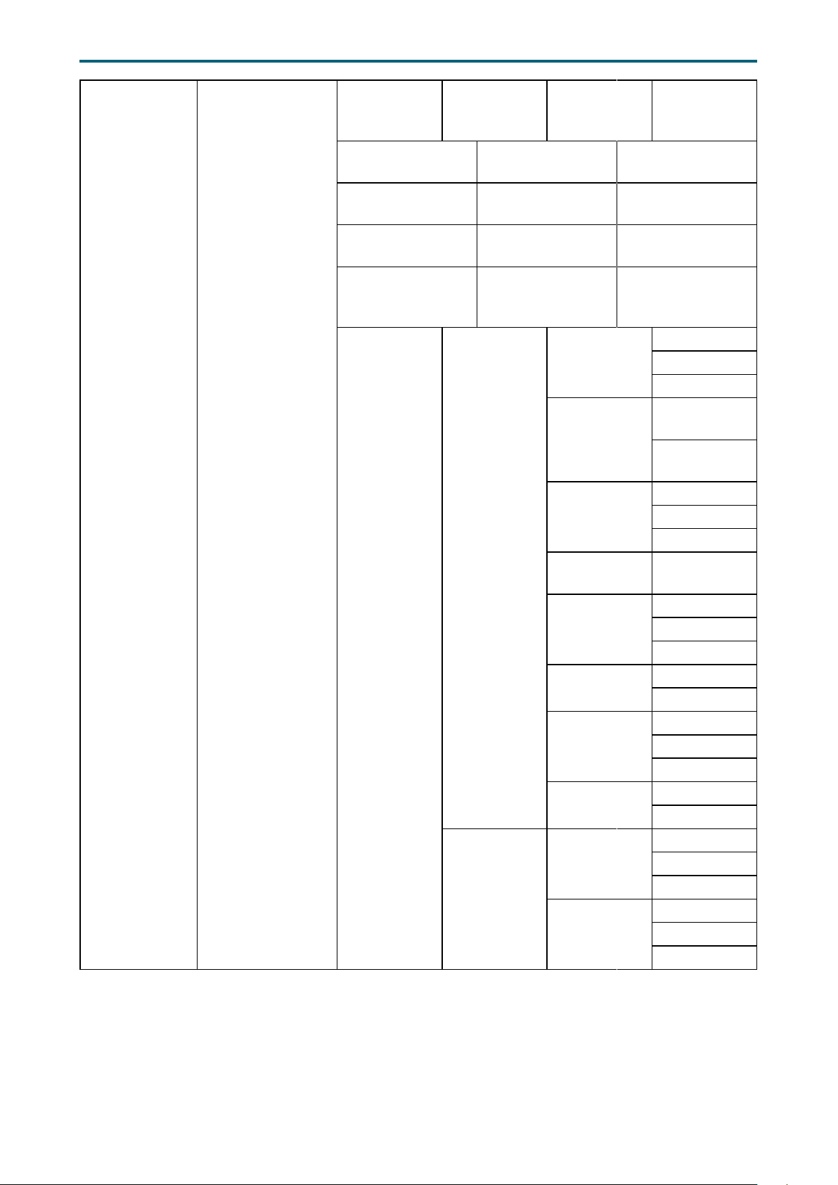
Server ME
Debug
Conguration
Server ME General
Conguration
Enable PreDramInitDone
ME Reset
HMRFPO_LOCK
Message
HMRFPO_ENABLE
Message
END_OF_POST
Message
HECI-1 Enable
HECI-2 Enable
HECI-3 Enable
Override
ICC Clock
Settings
0 1 None
NM
Conguration
Override
ICC Clock
Settings
Chapter 4. BIOS Conguration SettingsLynx User Manual
Enable Disable
Enable Disable
Enable Disable
Enable Disable
0
Boot Mode
Override
Boot Mode
Cores Disable
Override
Cores To
Disable
Power
Measurement
Override
Power
Measurement
Hardware
Change
Override
Hardware
Changed
Override
ICC Clock
Settings
ICC Clock
Spread
Spectrum
1
None
Performance
Optimized
Power
Optimized
0
1
None
Min=0x0
Max=0x7f
0
1
None
Enable
Disable
0
1
None
Yes
No
0
1
None
0
1
None
52
Page 61
4�4�11 PCH Conguration
DCI enable
(HDCIEN)
DCI Auto Detect
Enable
PCH Devices
Enable Disable
Enable Disable
PCH Server Error
Reporting Mode
(SERM)
CLKRUN# logic Enable Disable
Serial IRQ Mode Queit Continuous
PCH state after G3 S0 S5 Last State
Port 80h
Redirection
PCH Cross
Throttling
PCH CRID Enable Disable
IO-APIC 24-119
RTE
Pcie Pll SSC Enable Disable
PCI Delay
Optimization
Compliance Test
Mode
PCI-E ASPM
Support (Global)
CTO for Uplink x16
CTO for Uplink x8
Chapter 4. BIOS Conguration SettingsLynx User Manual
PCH Configuration
Enable Disable
LPC Bus PCI Mode
Enable Disable
Enable Disable
Enable Disable
Enable Disable
Per individual port L1 Only
40-50ms(spec 50us-50ms),40-50ms(spec 16ms-55ms),160170ms(spec 65ms-210ms),400-500ms(spec 260ms900ms),1.6-1.7s(spec 1s-3.5s),Disabled
PCI Express
Conguration
MPL for Uplink x16
MPL for Uplink x8
PCIE Clock Gating Enable Disable
PCH DMI ASPM Platform-POR ASPM L1 Disable
DMI Link Extended
Synch Control
Stop and Scream Enable Disable
Expanded SPI TPM
Transaction Length
Enable
Subtractive
Decode
Subtractive Decode
Port#
PCIe Root Port
Function Swapping
Max Read Request
Size
MPL 128B MPL 256B MPL 512B
Enable Disable
Enable Disable
Enable Disable
Min=0, Max=7
Enable Disable
MRRS 128B MRRS 256B MRRS 512B
MRRS 1024B MRRS 2048 MRRS 4096
53
Page 62
PCH SATA
Conguration
Chapter 4. BIOS Conguration SettingsLynx User Manual
SATA Controller Enable Disable
Congure SATA as AHCI RAID
SATA test mode Enable Disable
Support
Aggressive
Link Power
Management
Port .~7 Enable Disable
SATA Port 0
DevSlp
Hot Plug Enable Disable
Congure as
eSATA
Mechanical
Presence Switch
Spin Up Device Enable Disable
SATA Device Type Hard Disk Drive Solid State Drive
SATA Topology
SATA Mode
options
Enable Disable
Enable Disable
Enable Disable
Enable Disable
Unknown
ISATA
Direct Connect
Flex
M2
SATA HDD
Unlock
SATA Led
locate
RAID 0 Enable Disable
Enable Disable
Enable Disable
SATA Mode
Options
RAID 1 Enable Disable
RAID 5 Enable Disable
RAID 10 Enable Disable
Intel Rapid
Recovery
Technology
RAID Option
ROM UI
banner
IRRT Only on
ESATA
Smart
Response
Technology
RAID OROM
prompt delay
Enable Disable
Enable Disable
Enable Disable
Enable Disable
2 Seconds 4 Seconds
6 Seconds 8 Seconds
54
Page 63
Chapter 4. BIOS Conguration SettingsLynx User Manual
sSATA Controller Enable Disable
Congure SATA as AHCI RAID
SATA test mode Enable Disable
Support
Aggressive
Link Power
Management
Port 0~5 Enable Disable
Hot Plug Enable Disable
Congure as
eSATA
Spin Up Device Enable Disable
sSATA Device Type Hard Disk Drive Solid State Drive
SATA Topology
Enable Disable
Enable Disable
Unknown
ISATA
Direct Connect
Flex
PCH sSATA
Conguration
SATA Mode
options
SATA Mode
Options
M2
SATA HDD
Unlock
SATA Led
locate
RAID 0 Enable Disable
RAID 1 Enable Disable
RAID 5 Enable Disable
RAID 10 Enable Disable
Intel Rapid
Recovery
Technology
RAID Option
ROM UI
banner
IRRT Only on
ESATA
Smart
Response
Technology
RAID OROM
prompt delay
Enable Disable
Enable Disable
Enable Disable
Enable Disable
Enable Disable
Enable Disable
2 Seconds 4 Seconds
6 Seconds 8 Seconds
55
Page 64

Chapter 4. BIOS Conguration SettingsLynx User Manual
USB Precondition Enable Disable
XHCI Manual Mode Enable Disable
Trunk Clock Gating
(BTCG)
Enable USB 3.0
pins
USB 3.0 pin
#1~#10
Enable Disable
Enable Disable
Enable Disable
USB
Conguration
Security
Conguration
Platform
Thermal
Conguration
Trace Hub
Conguration
Menu
PCH DFX
Conguration
USB Per-Connector
Disable
USB HS Physical
Connector #0~13
Disable
USB SS Physical
Connector #0~9
Disable
USB XHCI MSI
Disable WA
XHCI Over Current
Pins
XHCI Wake On Usb
Enable
Place XHCI BAR
below 4GB
SMM BIOS Write
Protect
PCH Thermal
Device
Trace Hub Enable
Mode
MemRegion 0/1
Buffer Size
Reveal PCH P2SB
device
Unlock PCH P2SB Enable Disable
PMC Read Disable Enable Disable
SPD Write Disable Enable Disable
Hide Trace Hub Enable Disable
GPIO Lockdown Enable Disable
RTC Lock Enable Disable
BIOS Lock Enable Disable
Gbe Flash Lock-
Down
Unlock Thermal
Registers
Flash Lock-Down Auto Enable Disable
MROM 0/1 Hook Enable Disable
Enable Disable
Enable Disable
Enable Disable
Enable Disable
Enable Disable
Enable Disable
Enable Disable
Enable Disable
Auto
Target Debugger Host Debugger Disable
1MB 5MB 8MB 64MB
Enable Disable
Enable Disable
Enable Disable
Enabled in
ACPI mode
Enabled in
PCI mode
Disable
56
Page 65

Chapter 4. BIOS Conguration SettingsLynx User Manual
PCH DFX
Conguration
MCTP Broadcast
Cycle
DMI Link Down
Hang Bypass
(DLDHB)
LTR Conguration
Enable Disable
Enable Disable
Enable/
Disable ADR
ADR GPIO GPIO B GPIO C
Enable/
Disable ADR
Timer
ADR timer
expire time
ADR timer
multiplier
PCH
SATA LTR
Conguration
Platform-POR Enable Disable
Platform-POR Enable Disable
Platform-POR 25 uS 50 uS
100 uS
Platform-POR x1 x8
x24 x40 x56
x64 x72 x80
x88 x96
PCH SATA
LT R
SATA LTR
Override
SATA Snoop
Latency Value
SATA Snoop
Latency
Multiplier
Enable Disable
Enable Disable
Min=0, Max=1023
1 ns 32 ns
1024 ns 32768 ns
1048576 ns 33554432 ns
0 uS
PCH
sSATA LTR
Conguration
CPU PCIe LTR
Override
SATA LTR
Lock
PCH sSATA
LT R
sSATA LTR
Override
sSATA Snoop
Latency Value
sSATA Snoop
Latency
Multiplier
sSATA LTR
Lock
PCH
PCIE1~20
LT R
Force LTR
Override
PCIE1~20
Enable Disable
Enable Disable
Enable Disable
Min=0, Max=1023
1 ns 32 ns
1024 ns 32768 ns
1048576 ns 33554432 ns
Enable Disable
Enable Disable
Enable Disable
57
Page 66
Chapter 4. BIOS Conguration SettingsLynx User Manual
4�4�12 H2O IPMI Conguration
H2O IPMI Conguration
IPMI Support Enable Disable
BMC Warmup
Time
ACPI SPMI
Table
Boot Option
Support
Set BIOS
version to BMC
BMC
Conguration
SDR List SDR List Support Enable Disable
Min=0, Max=240
Enable Disable
Enable Disable
Enable Disable
Watchdog Timer
Support
Not disable in OS Enable Disable
Watchdog Timer
Timeout
Watchdog Timer
Action
Power Cycle Time
Support
Power Cycle Time Min=0, Max=255
Power Button Enable Disable
Reset Button Enable Disable
NMI Button Enable Disable
LAN Channel
Number
IPv4 Source Static DHCP
IPv6 Mode Enable Disable
IPv6 Prex Length Enable Disable
Enable Disable
Min=2, Max=8
No Action, Hard Reset,
Power Down, Power Cycle
Enable Disable
Min=0, Max=15
4�4�13 APEI Conguration
APEI Support Enable Disable
APEI Error Injection Enable Disable
ACPI Platform
Error Interface
Defrag Level
APEI UEFI Revision UEFI 2.2 UEFI 2.3.1
APEI Conguration
ROM Space under 1/4 ROM Space under 1/3
ROM Space under 1/2 Every time When Error Occur
58
Page 67
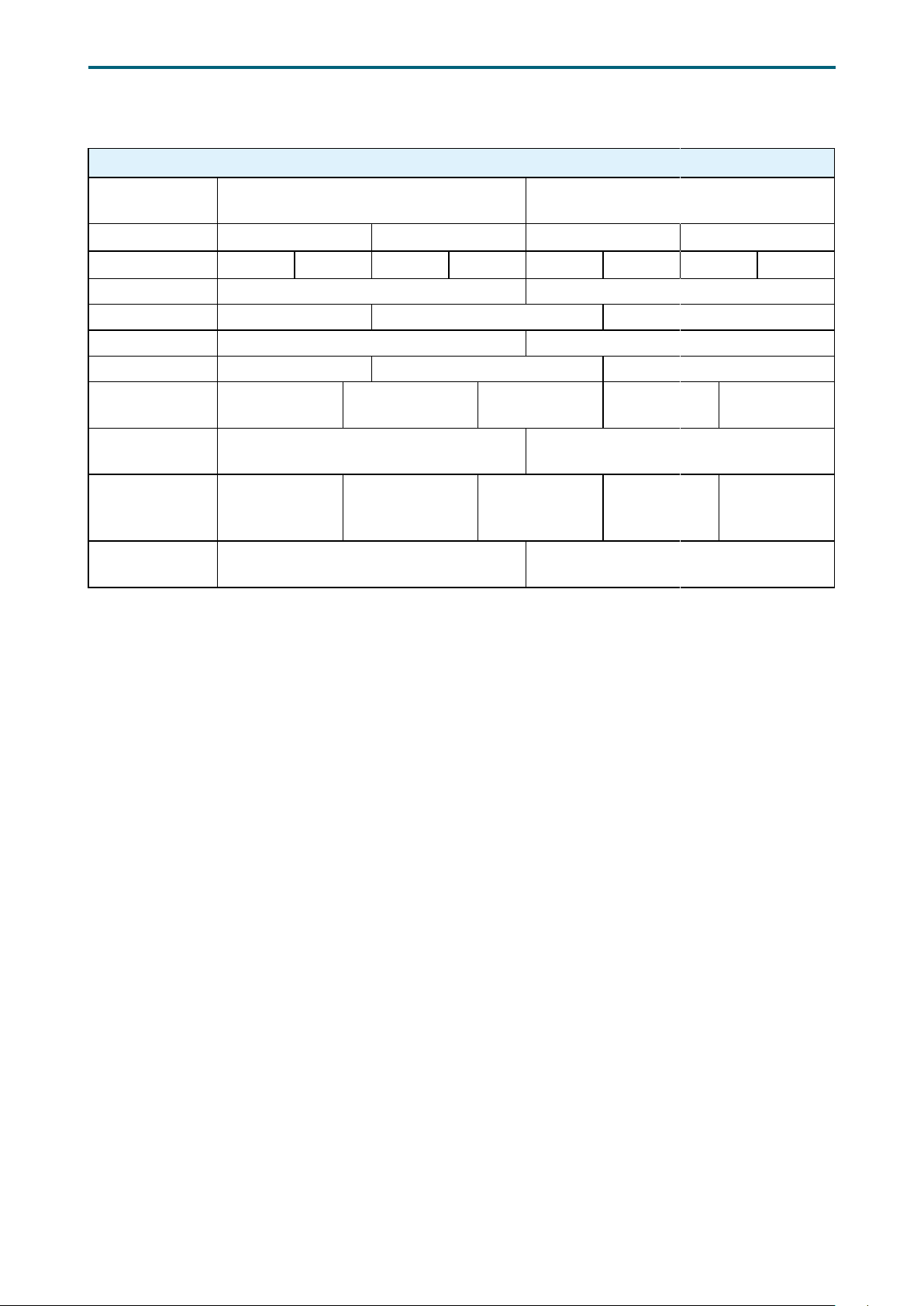
4�4�14 Console
Redirection Setup
Chapter 4. BIOS Conguration SettingsLynx User Manual
Console Redirection Setup
Console Serial
Redirect
Terminal Type VT_100 VT_100+ VT_UTF8 PC_ANSI
Baud Rate 1200 2400 4800 9600 19200 38400 57600 115200
Data Bits 7 Bits 8 Bits
Parity Even Odd None
Stop Bits 1 Bits 2 Bits
Flow Control RTS/CTS XON/XOFF None,
Information
Wait Time
C.R. After
Legacy Boot
Text Mode
Resolution
Use Global
Setting
Enable Disable
0 second 2 seconds 5 seconds 10 seconds 30 seconds
Yes No
Force 80x24
Auto Force 80x25
Enable Disable
(DEL FIRST
ROW)
Force 80x24
(DEL LAST
ROW)
Limit 128x40
59
Page 68
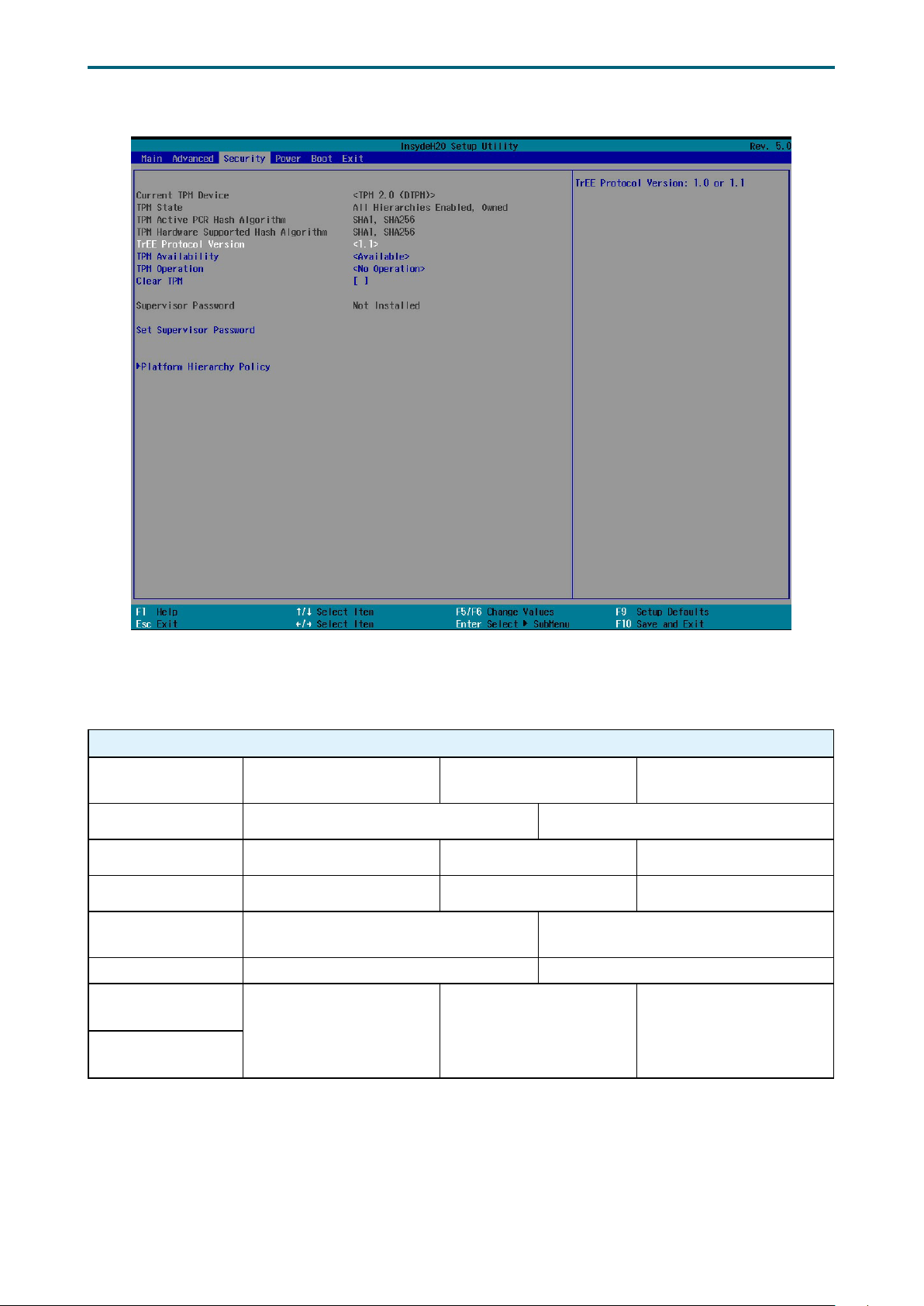
4�5 Security
Chapter 4. BIOS Conguration SettingsLynx User Manual
Security Option Key:
4�5�1 Security
Security
Current TPM
Device
TPM Availability Available Hidden
TPM Operation No operation Disable and Deactivate Enable and Activate
Clear TPM 0 1 None
TrEE Protocol
Version
TPM Availability Available Hidden
PCR Bank: SHA1
PCR Bank: SHA256
Not Detected TPM 1.2 TPM 2.0
1.0 1.1
0 1 None
60
Page 69
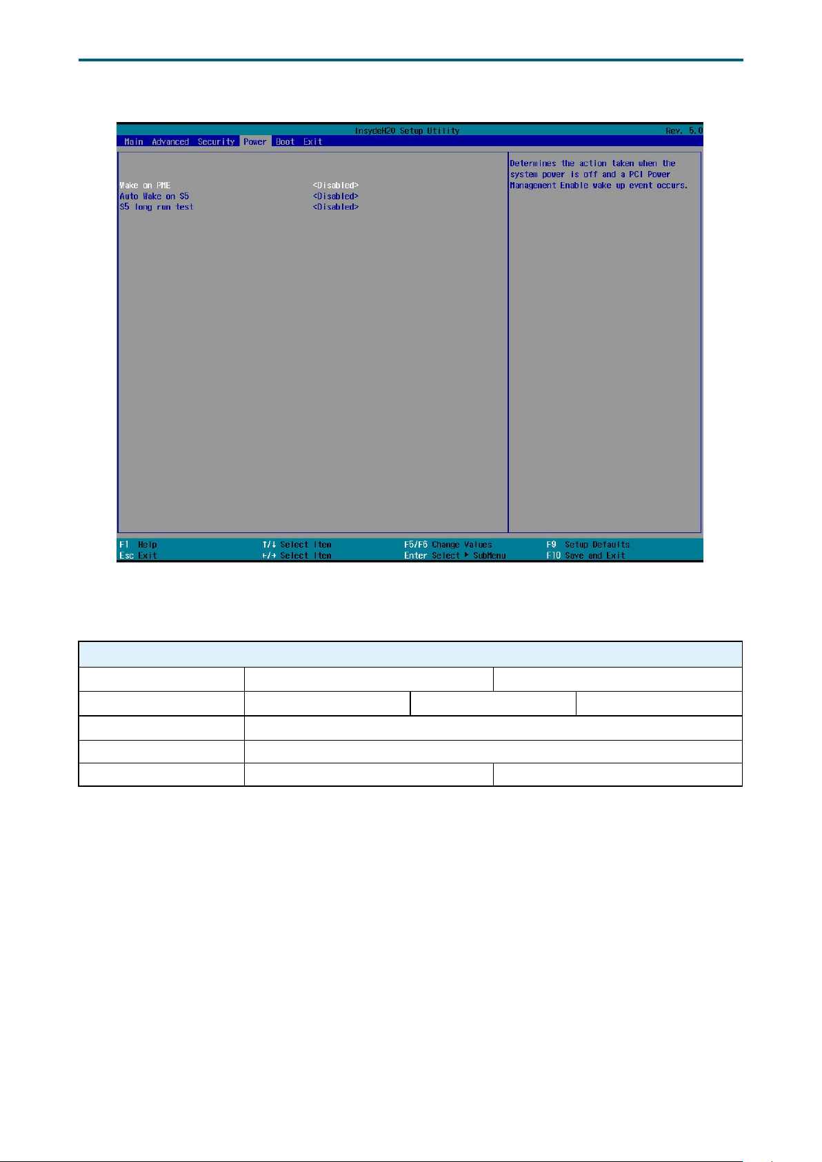
4�6 Power
Chapter 4. BIOS Conguration SettingsLynx User Manual
Power Option Key:
4�6�1 Power
Power
Wake on PME Enable Disable
Auto Wake on S5 By Every day By Day of Month Disable
Wake on S5 Time HH(0):MM(0):SS(0)
Day of Month Min=1, Max=31
S5 long run test Enable Disable
61
Page 70
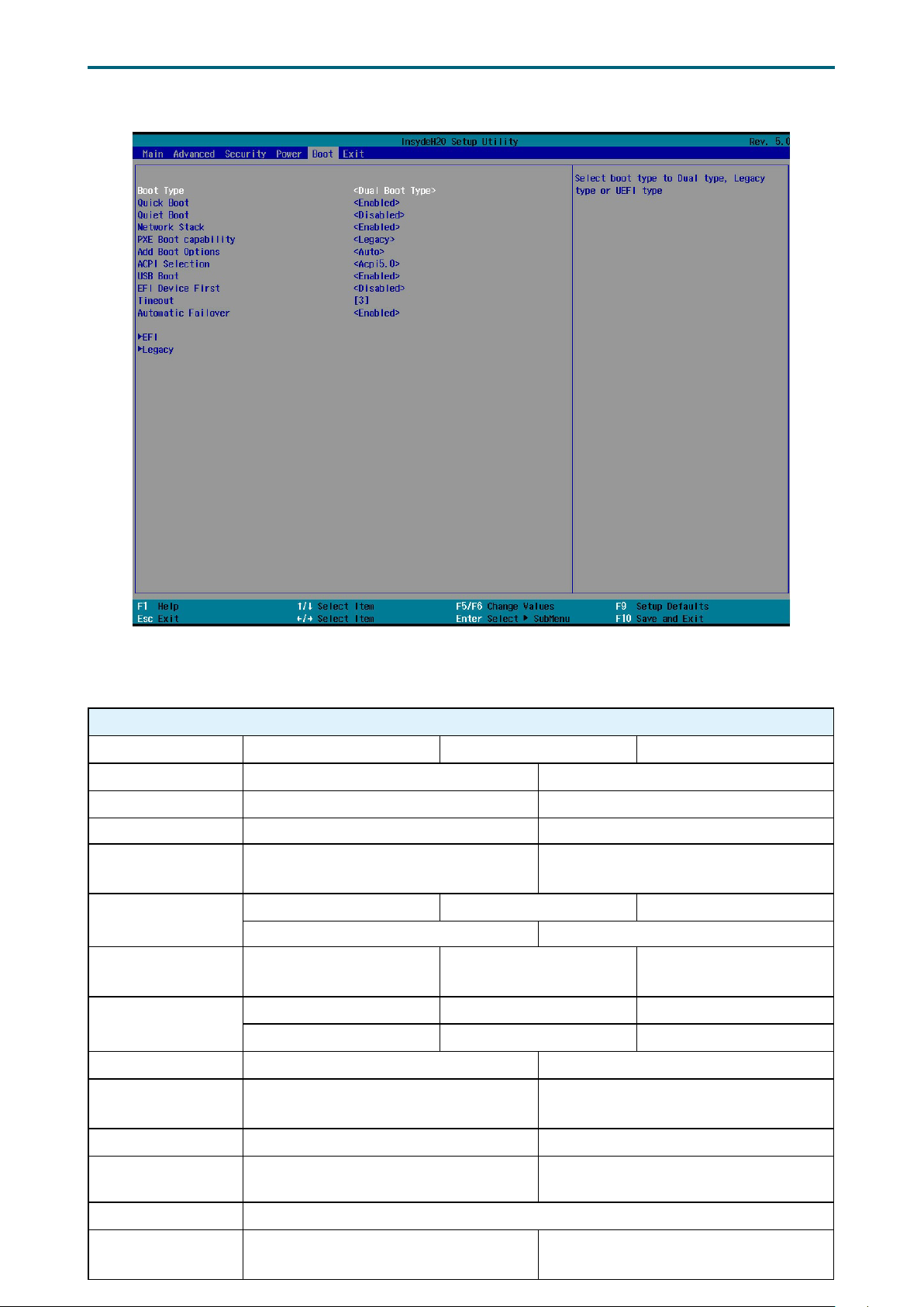
4�7 Boot
Chapter 4. BIOS Conguration SettingsLynx User Manual
Boot Option Key:
4�7�1 Boot
Boot
Boot Type Dual Boot Type Legacy Boot Type UEFI Boot Type
Quick Boot Enable Disable
Quiet Boot Enable Disable
Network Stack Enable Disable
PXE Boot to LAN Enable Disable
PXE Boot capability
Add Boot Options First Last Auto
ACPI Selection
USB Boot Enable Disable
Disable UEFI:IPv4 UEFI:IPv6
UEFI:IPv4/UEFI:IPv6 Legacy
Acpi1.0B Acpi3.0 Acpi4.0
Acpi5.0 Acpi6.0 Acpi6.1
EFI Device First Enable Disable
UEFI OS Fast Boot Enable Disable
USB Hot Key
Support
Timeout Min=0, Max=10
Automatic Failover Enable Disable
Enable Disable
62
Page 71
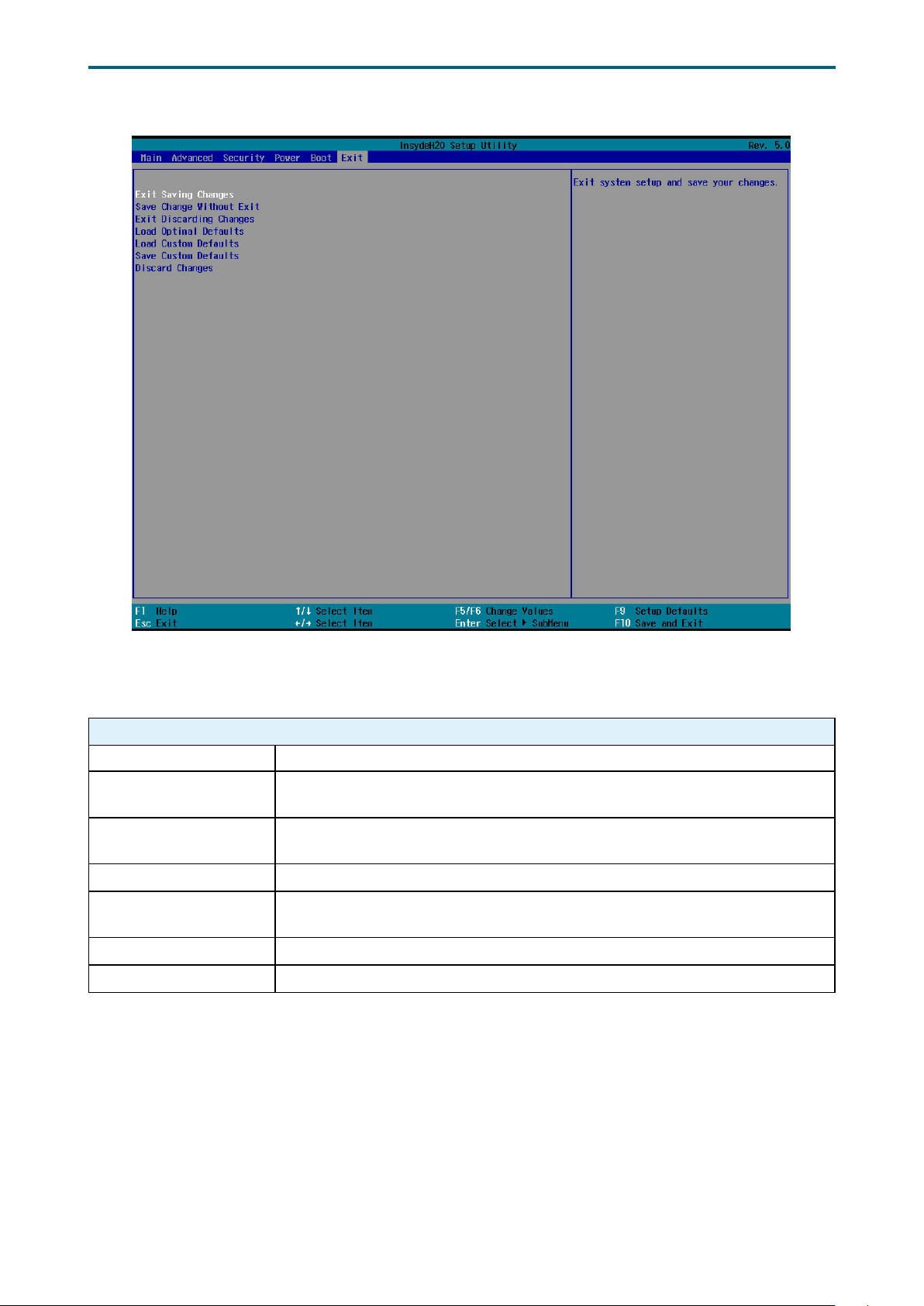
4�8 Exit
Chapter 4. BIOS Conguration SettingsLynx User Manual
Exit Option Key:
4�8�1 Exit
Save and Exit
Exit Saving Changes Exit system setup and save your changes.
Save Change Without
Exit
Exit Discarding
Changes
Load Optimal Defaults Load optimal default items.
Load Custom Defaults
Save Custom Defaults Saves the cumostomized defaults in BIOS settings.
Discard Changes Discard your changes.
Save your changes without exiting the system.
Discard your changes when existing the system.
Resets the BIOS settings to the default values and overwrites any
previously customized settings.
63
Page 72
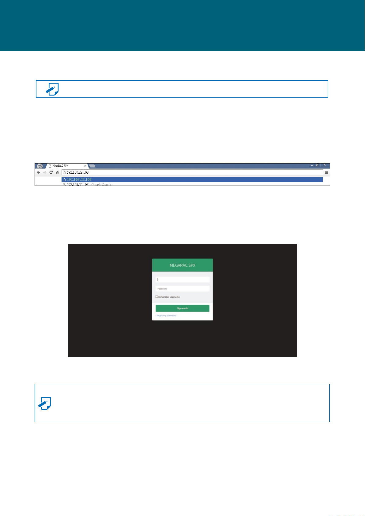
Chapter 5. BMC Conguration SettingsLynx User Manual
Chapter 5. BMC Conguration Settings
5�1 Login
NOTE This feature works with the JAVA 6 run time installed console environment.
The IP address below is an example using the default IP setting. The IP address is
congurable.
Step 1 Open the browser then type in the default BMC IP address: 192.168.22.108
Step 2 Use the default user name and password for rst-time BMC WEB GUI login.
Field: Default
UserName: admin
Password: admin
NOTE
The default user name and password are in lower-case characters.
Users who login with the root user name and password will have full administrative power.
The root password can be changed after login.
64
Page 73

5�2 Web GUI
5�2�1 Menu Bar
Click to select the options of the menu bar.
Menu Description
Chapter 5. BMC Conguration SettingsLynx User Manual
Dashboard
Sensor The Sensor Readings page displays all the sensor related information.
FRU Information The FRU Information page displays the details for FRU devices in the system.
Logs and Reports The Logs and Reports page monitors and reports on the status of IPMI event.
Settings
Remote Control
Image Redirection
Power Control
Maintenance This group of pages allows you to do maintenance tasks on the device.
Sign out The Sign out page allows you to log out of the web GUI.
The Dashboard page gives the overall information about the status of a
device.
The Settings page allows you to congure various basic settings, such as
date & time, KMV Mouse, Services, and ect.
The Remote Control page allows you to remotely manage server hardware
components.
The Image Redirection page is used to congure the image into BMC for
redirection.
The Power Control page allows you to view and control the power of your
server.
65
Page 74
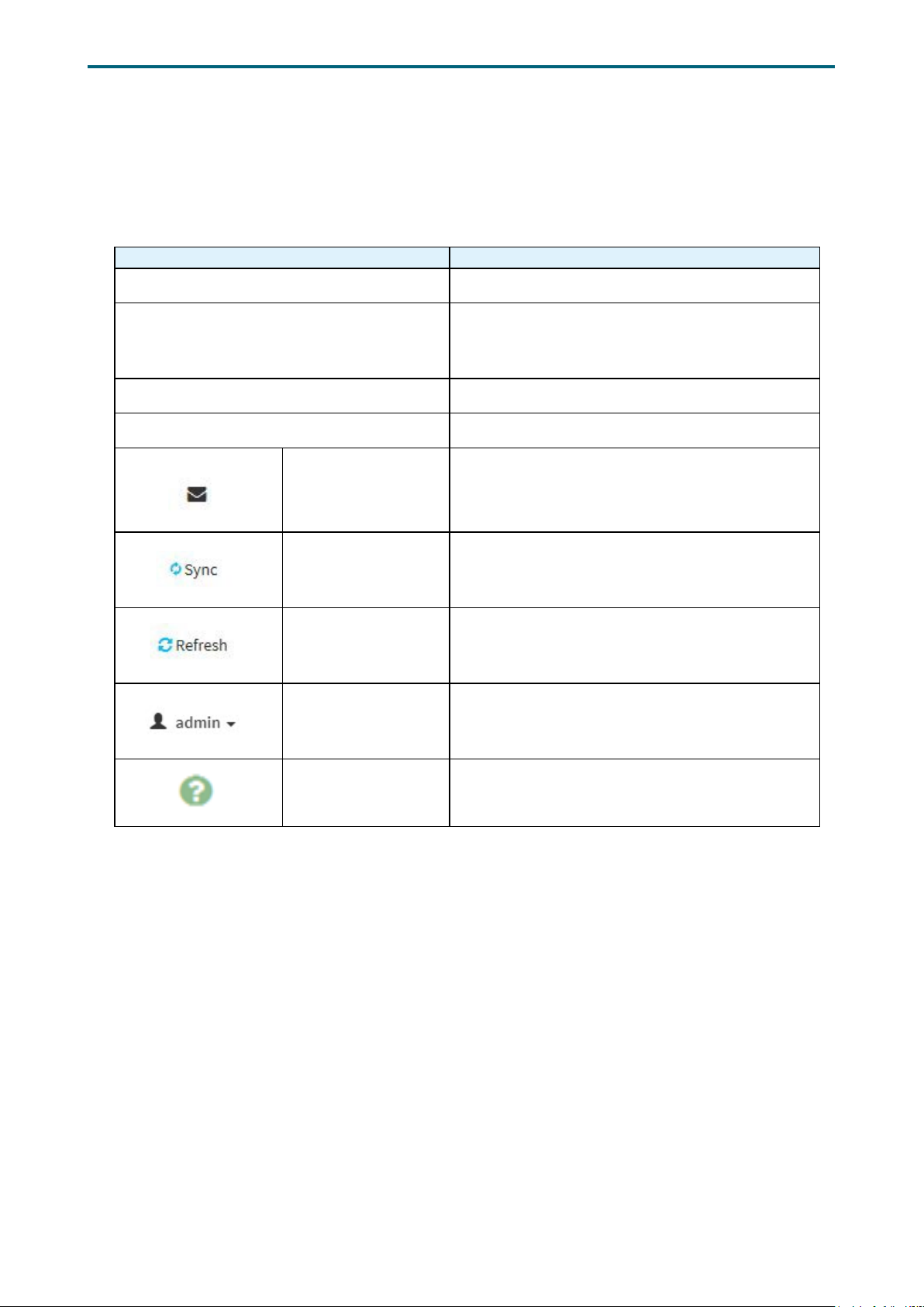
Chapter 5. BMC Conguration SettingsLynx User Manual
5�2�2 User Information and Quick Button
The user information and quick access buttons are located at the top right corner. It
displays the logged-in user, his/her privilege and the four quick buttons allowing you to
perform different functions.
Button Description
User Only valid commands are allowed.
Operator All BMC commands are allowed except for the
conguration commands that can change the
behavior of the out-of-hand interfaces.
Administrator All BMC commands are allowed.
No access Login access denied.
Notification Click to view notication messages.
Sync
Refresh Click to reload the current page.
Administrator
Help Click to view more details on eld descriptions.
Click to synchronize with the latest sensor and
event log updates.
Sign out: Click to log out of the GUI
Prole: Click to enter the User Management
Conguration dialog box in gure xx.
66
Page 75
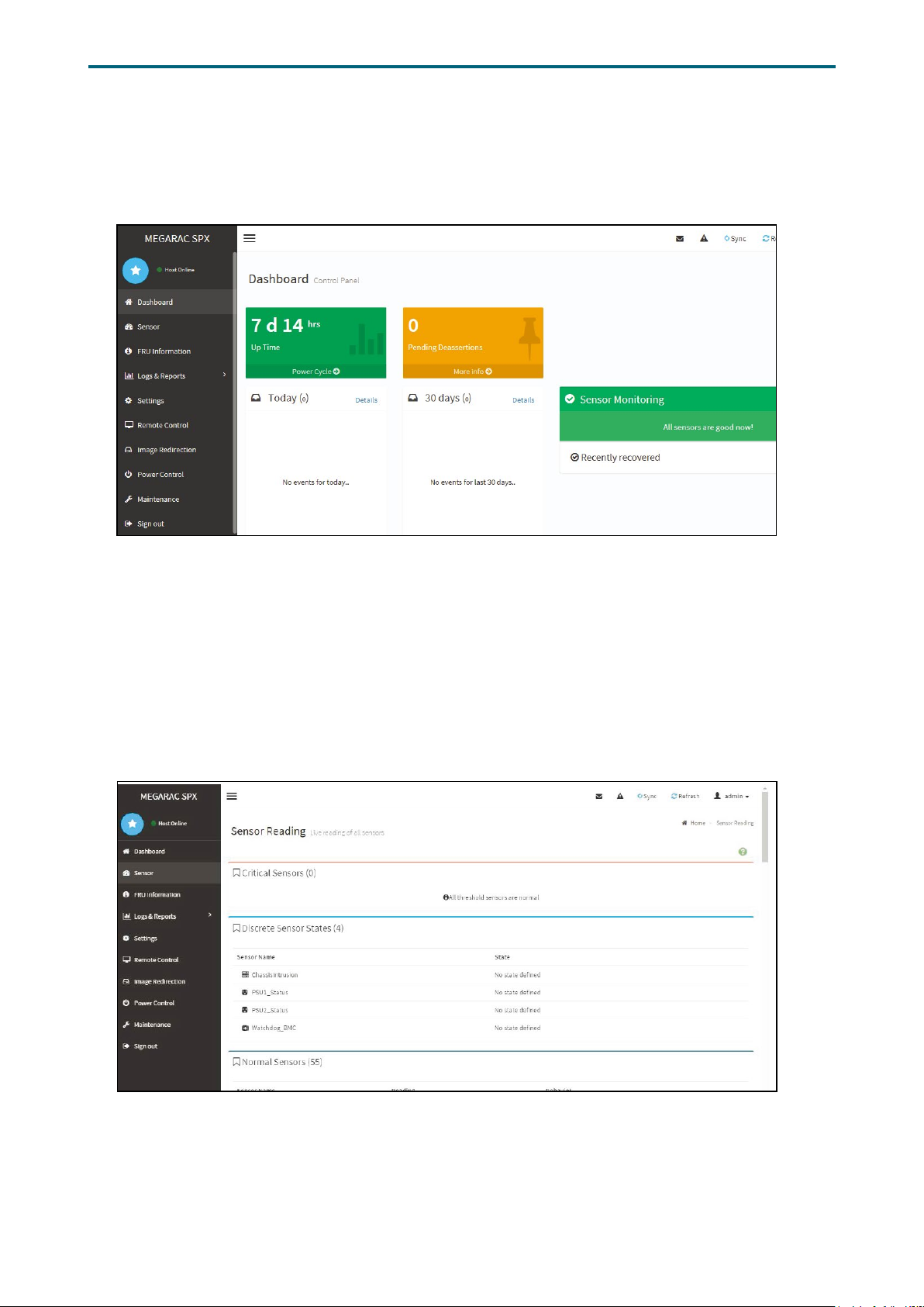
Chapter 5. BMC Conguration SettingsLynx User Manual
5�2�3 Dashboard
The Dashboord page displays device, system, and network information.
Click Dashboard on the menu bar to view the overall information of the server.
5�2�4 Sensor
The Sensor page displays the status and records on related sensors.
Click a record to view detailed information on a particular sensor.
67
Page 76
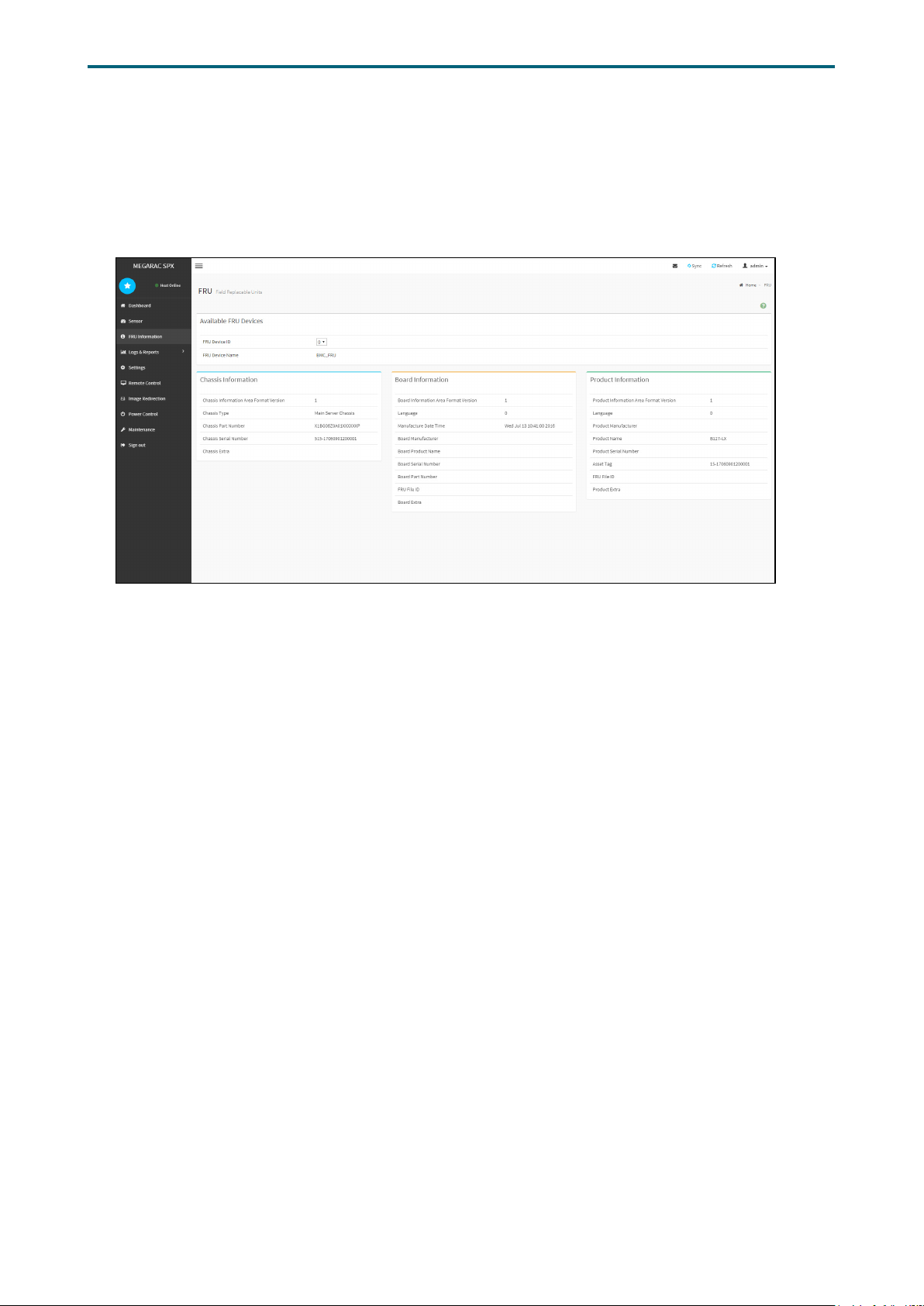
Chapter 5. BMC Conguration SettingsLynx User Manual
5�2�5 FRU Information
The FRU Information page displays Basic Information, Chassis Information, Board
Information and Product Information of the FRU device. Click FRU Information on the
menu bar to view the details of the selected device.
68
Page 77
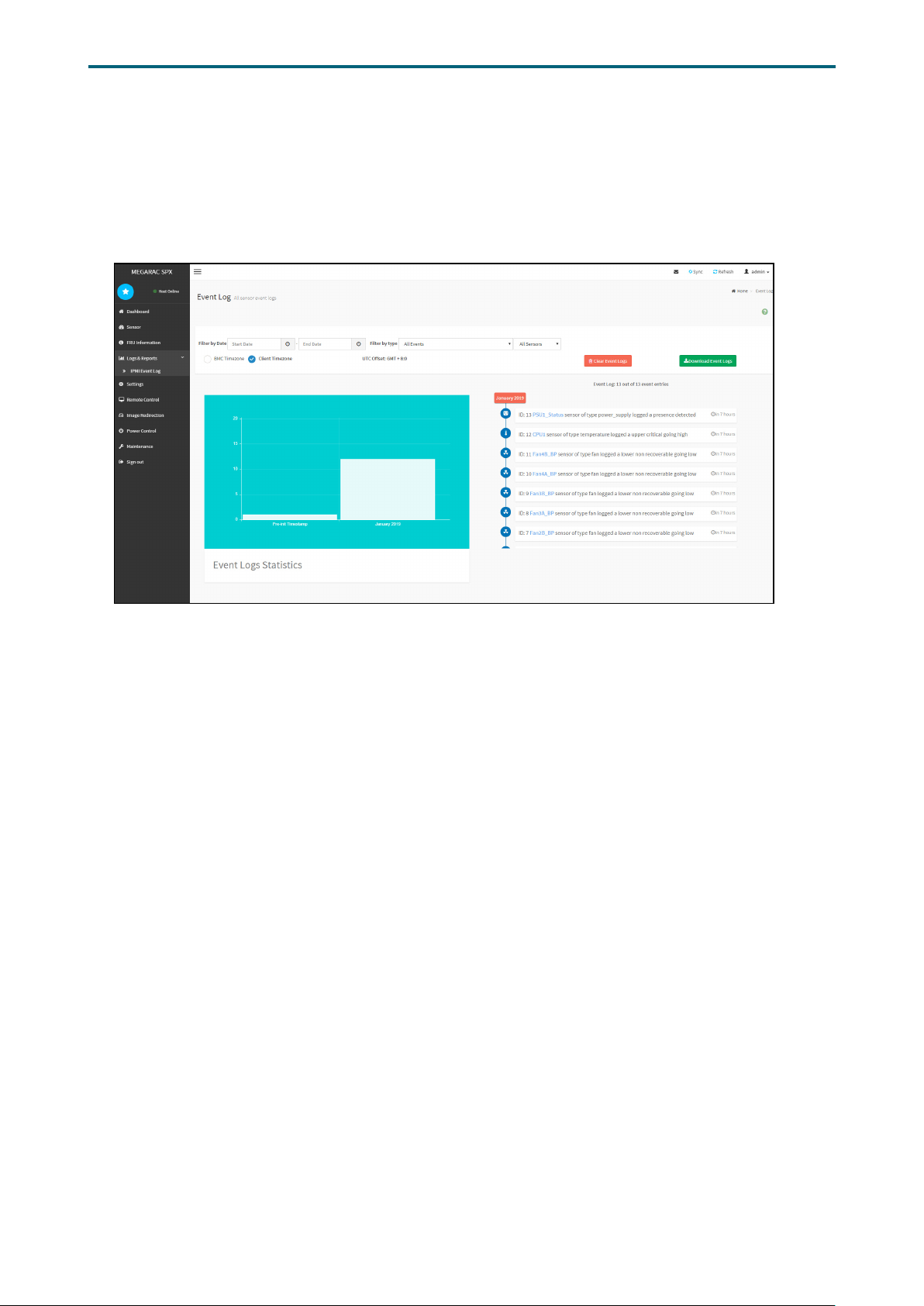
Chapter 5. BMC Conguration SettingsLynx User Manual
5�2�6 Logs and Reports The System Inventory page displays IPMI Event Log and Video Log. Click Logs and
Reports from the menu bar→ select Event Log or Video Log to view the contents.
Event Log
69
Page 78
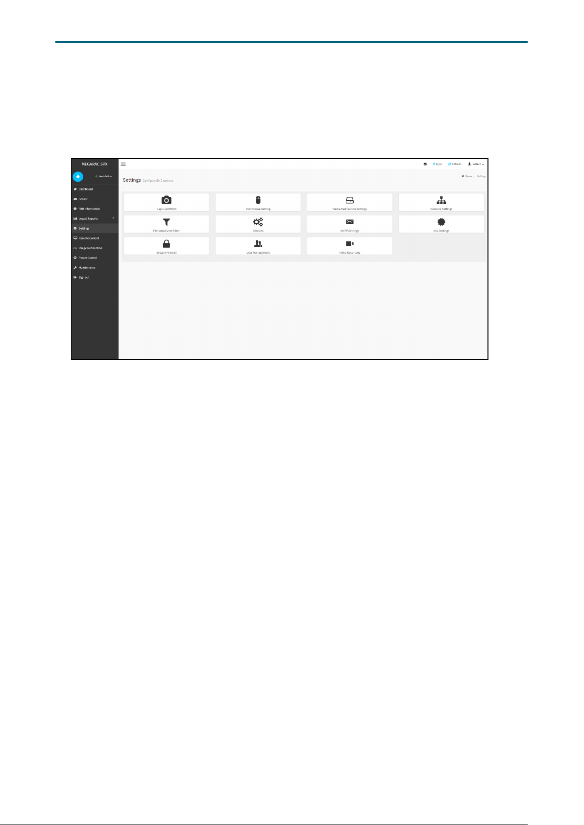
Chapter 5. BMC Conguration SettingsLynx User Manual
5�2�7 Settings
The Settings page displays the conguration settings for KVM Mouse Setting, Media
Redirection Settings, Network Settings, Platform Event Filter, Services, SMTP Settings,
SSL Settings, System Firewall, User Management, and Video Recording.
70
Page 79
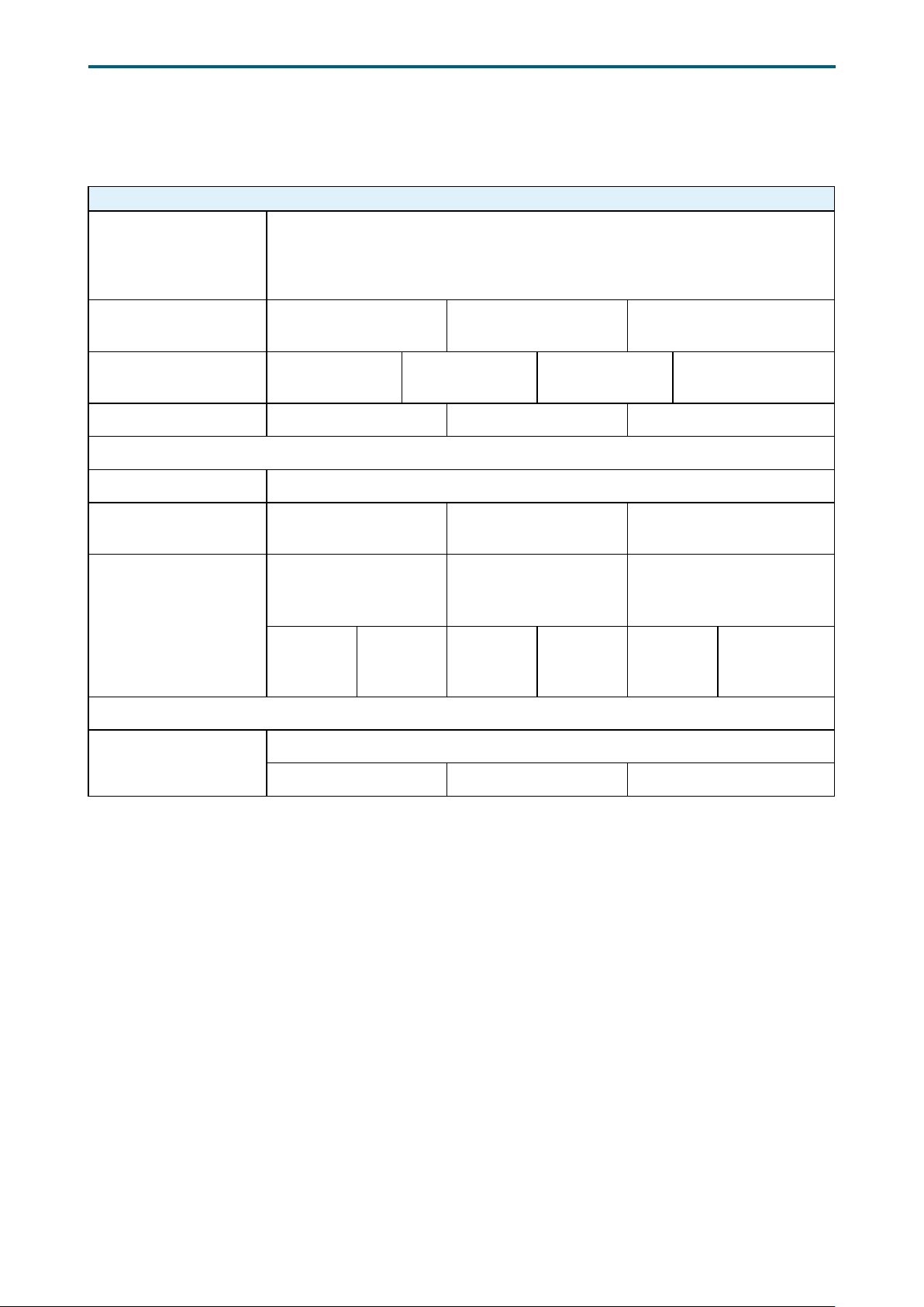
Settings Menu and Option Keys:
Settings
Mouse Mode Conguration
KVM Mouse Setting
• Relative Positioning (Linux)
• Absolute Positioning (Windows)
• Other Mode (SLES-11 OS Installation)
Chapter 5. BMC Conguration SettingsLynx User Manual
Media Redirection
Settings
Network Settings Network Settings
Platform Event Filter Event Filters Alert Policies LAN Destinations
Services
SMTP Settings SMTP Settings
SSL Settings View SSL certicate
System Firewall
User Management
Video Recording
General Settings
Generate Firewall
Settings
Existing
Firewall
Settings
Auto Video Settings
Video Trigger Settings Video Remote Settings Pre-Event Video Recordings
Add
Firewall
Settings
VMedia Instance
Settings
Network Link
Conguration
Generate SSL
certicate
IP Address Firewall
Rules
Existing IP
Rules
DNS
Conguration
Add New
IP rule
Remote Session
Sideband Interface
(NC-SI)
Upload SSL certicate
Port Firewall Rules
Existing
Port Rules
Add New Port
Rule
71
Page 80
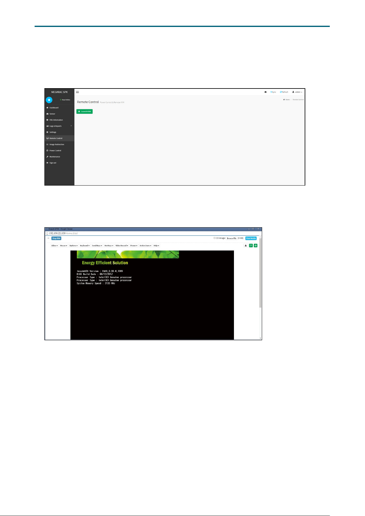
Chapter 5. BMC Conguration SettingsLynx User Manual
5�2�8 Remote Control
The Remote Control page displays the conguration for power control and remote KVM.
Launch KVM
72
Page 81
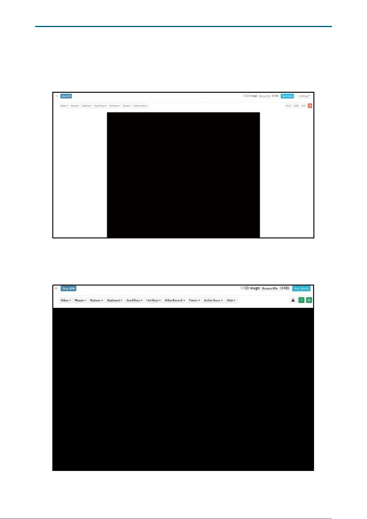
Chapter 5. BMC Conguration SettingsLynx User Manual
Procedure To Start KVM
Step 1 Click Start KVM to start the H5Viewer video redirection.
Step 2 Click Browse to select CD Image.
Step 3 Click Start Media to redirect the selected CD image le to the Host.
Step 4 To stop the recording, click Stop Record.
73
Page 82
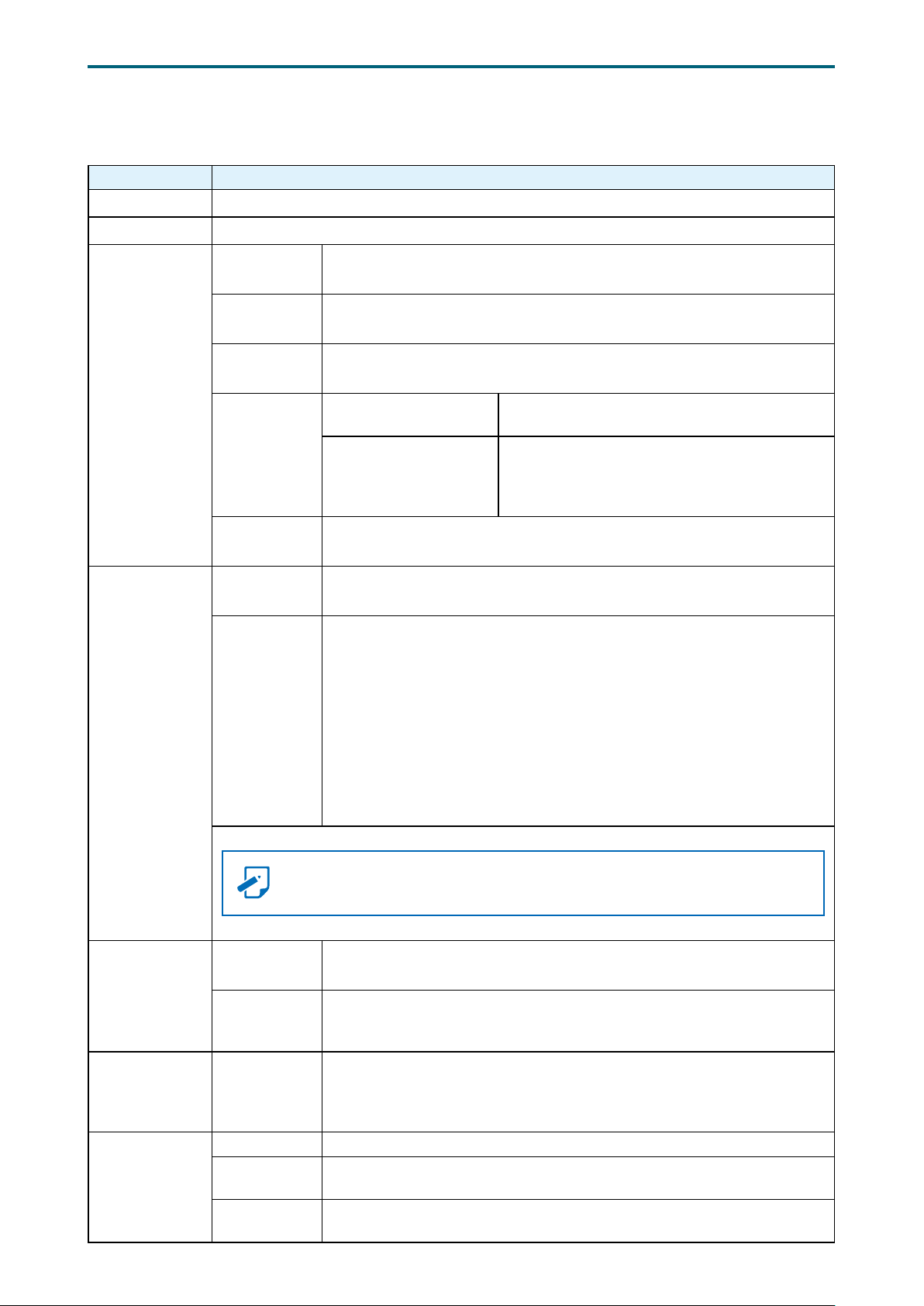
Remote KVM Menu and Option Key
Button Description
Start KVM Starts the H5Viewer video redirection.
Stop KVM Stops the H5Viewer video redirection.
Pause Video This option is used for pausing Console Redirection.
Chapter 5. BMC Conguration SettingsLynx User Manual
Video Record
Mouse
Resume Video
Refresh Video
Host Display
Capture
Screen
Show Client
Cursor
Mouse Mode
This option is used to resume the Console Redirection when the session
is paused.
This option can be sued to update the display shown in the Console
Redirection window.
Display on
Display off
This option helps to take the screenshot of the host screen and save it in
the client’s system.
This menu item can be used to show or hide the local mouse cursor on
the remote client system.
This option handles mouse emulation from local window to remote
screen using either of the two methods. Only ‘Administrator’ has the right
to congure this option.
• Absolute mouse mode: The absolute position of the local mouse is
sent to the server if this option is selected.
• Relative mouse mode: The Relative mode sents the calculated
relative mouse potion displacement to the server if this option is
selected.
• Other mouse mode: This mouse mode sets the client cursor in the
middle of the client system and will send the deviation to the host.
This mouse mode is specic for SUSE Linux installation.
If you disable this option, the display will be
shown on the screen in Console Redirection.
If you enable this option, the server display
will be blank but you can view the screen in
Console Redirection. If you disable this option,
the display will be back in the server screen.
Options
Keyboard
Video Record
NOTE
Alt + C to access the menu.
Block Privilege
Request
Keyboard/
Mouse
Encryption
Keyboard
Layout
Record Video This option is to start recording the screen.
Stop
Recording
Record
Settings
Client cursor will be hidden always. If you want to enable, use
To enable or disable the access privilege of the user.
This option allows you to encrypt keyboard inputs and mouse movements
sent between the connections
List of Host Physical Keyboard languages supported in H5Viewer.
1. English US
2. German
3. Japanese
This option is used to stop the recording.
This option is used to set Video Recording Duration.
74
Page 83

Chapter 5. BMC Conguration SettingsLynx User Manual
Right <Ctrl>
Right <Alt>
Right <Window>
Hold Down
Send Keys
Press and
Release
Hot Keys Add Hot Keys This menu is used to enable macros. Click Add to macros.
Power Reset To reboot the system without powering off (warm boot).
Immediate
Shutdown
Power
Active Users Read only. Displays active user and their system IP address.
Help Read only. Displays information about H5viewer
Orderly
Shutdown
Power On To power on the server.
Power Cycle To rst power off, and then reboot the system (cold boot).
Left <Ctrl>
Left <Alt>
Left <Window>
<Ctrl> + <Alt> + <Del>
Left <Windows>
Right <Windows>
<Context Menu>
<Print Screen>
Power Off the server immediately.
Soft power off.
This menu item can be used to act as the rightside <CTRL> key when in Console Redirection.
This menu item can be used to act as the rightside <ALT> key when in Console Redirection.
This menu item can be used to act as the rightside <WIN> key when in Console Redirection.
This menu item can be used to act as the left-
side <CTRL> key when in Console Redirection.
This menu item can be used to act as the left-
side <ALT> key when in Console Redirection.
This menu item can be used to act as the left-
side <WIN> key when in Console Redirection.
You can also decide how the key should be
pressed: Hold Down or Press and Release.
This menu item can be used to act as if you
depressed the <CTRL>, <ALT> and <DEL> keys
down simultaneously on the server that you
are redirecting.
This menu item can be used to act as the left-
side <WIN> key when in Console Redirection.
You can also decide how they key should be
pressed: Hold Down or Press and Release.
This menu item can be used to act as the rightside <WIN> key when in Console Redirection.
This menu item can be used to act as
the context menu key, when in Console
Redirection.
This menu item can be used to act as the print
screen key, when in Console Redirection.
75
Page 84
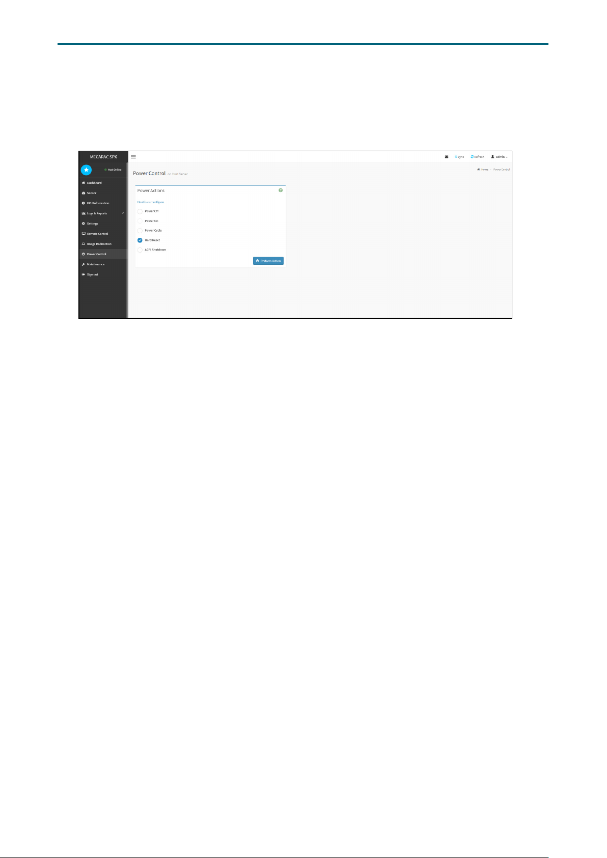
Chapter 5. BMC Conguration SettingsLynx User Manual
5�2�9 Power Control
The Power Control page allows you to view and control the power of your server.
To open Power Control, click Power Control from the menu bar.
The various options of Power Control are given below.
Power Off: To immediately power off the server.
Power On: To power on the server.
Power Cycle: This option will rst power off, and then reboot the system (cold boot).
Hard Reset: This option will reboot the system without powering off (warm boot).
ACPI Shutdown: This option to initiate operating system shutdown prior to the
shutdown.
Perform Action: Click this option to perform the selected operation.
76
Page 85
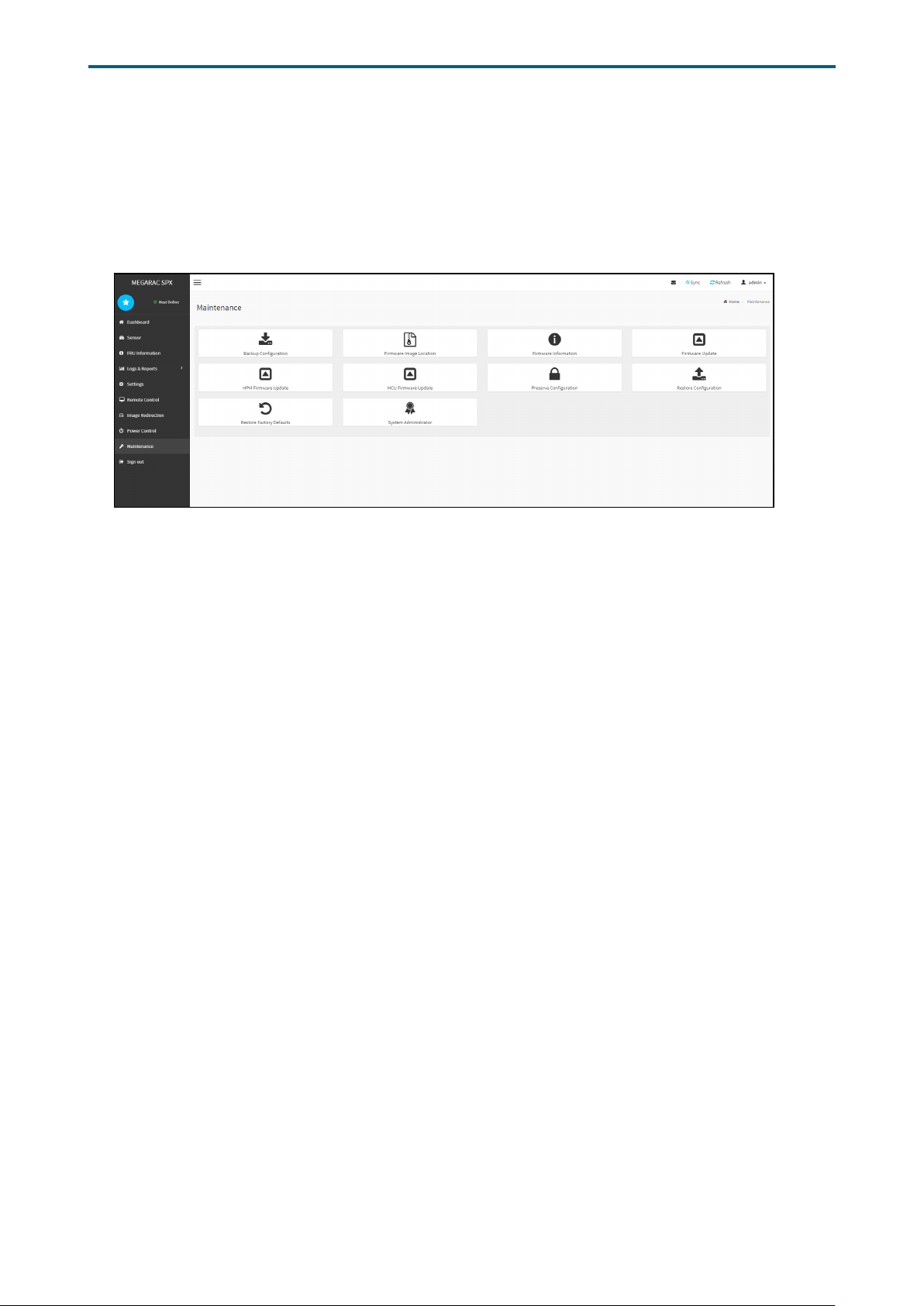
Chapter 5. BMC Conguration SettingsLynx User Manual
5�2�10 Maintenance
This Maintenance page displays the conguration settings for Backup Conguration,
Firmware Image Location, Firmware Information, Fimware Update, Preserve
Configuration, Restore Configuration, Restore Configuration, and Restore Factory
Defaults.
77
Page 86

Maintenance Procedure
1. Click Check All to backup the selected conguration items. The Backup
Conguration page will appear Click Download Cong to save the backup
Backup Conguration
le to the client system
2. Click OK to perform the backup action. The Backup le will be saved in the
client system.
3. Click Cancel to cancel the backup process.
Chapter 5. BMC Conguration SettingsLynx User Manual
Firmware Image
Location
Firmware Information Read only.
Firmware Update
Preserve Conguration
Restore Conguration
Restore Factory
Defaults
1. Click the conguration items on the list.
2. Click Save to save any changes made.
This wizard takes you through the process of firmware upgradation. A reset
of the box will automatically follow if the upgrade is completed or cancelled.
An option to Preserve All Configuration is available. Enable it, if you wish to
preserver congured settings through the upgrade.
Click Start Firmware Update to start the rmware update process.
This page allows the user to configure the preserve configuration items,
which will be used by the Restore factory defaults to preserve the existing
conguration without overwriting with defaults/Firmware Upgrade conguration.
Click Save to save any changes made.
1. Click Upload to restore the backup les.
2. Click OK to upload the new conguration le and restore.
1. Click the conguration items on the list to preserve the settings during
restore factory default conguration.
2. Click Restore Factory Defaults to restore the factory defaults of the device
rmware.
78
Page 87
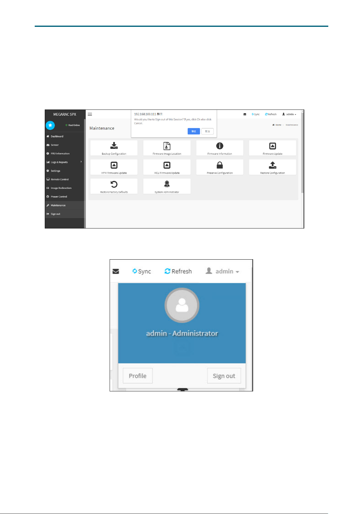
Chapter 5. BMC Conguration SettingsLynx User Manual
5�2�11 Sign out
To log out of the BMC:
Method 1: Click Sign out from the menu bar. The Logout dialog box will pop out.
Method 2: Click the root quick button on the top right corner of the screen.
79
Page 88

Chapter 5. BMC Conguration SettingsLynx User Manual
5�3 Firmware Update
1. Boot to the DOS (MS-DOS or Free DOS is workable).
2. Enter BMC rmware directory [XXXXXLXOOOYYY_ARK];
XXXXX: project name ;
OOO: for Lynx standard version
YYY:rmware version;
K: For auxiliary version
3. Execute a�bat batch le to update the BMC rmware.
Example:
A:>cd FB201LX010003_AR1
A:\ FB201LX010003_AR1>a.bat
This is just an example. The latest BMC rmware version is available from the
FAE or AIC website.
4. After updating the BMC rmware, please turn off and then turn on the system.
80
Page 89

Chapter 6� Technical Support
Taiwain, Global Headquarters
Address: No. 152, Section 4,
Linghang N� Rd, Dayuan District,
Taoyuan City 337, Taiwan
Tel: +886-3-433-9188
Fax: +886-3-287-1818
Sales Email: sales@aicipc�com�tw
Support Email: [email protected]
Shanghai, China
Address: Room 1009, No. 777,
Zhaojia Bang Rd, Shanghai 200032,
Shanghai, China
Tel: +86-21-54961421
Fax +86-21-54961422 #608
Sales Email: [email protected]
Support Email: [email protected]
Moscow, Russia
Address: Khoroshevskoye Shosse, 32A,
Office 403 (2nd Entrance, 4th Floor),
Moscow 123007, Russia
Tel: +7-4997019998
Sales Email: [email protected]
Support Email: [email protected]
South California, United States
Address: 21808 Garcia Lane
City of Industry, CA 91789,
United States
Toll free: +7-4997019998
Tel: +1-909-895-8989
Fax: +1-909-895-8989#157
Sales Email: [email protected]
Support Email: [email protected]
New Jersey, United States
Address: 11 Melanie Lane
Unit #20 & 21
East Hanover, NJ 07936, United States
Tel: +1-973-884-8886
Fax: +1-973-884-4794
Sales Email: [email protected]
Support Email: [email protected]
Houten, The Netherlands
Address: Peppelkade 58, 3992AK, Houten,
The Netherlands
Tel: +31-30-6386789
Fax: +31-30-6360638
Sales Email: [email protected]
Support Email: [email protected]
North California, United States
Address: 48531 Warm Springs
Boulvard Suite 404 Fremont, CA
94539, United States
Tel: +1-510-573-6730
Fax: +1-510-573-6729
Sales Email: [email protected]
Support Email: [email protected]
 Loading...