

AHRI Ultra Low NOX Residential Gas Water Heaters Instruction Manual
Instruction Manual
ULTRA LOW NOX RESIDENTIAL GAS WATER HEATERS
NOT FOR USE IN MANUFACTURED (MOBILE) HOMES
LOW LEAD
CONTENT
• For Your Safety •
AN ODORANT IS ADDED TO THE GAS USED
BY THIS WATER HEATER.
ALL TECHNICAL AND WARRANTY QUESTIONS: SHOULD BE DIRECTED TO THE LOCAL DEALER FROM WHOM THE WATER HEATER WAS
PURCHASED. IF YOU ARE UNSUCCESSFUL, PLEASE WRITE TO THE COMPANY LISTED ON THE RATING PLATE ON THE WATER HEATER.
KEEP THIS MANUAL IN THE POCKET ON HEATER FOR FUTURE REFERENCE
PRINTED 0115 324257-001
WHENEVER MAINTENANCE ADJUSTMENT OR SERVICE IS REQUIRED.
1

TABLE OF CONTENTS
SAFE INSTALLATION, USE AND SERVICE............................3
GENERAL SAFETY INFORMATION ........................................ 4
Abbreviations Used.................................................................5
Qualied Installer or Service Agency ......................................5
Preparing For The Installation ................................................5
INTRODUCTION ...................................................................... 5
INSTALLATION CONSIDERATIONS .......................................6
Thermometers (Not Supplied) ................................................7
Facts to Consider About the Location .....................................7
High Altitude............................................................................8
Clearances..............................................................................8
Insulation Blankets..................................................................9
Hard Water .............................................................................9
Circulation Pumps...................................................................9
Gas Supply Systems ............................................................10
Gas Pressure Requirements ................................................10
Supply Gas Regulator...........................................................10
Mixing Valves ........................................................................10
INSTALLATION REQUIREMENTS ........................................10
Water Piping ......................................................................... 11
Closed Water Systems ......................................................... 11
Thermal Expansion ............................................................... 11
Temperature-Pressure Relief Valve ...................................... 11
Fresh Air Openings For Conned Spaces ............................13
Outdoor Air Through Two Openings .....................................13
Outdoor Air Through Two Horizontal Ducts ..........................14
Outdoor Air Through Two Vertical Ducts ............................... 14
Air From Other Indoor Spaces .............................................. 14
Venting ..................................................................................14
Gas Piping ............................................................................ 16
Sediment Traps.....................................................................17
TEMPERATURE REGULATION ............................................19
Start Up Conditions...............................................................19
Operational Conditions ......................................................... 20
Venting System Inspection ...................................................21
Burner Inspection..................................................................21
Burner Cleaning .................................................................... 21
Housekeeping ....................................................................... 21
PERIODIC MAINTENANCE ................................................... 21
Anode Rod Inspection ..........................................................22
Temperature-Pressure Relief Valve Test .............................. 22
Draining And Flushing...........................................................23
Service .................................................................................. 23
REPLACING PARTS .............................................................. 24
Replacement Parts ............................................................... 24
Filling the Water Heater ........................................................12
Air Requirements .................................................................. 12
Unconned Space ................................................................13
Conned Space .................................................................... 13
LEAKAGE CHECKPOINTS .................................................... 27
REPAIR PARTS ......................................................................28
TROUBLESHOOTING GUIDELINES .....................................29
NOTES ...................................................................................30
2
SAFE INSTALLATION, USE AND SERVICE
Low Lead Content
The proper installation, use and servicing of this water heater is extremely important to your safety and the safety of others.
Many safety-related messages and instructions have been provided in this manual and on your own water heater to warn you and
others of a potential injury hazard. Read and obey all safety messages and instructions throughout this manual. It is very important
that the meaning of each safety message is understood by you and others who install, use, or service this water heater.
This is the safety alert symbol. It is used to alert you to
potential personal injury hazards. Obey all safety
messages that follow this symbol to avoid possible
injury or death.
DANGER indicates an imminently
DANGER
WARNING
CAUTION
hazardous situation which, if not avoided,
will result in injury or death.
WARNING indicates a potentially hazardous
situation which, if not avoided, could result
in injury or death.
CAUTION indicates a potentially hazardous
situation which, if not avoided, could result in
minor or moderate injury.
CAUTION used without the safety alert
CAUTION
All safety messages will generally tell you about the type of hazard, what can happen if you do not follow the safety message, and
how to avoid the risk of injury.
The California Safe Drinking Water and Toxic Enforcement Act requires the Governor of California to publish a list of substances
known to the State of California to cause cancer, birth defects, or other reproductive harm, and requires businesses to warn of
potential exposure to such substances.
WARNING: This product contains a chemical known to the State of California to cause cancer, birth defects, or other reproductive
harm. This appliance can cause low level exposure to some of the substances listed in the Act.
symbol indicates a potentially hazardous
situation which, if not avoided, could result in
property damage.
APPROVALS
3
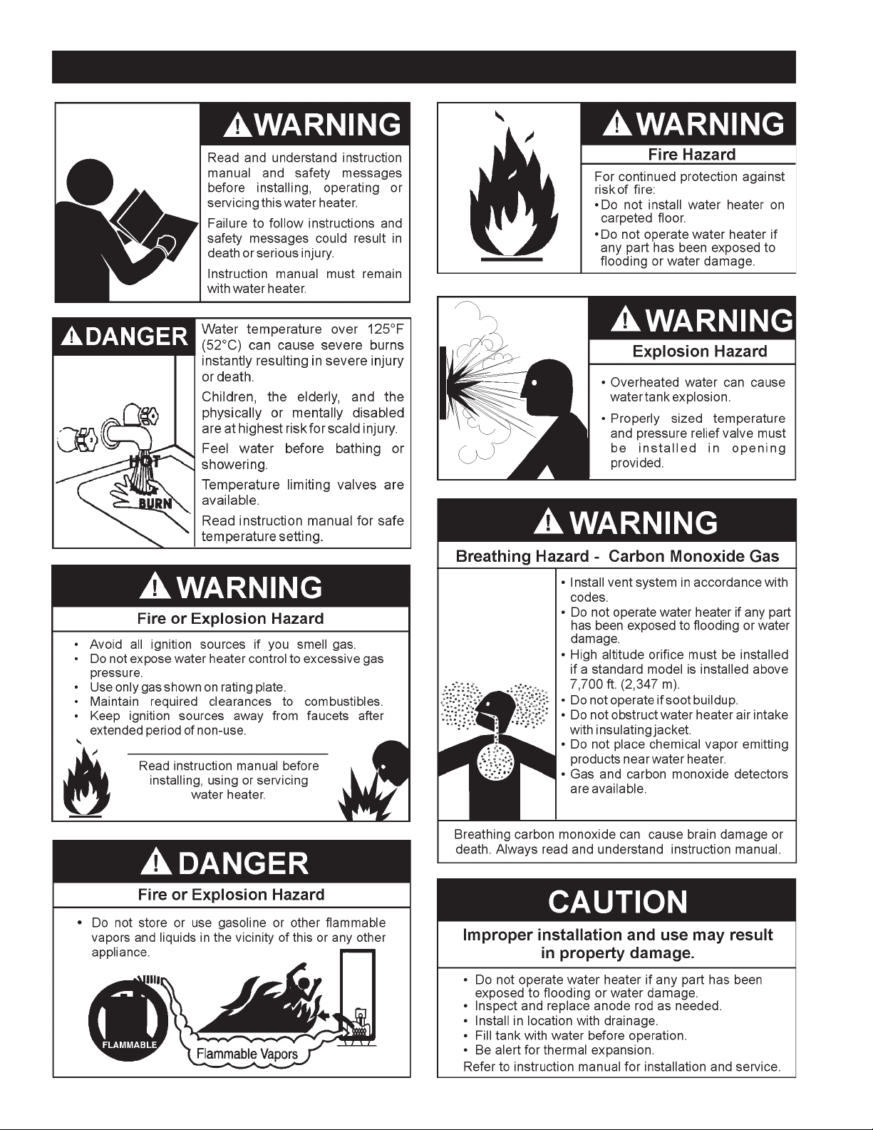
GENERAL SAFETY INFORMATION
4

INTRODUCTION
Thank You for purchasing this water heater. Properly installed and
maintained, it should give you years of trouble free service.
ABBREVIATIONS USED
Abbreviations Found In This Instruction Manual:
• UL - Underwriters Laboratories Inc.
• ANSI - American National Standards Institute
• NFPA - National Fire Protection Association
• ASME - American Society of Mechanical Engineers
• AHRI - Air-Conditioning, Heating and Refrigeration Institute
• EPACT - Energy Policy Act
• CSA - Canadian Standards Association
This gas-fired water heater is design certified by Underwriters
Laboratories Inc. under American National Standard/CSA Standard
for Gas Water Heaters ANSI Z21.10.3 • CSA 4.3 (current edition).
QUALIFIED INSTALLER OR SERVICE AGENCY
Installation and service of this water heater requires ability equivalent
to that of a Qualied Agency (as dened by ANSI below) in the eld
involved. Installation skills such as plumbing, air supply, venting,
gas supply and electrical supply are required in addition to electrical
testing skills when performing service.
ANSI Z223.1 2006 Sec. 3.3.83: “Qualied Agency” - “Any individual,
rm, corporation or company that either in person or through a
representative is engaged in and is responsible for (a) the installation,
testing or replacement of gas piping or (b) the connection, installation,
testing, repair or servicing of appliances and equipment; that is
experienced in such work; that is familiar with all precautions required;
and that has complied with all the requirements of the authority
having jurisdiction.”
If you are not qualied (as dened by ANSI above) and licensed or
certied as required by the authority having jurisdiction to perform a
given task do not attempt to perform any of the procedures described
in this manual. If you do not understand the instructions given in
this manual do not attempt to perform any procedures outlined in
this manual.
PREPARING FOR THE INSTALLATION
1. Read the General Safety Information section, page 4 of this
manual first and then the entire manual carefully. If you
don’t follow the safety rules, the water heater will not operate
pro p erly. It co uld cau s e DE AT H, SER I OUS BOD I LY INJUR Y
AND/OR PROPERTY DAMAGE.
This manual contains instructions for the installation,
operation, and maintenance of the gas-fired water heater.
It also contains warnings throughout the manual that you
must read and be aware of. All warnings and all instructions
are essential to the proper operation of the water heater
and your safety. Since we cannot put everything on the
first few pages, READ THE ENTIRE MANUAL BEFORE
ATTEMPTING TO INSTALL OR OPERATE THE WATER
HEAT ER.
2. The installation must conform with these instructions and
the local code authority having jurisdiction. In the absence
of local codes, the installation must comply with the current
edition of the National Fuel Gas Code, ANSI Z223.1/NFPA
54. All documents are available from the Canadian Standards
Association, 8501 East Pleasant Valley Road, Cleveland, OH
44131. NFPA documents are also available from the National
Fire Protection Association, 1 Batterymarch Park, Quincy,
MA 02269.
3. If after reading this manual you have any questions or do
not understand any por tion of the instructions, call the local
gas utility or the manufacturer whose name appears on the
rating plate.
4. Carefully plan the place where you are going to put the
water heater. Correct combustion, vent action, and vent
pipe installation are very impor tant in preventing death from
possible carbon monoxide poisoning and fires, see Figures
3 and 7.
Examine the location to ensur e the water heate r compli es wit h
the Fact to Consider About The Location section in this manual.
5. For California installation this water heater must be braced,
anchored, or strapped to avoid falling or moving during
an earthquake. See instructions for correct installation
procedures. Instructions may be obtained from California
Office of the State Architect, 400 P Street, Sacramento,
CA 95814.
6. Massachusetts Code requires this water heater to be installed
in accordance with Massachusetts 248-CMR 2.00: State
Plumbing Code and 248-CMR 5.00.
7. Complies with SCAQMD rule #1146.2 and districts having
equivalent NOx requirements.
5
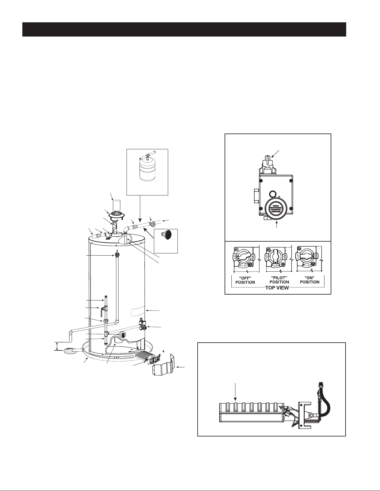
INSTALLATION CONSIDERATIONS
GET TO KNOW YOUR WATER HEATER - GAS MODELS
A Vent Pipe
B Drafthood
C Anode
D Hot Water Outlet
E Outlet
F Insulation
G Gas Supply
H Manual Gas Shut-off Valve
* INSTALL IN ACCORDANCE WITH
LOCAL CODES.
* SEDIMENT TRAP AS REQUIRED
BY LOCAL CODES.
* ALL PIPING MATERIALS TO BE
SUPPLIED BY CUSTOMERS.
S
D
E
C
Q
I Ground Joint Union
J Sediment Trap
K Inner Door
L Outer door
M Union
N Inlet Water Shut-off Valve
O Cold Water Inlet
P Inlet Dip Tube
Q Temperature-Pressure Relief Valve
R Rating Plate
S FlueBafe(s)
T Gas Control Valve/Thermostat
U Drain Valve
V Pilot and Main Burner
W Flue
X Metal Drain Pan
(T)GASCONTROLVALVE/THERMOSTAT
GAS CONTROL KNOB
**INSTALL THERMAL EXPANSION
TANK OR DEVICE IF WATER
A
B
HEATER IS INSTALLED IN A
CLOSED WATER SYSTEM
N
M
O
WATER TEMPERATURE
VACUUM RELIEF
VALVE
*INSTALL PER
LOCAL CODES
P
F
(ADJUSTING DIAL)
G
H
I
U
6” MAXIMUM
AIR GAP
J
WX
**CLOSED WATER SYSTEMS ARE THOSE
WITH BACK FLOW PREVENTION DEVICES
INSTALLED IN THE WATER SERVICE LINE.
R
T
K
FLAME CHARACTERISTICS
V
L
FIGURE 1.
6
CORRECT FLAME
SOFT BLUE
THERMOMETERS(NOTSUPPLIED)
Thermometers should be obtained and eld installed.
Thermometers are installed in the system as a means of detecting
the temperature of the outlet water supply.
This Water Heater has been design certified as complying with
ANSI Z21.10.3-CSA 4.3 current edition for water heaters and is
considered suitable for:
Water (Potable) Heating and Space Heating: All models are
considered suitable for water (potable) heating and space heating.
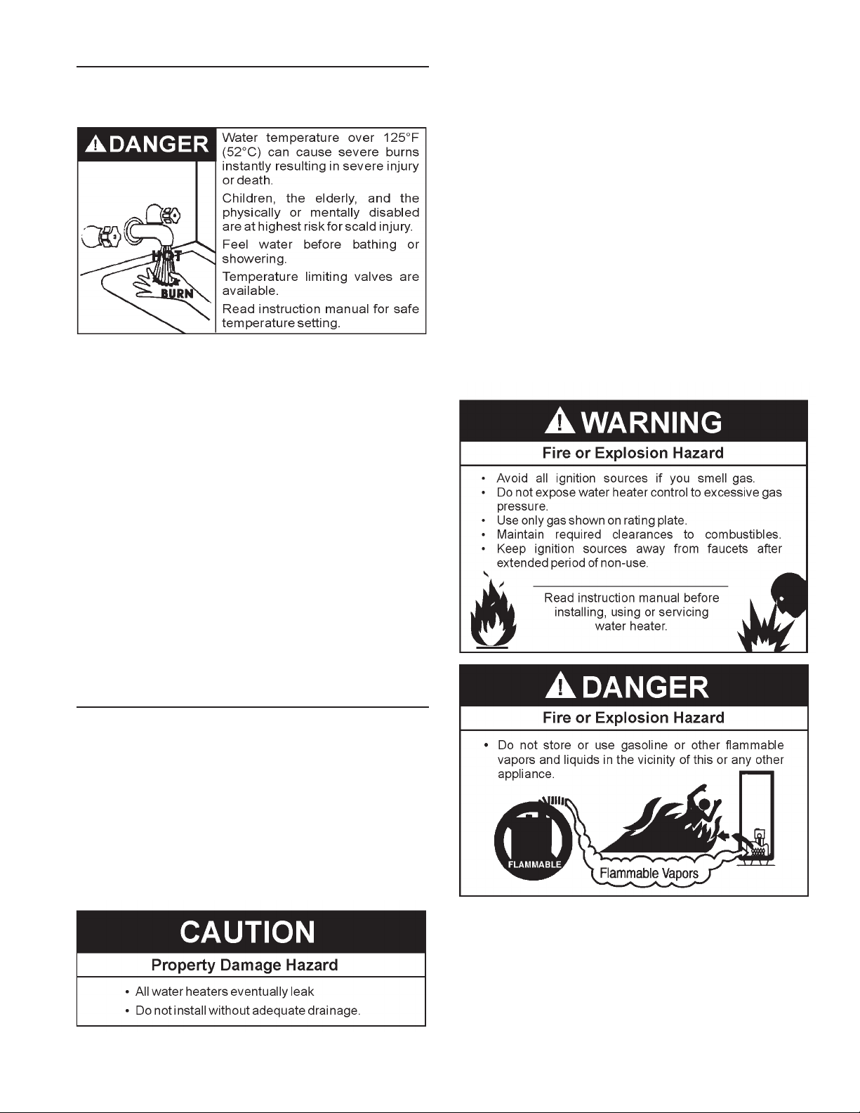
HOTTER WATER CAN SCALD:
Water heaters are intended to produce hot water. Water heated to a
temperature which will satisfy space heating, clothes washing, dish
washing, and other sanitizing needs can scald and permanently injure
you upon contact. Some people are more likely to be permanently
injured by hot water than others. These include the elderly, children,
the inrm, or physically/mentally handicapped. If anyone using hot
water in your home ts into one of these groups or if there is a local
code requiring a certain temperature water at the hot water tap, then
you must take special precautions. In addition to using the lowest
possible temperature setting that satises your hot water needs,
a means such as a *Mixing Valve should be used at the hot water
taps used by these people or at the water heater. Mixing valves are
available at plumbing supply or hardware stores. Consult a qualied
installer or service technician. Follow mixing valve manufacturer’s
instructions for installation of valves. Before changing the factory
setting on the thermostat, read the “Temperature Regulation” section
in this manual, see Figures 17 and 18.
the structure. For this reason, it is not advisable to install water heater
in an attic or upper oor. When such locations cannot be avoided, a
suitable metal drain pan should be installed under the water heater.
Metal Drain pans are available at your local hardware store. Such a
metal drain pan must have a minimum length and width of at least
2” (51 mm) greater than water heater dimensions and must be piped
to an adequate drain. The pan must not restrict combustion air ow.
Water heater life depends upon water quality, water pressure and the
environment in which the water heater is installed. Water heaters are
sometimes installed in locations where leakage may result in property
damage, even with the use of a drain pan piped to a drain. However,
unanticipated damage can be reduced or prevented by a leak detector
or water shut-off device used in conjunction with a piped drain pan.
These devices are available from some plumbing supply wholesalers
and retailers, and detect and react to leakage in various ways:
• Sensors mounted in the drain pan that trigger an alarm or turn off
the incoming water to the water heater when leakage is detected.
• Sensors mounted in the drain pan that turn off the water supply
to the entire home when water is detected in the drain pan.
• Water supply shut-off devices that activate based on the water
pressure differential between the cold water and hot water pipes
connected to the water heater.
• Devices that will turn off the gas supply to a gas water heater
while at the same time shutting off its water supply.
FACTS TO CONSIDER ABOUT THE LOCATION
Carefully choose an indoor location for the new water heater,
because the placement is a very important consideration for
the safety of the occupants in the building and for the most
economical use of the water heater. This water heater is not
for use in manufactured (mobile) homes or outdoor installation.
Whether replacing an old water heater or putting the water heater
in a new location, the following critical points must be observed:
1. Select a location indoors as close as practical to the gas vent or
chimney to which the water heater vent is going to be connected,
and as centralized with the water piping system as possible.
2. Selected location must provide adequate clearances for
servicing and proper operation of the water heater.
Installation of water heater must be accomplished in such a manner that
if the tank or any connections should leak, ow will not cause damage to
INSTALLATIONS IN AREAS WHERE FLAMMABLE LIQUIDS
(VAPORS) ARE LIKELY TO BE PRESENT OR STORED (GARAGES,
STORAGE AND UTILITY AREAS, ETC.): Flammable liquids (such as
gasoline, solvents, propane [LP or butane, etc.] and other substances
such as adhesives, etc.) emit ammable vapors which can be ignited by
a gas water heater’s pilot light or main burner. The resulting ashback
and re can cause death or serious burns to anyone in the area, as well
as property damage. If installation in such areas is your only option, then
installation must be accomplished in a way that the pilot ame and main
burner ame are elevated from oor at least 18 inches. While this may
reduce chances of ammable vapors, from a oor spill being ignited,
gasoline and other ammable substances should never be stored or
7
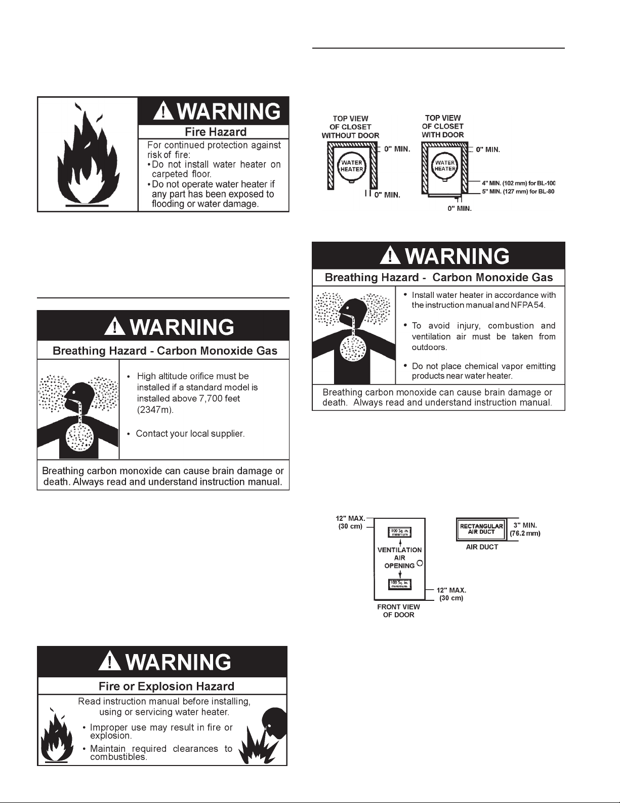
used in the same room or area containing a gas water heater or other
open ame or spark producing appliance. NOTE: Flammable vapors may
be drawn by air currents from other areas of the structure to the appliance.
Also, the water heater must be located and/or protected so it is not
subject to physical damage by a moving vehicle.
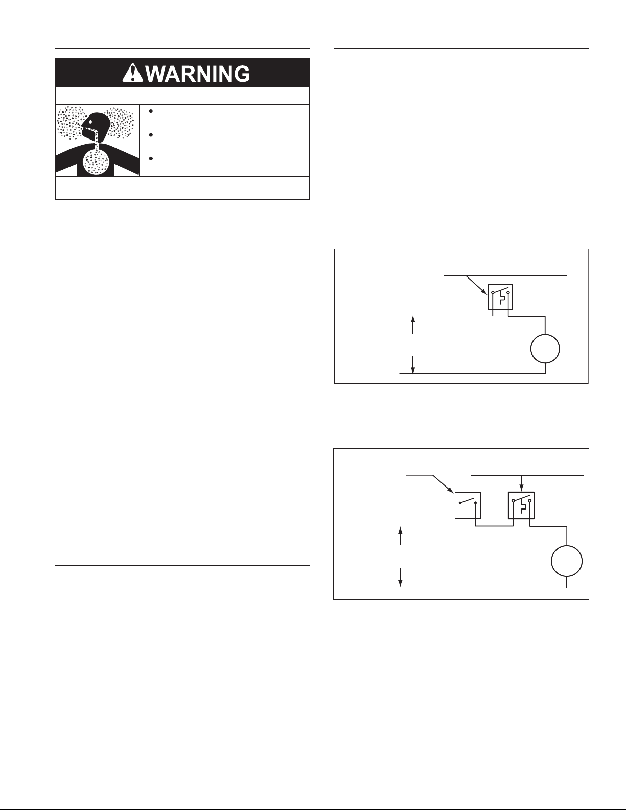
CLEARANCES
Minimum clearances between the water heater and combustible
construction are 0 inch at the sides and rear, 4” (102 mm) for 100
gallon unit and 5” (127 mm) for 75 gallon unit at the front, and 6”
(153 mm) from the vent pipe. Clearance from the top of the jacket
is 12” (305 mm).
This water heater must not be installed directly on carpeting. Carpeting
must be protected by metal or wood panel beneath the water heater
extending beyond the full width and depth of the water heater by at least
3” (76.2 mm) in any direction, or if the water heater is installed in an
alcove or closet, the entire oor must be covered by the panel. Failure
to heed this warning may result in a re hazard.
High Altitude
Water heaters covered in this manual have been tested and approved
for installation at elevations up to 7,700 feet (2,347 m) above sea level.
For installation above 7,700 feet (2,347 m), the water heater’s Btu input
should be reduced at the rate of 4 percent for each 1,000 feet (305
m) above sea level which requires replacement of the burner orice
in accordance with the National Fuel Gas Code ANSI Z223.1/NFPA
54. Contact your local gas supplier for further information.
Failure to replace the standard orice with the proper high altitude
orice when installed at elevations above 7,700 feet (2,347 m)
could result in improper and inefcient operation of the water heater,
producing carbon monoxide gas in excess of the safe limits. This
could result in serious injury or death. Contact your local gas supplier
for any specic changes that may be required in your area.
FIGURE 2.
A gas water heater cannot operate properly without the correct
amount of air for combustion. Do not install in a conned area
such as a closet, unless you provide air as shown in the Facts to
Consider About The Location section. Never obstruct the ow of
ventilation air. If you have any doubts or questions at all, call your
gas supplier. Failure to provide the proper amount of combustion
air can result in a re or explosion and cause death, serious bodily
injury, or property damage.
FIGURE 3.
If this water heater will be used in beauty shops, barber shops,
cleaning establishments, or self-service laundries with dry
cleaning equipment, it is imperative that the water heater or
water heaters be installed so that combustion and ventilation
air be taken from outside these areas.
Propellants of aerosol sprays and volatile compounds, (cleaners,
chlorine based chemicals, refrigerants, etc.) in addition to being
highly ammable in many cases, will also change to corrosive
hydrochloric acid when exposed to the combustion products of
the wa te r heater. The results can be hazardous, and also cause
product failure.
8
INSULATION BLANKETS
CIRCULATING PUMP WIRING DIAGRAM
CIRCULATING PUMP WIRING DIAGRAM
Breathing Hazard - Carbon Monoxide Gas
Do not obstruct water heater air intake
with insulating blanket.
Gas and carbon monoxide detectors
are available.
Install water heater in accordance with
the instruction manual.
Breathing carbon monoxide can cause brain damage or
death. Always read and understand instruction manual.
Insulation blankets are available to the general public for
external use on gas water heaters but are not necessary
with these products. The purpose of an insulation blanket is
to reduce the standby heat loss encountered with storage
tank heaters. The water heaters covered by this manual meet
or exceed the Energy Policy Act standards with respect to
insulation and standby heat loss requirements, making an
insulation blanket unnecessary.
Should you choose to apply an insulation blanket to this heater,
you should follow these instructions. See the Installation
Considerations section of this manual for identification
of components mentioned below. Failure to follow these
instructions can restrict the air flow required for proper
combustion, potentially resulting in fire, asphyxiation, serious
personal injury or death.
• DO NOT apply insulation to the top of the water heater, as
this will interfere with safe operation of the draft hood.
• DO NOT cover the thermostat or the TemperaturePressure Relief Valve.
• DO NOT allow the insulation to come within 2 inches (5
cm) of the floor to prevent blockage of combustion air flow
to the burner.
• DO NOT cover the instruction manual. Keep it on the side
of the water heater or nearby for future reference.
• DO obtain new warning and instruction labels from the
manufacturer for placement on the blanket directly over
the existing labels.
• DO inspect the insulation blanket frequently to make
certain it does not sag, thereby obstructing the
combustion air flow.
HARD WATER
Whe re har d wate r condi tion s exi s t, wa ter so f teni ng or th e thre s hold
type of water treatment is recommended. This will protect the
dishwashers, coffee urns, water heaters, water piping and other
equipment. See the Maintenance Section in this manual for
sediment and lime scale removal procedures.
CIRCULATION PUMPS
A circulating pump is used when a system requires a circulating
loop or there is a storage tank used in conjunction with the
water heater. See Water Piping Diagrams in this manual for
installation location of circulating pumps.
See the Circulation Pump Wir ing Diagrams below for electrical
hookup information. Install in accordance with the current
edition of the National Electrical Code, NFPA 70.
All bronze or stainless steel circulating pumps are recommended
for used with commercial water heaters.
Some circulating pumps are manufactured with sealed bearings
and do not require further lubrication. Some circulating pumps
must be periodically oiled. Refer to the pump manufacturer’s
instructions for lubrication requirements.
STORAGE TANK OR BUILDING RECIRCULATION
FIELD SUPPLIED TEMPERATURE CONTROL
INSTALLED IN THE STORAGE TANK
NOTE: USE SEPARATE 120 VAC POWER
SUPPLY FOR PUMP CIRCUIT. DO NOT
SHARE POWER WITH WATER HEATER AS THIS
MAY CAUSE ELECTRICAL LINE NOISE AND
LEAD TO ERRATIC CONTROL SYSTEM
OPERATION.
L1 HOT
L2 NEUTRAL
120 VAC
POWER
DISHWASHER LOOP WITH TOGGLE SWITCH
DISHWASHER
TOGGLE
SWITCH
NOTE: USE SEPARATE 120 VAC POWER
SUPPLY FOR PUMP CIRCUIT. DO NOT
SHARE POWER WITH WATER HEATER AS
THIS MAY CAUSE ELECTRICAL LINE NOISE
AND LEAD TO ERRATIC CONTROL SYSTEM
OPERATION.
L1 HOT
120 VAC
POWER
L2 NEUTRAL
OR CIRCULATING LOOP RETURN LINE
CIRC
PUMP
MOTOR
FIGURE 4.
FIELD SUPPLIED TEMPERATURE
CONTROL INSTALLED IN THE
CIRCULATING LOOP RETURN LINE
CIRC
PUMP
MOTOR
FIGURE 5.
9
HOT WATER
INLET
INSTALLATION REQUIREMENTS
GAS SUPPLY SYSTEMS
Low pressure building gas supply systems are dened as those
systems that cannot under any circumstances exceed 14” W.C.
(1/2 PSI Gauge). These systems do not require pressure regulation.
Measurements should be taken to insure that gas pressures are stable
and fall within the requirements stated on the water heater rating plate.
readings should be taken with all gas burning equipment off (static
pressure) and with all gas burning equipment running at maximum rate
(dynamic pressure). The gas supply pressure must be stable within 1.5”
W.C. from static to dynamic pressure to provide good performance.
Pressure drops that exceed 1.5” W.C. may cause rough starting, noisy
combustion or nuisance outages. Increases or spikes in static pressure
during off cycles may cause failure to ignite or in severe cases damage
to appliance gas valves. If your low pressure system does not meet
these requirements, the installer is responsible for the corrections.
High Pressure building supply systems use pressures that exceed
14” W.C. (1/2 PSI Gauge). These systems must use eld supplied
regulators to lower the gas pressure to less than 14” W.C. (1/2 PSI
Gauge). Appliances require gas regulators that are properly sized for the
water heater input and deliver the rating plate specied pressures. Gas
supply systems where pressure exceeds 5 PSI often require multiple
regulators to achieve desired pressures. Systems in excess of 5 PSI
building pressure should be designed by gas delivery professionals
for best performance. Water heaters connected to gas supply systems
that exceed 14” W.C. (1/2 PSI Gauge) at any time must be equipped
with a gas supply regulator.
GAS PRESSURE REQUIREMENTS
100 gallon natural gas model requires a minimum gas supply pressure
of 5” w.c. (1.25 kPa); 75 gallon natural gas model requires a minimum
gas supply pressure of 6” w.c. (1.49 kPa). The minimum supply
pressure is measured while gas is owing (dynamic pressure). The
supply pressure (dynamic) should never fall below the specied
minimum supply pressure. The supply pressure should be measured
with all gas red appliances connected to the common main ring at full
capacity. If the supply pressure drops more than 1.5” W.C. (0.37 kPa)
as gas begins to ow to the water heater then the supply gas system
including the gas line and/or the gas regulator may be restricted or
undersized. See Supply Gas regulator section and Gas Piping section
of this manual. The gas valve on all models has a maximum gas supply
pressure limit of 14” W.C. (3.48 kPa) The maximum supply pressure
is measured while gas is not owing (static pressure).
SUPPLY GAS REGULATOR
The maximum allowable gas supply pressure for this water heater
is 14.0 inches W.C. (3.48 kPa). Install a positive lock-up gas pressure
regulator in the gas supply line if inlet gas pressure can exceed 14.0
inches W.C. (3.48 kPa) at any time. regulators must be sized/used
according to manufacturer’s specications.
If a positive lock-up regulator is required follow these instructions:
1. Positive lock-up gas pressure regulators must be rated at or above
the input Btu/hr rating of the water heater they supply.
2. Positive lock-up gas pressure regulator(s) should be installed no
closer than 3 feet (1 meter) and no farther than 8 feet (2.4 meters)
of equivalent length from the water heater’s inlet gas connection.
3. After installing the positive lock-up gas pressure regulator(s) an initial
nominal supply pressure setting of 7.0” W.C. while the water heater
is operating is recommended and will generally provide good
water heater operation. Some additional adjustment maybe required
later to maintain a steady gas supply pressure.
4. When installing multiple water heaters in the same gas supply
system it is recommended that individual positive lock-up gas
pressure regulators be installed at each unit.
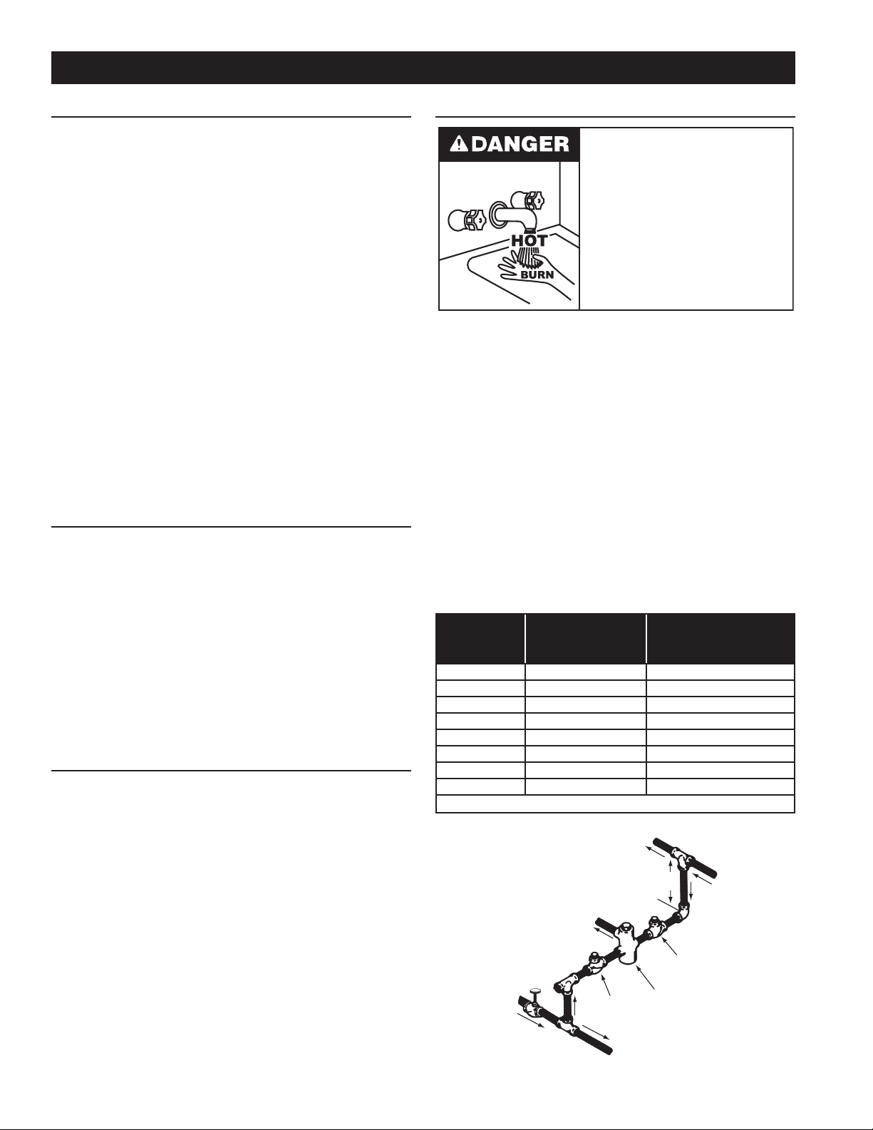
MIXING VALVES
Water temperature over 125°F (52°C)
can cause severe burns instantly
resulting in severe injury or death.
Children, the elderly and the physically
or mentally disabled are at highest risk
for scald injury.
Feel water before bathing or showering.
Temperature limiting devices such as
mixing valves must be installed when
required by codes and to ensure safe
temperatures at fixtures.
Water heated to a temperature which will satisfy clothes washing, dish
washing, and other sanitizing needs can scald and cause permanent
injury upon contact. Short repeated heating cycles caused by small
hot water uses can cause temperatures at the point of use to exceed
the water heater’s temperature setting by up to 20°F (11°C).
Some people are more likely to be permanently injured by hot water
than others. These include the elderly, children, the inrm and the
physically/mentally disabled. Table 2 shows the approximate timeto-burn relationship for normal adult skin. If anyone using hot water
provided by the water heater being installed ts into one of these
groups or if there is a local code or state law requiring a certain water
temperature at the point of use, then special precautions must be taken.
In addition to using the lowest possible temperature setting that
satises demand of the application a Mixing Valve should be installed
at the water heater or at hot water taps to further reduce system water
temperature. See Figure 6.
Mixing valves are available at plumbing supply stores. Consult
a Qualied Installer or Service Technician. Follow mixing valve
manufacturer’s instructions for installation of the valves.
TABLE 2.
Water
Temperature °F
110
116 (pain threshold)
116 35 minutes 45 minutes
122 1 minute 5 minutes
131 5 seconds 25 seconds
140 2 seconds 5 seconds
149 1 second 2 seconds
154 instantaneous 1 second
(U.S. Government Memorandum, C.P.S.C., Peter L. Armstrong, Sept. 15,1978)
COLD
WATER
INLET
Time for
1st Degree Burn
(Less Severe Burns)
(normal shower temp.)
OUTLET
TEMPERED WATER
OUTLET
CHECK
VALV E
FIGURE 6.
10
Time for Permanent Burns
2nd & 3rd Degree
(Most Severe Burns)
12” TO 15”
(30-38 cm)
CHECK
VALV E
MIXING
VALV E
TO TANK
 Loading...