

Page 1

WARNING: If the information in these
instructions is not followed exactly, a fire
or explosion may result causing property
damage, personal injury or death.
Do not store or use gasoline or other
flammable vapors and liquids in the
vicinity of this or any other appliance.
WHAT TO DO IF YOU SMELL GAS:
Do not try to light any appliance.
Do not touch any electrical switch; do
not use any phone in your building.
Immediately call your gas supplier
from a neighbor’s phone. Follow the
gas supplier’s instructions.
If you cannot reach your gas supplier,
call the fire department.
Installation and service must be
performed by a qualified installer,
service agency or the gas supplier.
•
•
•
•
Instruction Manual
COMMERCIAL GAS WATER HEATERS
MODEL 154
SERIES 120/121
INSTALLATION - OPERATION
- SERVICE - MAINTENANCE
We appreciate your condence in our products.
Thank you for buying this energy efcient water heater.
PRINTED 0819
KEEP THIS MANUAL IN THE POCKET ON HEATER FOR FUTURE REFERENCE
WHENEVER MAINTENANCE ADJUSTMENT OR SERVICE IS REQUIRED.
Read and understand this instruction
manual and the safety messages
herein before installing, operating or
servicing this water heater.
Failure to follow these instructions and
safety messages could result in death
or serious injury.
This manual must remain with the
water heater.
• For Your Safety •
AN ODORANT IS ADDED TO THE GAS USED
1
BY THIS WATER HEATER.
100322746 2000573801 (Rev B)
Page 2

CONTENTS
SAFE INSTALLATION, USE, AND SERVICE..................... 3
APPROVALS ...................................................................... 3
GENERAL SAFETY INFORMATION .................................. 4
Precautions ....................................................................4
Grounding Instructions ...................................................4
Hydrogen Gas Flammable .............................................4
INTRODUCTION ................................................................ 6
Abbreviations Used ........................................................6
Qualications ..................................................................6
Preparing for the Installation ..........................................6
FEATURES AND COMPONENTS ..................................... 7
The Eliminator (self-cleaning system) ............................7
INSTALLATION CONSIDERATIONS ................................. 9
Rough-In Dimensions .....................................................9
Locating the Water Heater .............................................10
NSF Leg Kit ................................................................... 11
Insulation Blanket .......................................................... 11
High Altitude Installations ..............................................12
INSTALLATION REQUIREMENTS .................................. 13
Gas Supply Systems .....................................................13
Supply Gas Regulator ...................................................13
Power Supply ................................................................13
Water Temperature Control and Mixing Valves .............14
Dish-washing Machines ................................................14
Closed Water Systems ..................................................14
Thermal Expansion .......................................................14
Temperature-Pressure Relief Valve ............................... 15
Contaminated Air ...........................................................16
Air Requirements ...........................................................16
VENTING INSTALLATION ............................................... 18
Fresh Air Openings For Conned Spaces .....................19
Outdoor Air Through One Opening ...............................19
Mechanical venting ........................................................22
WATER HEATER INSTALLATION .................................... 23
Water Line Connections ................................................23
T&P Valve Discharge Pipe ............................................23
Installation Diagrams - Top Inlet/Outlet Usage ..............24
Water Heater Wiring ......................................................24
Supply Gas Line Installation ..........................................25
OPERATION ..................................................................... 27
Prior to Start Up .............................................................27
SEQUENCE OF OPERATION ......................................... 27
Lighting & Operation Label ............................................29
Adjustments ...................................................................31
Checking the Venting ....................................................31
Checking the Input ........................................................32
MAINTENANCE ............................................................... 33
Venting System .............................................................33
Remote Storage Tank Temperature Control ..................33
Temperature-Pressure Relief Valve Test .......................33
Anode Rod Inspection ...................................................33
Draining and ushing .....................................................34
Removing Lime Deposits from Tank Type
Commercial Water Heaters ...........................................34
Deliming Solvents ..........................................................35
Tank Cleanout Procedure ..............................................35
Deliming Using Flo-Jug Method ....................................35
Pilot Burner ....................................................................36
Main Burner ...................................................................37
Gas Control Valve..........................................................37
SERVICE .......................................................................... 38
Electrical Servicing ........................................................38
TROUBLESHOOTING ..................................................... 39
Ignition Module ..............................................................39
Flue Damper ..................................................................39
Efkal RVGP-KSF-Series Flue Damper Trouble Shooting
Guide .............................................................................40
FOR YOUR INFORMATION ............................................. 42
Start Up Conditions .......................................................42
Operational Conditions ..................................................42
WATER PIPING DIAGRAMS ............................................ 43
MANIFOLD KITS .............................................................. 58
2
Page 3

SAFE INSTALLATION, USE, AND SERVICE
The proper installation, use, and servicing of this water heater
is extremely important to your safety and the safety of others.
Many safety-related messages and instructions have been
provided in this manual and on your own water heater to warn
This is the safety alert symbol. It is used to alert you to
potential personal injury hazards. Obey all safety
messages that follow this symbol to avoid possible
injury or death.
DANGER indicates an imminently
DANGER
WARNING
CAUTION
CAUTION
hazardous situation which, if not avoided,
will result in injury or death.
WARNING indicates a potentially hazardous
situation which, if not avoided, could result
in injury or death.
CAUTION indicates a potentially hazardous
situation which, if not avoided, could result in
minor or moderate injury.
CAUTION used without the safety alert
symbol indicates a potentially hazardous
situation which, if not avoided, could result in
property damage.
you and others of a potential injury hazard. Read and obey all
safety messages and instructions throughout this manual. It
is very important that the meaning of each safety message is
understood by you and others who install, use, or service this
water heater.
All safety messages will generally tell you about the type of
hazard, what can happen if you do not follow the safety message,
and how to avoid the risk of injury.
The California Safe Drinking Water and Toxic Enforcement Act
requires the Governor of California to publish a list of substances
known to the State of California to cause cancer, birth defects,
or other reproductive harm, and requires businesses to warn of
potential exposure to such substances.
APPROVALS
Warning: This product contains a chemical known to the
State of California to cause cancer, birth defects,
or other reproductive harm. This appliance
can cause low level exposure to some of the
substances listed in the Act.
Note: ASME construction is optional on the water heaters
covered in this manual.
3
Page 4

GENERAL SAFETY INFORMATION
PRECAUTIONS
DO NOT USE THIS WATER HEATER IF ANY PART HAS BEEN
EXPOSED TO FLOODING OR WATER DAMAGE. Immediately
call a qualied service agency to inspect the water heater and
to make a determination on what steps should be taken next.
If the unit is exposed to the following, do not operate heater until
all corrective steps have been made by a qualied service agency.
1. External re.
2. Damage.
3. Firing without water.
GROUNDING INSTRUCTIONS
This water heater must be grounded in accordance with the
National Electrical Code
and/or local codes. These codes must be
followed in all cases. Failure to ground this water heater properly
may also cause erratic control system operation.
This water heater must be connected to a grounded metal,
permanent wiring system; or an equipment grounding conductor
must be run with the circuit conductors and connected to the
equipment grounding terminal or lead on the water heater.
HYDROGEN GAS FLAMMABLE
Hydrogen gas can be produced in a hot water system served
by this water heater that has not been used for a long period of
time (generally two weeks or more). Hydrogen gas is extremely
ammable. To reduce the risk of injury under these conditions,
it is recommended that a hot water faucet served by this water
heater be opened for several minutes before using any electrical
appliance connected to the hot water system. If hydrogen is
present there will probably be an unusual sound such as air
escaping through the pipe as the water begins to ow. THERE
SHOULD BE NO SMOKING OR OPEN FLAME NEAR THE
FAUCET AT THE TIME IT IS OPEN.
Explosion Hazard
Flammable hydrogen gases
may be present.
Keep all ignition sources away
from faucet when turning on
hot water.
Read and understand this instruction
manual and the safety messages
herein before installing, operating or
servicing this water heater.
Failure to follow these instructions and
safety messages could result in death
or serious injury.
This manual must remain with the
water heater.
Water temperature over 125°F (52°C)
can cause severe burns instantly
resulting in severe injury or death.
Children, the elderly and the
physically or mentally disabled are at
highest risk for scald injury.
Feel water before bathing or
showering.
Temperature limiting devices such as
mixing valves must be installed
when required by codes and to
ensure safe temperatures at fixtures.
Explosion Hazard
Overheated water can cause
water tank explosion.
Properly sized temperature and
pressure relief valve must be
installed in the opening provided.
CAUTION
Improper installation, use and service may result
in property damage.
Do not operate water heater if exposed to flooding or
•
water damage.
Inspect anode rods regularly, replace if damaged.
•
Install in location with drainage.
•
Fill tank with water before operation.
•
Properly sized thermal expansion tanks are required on all
•
closed water systems.
Refer to this manual for installation and service.
4
Page 5

Fire or Explosion Hazard
Do not store or use gasoline or other flammable vapors and
liquids in the vicinity of this or any other appliance.
Avoid all ignition sources if you smell gas.
Do not expose water heater controls to excessive gas
pressure.
Use only the gas shown on the water heater rating label.
Maintain required clearances to combustibles.
Keep ignition sources away from faucets after extended
periods of non-use.
Read instruction manual before
installing, using or servicing
water heater.
Breathing Hazard - Carbon Monoxide Gas
Do not obstruct water heater air intake
with insulating blanket.
Gas and carbon monoxide detectors
are available.
Install water heater in accordance with
the instruction manual.
Breathing carbon monoxide can cause brain damage or
death. Always read and understand instruction manual.
CAUTION
Property Damage Hazard
All water heaters eventually leak.
•
Fire Hazard
For continued protection against
risk of fire:
Do not install water heater on
carpeted floor.
Do not operate water heater if
exposed to flooding or water
damage.
Fire and Explosion Hazard
Use joint compound or Teflon tape
compatible with propane gas.
Leak test gas connections before
placing water heater in operation.
Disconnect gas piping at main
gas shutoff valve before leak
testing heater.
Install sediment trap in
accordance with NFPA 54.
Fire and Explosion Hazard
Do not use water heater with any gas
other than the gas shown on the rating
label.
Excessive gas pressure to gas valve can
cause serious injury or death.
Turn off gas lines during installation.
Contact a qualified installer or service
agency for installation and service.
Do not install without adequate drainage.
•
Electrical Shock Hazard
Turn off power at the branch circuit
•
breaker serving the water heater
before performing any service.
Label all wires prior to disconnecting
•
when performing service. Wiring errors
can cause improper and dangerous
operation.
Verify proper operation after servicing.
•
Failure to follow these instructions can
•
result in personal injury or death.
Jumping out control circuits or components can
result in property damage, personal injury or death.
Service should only be performed by a qualified service
•
technician using proper test equipment.
Altering the water heater controls and/or wiring in any way
•
could result in permanent damage to the controls or water
heater and is not covered under the limited warranty.
Any bypass or alteration of the water
heater controls and/or wiring will result
in voiding the appliance warranty.
5
Page 6

INTRODUCTION
Thank You for purchasing this water heater. Properly installed
and maintained, it should give you years of trouble free service.
ABBREVIATIONS USED
Abbreviations found in this Instruction Manual include :
• ANSI - American National Standards Institute
• ASME - American Society of Mechanical Engineers
• AHRI - Air Conditioning, Heating and Refrigeration Institute
• NEC - National Electrical Code
• NFPA - National Fire Protection Association
• UL - Underwriters Laboratory
• CSA - Canadian Standards Association
QUALIFICATIONS
QUALIFIED INSTALLER OR SERVICE AGENCY
Installation and service of this water heater requires ability
equivalent to that of a Qualied Agency (as dened by ANSI
below) in the eld involved. Installation skills such as plumbing,
air supply, venting, gas supply, and electrical supply, are required
in addition to electrical testing skills when performing service.
ANSI Z223.1:
or company that either in person or through a representative is
engaged in and is responsible for (a) the installation, testing or
replacement of gas piping or (b) the connection, installation,
testing, repair, or servicing of appliances and equipment; that
is experienced in such work; that is familiar with all precautions
required; and that has complied with all the requirements of the
authority having jurisdiction.”
If you are not qualied (as dened by ANSI above) and licensed or
certied as required by the authority having jurisdiction to perform
a given task do not attempt to perform any of the procedures
described in this manual. If you do not understand the instructions
given in this manual do not attempt to perform any procedures
outlined in this manual.
“Qualied Agency” - “Any individual, rm, corporation
PREPARING FOR THE INSTALLATION
1. Read the entire manual before attempting to install or operate
the water heater. Pay close attention to the
Information
water heater may not operate safely. It could cause property
damage, injury and/or death.
This manual contains instructions for the installation,
operation, and maintenance of the water heater. It also
contains warnings throughout the manual that you must
read and be aware of. All warnings and all instructions are
essential to the proper operation of the water heater and
your safety.
2. Be sure to turn off power when working on or near the electrical
system of the water heater. Never touch electrical components
with wet hands or when standing in water.
3. The installation must conform to all instructions contained in
this manual and the local code authority having jurisdiction.
These shall be carefully followed in all cases. Authorities
having jurisdiction should be consulted before installation
begins if there are any questions regarding compliance with
local, state or national codes.
4. After reading this manual, if you have any questions or do
not understand any portion of the instructions, call the toll
free number on the back cover of this manual for technical
assistance. In order to expedite your request, please have the
full Model, Serial and Series numbers of the water heater you
are working with available for the technician. This information
is located on the water heater’s rating label.
5. Carefully plan the placement of the water heater. Correct
combustion, vent action, and vent pipe installation are very
important in preventing death from possible carbon monoxide
poisoning and res.
Examine the location to ensure that it complies with the
requirements in
the Water Heater
(page 4). If you don’t follow the safety rules, the
Rough-In Dimensions
(page 10).
(page 9) and
General Safety
Locating
6. For installation in California this water heater must be braced or
anchored to avoid falling or moving during an earthquake. See
instructions for correct installation procedures. Instructions
may be obtained from California Ofce of the State Architect,
1102 Q Street, Suite 5100, Sacramento, CA 95811.
7. Massachusetts Code requires this water heater to be installed
in accordance with Massachusetts 248-CMR 2.00: State
Plumbing Code and 248-CMR 5.00.
6
Page 7

FEATURES AND COMPONENTS
THE ELIMINATOR (SELF-CLEANING SYSTEM)
These units include The Eliminator (Self-Cleaning System)
installed in the front water inlet. See
Figure 1
. The Eliminator
inlet tube can only be used in the front water inlet connection.
Do not install the Eliminator inlet tube in either the top or back
inlet water connection.
The Eliminator must be oriented correctly for proper function.
There is a marked range on pipe nipple portion of the Eliminator,
that must be aligned with top of inlet spud. A label above the
jacket hole has an arrow that will point to marked portion of
pipe nipple if the orientation is correct. If the arrow does not
point within the marked range on pipe nipple, adjust the pipe
nipple to correct. A pipe union is supplied with the Eliminator to
reduce probability of misaligning the Eliminator accidentally while
tightening the connection to inlet water supply line. Improper
orientation of the Eliminator can cause poor performance of
heater and can signicantly reduce outlet water temperatures
during heavy draws.
Figure 1. Eliminator Self Cleaning System
Contact your dealer or service agent if continued high limit switch
operation occurs.
Figure 2. Digital Thermostat
ELECTRONIC IGNITION CONTROL
Each heater is equipped with a Honeywell ignition module. The
solid state ignition control ignites the pilot burner gas by creating
a spark at the pilot assembly. See
Figure 3
. Pilot gas is ignited
and burns during each running cycle. The main burner and pilot
gases are cut off during the OFF cycle. Pilot gas ignition is proven
by the pilot sensor. Main burner ignition will not occur if the pilot
sensor does not rst sense pilot ignition.
Note: The Eliminator may have 1, 3 or 7 cross tubes.
HIGH LIMIT SWITCH
The digital thermostat (
Figure 2)
contains the high limit (energy
cutout) switch. The high limit switch interrupts main burner gas
ow should the water temperature reach 203°F (95°C).
In the event of high limit switch operation, the water heater
cannot be restarted unless the water temperature is reduced to
approximately 120°F (49°C). The high limit reset button on the
front of the control then needs to be depressed.
Continued manual resetting of high limit control, preceded by
higher than usual water temperature is evidence of high limit
switch operation. The following is a possible reason for high limit
switch operation:
• A malfunction in the thermostatic controls would allow the gas
control valve to remain open causing water temperature to
exceed the thermostat setting. The water temperature would
continue to rise until high limit switch operation.
Figure 3. Honeywell Ignition Module
7
Page 8

AUTOMATIC FLUE DAMPER
This unit is equipped with an automatic ue damper that reduces
heat loss during the OFF cycles. The automatic ue damper
drive assembly is a eld replaceable part and may be obtained
by contacting A. O. Smith Corporation at 500 Tennessee Waltz
Parkway, Ashland City, TN 37015, 1-800-433-2545.
Each automatic ue damper drive assembly is equipped with a
“Service Switch”, as shown in
Figure 4
The “Service Switch” has 2 positions: AUTOMATIC OPERATION
and HOLD OPEN DAMPER. For normal operation the switch
should be in the AUTOMATIC OPERATION position.
If there is a problem with the damper the “Service Switch” can be
placed in the HOLD OPEN DAMPER position. When the switch
is placed in the HOLD OPEN DAMPER position the damper
disc will rotate to the open position and the heater may be used
until vent assembly is repaired or replaced. DO NOT turn the
damper disc manually; damage will occur to the drive assembly
if operated manually. Refer to TESTING DAMPER OPERATION
section of this manual for additional information.
Figure 4. Flue Damper
UNCRATING
The heater is shipped with the ue damper already installed. The
wiring conduit runs from the thermostat to the damper drive cover.
Before turning unit on, check to make sure the wiring conduit is
securely plugged into damper drive.
8
Page 9

ROUGH-IN DIMENSIONS
INSTALLATION CONSIDERATIONS
Figure 5. Rough-In Dimensions
Table 1. Rough-In Dimensions
Connections
Model
154
Input Rate
BTU/Hr.
154,000 BTU/Hr
45 Kw/Hr
Approx
Tank
Cap. A B C D E F
81 Gal
67-1/2”
4-1/2”
62”
53-5/8”
307 L
171 cm
12 cm
157 cm
136 cm
20-1/2”
52 cm
21”
53 cm
Gas
Inlet
G H
1/2”
1/2”
Vent
Dia
I J
54-5/8”
139 cm6”15 cm
Top Front Back Top Front Back Std. Asme
27-3/4”
1-1/2" NPT
1-1/2" NPT
71 cm
1-1/2" NPT
1-1/2" NPT
1-1/2" NPT
1-1/2" NPT
1-1/2" NPT
1-1/2" NPT
1-1/2" NPT
1-1/2" NPT
1-1/2" NPT
1-1/2" NPT
Table 2. Gas Pressure Requirements
Model
All 3.5" W.C. (0.87 kPa) 10.0" WC (2.49 kPa) 4.5" W.C. (1.12 kPa) 11.0" W.C. 2.74 kPa) 14” W. C. (3.48 kPa) 14” W. C. (3.48 kPa) 120/60 120/60 <5 <5
*Manifold Pressure Minimum Supply Pressure Maximum Supply Pressure Volts/ Hz Amperes
Natural
Natural Gas Propane Gas Natural Gas Propane Gas Natural Gas Propane Gas
Gas
Propane
Gas
Natural
Table 3. Recovery Capacities 120-400/A Models
Input
Model
Btu/hr kW
154 154,000 45
APPROX.
GAL.
CAP.
81 Gal
306 L
Thermal
Efciency%
80
°F 30°F 40°F 50°F 60°F 70°F 80°F 90°F 100°F 110°F 120°F 130°F 140°F
°C 17°C 22°C 28°C 33°C 39°C 44°C 50°C 56°C 61°C 67°C 72°C 78°C
GPH 498 373 299 249 213 187 166 149 136 124 115 107
LPH 1885 1412 1132 943 806 708 628 564 515 469 435 405
U. S. Gallons/hr & liters/hr at temperature rise indicated
Gas
Approximate
Ship. WeightInlet Outlet
470 Lbs
NA
21 3 Kg
Propane
Gas
9
Page 10

LOCATING THE WATER HEATER
When installing the heater, consideration must be given to
proper location. Location selected should be as close to the
stack or chimney as practicable, with adequate air supply and
as centralized with the piping system as possible.
The heater must not be located in an area where it will be subject
to freezing.
Locate it near a oor drain. The heater should be located in an
area where leakage from heater or connections will not result
in damage to adjacent area or to lower oors of the structure.
CAUTION
Property Damage Hazard
All water heaters eventually leak.
•
Do not install without adequate drainage.
•
Fire or Explosion Hazard
Do not store or use gasoline or other flammable vapors and
liquids in the vicinity of this or any other appliance.
Avoid all ignition sources if you smell gas.
Do not expose water heater controls to excessive gas
pressure.
Use only the gas shown on the water heater rating label.
Maintain required clearances to combustibles.
Keep ignition sources away from faucets after extended
periods of non-use.
Read instruction manual before
installing, using or servicing
water heater.
When such locations cannot be avoided, a suitable metal drain
pan should be installed under heater. Such pans should be
fabricated with sides at least 2” deep, with length and width at
least 2” greater than diameter of heater and must be piped to
an adequate drain. Pan must not restrict combustion air ow.
CLEARANCES
This heater is approved for installation on combustible ooring
in an alcove when the minimum clearance from combustion or
non-combustible construction is followed as indicated in
(page 10) and
Table 4
.
Figure 6
In all installations the minimum combustible clearances from
draft hood surface or vent piping shall be 6” (152mm). Vent
piping passing through a combustible wall or ceiling must be
a continuous run (no joints) and retain 6” (152mm) clearance
unless an approved reducing thimble is used.
A service clearance of 24” (610mm) should be maintained from
serviceable parts, such as relief valves, bafes, thermostats,
cleanout openings or drain valves.
Table 4. Installation Clearances
Model
154 1” (2.54 cm) 1” (2.54 cm) 1” (2.54 cm) 12” (30.48 cm)
A
(RIGHT SIDE)B(LEFT SIDE)C(BACK)
D
(CEILING)
There is a risk in using fuel burning appliances such as gas water
heaters in rooms, garages or other areas where gasoline, other
ammable liquids or engine driven equipment or vehicles are
stored, operated or repaired. Flammable vapors are heavy and
travel along the oor and may be ignited by the heater’s igniter
or main burner ames causing re or explosion. Some local
codes permit operation of gas appliances in such areas if they
are installed 18” or more above the oor. This may reduce the
risk if location in such an area cannot be avoided.
Do not install this water heater directly on a carpeted oor. A re
hazard may result. Instead the water heater must be placed on a
metal or wood panel extending beyond the full width and depth
by at least 3 inches in any direction. If the heater is installed in a
carpeted alcove, the entire oor shall be covered by the panel.
Also, see the DRAINING requirements in
Maintenance
(page 33).
The heater shall be located or protected so it is not subject to
physical damage by a moving vehicle.
Flammable items, pressurized containers or any other potential
re hazardous articles must never be placed on or adjacent to
the heater. Open containers or ammable material should not
be stored or used in the same room with the heater.
Figure 6. Minimum Clearances to Combustible Materials
10
Page 11
NSF LEG KIT
CIRCULATING PUMP WIRING DIAGRAM
STORAGE TANK OR BUILDING RECIRCULATION
CIRCULATING PUMP WIRING DIAGRAM
DISHWASHER LOOP WITH TOGGLE SWITCH
FIELD SUPPLIED TEMPERATURE
CONTROL INSTALLED IN THE
CIRCULATING LOOP RETURN LINE
DISHWASHER
TOGGLE
SWITCH
CIRC
PUMP
MOTOR
L1 HOT
L2 NEUTRAL
120 VAC
POWER
NOTE: USE SEPARATE 120 VAC POWER
SUPPLY FOR PUMP CIRCUIT. DO NOT SHARE
POWER WITH WATER HEATER AS THIS MAY
CAUSE ELECTRICAL LINE NOISE AND LEAD
TO ERRATIC CONTROL SYSTEM OPERATION.
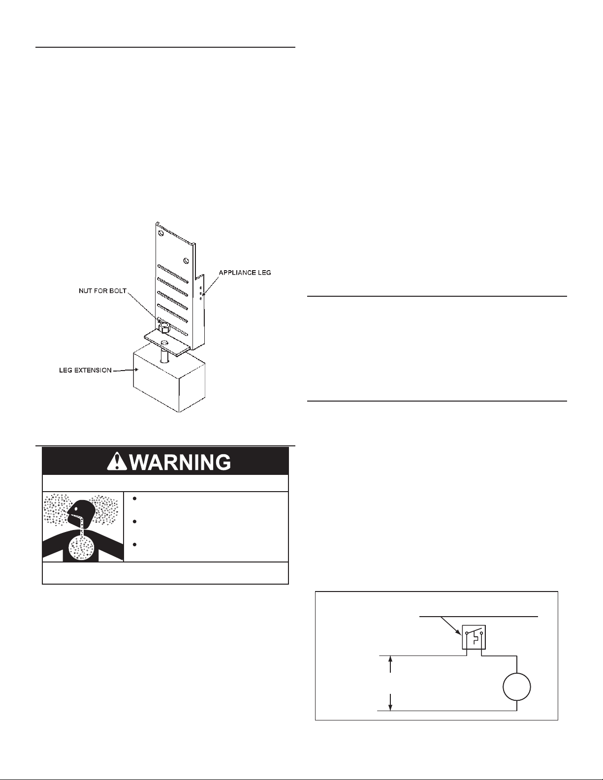
The NSF Leg Kit (part number 100109227) is needed only
for applications that must conform to NSF/ANSI Standard 5.
Installation of the NSF leg kit will increase the height of the unit
and all connection points by 3 inches. See
Figure 7
.
Follow these steps to install the Leg Kit:
1. Unit needs to be lifted in a way not to damage unit or laid on it’s
side to access the bottom of the legs.
2. Slide leg extension under leg and the bolt up through the bottom
hole located in the bottom of the leg.
3. Once in place, screw nut down and secure.
4. Front of leg should line up with front of leg extension as shown
to make sure weight of unit is distributed through the leg
extension.
• DO NOT apply insulation to the top of the water heater, as this
will interfere with safe operation of the draft hood.
• DO NOT cover the gas control valve, thermostat or the
Temperature-Pressure Relief Valve.
• DO NOT allow insulation to come within 2” (5 cm) of the
burners, to prevent blockage of combustion air ow to the
burners.
• DO NOT allow insulation to come within 9 inches (23 cm)
of oor, (within 2 inches (5 cm) of bottom cover) to prevent
blockage of combustion air ow to the burners..
• DO NOT cover the instruction manual. Keep it on the side of
the water heater or nearby for future reference.
• DO obtain new warning and instruction labels from the
manufacturer for placement on the blanket directly over the
existing labels.
• DO inspect the insulation blanket frequently to make certain
it does not sag, thereby obstructing combustion air ow.
HARD WATER
Where hard water conditions exist, water softening or the
threshold type of water treatment is recommended. This will
protect the dishwashers, coffee urns, water heaters, water piping
and other equipment.
Figure 7. NSF Leg Kit
INSULATION BLANKET
Breathing Hazard - Carbon Monoxide Gas
Do not obstruct water heater air intake
with insulating blanket.
Gas and carbon monoxide detectors
are available.
Install water heater in accordance with
the instruction manual.
Breathing carbon monoxide can cause brain damage or
death. Always read and understand instruction manual.
Insulation blankets are available to the general public for external
use on gas water heaters but are not necessary with these
products. The purpose of an insulation blanket is to reduce the
standby heat loss encountered with storage tank heaters. The
water heaters covered by this manual meet or exceed the Energy
Policy Act standards with respect to insulation and standby heat
loss requirements, making an insulation blanket unnecessary.
Should you choose to apply an insulation blanket to this heater,
you should follow these instructions. See the
Components
section of this manual for identication of components
mentioned below. Failure to follow these instructions can restrict
the air ow required for proper combustion, potentially resulting
in re, asphyxiation, serious personal injury or death.
Features and
See the Maintenance Section in this manual for sediment and
lime scale removal procedures.
CIRCULATION PUMPS
A circulating pump is used when a system requires a circulating
loop or there is a storage tank used in conjunction with the water
heater. See
Water Piping Diagrams
(page 43) in this manual for
installation location of circulating pumps.
See the circulation pump wiring diagrams,
Figure 8
and
for electrical hookup information. Install in accordance with the
current edition of the
National Electrical Code, NFPA 70
.
All-bronze circulating pumps are recommended for used with
commercial water heaters.
Some circulating pumps are manufactured with sealed bearings
and do not require further lubrication. Some circulating pumps
must be periodically oiled. Refer to the pump manufacturer’s
instructions for lubrication requirements.
FIELD SUPPLIED TEMPERATURE CONTROL
INSTALLED IN THE STORAGE TANK
NOTE: USE SEPARATE 120 VAC POWER
SUPPLY FOR PUMP CIRCUIT. DO NOT
SHARE POWER WITH WATER HEATER AS THIS
MAY CAUSE ELECTRICAL LINE NOISE AND
LEAD TO ERRATIC CONTROL SYSTEM
11
OPERATION.
L1 HOT
L2 NEUTRAL
Figure 8. Circulating Pump Wiring Diagram - Storage Tank or
120 VAC
POWER
OR CIRCULATING LOOP RETURN LINE
CIRC
PUMP
MOTOR
Figure 9
,
Page 12

Building Recirculation
CIRCULATING PUMP WIRING DIAGRAM
DISHWASHER LOOP WITH TOGGLE SWITCH
DISHWASHER
TOGGLE
SWITCH
NOTE: USE SEPARATE 120 VAC POWER
SUPPLY FOR PUMP CIRCUIT. DO NOT SHARE
POWER WITH WATER HEATER AS THIS MAY
CAUSE ELECTRICAL LINE NOISE AND LEAD
TO ERRATIC CONTROL SYSTEM OPERATION.
L1 HOT
120 VAC
POWER
L2 NEUTRAL
Figure 9. Circulating Diagram - Dishwasher Loop
FIELD SUPPLIED TEMPERATURE
CONTROL INSTALLED IN THE
CIRCULATING LOOP RETURN LINE
CIRC
PUMP
MOTOR
HIGH ALTITUDE INSTALLATIONS
Installations above 2000 feet (610 meters) require replacement
of burner orices with ones suitable for your area. Failure to
replace orices will result in improper and inefcient operation of
the water heater resulting in the production of increased levels of
carbon monoxide gas in excess of safe limits which could result
in serious personal injury or death.
Fire and Explosion Hazard
Under no circumstances should the
input exceed the rate shown on the
water heater’s rating label.
Overfiring could result in fire or
explosion.
Gas and carbon monoxide detectors are
available.
Breathing Hazard - Carbon Monoxide Gas
Under no circumstances should
the input exceed the rate shown
on the water heater’s rating label.
Overfiring could result in damage to
the water heater and sooting.
Gas and carbon monoxide detectors
are available.
Breathing carbon monoxide can cause brain damage or
death. Always read and understand instruction manual.
You should contact your gas supplier for any specic requirements
in your area.
As the elevation above sea level is increased, there is less
oxygen per cubic foot of air. Therefore, the heater input rate
should be reduced at high altitudes for satisfactory operation
with the reduced oxygen supply. Failure to make this reduction
would result in an over ring of the heater causing sooting, poor
combustion and/or unsatisfactory heater performance.
Ratings specied by manufacturers for most appliances apply for
elevations up to 2000 feet (610m). For elevations above 2000
feet (610), ratings must be reduced at the rate of 4% for each
1000 feet (305m) above sea level. For example, if a heater is
rated at 78,000 Btuh (22.9 Kwh) at sea level, to rate the heater
at 4000 feet (1219m), you subtract 4 (once for each thousand
feet) x.04 (4% input reduction) x 78,000 (original rating) from
the original rating.
Therefore, to calculate the input rating at 4,000 feet (1219m): 4 x
.04 x 78,000 = 12,480 Btuh (3.7 Kwh), 78,000 (22.9 Kwh) - 12,480
(3.7 Kwh) = 65,520 Btuh (19.2 Kwh). At 6000 feet (1829m) the
correct input rating should be 59,280 Btuh (17.4 Kwh).
12
Page 13

INSTALLATION REQUIREMENTS
GAS SUPPLY SYSTEMS
Low pressure building gas supply systems are dened as those
systems that cannot under any circumstances exceed 14”
W.C. (1/2 PSI Gauge). These systems do not require pressure
regulation. Measurements should be taken to ensure that gas
pressures are stable and fall within the requirements stated on the
water heater rating plate. Readings should be taken with all gas
burning equipment off (static pressure) and with all gas burning
equipment running at maximum rate (dynamic pressure). The
gas supply pressure must be stable within 1.5” W.C. from static
to dynamic pressure to provide good performance. Pressure
drops that exceed 1.5” W.C. may cause rough starting, noisy
combustion or nuisance outages. Increases or spikes in static
pressure during off cycles may cause failure to ignite or in severe
cases damage to appliance gas valves. If your low pressure
system does NOT meet these requirements, the installer is
responsible for the corrections.
High Pressure building supply systems use pressures that
exceed 14” W.C. (1/2 PSI Gauge). These systems must use eld
supplied regulators to lower the gas pressure to less than 14”
W.C. (1/2 PSI Gauge). Water heaters require gas regulators that
are properly sized for the water heater input and deliver the rating
plate specied pressures. Gas supply systems where pressure
exceeds 5 PSI often require multiple regulators to achieve desired
pressures. Systems in excess of 5 PSI building pressure should
be designed by gas delivery professionals for best performance.
Water heaters connected to gas supply systems that exceed 14”
W.C. (1/2 PSI Gauge) at any time must be equipped with a gas
supply regulator.
All models require a minimum gas supply pressure of 3.5" W.C. for
natural gas and 8.5" W.C. for propane gas. The minimum supply
pressure is measured while gas is owing (dynamic pressure).
The supply pressure should never fall below 3.5" W.C. for natural
gas and 8.5" W.C. for propane gas. The supply pressure should
be measured with all gas red appliances connected to the
common main ring at full capacity. If the supply pressure drops
more than 1.5” W.C. as gas begins to ow to the water heater
then the supply gas system including the gas line and/or the gas
regulator may be restricted or undersized. See
(page 13). The gas valve on all models has a maximum gas
supply pressure limit of 14” W.C. The maximum supply pressure
is measured while gas is not owing (static pressure).
SUPPLY GAS REGULATOR
The maximum allowable gas supply pressure for this water heater
is 14.0 inches W.C. (3.49 kPa) for natural and propane gas. Install
a positive lock-up gas pressure regulator in the gas supply line
if inlet gas pressure can exceed these pressures at any time.
If a positive lock-up regulator is required follow these instructions:
1. Positive lock-up gas pressure regulators must be rated at or above
the input Btu/hr rating of the water heater they supply.
2. Positive lock-up gas pressure regulator(s) should be installed
no closer than 3 equivalent feet (1 meter) and no farther
than 8 equivalent feet (2.4 meters) from water heater’s inlet
gas connection.
3. After installing the positive lock-up gas pressure regulator(s)
an initial nominal supply pressure setting of 7.0” W.C.
while the water heater is operating is recommended and
will generally provide good water heater operation. Some
addition adjustment maybe required later to maintain a
steady gas supply pressure.
4. When installing multiple water heaters in the same gas
supply system it is recommended that individual positive
lock-up gas pressure regulators be installed at each unit.
POWER SUPPLY
The water heater covered in this manual require a 120 VAC, 1Ø
(single phase), 60Hz, 15 amp power supply and must also be
electrically grounded in accordance with local codes or, in the
absence of local codes, with
National Electrical Code, ANSI/NFPA 70
Supply Gas Regulator
.
13
Page 14
WATER TEMPERATURE CONTROL AND MIXING VALVES
Water heated to a temperature which will satisfy clothes washing,
dish washing, and other sanitizing needs can scald and cause
permanent injury upon contact. Short repeated heating cycles
caused by small hot water uses can cause temperatures at the
point of use to exceed the water heater’s temperature setting by
up to 20°F (11°C).
HOT WATER
OUTLET
TEMPERED WATER
OUTLET
12” TO 15”
(30-38 cm)
Water temperature over 125°F (52°C)
can cause severe burns instantly
resulting in severe injury or death.
Children, the elderly and the
physically or mentally disabled are at
highest risk for scald injury.
Feel water before bathing or
showering.
Temperature limiting devices such as
mixing valves must be installed
when required by codes and to
ensure safe temperatures at fixtures.
Some people are more likely to be permanently injured by
hot water than others. These include the elderly, children, the
inrm and the physically/mentally disabled.
Table 5
shows the
approximate time-to-burn relationship for normal adult skin.
If anyone using hot water provided by the water heater being
installed ts into one of these groups or if there is a local code
or state law requiring a certain water temperature at the point of
use, then special precautions must be taken.
In addition to using the lowest possible temperature setting that
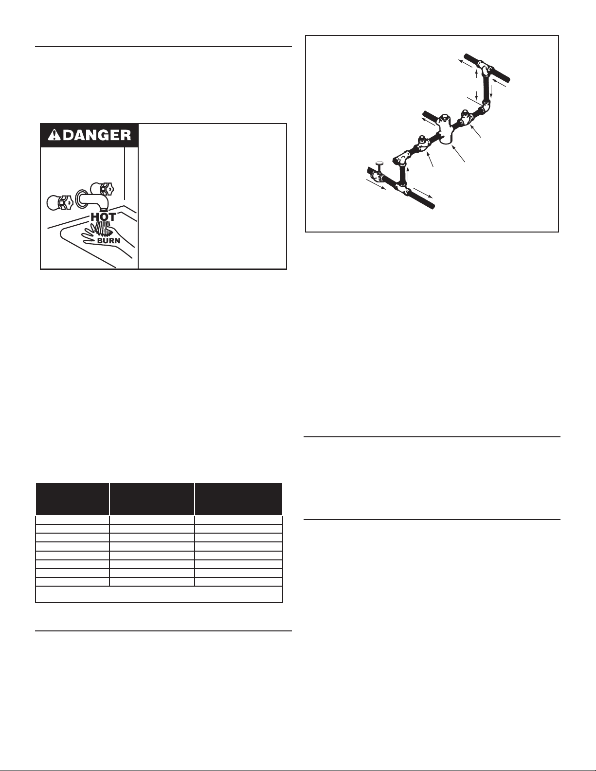
satises the demand of the application, a mixing valve should
be installed at the water heater or at the hot water taps to further
reduce system water temperature. See
Figure 10
(page 14).
Mixing valves are available at plumbing supply stores. Consult
a Qualied Installer or Service Agency. Follow mixing valve
manufacturer’s instructions for installation of the valves.
Table 5. BURN TIME AT VARIOUS TEMPERATURES
Time for Permanent
Water Temperature
°F (°C)
110 (43) (normal shower temp.)
116 (47) (pain threshold)
116 (47) 35 minutes 45 minutes
122 (50) 1 minute 5 minutes
131 (55) 5 seconds 25 seconds
140 (60) 2 seconds 5 seconds
149 (65) 1 second 2 seconds
154 (68) instantaneous 1 second
(U.S. Government Memorandum, C.P.S.C., Peter L. Armstrong, Sept. 15,
1978)
Time for 1st Degree Burn
(Less Severe Burns)
Burns
2nd & 3rd Degree
(Most Severe Burns)
DISH-WASHING MACHINES
COLD
WATER
INLET
CHECK
VALV E
TO TANK
INLET
Figure 10. Mixing Valve
CHECK
VALV E
MIXING
VALV E
The National Sanitation Foundation also recommends circulation
of 180°F (82°C) water. The circulation should be just enough to
provide 180°F (82°C) water at the point of take-off to the dishwashing machine.
Adjust ow by throttling a full port ball valve installed in the
circulating line on the outlet side of the pump. Never throttle
ow on the suction side of a pump. See the
Water Piping Diagrams
(page 43).
Note: These water heaters meet the NSF Standard 5 for
sanitary installations when used with the leg kit part
number 100109227.
CLOSED WATER SYSTEMS
Water supply systems may, because of code requirements
or such conditions as high line pressure, among others, have
installed devices such as pressure reducing valves, check valves,
and back ow preventers. Devices such as these cause the water
system to be a closed system.
THERMAL EXPANSION
As water is heated, it expands (thermal expansion). In a closed
system the volume of water will grow when it is heated. As the
volume of water grows there will be a corresponding increase in
water pressure due to thermal expansion. Thermal expansion can
cause premature tank failure (leakage). This type of failure is not
covered under the limited warranty. Thermal expansion can also
cause intermittent Temperature-Pressure Relief Valve operation:
water discharged from the valve due to excessive pressure build
up. This condition is not covered under the limited warranty.
All dish-washing machines meeting the National Sanitation
Foundation requirements are designed to operate with water ow
pressures between 15 and 25 pounds per square inch (103 kPa
and 173 kPa). Flow pressures above 25 pounds per square inch
(173 kPa), or below 15 pounds per square inch (103 kPa), will
result in improperly sanitized dishes. Where pressures are high,
a water pressure reducing or ow regulating control valve should
be used in the 180°F (82°C) line to the dish-washing machine and
should be adjusted to deliver water pressure between these limits.
The Temperature-Pressure Relief Valve is not intended for the
constant relief of thermal expansion.
A properly sized and pressurized thermal expansion tank must
be installed on all closed systems to control the harmful effects
of thermal expansion. Contact a local plumbing service agency
to have a thermal expansion tank installed.
14
Page 15
See
Water Line Connections
(page 23) and the
Water Piping Diagrams
(page 43).
TEMPERATURE-PRESSURE RELIEF VALVE
Explosion Hazard
Temperature-Pressure Relief Valve
must comply with ANSI Z21.22CSA 4.4 and ASME code.
Properly sized temperaturepressure relief valve must be
installed in opening provided.
Can result in overheating and
excessive tank pressure.
Can cause serious injury or death.
This water heater is provided with a properly rated/sized and
certied combination Temperature-Pressure Relief Valve (T&P
valve) by the manufacturer. The valve is certied by a nationally
recognized testing laboratory that maintains periodic inspection
of production of listed equipment of materials as meeting the
requirements for
•
CSA 4.4
, and the code requirements of
Relief Valves for Hot Water Supply Systems, ANSI Z21.22
ASME
.
If replaced, the new T&P valve must meet the requirements
of local codes, but not less than a combination TemperaturePressure Relief Valve rated/sized and certied as indicated in
the above paragraph. The new valve must be marked with a
maximum set pressure not to exceed the marked hydrostatic
working pressure of the water heater (150 psi = 1,035 kPa) and
a discharge capacity not less than the water heater Btu/hr or kW
input rate as shown on the water heater’s model rating label.
Note: In addition to the factory installed Temperature-
Pressure Relief Valve on the water heater, each remote
storage tank that may be installed and piped to a water
heating appliance must also have its own properly
sized, rated and approved Temperature-Pressure
Relief Valve installed. Contact your local distributor or
contact Technical Support for assistance in sizing a
Temperature-Pressure Relief Valve for remote storage
tanks. See the contact information label on the water
heater.
For safe operation of the water heater, the Temperature-Pressure
Relief Valve must not be removed from its designated opening
nor plugged. The Temperature-Pressure Relief Valve must be
installed directly into the tting of the water heater designed for the
relief valve. Install discharge piping so that any discharge will exit
the pipe within six inches (15.2 cm) above an adequate oor drain,
or external to the building. In cold climates it is recommended
that it be terminated at an adequate drain inside the building. Be
certain that no contact is made with any live electrical part. The
discharge opening must not be blocked or reduced in size under
any circumstances. Excessive length, over 30 feet (9.14 m), or
use of more than four elbows can cause restriction and reduce
the discharge capacity of the valve.
No valve or other obstruction is to be placed between the
Temperature-Pressure Relief Valve and the tank. Do not connect
discharge piping directly to the drain unless a six inches (15.2
cm) air gap is provided. To prevent bodily injury, hazard to life, or
property damage, the relief valve must be allowed to discharge
water in adequate quantities if circumstances demand. If the
discharge pipe is not connected to a drain or other suitable
means, the water ow may cause property damage.
CAUTION
Water Damage Hazard
Temperature-Pressure Relief Valve discharge
•
pipe must terminate at adequate drain.
T&P VALVE DISCHARGE PIPE REQUIREMENTS
• Shall not be smaller in size than the outlet pipe size of the
valve, or have any reducing couplings or other restrictions.
• Shall not be plugged or blocked.
• Shall not be exposed to freezing temperatures.
• Shall be of material listed for hot water distribution.
• Shall be installed so as to allow complete drainage of both the
Temperature-Pressure Relief Valve and the discharge pipe.
• Must terminate a maximum of six inches (15.2 cm) above a
oor drain or external to the building. In cold climates, it is
recommended that the discharge pipe be terminated at an
adequate drain inside the building.
• Shall not have any valve or other obstruction between the
relief valve and the drain.
Water temperature over 125°F (52°C)
can cause severe burns instantly
resulting in severe injury or death.
Children, the elderly and the
physically or mentally disabled are at
highest risk for scald injury.
Feel water before bathing or
showering.
Temperature limiting devices such as
mixing valves must be installed
when required by codes and to
ensure safe temperatures at fixtures.
The Temperature-Pressure Relief Valve must be manually
operated at least twice a year. Caution should be taken to
ensure that (1) no one is in front of or around the outlet of the
Temperature-Pressure Relief Valve discharge line, and (2) the
water manually discharged will not cause any bodily injury or
property damage because the water may be extremely hot. If
after manually operating the valve, it fails to completely reset
and continues to release water, immediately close the cold water
inlet to the water heater, follow the draining instructions in this
manual, and replace the Temperature-Pressure Relief Valve with
a properly rated/sized new one.
15
Page 16

Note: The purpose of a Temperature-Pressure Relief Valve
is to prevent excessive temperatures and pressures in
the storage tank. The T&P valve is not intended for the
constant relief of thermal expansion. A properly sized
thermal expansion tank must be installed on all closed
systems to control thermal expansion. See
Expansion
and
Closed Water Systems
(page 14).
Thermal
If you do not understand these instructions or have any questions
regarding the Temperature-Pressure Relief Valve. Contact your
local distributer or contact Technical Support for assistance. See
the contact information label on the water heater.
CONTAMINATED AIR
Breathing Hazard - Carbon Monoxide Gas
Install water heater in accordance with
the Instruction Manual and NFPA 54.
To avoid injury, combustion and ventilation
air must be taken from outdoors.
Do not place chemical vapor emitting
products near water heater.
Breathing carbon monoxide can cause brain damage or
death. Always read and understand instruction manual.
Corrosion of the ue ways and vent system may occur if air for
combustion contains certain chemical vapors. Such corrosion
may result in failure and risk of asphyxiation.
Breathing Hazard - Carbon Monoxide Gas
Install water heater in accordance with
the Instruction Manual and NFPA 54 or
CAN/CSA-B149.1.
To avoid injury, combustion and ventilation
air must be taken from outdoors.
Do not place chemical vapor emitting
products near water heater.
Breathing carbon monoxide can cause brain damage or
death. Always read and understand instruction manual.
Combustion air that is contaminated can greatly diminish the life
span of the water heater and water heater components such as
igniters and burners. Propellants of aerosol sprays, beauty shop
supplies, water softener chemicals and chemicals used in dry
cleaning processes that are present in the combustion, ventilation
or ambient air can cause such damage.
Do not store products of this sort near the water heater. Air which
is brought in contact with the water heater should not contain any
of these chemicals. If necessary, uncontaminated air should be
obtained from remote or outdoor sources. The limited warranty
is voided when failure of water heater is due to a corrosive
atmosphere.
AIR REQUIREMENTS
For safe operation an adequate supply of fresh uncontaminated
air for combustion and ventilation must be provided.
Do not install the water heater in a conned space unless an
adequate supply of air for combustion and ventilation is brought
in to that space using the methods described in
Confined Space
(page 16).
Never obstruct the ow of ventilation air. If you have any doubts
or questions at all, call your gas supplier. Failure to provide the
proper amount of combustion air can result in a re or explosion
and cause property damage, serious bodily injury or death.
UNCONFINED SPACE
An Unconned Space is one whose volume IS NOT LESS THAN
50 cubic feet per 1,000 Btu/hr (4.8 cubic meters per kW) of the
total input rating of all appliances installed in the space. Rooms
communicating directly with the space, in which the appliances
are installed, through openings not furnished with doors, are
considered a part of the unconned space.
Makeup air requirements for the operation of exhaust fans,
kitchen ventilation systems, clothes dryers and replaces shall
also be considered in determining the adequacy of a space to
provide combustion, ventilation and dilution air.
UNUSUALLY TIGHT CONSTRUCTION
In unconned spaces in buildings, inltration may be adequate to
provide air for combustion, ventilation and dilution of ue gases.
However, in buildings of unusually tight construction (for example,
weather stripping, heavily insulated, caulked, vapor barrier, etc.),
additional air must be provided using the methods described in
Confined Space
CONFINED SPACE
(page 16).
A conned space is one whose volume IS LESS THAN 50 cubic
feet per 1,000 Btu/hr (4.8 cm per kW) of the total input rating of
all appliances installed in the space.
An insufcient supply of air can cause recirculation of combustion
products resulting in contamination that may be hazardous to life.
Such a condition often will result in a yellow, luminous burner
ame, causing sooting of the combustion chamber, burners and
ue tubes and creates a risk of asphyxiation.
Openings must be installed to provide fresh air for combustion,
ventilation and dilution in conned spaces. The required size for
the openings is dependent on the method used to provide fresh
air to the conned space AND the total Btu/hr input rating of all
appliances installed in the space.
16
Page 17

DIRECT VENT APPLIANCES
Appliances installed in a Direct Vent conguration that derive all
air for combustion from the outdoor atmosphere through sealed
intake air piping are not factored in the total appliance input Btu/
hr calculations used to determine the size of openings providing
fresh air into conned spaces.
EXHAUST FANS
Where exhaust fans are installed, additional air shall be provided
to replace the exhausted air. When an exhaust fan is installed in
the same space with a water heater, sufcient openings to provide
fresh air must be provided that accommodate the requirements
for all appliances in the room and the exhaust fan. Undersized
openings will cause air to be drawn into the room through the
water heater’s vent system causing poor combustion. Sooting,
serious damage to the water heater, and the risk of re or
explosion may result. It can also create a risk of asphyxiation.
LOUVERS AND GRILLES
The free areas of the fresh air openings in the instructions that
follow do not take in to account the presence of louvers, grilles
or screens in the openings.
The required size of openings for combustion, ventilation and
dilution air shall be based on the “net free area” of each opening.
Where the free area through a design of louver or grille or screen
is known, it shall be used in calculating the size of opening
required to provide the free area specied. Where the louver and
grille design and free area are not known, it shall be assumed
that wood louvers will have 25% free area and metal louvers
and grilles will have 75% free area. Non motorized louvers and
grilles shall be xed in the open position.
17
Page 18

VENTING INSTALLATION
VENTING
THE INSTRUCTIONS IN THIS SECTION ON VENTING MUST
BE FOLLOWED TO AVOID CHOKED COMBUSTION OR
RECIRCULATION OF FLUE GASES. SUCH CONDITIONS
CAUSE SOOTING OR RISKS OF FIRE AND ASPHYXIATION.
Heater must be protected from freezing downdrafts.
Remove all soot or other obstructions from the chimney that will
retard a free draft.
Water heaters covered by these instructions are Category I,
Natural Draft appliances. Type B venting is recommended with
this heater. For typical venting application see
This water heater must be vented in compliance with all local
codes, the current revision of the
and with the
If any part of the vent system are exposed to ambient temperatures
below 40°F it must be insulated to prevent condensation.
• Do not connect the heater to a common vent or chimney with
solid fuel burning equipment. This practice is prohibited by
many local building codes as is the practice of venting gas
red equipment to the duct work of ventilation systems.
Category I Natural Draft Venting Tables
National Fuel Gas Code (ANSI-Z223.1)
Table 6
.
(page 21).
The venting must comply with the current editions of the
Fuel Gas Code, ANSI Z223.1/NFPA 54
Figure 11. Correct Vent Pipe Installation
Figure 12. Incorrect Vent Pipe Installation
.
National
• Where a separate vent connection is not available and the
vent pipe from the heater must be connected to a common
vent with an oil burning furnace, the vent pipe should enter
the smaller common vent or chimney at a point above the
large vent pipe.
18
Page 19
MULTIPLE HEATER MANIFOLD
Table 6
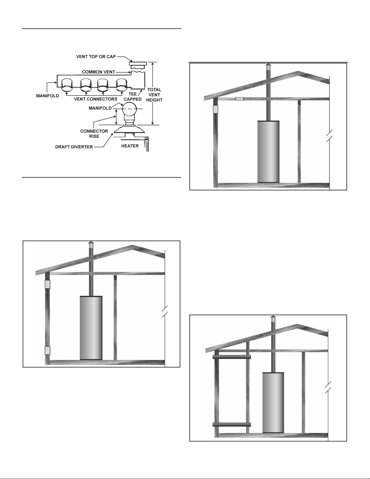
(page 21) should be used for horizontally manifolding
two or more heaters.
Figure 13. Common Venting Multiple Water Heaters
FRESH AIR OPENINGS FOR CONFINED SPACES
The following instructions shall be used to calculate the size,
number and placement of openings providing fresh air for
combustion, ventilation and dilution in conned spaces. The
illustrations shown in this section of the manual are a reference for
the openings that provide fresh air into conned spaces only. DO
NOT refer to these illustrations for the purpose of vent installation.
See
Venting Installation
OUTDOOR AIR THROUGH TWO OPENINGS
for venting installation instructions.
Each opening shall have a minimum free area of 1 square inch
per 4,000 Btu/hr (550 mm2 per kW) of the aggregate input rating
of all appliances installed in the enclosure. Each opening shall
not be less than 100 square inches (645 cm2).
OUTDOOR AIR THROUGH ONE OPENING
Figure 15. Outdoor Air Through One Opening
Alternatively a single permanent opening, commencing within 12
inches (300 mm) of the top of the enclosure, shall be provided.
See
Figure 15
. The water heater shall have clearances of at least
1 inch (25 mm) from the sides and back and 6 inches (150 mm)
from the front of the water heater. The opening shall directly
communicate with the outdoors or shall communicate through a
vertical or horizontal duct to the outdoors or spaces that freely
communicate with the outdoors and shall have a minimum free
area of the following:
Figure 14. Outdoor Air Through Two Openings
The conned space shall be provided with two permanent
openings, one commencing within 12 inches (300 mm) of the top
and one commencing within 12 inches (300 mm) of the bottom
of the enclosure. The openings shall communicate directly with
the outdoors. See
Figure 14
.
1. One square inch per 3000 Btu/hr (733 mm2 per kW) of the
total input rating of all appliances located in the enclosure
2. Not less than the sum of the areas of all vent connectors in
the space
OUTDOOR AIR THROUGH TWO HORIZONTAL DUCTS
Figure 16. Two Horizontal Ducts
19
Page 20
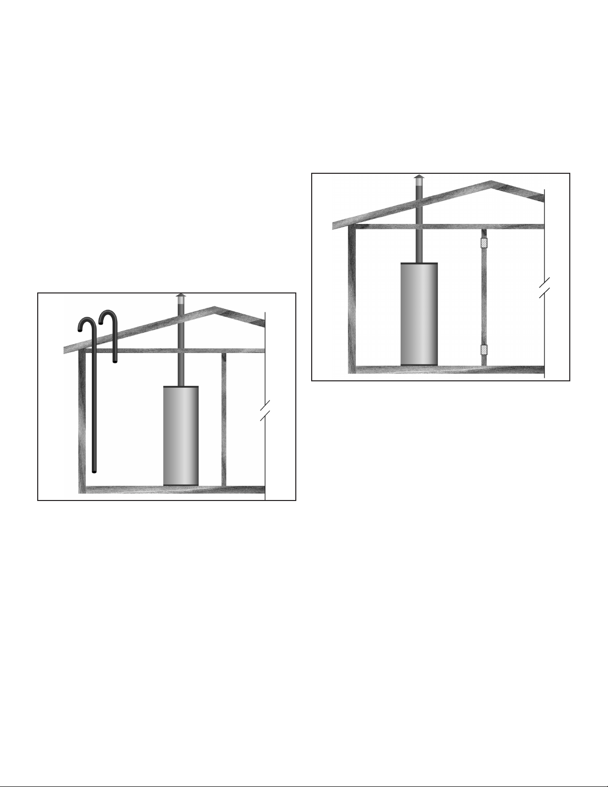
The conned space shall be provided with two permanent
horizontal ducts, one commencing within 12 inches (300 mm) of
the top and one commencing within 12 inches (300 mm) of the
bottom of the enclosure. The horizontal ducts shall communicate
directly with the outdoors. See
Figure 16
.
Each duct opening shall have a minimum free area of 1 square
inch per 2,000 Btu/hr (1100 mm2 per kW) of the aggregate input
rating of all appliances installed in the enclosure.
When ducts are used, they shall be of the same cross sectional
area as the free area of the openings to which they connect.
The minimum dimension of rectangular air ducts shall be not
less than 3 inches.
OUTDOOR AIR THROUGH TWO VERTICAL DUCTS
The illustrations shown in this section of the manual are a
reference for the openings that provide fresh air into conned
spaces only.
DO NOT refer to these illustrations for the purpose of vent
installation. See
Venting Installation
(page 18) for venting
installation instructions.
of the enclosure. The vertical ducts shall communicate directly
with the outdoors. See
Figure 17
.
Each duct opening shall have a minimum free area of 1 square
inch per 4,000 Btu/hr (550 mm2 per kW) of the aggregate input
rating of all appliances installed in the enclosure.
When ducts are used, they shall be of the same cross sectional
area as the free area of the openings to which they connect. The
minimum dimension of rectangular air ducts shall be not less
than 3 inches (7.62 cm).
AIR FROM OTHER INDOOR SPACES
Figure 17. Two Vertical Ducts
The conned space shall be provided with two permanent vertical
ducts, one commencing within 12 inches (300 mm) of the top
and one commencing within 12 inches (300 mm) of the bottom
Figure 18. Two Permanent Openings
The conned space shall be provided with two permanent
openings, one commencing within 12 inches (300 mm) of the top
and one commencing within 12 inches (300 mm) of the bottom
of the enclosure. See
Figure 18
.
Each opening shall communicate directly with an additional
room(s) of sufcient volume so that the combined volume of all
spaces meets the criteria for an Unconned Space.
Each opening shall have a minimum free area of 1 square inch
per 1,000 Btu/hr (2200 mm2 per kW) of the aggregate input rating
of all appliances installed in the enclosure. Each opening shall
not be less than 100 square inches (645 cm2).
20
Page 21
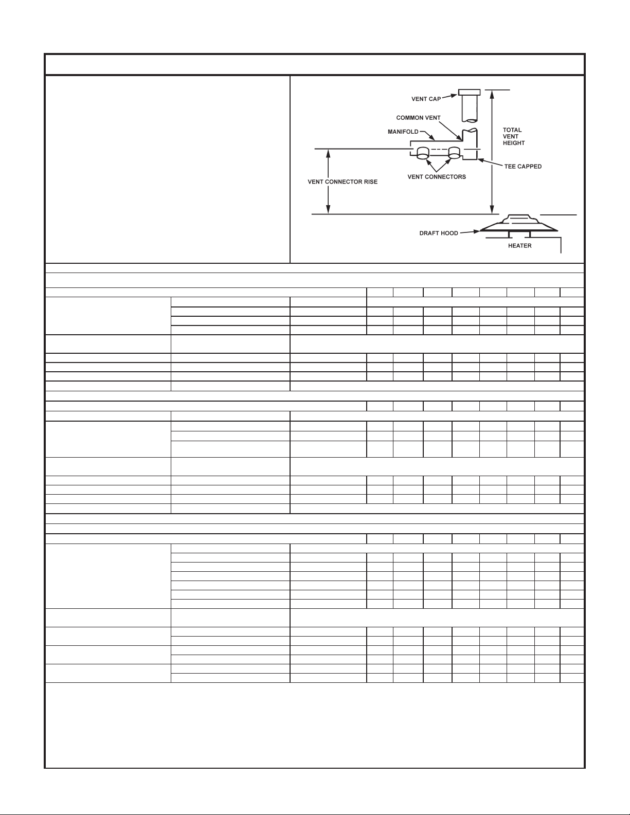
Table 6. Technical Data Venting
TYPE B GAS VENT
Multiple Gas Fired Tank-Type Heaters
When venting multiple tank type heaters using Type B
vent pipe, follow the installation diagram (gure 13) and
tables below which give sizing and data based upon
54/ANSI Z223. 1992
MODEL 120
Input: 120,000 Btuh Total Vent Height (Feet)
Draft Hood: 5” 6 8 10 15 20 30 50 100
Number of Heaters
MODEL 154
Input: 154,000 Btuh Total Vent Height (Feet)
Draft Hood: 6” 6 8 10 15 20 30 50 100
Numbers of Heaters
.
Input Btuh Rise
120,000 1 Ft. 7 7 7 6 6 6 6 6
120,000 2 Ft. 6 6 6 6 6 6 6 5
120,000 3 Ft. 6 6 6 6 6 5 5 5
Combined Input in
Thousands of Btuh
2 240 10 8 8 7 7 7 6 7
3 360 10 10 10 10 8 8 7 7
4 480 12 12 12 10 10 10 8 8
Input Btuh Rise Vent Connector Diameter (in inches)
154,000 1 Ft. 8 8 7 7 7 7 7 7
154,000 2 Ft. 7 7 7 7 7 6 6 6
154,000 3 Ft. 7 7 7 6 6 6 6 6
Combined Input in
Thousands of Btuh
2 308 10 10 10 8 8 7 7 7
3 462 12 12 12 10 10 10 8 8
4 616 14 14 12 12 12 10 1 10
NFPA
Vent Connector Diameter (inches)
Manifold and Common Vent Diameter (In inches)
Manifold and Common Vent Diameter (in inches)
MODEL 180, 197, 199, 200
Input: 180,000, 199,000 Btuh Total Vent Height (Feet)
Number of Heaters
2
3
4
Draft Hood: 6” 6 8 10 15 20 30 50 100
Input Btuh Rise Vent Connector Diameter (in inches)
180,000 1 Ft. 8 8 8 8 8 7 7 7
199,000 - - 8 8 8 8 8 7
180,000 2 Ft. 8 8 7 7 7 7 7 7
199,000 8 8 8 8 7 7 7 7
180,000 3 Ft. 7 7 7 7 7 7 6 6
199,000 8 8 7 7 7 7 7 6
Combined Input in
Thousands of Btuh
360 10 10 10 10 8 8 7 7
398 12 10 10 10 10 8 8 7
540 14 12 12 12 10 10 10 8
597 14 14 12 12 12 10 10 10
720 14 14 14 12 12 12 10 10
796 16 14 14 14 12 12 12 10
21
Manifold & Common Vent Diameter
Page 22
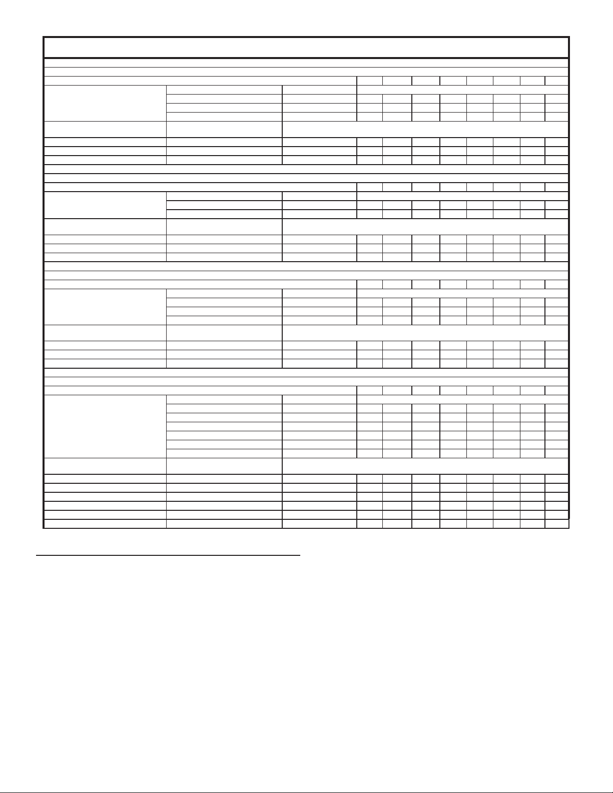
Table 6. Technical Data Venting
MODEL 250, 251
Input: 250,000/251,000 Btuh Total Vent Height (Feet)
Draft Hood: 6” 6 8 10 15 20 30 50 100
Number of Heaters
2 500/502 14 12 12 10 10 10 10 8
3 750/753 16 14 14 14 12 12 10 10
4 1000/1004 18 16 16 14 14 14 12 12
MODEL 275
Input: 275,000 Btuh Total Vent Height (Feet)
Draft Hood: 6” 6 8 10 15 20 30 50 100
Number of Heaters
2 500/502 14 12 12 10 10 10 10 8
3 750/753 16 14 14 14 12 12 10 10
4 1000/1004 18 16 16 14 14 14 12 12
MODEL 305
Input: 305,000 Btuh Total Vent Height (Feet)
Draft Hood: 8” 6 8 10 15 20 30 50 100
Number of Heaters
2 610 14 14 12 12 12 10 10 10
3 915 16 16 16 14 14 12 12 12
4 1220 18 18 16 16 16 14 14 12
MODEL 365, 400
Input: 365,000, 399,000 Btuh Total Vent Height (Feet)
Draft Hood: 8” 6 8 10 15 20 30 50 100
Number of Heaters
2 730 14 14 14 12 12 12 10 10
3 1095 18 18 16
4 1460
Input Btuh Rise Vent Connector Diameter (inches)
250/251,000 1 Ft. - - - - - - 8 8
250/251,000 2 Ft. - - - 8 8 8 8 8
250/251,000 3 Ft. - 8 8 8 8 8 7 7
Combined Input in
Thousands of Btuh
Input Btuh Rise Vent Connector Diameter (inches)
275,000 2 Ft. - - - - - 8 8 8
275,000 3 Ft. - - - 8 8 8 8 8
Combined Input in
Thousands of Btuh
Input Btuh Rise Vent Connector Diameter (inches)
305,000 1 Ft. - - 10 10 10 10 10 10
305,000 2 Ft. 10 10 10 10 10 10 8 8
305,000 3 Ft. 10 10 10 10 10 8 8 8
Combined Input in
Thousands of Btuh
Input Btuh Rise Vent Connector Diameter (inches)
365,000 1 Ft. - - - - - 10 10 10
399,000 - - - - - - 10 10
365,000 2 Ft. 12 12 10 10 10 10 10 10
399,000 12 12 12 12 10 10 10 10
365,000 3 Ft. 10 10 10 10 10 10 10 10
399,000 12 10 10 10 10 10 10 10
Combined Input in
Thousands of Btuh
798 16 14 14 14 12 12 10 10
1197
1596 22 20 20
Manifold and Common Vent Diameter (In inches)
Manifold and Common Vent Diameter (In inches)
Manifold and Common Vent Diameter (In inches)
Manifold and Common Vent Diameter (In inches)
16
18 18
20 20
18
18
14 14 12 12
16 14
16
18 16
18
18 16 14 14
16
14
14
12
12
MECHANICAL VENTING
SINGLE UNIT INSTALLATION
When mechanical venting of this heater is desired, the following
kit is available.
A. O. Smith part number 100110445
Where an approved power venter is to be installed to operate in
conjunction with the water heater thermostat, the following codes
must be adhered to. Field wiring should conform to the current
edition of the
National Electrical Code NFPA 70
and/or local codes.
VENT INSTALLATION
Seal all joints between the power venter and the vent termination.
This is to prevent leakage of exhaust products into the room(s)
due to positive pressure of blower.
The “Sequence of Operation” description will be the same with
mechanical venting except;
• When the water heater thermostat calls for heat:
Thermostat contacts “Close” and the power venter blower
(120 VAC) is energized. Sufcient draft must be established
for the “Draft Prover Switch (N.O.)” to “Close”. When the
draft prover switch “Closes” the relay coil of the ue damper
is energized.
MULTIPLE UNIT INSTALLATION
For multiple unit installations, contact A. O. Smith, Technical
Support Center at 1-800-527-1953.
22
Page 23
WATER HEATER INSTALLATION
WATER LINE CONNECTIONS
The water piping installation must conform to these instructions
and to all local code authority having jurisdiction. Good practice
requires that all heavy piping be supported.
Read and observe all requirements in the following sections
before installation of the water piping begins:
•
Water Temperature Control and Mixing Valves
•
Dish-washing Machines
•
Temperature-Pressure Relief Valve
•
Closed Water Systems
• For multiple water heater installations, see
Diagrams
WATER (POTABLE) HEATING AND SPACE HEATING
All piping components connected to this unit for space heating
applications shall be suitable for use with potable water.
Toxic chemicals, such as those used for boiler treatment, shall
NEVER be introduced into this system.
This unit may NEVER be connected to any existing heating
system or component(s) previously used with a non-potable
water heating appliance.
When the system requires water for space heating at temperatures
higher than required for domestic water purposes, a tempering
valve must be installed. Please refer to
43) for suggested piping arrangements.
(page 43).
(page 14).
and
(page 15).
Thermal Expansion
(page 14).
(page 14).
Water Piping
Water Piping Diagrams
(page
T&P VALVE DISCHARGE PIPE
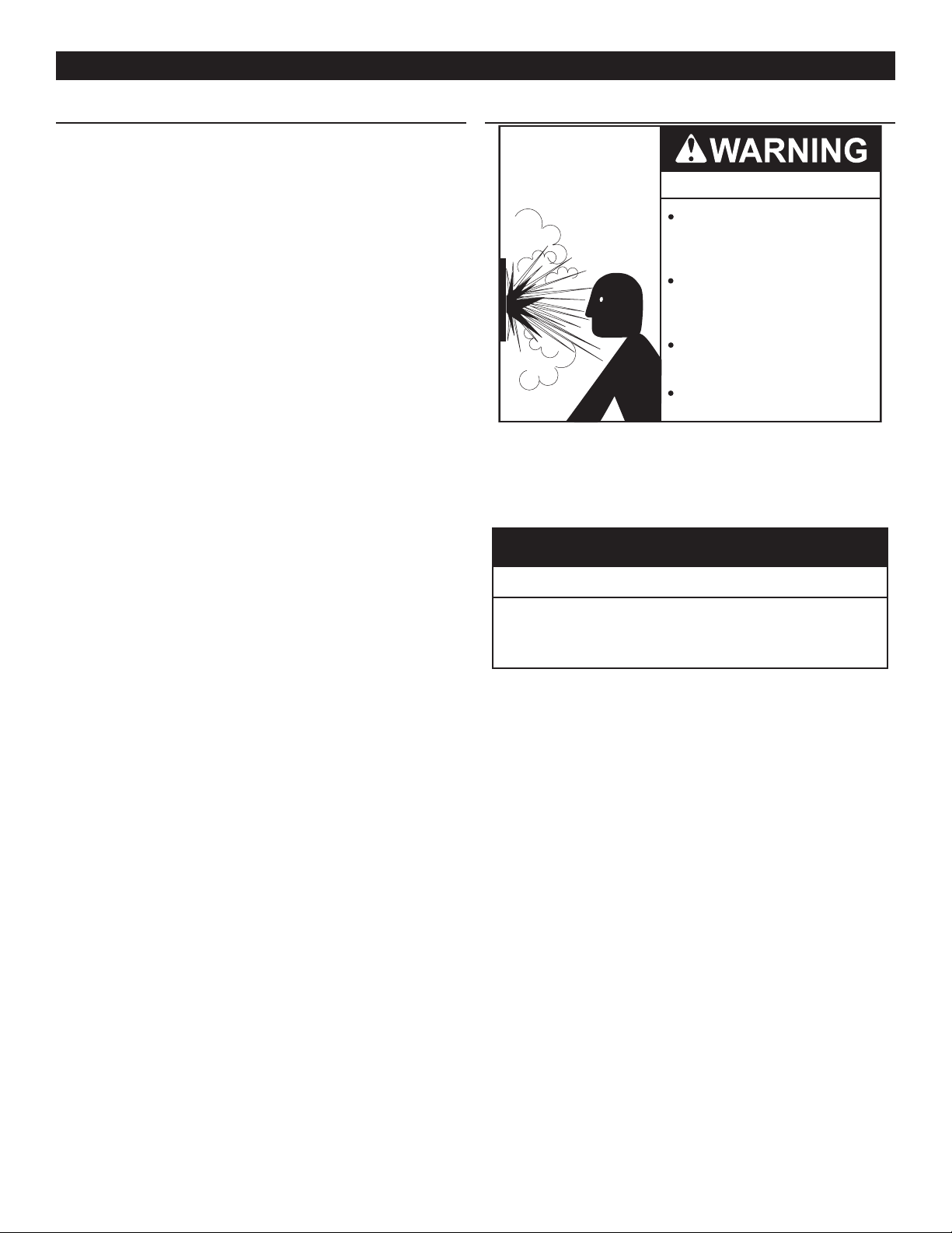
Explosion Hazard
Temperature-Pressure Relief Valve
must comply with ANSI Z21.22CSA 4.4 and ASME code.
Properly sized temperaturepressure relief valve must be
installed in opening provided.
Can result in overheating and
excessive tank pressure.
Can cause serious injury or death.
This water heater is provided with a properly rated/sized and
certied combination temperature - pressure (T&P) relief valve
by the manufacturer. See
15) for information on replacement and other requirements.
Temperature-Pressure Relief Valve
(page
CAUTION
Water Damage Hazard
These water heaters cannot be used in space heating
applications only
THERMOMETERS (NOT SUPPLIED)
Thermometers should be obtained and eld installed as shown
in the installation diagrams.
Thermometers are installed in the system as a means of detecting
the temperature of the outlet water supply.
WATER PIPING DIAGRAMS
This manual provides detailed water piping diagrams for typical
methods of application for the water heaters. See
Diagrams
The water heater may be installed by itself, or with a separate
storage tank. When used with a separate storage tank, the
circulation may be either by gravity or by means of circulating
pump. Adjust ow by throttling a full port ball valve installed in
the circulating line on the outlet side of the pump. Never throttle
ow on the suction side of a pump. See
(page 43).
Note: In addition to the factory installed Temperature-Pressure
(page 43) .
Water Piping Diagrams
Relief Valve (T&P valve) on the water heater, each
remote storage tank that may be installed and piped to a
water heating appliance must also have its own properly
sized, rated and approved Temperature-Pressure Relief
Valve installed.
Water Piping
Temperature-Pressure Relief Valve discharge
•
pipe must terminate at adequate drain.
Install a discharge pipe between the T&P valve discharge opening
and a suitable oor drain. Do not connect discharge piping directly
to the drain unless a 6” (15.2 cm) air gap is provided. To prevent
bodily injury, hazard to life, or property damage, the relief valve
must be allowed to discharge water in adequate quantities should
circumstances demand. If the discharge pipe is not connected
to a drain or other suitable means, the water ow may cause
property damage.
T&P VALVE DISCHARGE PIPE REQUIREMENTS:
• Shall not be smaller in size than the outlet pipe size of the
valve, or have any reducing couplings or other restrictions.
• Shall not be plugged or blocked.
• Shall not be exposed to freezing temperatures.
• Shall be of material listed for hot water distribution.
• Shall be installed so as to allow complete drainage of both
Temperature-Pressure Relief Valve and the discharge pipe.
• Must terminate a maximum of six inches above a oor drain
or external to the building. In cold climates, it is recommended
that the discharge pipe be terminated at an adequate drain
inside the building.
• Shall not have any valve or other obstruction between the
relief valve and the drain.
Call the toll free technical support phone number listed on the
back cover of this manual for further assistance in sizing a T&P
valve for remote storage tanks.
23
Page 24
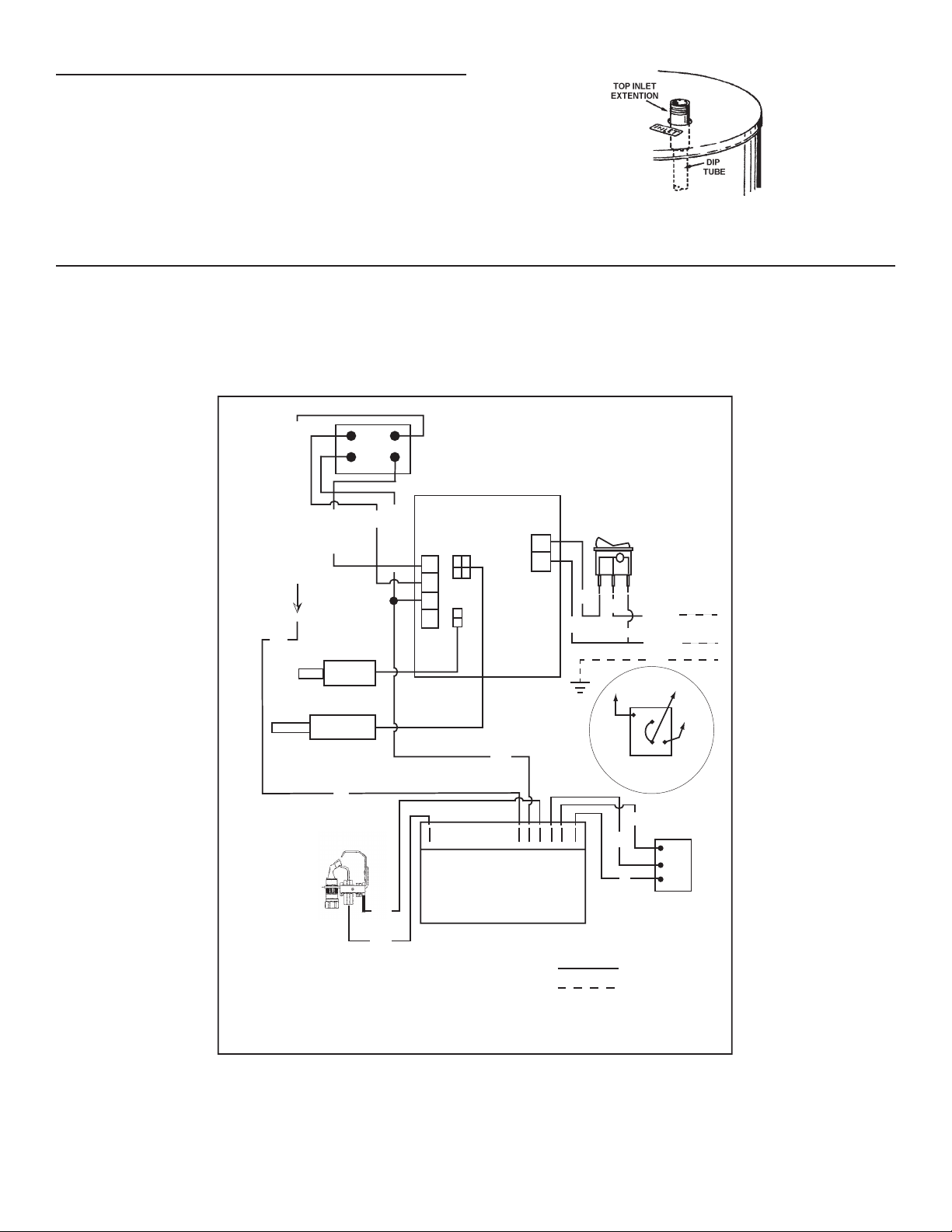
INSTALLATION DIAGRAMS - TOP INLET/OUTLET USAGE
Use of the top inlet water connection requires an inlet dip tube
(refer to gure 19). The tube is supplied in the heater. Follow
caution labels if applying heat to this tting. Do not allow pipe
dope to contact the plastic tube during installation.
WATER HEATER WIRING
Figure 19. Tube Inlet Installation
All electrical work must be installed in accordance with the
current edition of the
National Electrical Code ANSI/NFPA No. 70
and
must conform to all local code authority having jurisdiction. AN
ELECTRICAL GROUND IS REQUIRED TO REDUCE RISK OF
ELECTRICAL SHOCK OR POSSIBLE ELECTROCUTION.
24 VAC TO IGNITION CONTROL
R
24 VAC
DRIVE
Y
LOWER
PROBE
UPPER
PROBE/ECO
R
13
42
BLK
DAMPER
DAMPER
DRIVE
24 NEUTRAL
4
3
2
1
If any of the original wire as supplied with the water heater must
be replaced, use only type 105°C thermoplastic or equivalent
2500C type F must be used for the ame sensor and igniter leads.
The controls of this water heater are polarity sensitive. Be certain
to properly wire the hot and neutral connections.
11E79
LINE
IN
W
W
BLK
ON/OFF
SWITCH
X
BLK
W
PV
120 vac
NEUTRAL
GND
PV
TH
PROPANE
GAS
VALV E
MV/PV
MV
MV
TR
BL
BLK
MV
MV/PV
PV
24 V GND
SPARKER
LEGEND:
W--WHITE
BLK--BLACK
BL--BLUE
R--RED
Y--YELLOW
IF ANY OF THE ORIGINAL WIRE AS SUPPLIED MUST BE REPLACED, USE ONLY TYPE 105O C
THERMOPLASTIC OR EQUIVALENT. FLAME SENSOR IGNITION CABLE MUST BE 250O C TYPE F.
W
W
24 V
GND-BURNER
HONEYWELL IGNITION
C
P
Y
M
NATURAL
GAS
VALV E
FACTORY WIRED
BY INSTALLER
330548-000 REV 00
Figure 20. Wiring Diagram
24
Page 25
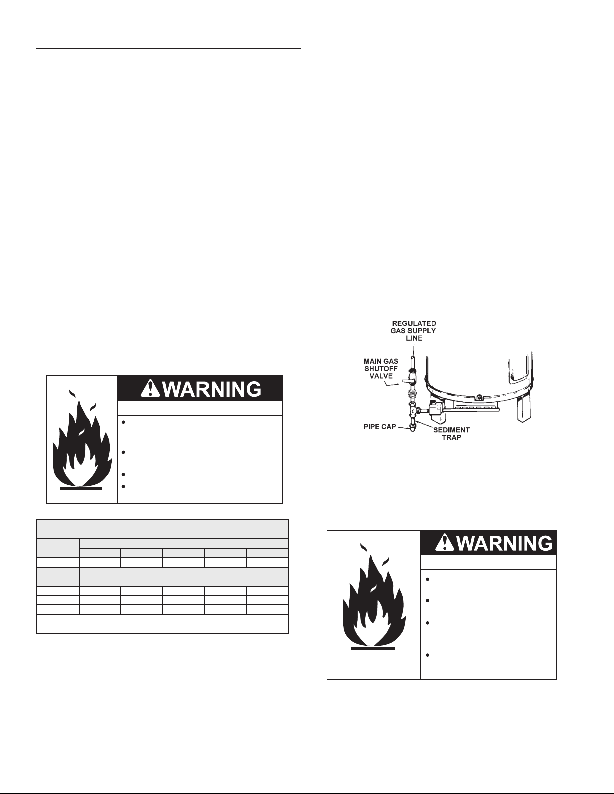
SUPPLY GAS LINE INSTALLATION
Contact your local gas service company to ensure that adequate
gas service is available and to review applicable installation
codes for your area.
Size the main gas line in accordance with
Table 7
. The gures
shown are for straight lengths of pipe at 0.5 in. W.C. pressure
drop, which is considered normal for low pressure systems. Note:
Fittings such as elbows, tees and line regulators will add to the
pipe pressure drop. Also refer to the latest version of the
Fuel Gas Code ANSI Z223.1 / NFPA 54
.
National
Schedule 40 Steel or Wrought Iron Pipe is the preferred material
for the gas line of this water heater. It is imperative to follow the
sizing recommendations in the latest version of the
Gas Code
if Corrugated Stainless Steel Tubing (CSST) is used as
National Fuel
the gas line for this water heater.
The heater is not intended for operation at higher than 14.0"
W.C.- natural gas, (1/2 pound per square inch gage) supply
gas pressure. Exposure to higher supply pressure may cause
damage to the gas valve which could result in re or explosion.
If overpressure has occurred such as through improper testing
of gas lines or emergency malfunction of the supply system, the
gas valve must be checked for safe operation. Make sure that
the outside vents on the supply regulators and the safety vent
valves are protected against blockage. These are parts of the
gas supply system, not the heater. Vent blockage may occur
during ice storms.
If copper supply lines are used they must be internally tinned and
certied for gas service. Before attaching the gas line, be sure
that all gas pipe is clean on the inside.
To trap any dirt or foreign material in the gas supply line, a
sediment trap must be incorporated in the piping (see
Figure 21
).
The sediment trap must be readily accessible and not subject to
freezing conditions. Install in accordance with recommendations
of serving gas suppliers. Refer to the latest version of the
Fuel Gas Code ANSI Z223.1 / NFPA 54
.
National
To prevent damage, care must be taken not to apply too much
torque when attaching gas supply pipe to gas valve inlet.
Apply joint compounds (pipe dope) sparingly and only to the
male threads of pipe joints. Do not apply compounds to the rst
two threads. Use compounds resistant to the action of liqueed
petroleum gases.
GAS METER SIZE – NATURAL GASES ONLY
Be sure the gas meter has sufcient capacity to supply the full
rated gas input of the water heater as well as the requirements
of all other gas red equipment supplied by the meter. If gas
meter is too small, ask the gas company to install a larger meter
having adequate capacity.
Fire and Explosion Hazard
Do not use water heater with any gas
other than the gas shown on the rating
label.
Excessive gas pressure to gas valve can
cause serious injury or death.
Turn off gas lines during installation.
Contact a qualified installer or service
agency for installation and service.
Table 7. Gas Supply Pipe Lengths (in feet)
(Maximum Equivalent Pipe Length - Natural Gas Only)
Input rate
(BTU/hr)
154,000 10 40 150 200 200
Fitting
Type*
45°Ell 0.7 1.0 1.2 1.6 1.9
90°Ell 1.6 2.1 2.6 3.5 4.0
Tee 3.1 4.1 5.2 6.9 8.0
*Screwed Fittings
Natural Gas 0.60 Specic Gravity, 0.50" W.C. Pressure Drop
Schedule 40 Steel or Wrought Iron Pipe
1/2" 3/4" 1" 1 1/4" 1 1/2"
Equivalent length in feet
It is important to guard against gas valve fouling from
contaminants in gas ways. Such fouling may cause improper
operation, re or explosion.
Figure 21. Gas Piping And Sediment Trap Installation
Gas Line Leak Testing
Any time work is done on the gas supply system perform a leak
test to avoid the possibility of re or explosion.
Fire and Explosion Hazard
Use joint compound or Teflon tape
compatible with propane gas.
Leak test gas connections before
placing water heater in operation.
Disconnect gas piping at main
gas shutoff valve before leak
testing heater.
Install sediment trap in
accordance with NFPA 54.
25
Page 26

1. For test pressures exceeding 1/2 psi (3.45 kPa), disconnect
the water heater and its Main Gas Shutoff Valve from the
gas supply piping system during testing. See
Figure 21
. The
gas supply line must be capped when disconnected from the
water heater.
2. For test pressures of 1/2 psi (3.45 kpa) or less, the water
heater need not be disconnected, but must be isolated from
the supply gas line by closing the Main Gas Shutoff Valve
during testing.
3. Paint all supply gas line joints and connections upstream of
the water heater with a rich soap and water solution to test
for leaks. Bubbles indicate a gas leak. Do not use matches,
candles, ame or other sources of ignition for this purpose.
4. Repair any leaks before placing the water heater in operation.
PURGING
Gas line purging is required with new piping or systems.
Purging should be performed per the current edition of
the
National Fuel Gas Code
.
NFPA 54
26
Page 27
Fire or Explosion Hazard
OPERATION
The water heaters covered by this manual are equipped with
an electronic control system that automatically sequences
the Igniter, the 24 VAC Gas Valve, the Burner ignition, and
ame sensing.
Gas line purging is required with new piping or systems in
which air has entered.
To avoid risk of fire or explosion purge discharge must not
enter into confined areas or spaces where ignition can occur.
The area must be well ventilated and all sources of ignition
must be deactivated or removed.
Read instruction manual before
installing, using or servicing
water heater.
PRIOR TO START UP
Installation and start up of this water heater requires abilities
and skills equivalent to that of a licensed tradesman in the eld
involved. See
Do not place the water heater in operation if any part has been
under water. Immediately call a qualied service technician to
inspect the water heater and to replace any part of the control
system and any gas control which has been under water.
Light the water heater in accordance with the
Label
(page 29) on the water heater and in this manual.
Qualifications
(page 6).
Lighting & Operation
Before attempting start up, thoroughly study and know the exact
Sequence of Operation
Sequence Of Operation Flow Chart,
Be certain that the water heater is full of water, that air is purged
from the gas and water lines and that there are no leaks in the
gas and water lines. Ensure all inlet water valves are open.
FILLING THE WATER HEATER
Follow these steps to ll the water heater prior to start up.
1. Close the heater drain valve.
2. Open a nearby hot water faucet to permit air in system to
escape.
3. Fully open the cold water inlet valve allowing the piping and
water heater to ll with water.
4. Close hot water faucet opened in Step 2 as water starts to ow.
Read
Sequence of Operation
and operating this water heater.
With above conditions satised, start the unit in accordance with
the instructions on the
heater. See
Lighting & Operation Label
. See written
section of this manual prior to lighting
Lighting & Operation Label
Sequence of Operation
Figure 22
(page 29).
(page 28).
attached to the
and the
SEQUENCE OF OPERATION
The following information will describe the Sequence of Operation
for this water heater.
1. Switch power on to unit.
2. Thermostat calls for heat.
3. Ignition Control performs diagnostic self check on system
components.
4. The Ignition Control begins the trial for ignition.
5. The Ignition Control turns on the Spark Igniter and opens the
Pilot Gas Valve.
6. The Ignition Control monitors the Flame Sensor during the
ignition trial period.
7. If the Ignition Control does not sense the pilot ame during
the ignition trial period, the Ignition Control shuts the Pilot Gas
Valve and turns off the Spark Igniter. Depending on the water
heater model, the Ignition Control will either retry the ignition
trial at step 4 or lockout the ignition sequence. If the ignition
sequence is locked out, the power to the unit must be cycled
to restart the Ignition Control.
8. If the pilot ame is proved during the ignition trial period, the
Ignition Control turns off the Spark Ignitor and opens the Main
Gas Valve.
9. The Ignition Control allows a 2 second pilot ame stabilization
period to insure that the pilot ame is not extinguished by the
main burner light-off process.
10. The Ignition Control monitors the Flame Sensor during the
heating cycle. If the ame signal is lost, the Ignition Control
shuts the Main Gas Valve and Pilot Gas Valve and re-starts
the ignition process at step 4.
11. Once the unit is satised, the Ignition Control will shut off the
Main Gas Valve and the Pilot Gas Valve and the unit will be
in standby mode until another call for heat is initiated by the
thermostat.
See the ow chart,
Figure 22
(page 28), for more information.
27
Page 28
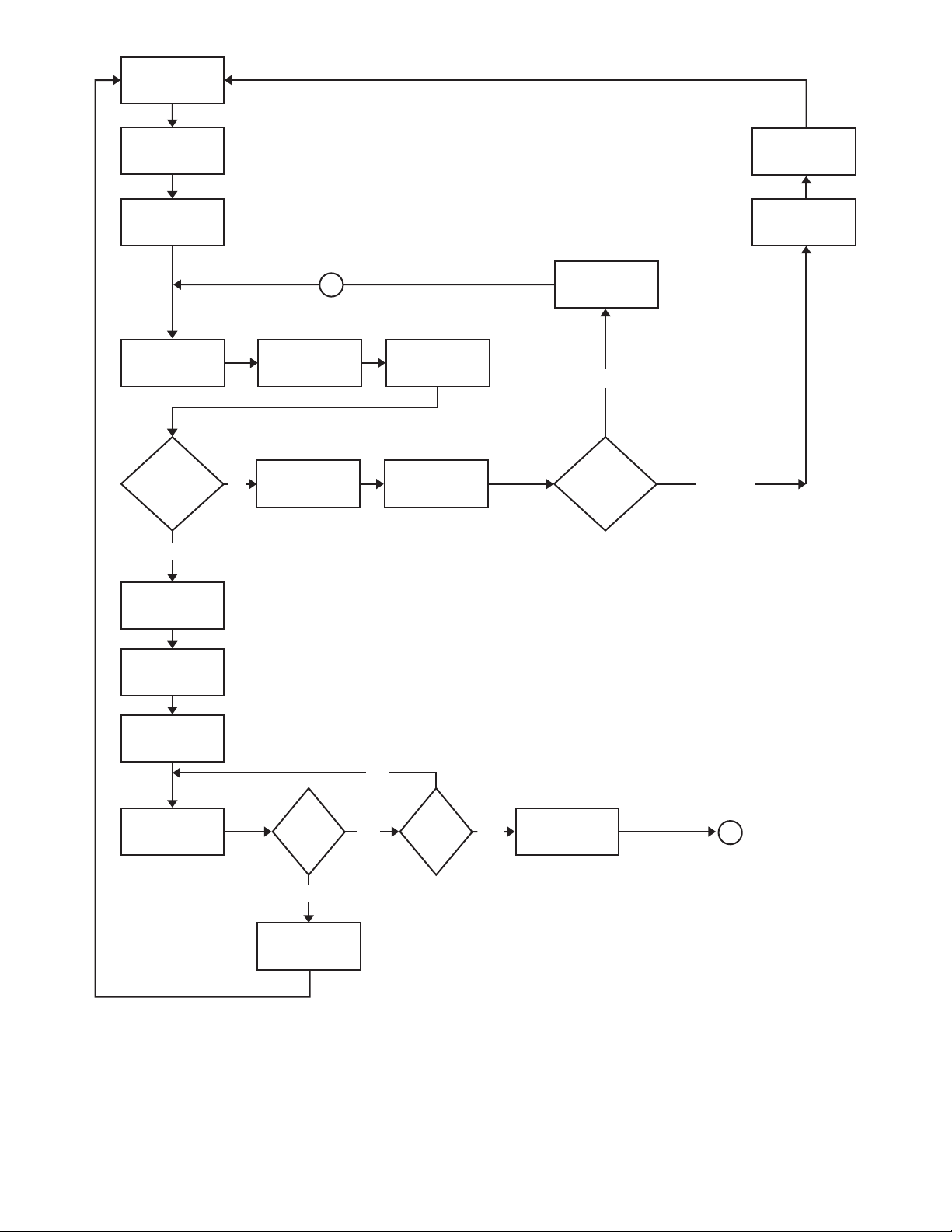
IDLE
(NOT POWERED)
“CALL FOR HEAT”
RECEIVED FROM
THERMOSTAT
POWER TO
MODULE AND
SELF CHECK
TRIAL FOR
IGNITION
(TIMER STARTED)
FLAME
PROVED?
(BEFORE TRIAL FOR IGNITION TIMER EXPIRES)
YES
NO
A
SPARK ON
CLOSE PILOT
GAS VALV E
OPEN PILOT GAS
VALV E
SPARK OFF
RETRY DELAY
(5 MINUTES)
RETRY
RETRY OR
LOCKOUT
MODEL?
WAIT FOR
“CALL FOR HEAT”
TO BE REMOVED
ACTIVATE ALARM
CONTACT(S)
(OPTIONAL)
LOCKOUT
SPARK OFF
OPEN MAIN GAS
VALV E
FLAME
STABILIZATION
(2 SECONDS)
“CALL
RUN
FOR HEAT”
ENDS?
YES
CLOSE MAIN GAS
VALVE AND PILOT
GAS VALV E
Description of this ow chart can be found in
NO
NO
Figure 22. Sequence Of Operation Flow Chart
FLAME
LOST?
Sequence of Operation
CLOSE MAIN GAS
YES
VALV E AND PILOT
(page 27).
GAS VALV E
A
28
Page 29
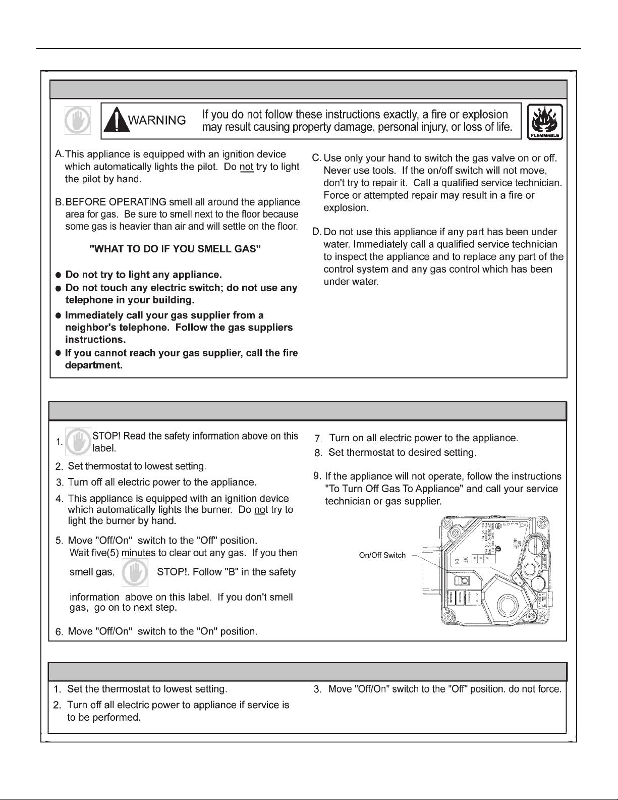
LIGHTING & OPERATION LABEL
FOR YOUR SAFETY READ BEFORE OPERATING
OPERATING INSTRUCTIONS
TO TURN OFF GAS APPLIANCE
29
Page 30
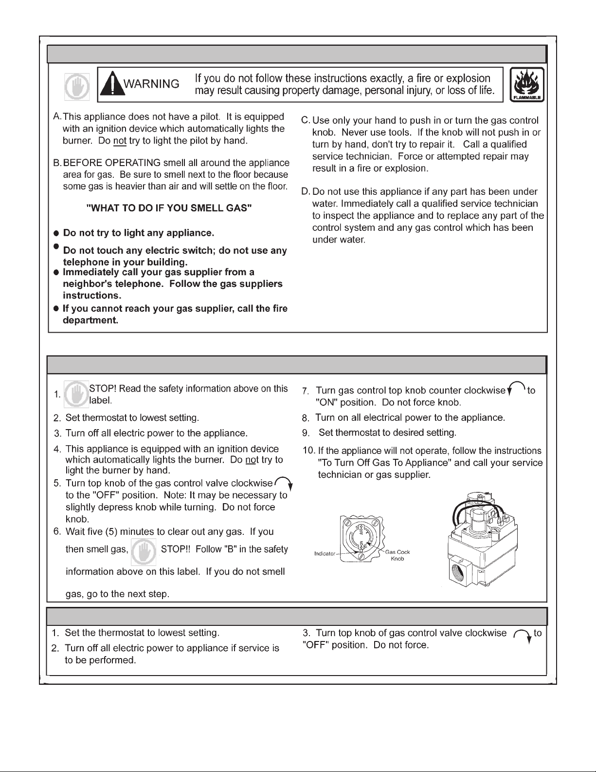
FOR YOUR SAFETY READ BEFORE OPERATING
OPERATING INSTRUCTIONS
TO TURN OFF GAS APPLIANCE
30
Page 31

ADJUSTMENTS
CHECKING THE VENTING
ON INITIAL STARTUP, SOME ADJUSTMENTS MAY BE
NECESSARY.
Check Manifold and inlet gas pressures. See
Gas Supply Systems
(page 13) and (page 31).
Check Pilot Burner. See
Pilot Burner
(page 36).)
TESTING DAMPER OPERATION
With the Service Switch in the AUTOMATIC OPERATION
position, check the operation of the ue damper three (3) times
with the water operating controls for proper operating sequence:
• The damper disc must be open (in the vertical position) before
the ignition and combustion process begins.
• The damper disc must be in the open position when the main
burner is ring.
• The gas control valve must close and the main burner must
have ceased ring before the damper disc begins its return
to the closed (horizontal) position.
If during testing of the operation of the damper you nd that
there is a problem with the operation of the water heater when
the Service Switch is in the AUTOMATIC OPERATION position:
Reset the Service Switch to the HOLD OPEN DAMPER position
and check operation again.
If the water heater does operate when placed in the HOLD OPEN
DAMPER position:
• Refer to the
Guide
(page 40).
Effikal RVGP-KSF-Series Flue Damper Trouble Shooting
• If the water heater does not operate with the Service Switch
in either position:
• Refer to
Checklist
Troubleshooting
(page 41).
(page 39) and
Table 11. Troubleshooting
The following steps shall be followed with each appliance
connected to the venting system placed in operation, while any
other appliances connected to the venting system are not in
operation.
1. Seal any unused openings in the venting system.
2. Inspect the venting system for proper size and horizontal pitch,
as required in the
National Fuel Gas Code, ANSI Z223.1
and these
instructions. Determine that there is no blockage or restriction,
leakage, corrosion and other deciencies which could cause
an unsafe condition.
3. So far as is practical, close all building doors and windows
and all doors between the space in which the water heater(s)
connected to the venting system are located and other spaces
of the building. Turn on all appliances not connected to the
venting system. Turn on all exhaust fans, such as range hoods
and bathroom exhausts, so they shall operate at maximum
speed. Close replace dampers.
4. Follow the lighting instruction. Place the water heater being
inspected in operation. Adjust thermostat so water heater shall
operate continuously.
5. Test for draft hood spillage at the relief opening after 5 minutes
of main burner operation.
6. After it has been determined that each appliance connected
to the venting system properly vents when tested as outlined
above, return doors, windows, exhaust fans, fireplace
dampers and any other gas burning appliance to their previous
conditions of use.
7. If improper venting is observed during any of the above tests,
the venting system must be corrected.
FAILURE TO CORRECT BACK DRAFTS MAY CAUSE AIR
CONTAMINATION AND UNSAFE CONDITIONS.
• If the back draft cannot be corrected by the normal method
or if a suitable draft cannot be obtained, a blower type ue
gas exhauster must be employed to assure proper venting
and correct combustion.
31
Page 32

CHECKING THE INPUT
For installation locations with elevations above 2000 feet, refer
to HIGH ALTITUDE INSTALLATIONS section of this manual for
input reduction procedure.
1. Attach a pressure gauge or a manometer to the manifold
pressure tap on the gas control valve and refer to
Table 8
, for
correct manifold pressure.
2. Use this formula to “clock” the meter. Be sure that other gas
consuming appliances are not operating during this interval.
(3600/T) x H = Btuh
T = Time in seconds to burn one cubic foot of gas.
H = Btu’s per cubic foot of gas.
Btuh = Actual heater input.
Example: (Using 250 heater)
T = 15.1 seconds
H = 1050 Btu
Btuh = ?
(3600/15.1) x 1050 = 250,000 (Compare with 250 model
and rating.)
Table 8. Approximate Time Required To Consume 1 Cu. Ft. Of Gas
Input
Rate
(BTUH)
154,000
at Full Capacity
Type
of
Gas
NATURAL
PROPANE
BTUH
Per
Cu. Ft.
1050
2500
Time Req’d to
Consume 1 Cu. Ft.
Of Gas
24.5 SEC.
58.4 SEC.
Should it be necessary to adjust the gas pressure to the
burners to obtain the full input rate, the steps below should
be followed:
3. Remove the regulator adjustment sealing cap and adjust the
pressure by turning the adjusting screw with a screwdriver.
• Clockwise to increase gas pressure and input rate.
• Counterclockwise to decrease gas pressure and
input rate.
4. “Clock” the meter as in step 2 above.
5. Repeat steps 3 and 4 until the specied input rate is achieved.
6. Turn the gas control knob to PILOT. Remove the pressure
gauge and replace the sealing cap and the Allen wrench set
screw in the pressure tap opening.
UNDER NO CIRCUMSTANCES SHOULD THE GAS INPUT
EXCEED THE INPUT SHOWN ON THE HEATER MODEL AND
RATING PLATE. OVER-FIRING COULD RESULT IN DAMAGE
OR SOOTING OF THE HEATER.
32
Page 33
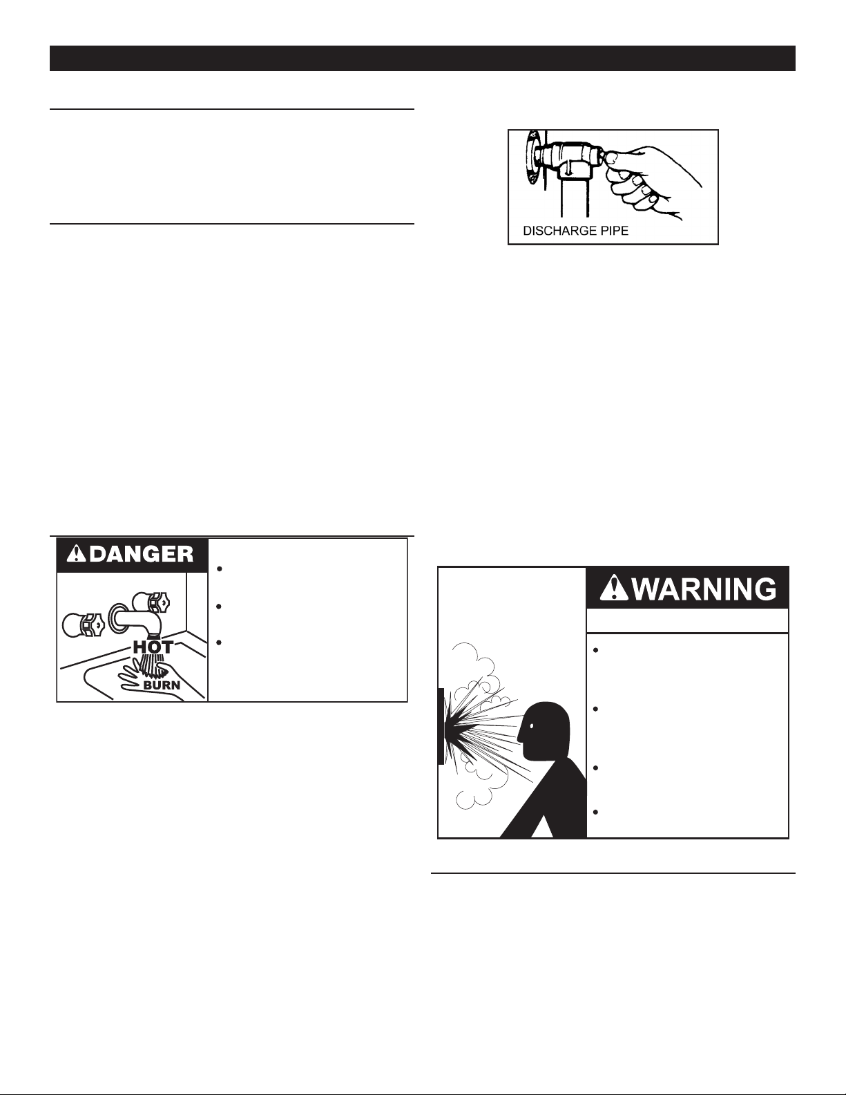
MAINTENANCE
VENTING SYSTEM
Examine the venting system every six months for obstructions
and/or deterioration of the vent piping.
Remove all soot or other obstructions from chimney which will
retard free draft.
REMOTE STORAGE TANK TEMPERATURE CONTROL
The water temperature in the remote storage tank (if used) is
controlled by the storage tank temperature control. The sensing
element is mounted in the hot water storage tank. See
Diagrams
(page 43).
Water Piping
A change in water temperature in the storage tank lower than
the tank temperature control setting will cause the sensor to
activate the circulating pump. The pump then circulates the
water through the heater where the thermostat senses the drop
in water temperature and activates main burner operation of the
water heater.
If the storage tank temperature control is out of calibration,
replace with new control.
SHOULD OVERHEATING OCCUR OR THE GAS SUPPLY FAIL
TO SHUT OFF, TURN OFF THE MANUAL GAS CONTROL
VALVE TO THE Water heater.
TEMPERATURE-PRESSURE RELIEF VALVE TEST
Burn hazard.
Valve with a properly rated/sized new one. See
Pressure Relief Valve
Figure 23. Temperature-Pressure Relief Valve.
(page 15) for instructions on replacement.
Temperature-
If the Temperature-Pressure Relief Valve on water heater weeps
or discharges periodically, this may be due to thermal expansion.
Note: Excessive water pressure is the most common cause of
Temperature-Pressure Relief Valve leakage. Excessive
water system pressure is most often caused by
"thermal expansion" in a "closed system." See
Water Systems
and
Thermal Expansion
(page 14). The
Closed
Temperature-Pressure Relief Valve is not intended for
the constant relief of thermal expansion.
Temperature-Pressure Relief Valve leakage due to pressure build
up in a closed system that does not have a thermal expansion
tank installed is not covered under the limited warranty. Thermal
expansion tanks must be installed on all closed water systems.
DO NOT PLUG THE TEMPERATURE-PRESSURE RELIEF
VALVE OPENING. THIS CAN CAUSE PROPERTY DAMAGE,
SERIOUS INJURY OR DEATH.
Hot water discharge.
Keep clear of TemperaturePressure Relief Valve
discharge outlet.
It is recommended that the Temperature-Pressure Relief Valve
should be checked to ensure that it is in operating condition
every 6 months.
When checking the Temperature-Pressure Relief Valve operation,
make sure that (1) no one is in front of or around the outlet of the
Temperature-Pressure Relief Valve discharge line, and (2) that
the water discharge will not cause any property damage, as the
water may be extremely hot. Use care when operating valve as
the valve may be hot.
To check the pressure relief valve , lift the lever at the end of the
valve several times. See
Figure 23
. The valve should seat properly
and operate freely.
If after manually operating the valve, it fails to completely reset
and continues to release water, immediately close the cold water
inlet to the water heater and drain the water heater. See
and flushing
(page 34). Replace the Temperature-Pressure
Draining
Relief
Explosion Hazard
Temperature-Pressure Relief Valve
must comply with ANSI Z21.22CSA 4.4 and ASME code.
Properly sized temperaturepressure relief valve must be
installed in opening provided.
Can result in overheating and
excessive tank pressure.
Can cause serious injury or death.
ANODE ROD INSPECTION
The anode rod is used to protect the tank from corrosion. Most
hot water tanks are equipped with an anode rod. The submerged
rod sacrices itself to protect the tank. Instead of corroding tank,
water ions attack and eat away the anode rod. This does not
affect water’s taste or color. The rod must be maintained to keep
tank in operating condition.
33
Page 34
Property Damage Hazard
CAUTION
Burn harzard.
Hot water discharge.
Keep hands clear of drain
valve discharge.
Avoid water heater damage.
•
Inspection and replacement of anode rod required.
•
Anode rod deterioration depends on water conductivity, not
necessarily water condition. A corroded or pitted anode rod
indicates high water conductivity and should be checked and/
or replaced more often than an anode rod that appears to be
intact. Replacement of a depleted anode rod can extend the life of
your water heater. Inspection should be conducted by a qualied
technician, and at a minimum should be checked annually after
the warranty period.
Articially softened water is exceedingly corrosive because the
process substitutes sodium ions for magnesium and calcium ions.
The use of a water softener may decrease the life of the water
heater tank.
The anode rod should be inspected after a maximum of three
years and annually thereafter until the condition of the anode rod
dictates its replacement. Anode replacement is not covered by
warranty. NOTE: articially softened water requires the anode
rod to be inspected annually.
DRAINING AND FLUSHING
8. Close the water heater drain valve when all water in the
storage tank has drained.
9. Close the hot water faucet opened in Step 4.
10. If the water heater is going to be shut down for an extended
period, the drain valve should be left open.
TO FLUSH THE WATER HEATER STORAGE TANK:
1. Turn off the electrical supply to the water heater.
2. Ensure the cold water inlet valve is open.
3. Open a nearby hot water faucet and let the water run until
the water is no longer hot. Then close the hot water faucet.
4. Connect a hose to the drain valve and terminate it to an
adequate drain.
5. Ensure the drain hose is secured before and during the entire
ushing procedure. Flushing is performed with system water
pressure applied to the water heater.
6. Open the water heater drain valve to ush the storage tank.
7. Flush the water heater storage tank to remove sediment and
allow the water to ow until it runs clean.
8. Close the water heater drain valve when ushing is completed.
9. Remove the drain hose.
10. Fill the water heater - see
11. Turn on the electrical supply to place the water heater back
in operation.
12. Allow the water heater to complete several heating cycles to
ensure it is operating properly.
REMOVING LIME DEPOSITS FROM TANK TYPE COMMERCIAL WATER HEATERS
Filling the Water Heater
(page 27).
It is recommended that the water heater storage tank be drained
and ushed every 6 months to reduce sediment buildup. The
water heater should be drained if being shut down during
freezing temperatures. See
in this manual for the location of the water heater components
described below.
TO DRAIN THE WATER HEATER STORAGE TANK:
1. Turn off the electrical supply to the water heater.
2. Turn off the gas supply at the Main Gas Shutoff Valve if the
water heater is going to be shut down for an extended period.
3. Ensure the cold water inlet valve is open.
4. Open a nearby hot water faucet and let the water run until the
water is no longer hot.
5. Close the cold water inlet valve to the water heater.
6. Connect a hose to the water heater drain valve and terminate
it to an adequate drain.
7. Open the water heater drain valve and allow all the water to
drain from the storage tank.
Features and Components
(page 7)
The amount of calcium carbonate (lime) released from water is
in direct proportion to water temperature and usage. See
24
. The higher the water temperature or water usage, the more
lime deposits are dropped out of the water. This is the lime scale
which forms in pipes, heaters and on cooking utensils.
Lime accumulation not only reduces the life of equipment but also
reduces efciency of the heater and increases fuel consumption.
The usage of water softening equipment greatly reduces the
hardness of the water. However, this equipment does not
always remove all of the hardness (lime). For this reason it is
recommended that a regular schedule for deliming be maintained.
The time between cleaning will vary from weeks to months
depending upon water conditions and usage.
The depth of lime buildup should be measured periodically.
Heaters equipped with cleanouts will have about 2" of lime buildup
when the level of lime has reached the bottom of the cleanout
opening. A schedule for deliming should then be set up,based
on the amount of time it would take for a 1" buildup of lime. It is
recommended that the water heater initially be inspected after
6 months.
EXAMPLE 1:
Initial inspection after 6 months shows 1/2" of lime accumulation.
Therefore, the heater should be delimed once a year.
34
Figure
Page 35
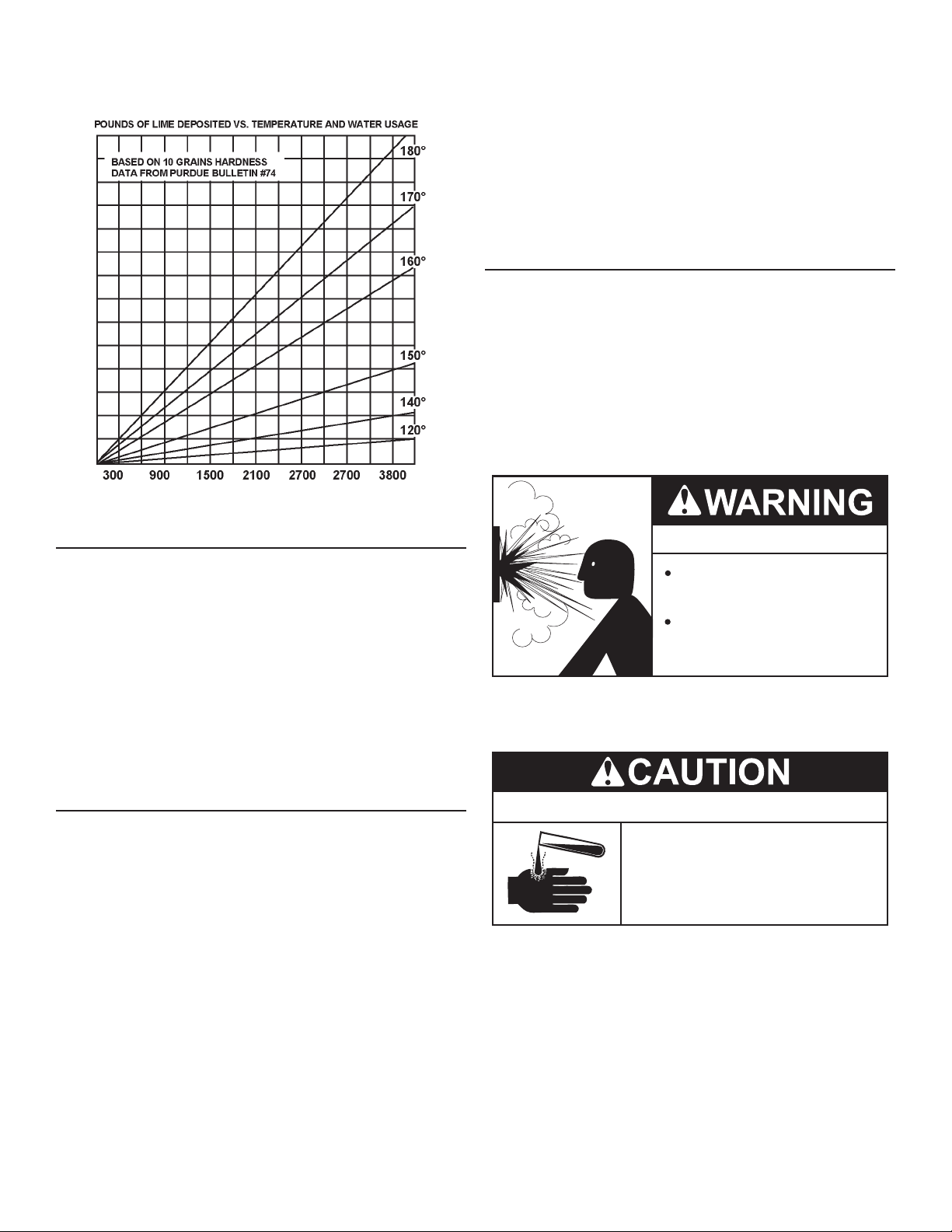
EXAMPLE 2:
Initial inspection after 6 months shows 2" of lime accumulation.
Therefore, the heater should be delimed every 3 months.
Figure 24. Lime Accumulation after Six Months
5. Inspect cleanout plate gasket, if new gasket is required,
replace with part no. 100109686.
6. Install cleanout plate. Be sure to draw plate up tight by
tightening screws securely.
7. Replace outer jacket cover plate.
In some water areas the sediment might not be removed by this
method and may result in the water heater making rumbling or
boiling noises. To dissolve and remove these more stubborn
mineral deposits, UN•LIME Professional Delimer should be used.
DELIMING USING FLO-JUG METHOD
UN•LIME in the 5 gallon size is recommended for deliming of all
models. Contact your local dealer, distributor or, water heater
manufacturer:
Telephone: (800) 433-2545
Fax: (800) 433-2515
Website: www.hotwater.com/parts
PREPARE THE WATER HEATER
To delime the water heater using the Flo-Jug method, rst prepare
the heater for deliming.
DELIMING SOLVENTS
UN•LIME is recommended for deliming. UN•LIME is a patented
food grade acid which is safe to handle and does not create the
harmful fumes which are associated with other products.
UN•LIME may be obtained from your dealer, distributor or water
heater manufacturer. Order Part Number 100110459,1 gallon,
packed 4 gallons per case or Part Number 100110460, 5 gallon
container.
Hydrochloric base acids are not recommended for use on glass
lined tanks.
Observe handling instructions on label of product being used.
TANK CLEANOUT PROCEDURE
The following practices will ensure longer life and enable the unit
to operate at its designed efciency:
1. Once a month the heater should be ushed. Open the drain
valve and allow two gallons of water to drain from the heater.
Inlet water valve should remain open to maintain pressure
in tank.
2. A cleanout opening is provided for periodic cleaning of the
tank. Gas must be shut off and heater drained before opening
cleanout.
Explosion Hazard
Flammable hydrogen gases
may be present.
Keep all ignition sources away
from faucet when turning on
hot water.
Do not smoke or have open ame or sparks in vicinity of heater.
Do not mix UN•LIME with other chemicals. Do not allow contact
with magnesium, aluminum or galvanized metals.
Chemical Hazard
• Product contains phosphoric acid.
• Keep out of reach of children.
• Use rubber or neoprene gloves.
Contains phosphoric acid. In case of external contact, ush with
cool water. If irritation persists, get medical attention. If swallowed,
give 1 or 2 glasses of water or milk and call physician.
To clean heater through cleanout opening, proceed as follows:
1. Drain heater.
2. Remove outer cover plate from lower side of heater jacket.
3. Remove six (6) hex head screws securing tank cleanout plate
and remove plate.
4. Remove lime, scale, or sediment using care not to damage
the glass lining.
Get immediate medical attention for eyes. Keep out of reach of
children.
Note: THE USE OF RUBBER OR NEOPRENE GLOVES IS
RECOMMENDED, ESPECIALLY IF YOU HAVE ANY
OPEN SORES OR CUTS TO AVOID UNNECESSARY
IRRITATION OR DISCOMFORT.
35
Page 36
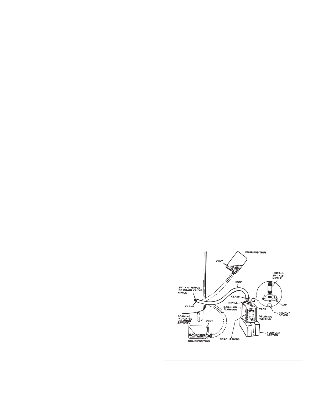
DELIME THE WATER HEATER
1. Turn off fuel and/or power supply to heater. Also, turn off power
to any electrical device or equipment, which is attached, or
part of the system.
2. Open hot water side of faucet closest to heater and allow water
to run until it is cool enough to handle safely.
3. Close cold water inlet valve to heater.
4. Connect hose to drain valve at bottom of heater and start
draining heater into suitable oor drain area.
5. Remove pressure relief valve while heater is draining.
NOTE: Do not replace pressure relief valve until deliming is
completed. Pressure relief valve opening will also act as a vent
in case of possible contact between the delimer and the anode
rod(s), which may produce ammable hydrogen-air mixtures.
6. If pressure relief valve appears to be limed-up, place it in a
clean glass or plastic container adequate in size so that you
can pour enough UN•LIME® into container to cover the valve
and allow space for foaming. When foaming stops, run fresh
cool water into the container and rinse the pressure relief
valve for a few minutes.
7. If heater does not drain completely after a reasonable length
of time, turn off the main water supply valve to stop water from
entering the tank due to a by-pass problem or defective cold
water inlet valve. Also, check for clogged drain valve opening.
Heater must be completely drained before introducing
UN•LIME.
8. Remove the cleanout cover and place a clean plastic bucket
next to the cleanout opening.
Partially open the cold water inlet valve to allow time to
accomplish the following and then close the valve.
While the water is being run through the tank, insert a stiff
wire, copper tube attened at one end or an opened wire
coat hanger through the cleanout opening and scrape out any
loose deposits of scale or sediment. This is an economical
way to avoid unnecessary usage of the deliming solution.
Note: If your container does not have the vent cap and
vent boss, drill a 3/16” hole in the handle. When
you have nished deliming you will be able to plug
this drilled vent with the stainless steel screw that is
supplied with the kit.
2. Remove the container’s cap and cut the plastic membrane
located in the 3/4” IPT opening in the cap. Take care to not
damage the threads.
3. Find the 3/4” male adapter, apply teon tape to the threaded
end and screw it into the 3/4” IPT opening in the cap.
4. Put cap with male adapter back on the container and slide
3/4” hose over end of male adapter and fasten in place using
hose clamp provided.
DELIME USING FLO-JUG METHOD
1. Slide the hose clamp over end of hose and slide hose over the
male adapter in the water heater drain opening and secure in
place using hose clamp.
2. Lift container to the “Pour” Position (see
Figure 25)
, being
careful to keep the vent in the handle above the liquid level
and pour the UN•LIME into the heater.
3. Lower container, you may have to place the container on its
empty carton to prevent the UN•LIME from owing back into
the container.
4. Let UN•LIME remain in the heater for 5 minutes and then lower
the container to the “Drain” Position. See
Figure 25
.
5. Deliming activity is indicated by foaming on the surface of the
UN•LIME. If there is deliming activity, repeat steps 2 thru 4.
Normally, lime removal will be completed within one hour. Severe
build-up of lime may take longer than an hour to complete
descaling.
Note: To check UN•LIME for continued use, place some
scale or white chalk in a glass with a small amount of
UN•LIME. If the material is vigorously dissolved by the
UN•LIME, it can be reused; if not, the UN•LIME should
be replaced.
Repeat the opening and closing of the cold water inlet valve
as necessary but be sure the heater is completely drained
when ready to introduce the UN•LIME.
Upon completion, reinstall the cleanout cover and use a new
cleanout cover gasket (part number 100109686).
Remove the drain valve.
9. Install the long plastic male adapter insert tting into the drain
valve opening of heater after applying Teon tape or paste to
threads. Tighten rmly by hand and use wrench or adjustable
pliers to check for secure connection. Do not over tighten to
avoid damage to threads and ttings.
PREPARE THE UP-N-DOWN TRANSFER KIT
The next step is the preparation on the Up-N-Down Transfer Kit,
if you have not already done so:
1. With the 5 gallon Up-N-Down container in the vertical position,
unscrew the plastic vent cap in the handle and pierce the
plastic membrane over the vent boss under the cap to allow
the container to vent.
Figure 25. Flo-Jug Deliming Method
PILOT BURNER
At least once a year, check the pilot burner (
main burner,
Figure 28
, for proper operation. See
Figure 26)
Figure 27
and the
for the
location of the Pilot Burner and the Main Burners. For access to
pilot, unfasten two screws to burner cover and remove. Locate
36
Page 37
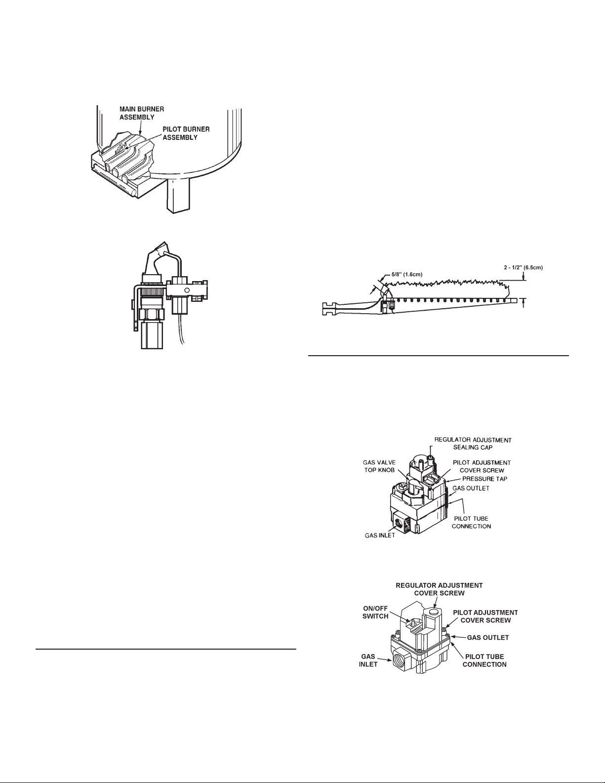
the burner with pilot and remove screw holding burner to manifold.
Unfasten pilot tubing from valve and slide out burner and pilot.
Servicing of the pilot burner includes keeping pilot free of lint,
cleaning the burner head, the primary air opening and the orice
of the pilot burner.
Figure 26. Checking the Pilot Burner
• Give reasonably quiet operation during ignition, burning and
extinction.
• Cause no excessive lifting of ame from burner ports.
If the preceding burner characteristics are not evident, check
for accumulation of lint or other foreign material that restricts
or other foreign material that restricts or blocks air openings to
burner or heater.
To clean main burners:
1. Remove main burners from unit.
2. Check that burner venturi and ports are free of foreign matter.
3. Clean burners with bristle brush and/or vacuum cleaner
• DO NOT distort burner ports or pilot location.
4. Reinstall burners in unit. Make sure front and rear of
burners are installed correctly in burner support brackets.
Also check for good ow of combustion and ventilating air to
the unit.
Figure 27. Locating the Pilot and Main Burners
The pilot burner ame is affected by the following:
1. Low gas pressure.
• Adjust pilot ame by means of the pilot gas adjustment
located on the gas control valve. See
Figure 29
and
Figure 30
• The pilot ame should envelop sensing device with 5/8”
(1.6cm) ame. See
cover screw shown in
Figure 28
Figure 29
. Remove pilot adjustment
and
Figure 30
. Turn
inner adjustment screw clockwise to decrease, or
counterclockwise to increase pilot flame. Be sure to
replace cover screw on gas control valve after adjustment
to prevent possible gas leakage.
2. Clogged pilot burner orice.
• Clean or replace orice. A clogged orice will restrict gas
ow.
Pilot sensing device must sense a ame before sparking will stop.
Loose wires or a draft may cause intermittent or abnormal
sparking. To eliminate this condition, rst correct loose wiring
condition, and then, if necessary, increase pilot ame.
Figure 28. Typical Pilot and Main Burner Flames
GAS CONTROL VALVE
Figure 29
and
Figure 30
show the two types of combination gas
control valves used on this heater.
If gas control valve becomes defective, repairs should not be
attempted. A new valve should be installed in place of defective
one.
.
Figure 29. LP Gas Valve
MAIN BURNER
The main burner shown in
Figure 28
, should display the following
characteristics:
• Cause rapid ignition and carry over of ame across entire
burner.
Figure 30. Natural Gas Valve
37
Page 38

SERVICE
The installer may be able to observe and correct certain problems which may arise when the unit is put into operation. HOWEVER,
it is recommended that only a qualied service technician or qualied agencies, using appropriate test equipment, be allowed to
service the heater.
As preliminary step, check wiring against diagram, check for grounded, broken or loose wires. Check all wire ends to be sure
that they are making good contact.
ELECTRICAL SERVICING
LABEL ALL WIRES PRIOR TO DISCONNECTION WHEN SERVICING CONTROLS. WIRING ERRORS CAN CAUSE IMPROPER
AND DANGEROUS OPERATION.
VERIFY PROPER OPERATION AFTER SERVICING.
38
Page 39
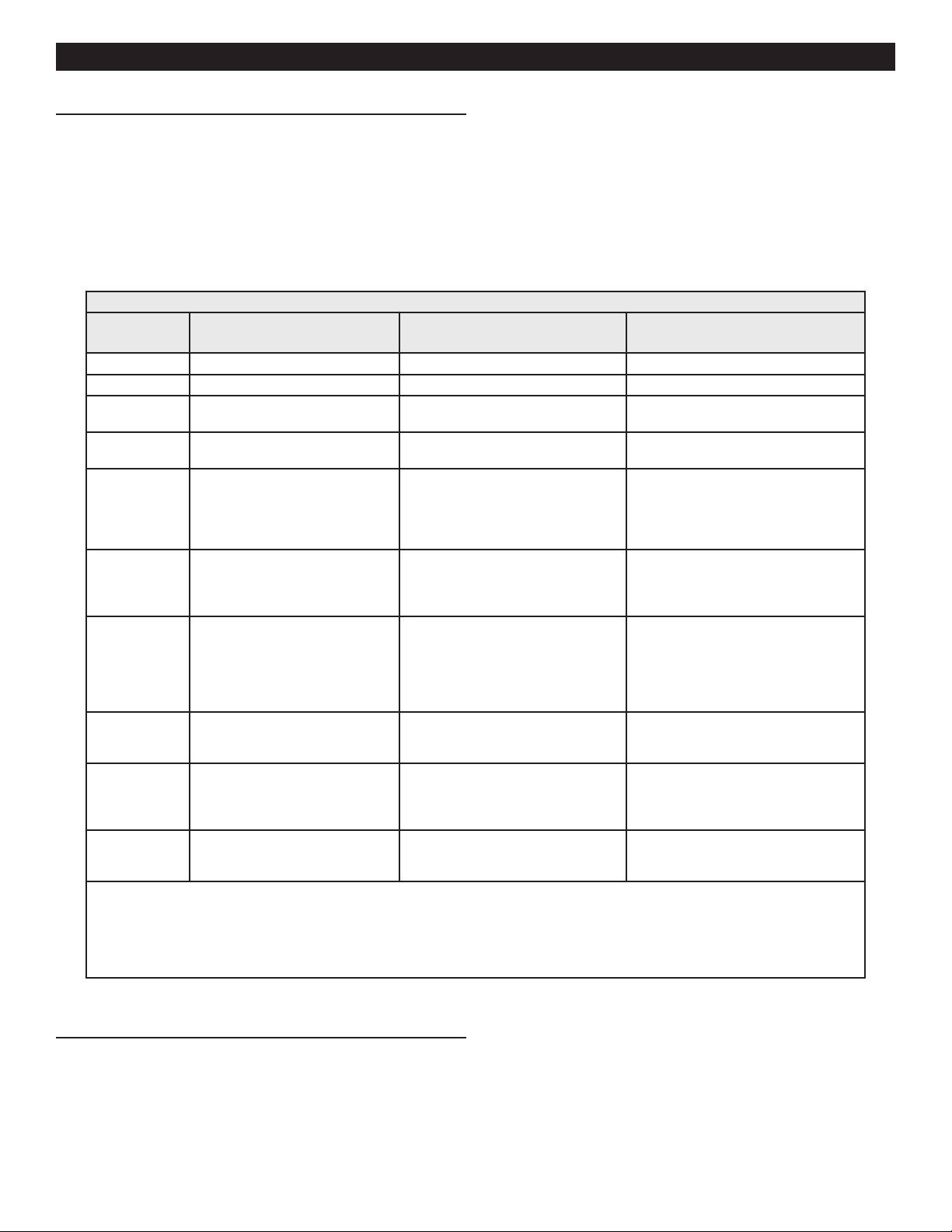
TROUBLESHOOTING
IGNITION MODULE
Before calling your service agent, the following checklist should
be examined to eliminate obvious problems from those requiring
replacement or servicing.
• Check that “main manual gas shut-off valve” is fully open and
that gas service has not been interrupted.
• Check that after following the water
Operating Instructions
, the
• Is the water temperature in tank below the thermostat dial
setting on the thermostat (calling for heat)?
• It is possible that the high limit (E.C.O.) has functioned to shut
off the water heater. See FEATURES - Water Temperature
Control in the
Operating Instructions
for reset procedure. Contact
your serviceman if limit continues to function to shut off water
heater.
“Top Knob” of the gas control valve is in “ON” position.
• Check electrical supply to the water heater for possible blown
(or tripped) fusing or power interruption.
Table 9. Troubleshooting Flash Codes
Green LED
Flash Code
OFF No "Call for Heat Not applicable None
Flash Fast Power up - internal check Not applicable None
Heartbeat Normal startup - ignition sequence
4 Secons ON
the "x" ashes
A Flash Code Descriptions:
- Flash Fast: rapid blinking.
- Heartbeat: constant 1/2 second bright, 1/2 second dim cycles.
- 4 second solid on pulse followed by "x" 1 second flashes indicates flame current to the nearest μA
- A single flash code number signifies that the LED flashes X times at 2 Hz, remains off for two seconds, and them repeats the sequence.
a
started (including prepurge
Device in run mode. "x" = Flame
current to the nearest μA.
2 5 minute Retry Delay - Pilot ame
not detected during trial for ignition
3 Recycle - Flame failed during run Initiate new trial for ignition. Flash
4 Flame sensed out of sequence If situation self-corrects within 10
6 Control Internal Error Control remains in wait mode. When
7 Flame rod shorted to ground Control remains in wait mode. When
8 Low secondary voltage supply Control remains in wait mode. When
Indicates Next System Action Recommended Service Action
Not applicable None
Not applicable None
Initiate new trial for ignition after retry
delay completed.
code will remain through the ignition
trial until ame is proved.
seconds, control returns to normal
sequence. If ame out of sequence remains longer than 10 seconds, control
will resume normal operation 1 hour
after error is corrected.
the fault corrects, control resumes
normal operation.
the fault corrects, control resumes
normal operation.
the fault corrects, control resumes
normal operation.
If system fails to light on next trial for
ignition, check gas supply, pilot burner,
spark- and ame-sense wiring, ame-rod
contaminated or out of position, burner
ground connection.
If system fails to light on next trial for
ignition, check gas supply, pilot burner,
ame-sense wiring, contamination of
ame rod, burner ground connection.
Check for pilot ame. Replace gas valve
if pilot ame present. If no pilot ame,
cycle "Call for Heat." If error repeats,
replace control.
Cycle "Call for Heat." If error repeats,
replace control.
Check ame-sense lead wire for damage
or shorting. Check that ame rod is in
proper position Check ame rod ceramic
for cracks, damage or tracking.
Check transformer and AC line for proper input voltage to the control. Check
with full system load on the transformer.
FLUE DAMPER
Do not turn damper open manually or motor damage will result,
use the service switch. All readings are taken from harness
receptacle. Do not push meter leads into harness receptacle.
This opens the pins and will create connection problems. See
the following
Guide
(page 40).
39
Effikal RVGP-KSF-Series Flue Damper Trouble Shooting
Page 40
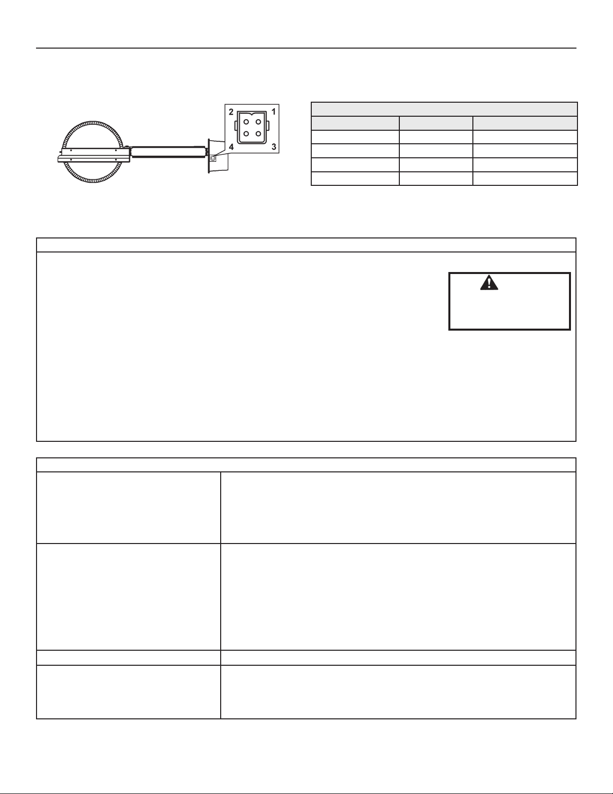
EFFIKAL RVGP-KSF-SERIES FLUE DAMPER TROUBLE SHOOTING GUIDE
Do not turn damper open manually or motor damage will result,
use the service switch. All readings are taken from harness
Figure 31. Damper Disc Shown in Open Position
24 V.A.C. NORMAL SEQUENCE OF OPERATION
receptacle. Do not push meter leads into harness receptacle.
This opens the pins and will create connection problems.
Table 10. Efkal Damper Pinouts & Wire Colors
Efkal Wires Function Adapter Wire Colors In*
1. Brown 24 VAC HOT Black
2. Orange Signal In Yellow
3. Yellow Signal Out Red
4. Black 24 VAC Common White
A. FLUE DAMPER OPEN OR OPENING (Unit is calling for heat and damper disc should be in vertical position)
VOLTAGE ACROSS:
4 & 1 All Times that High Limit is closed
4 & 2 Calling for Heat Open or Opening
Do not negate the action
WARNING
of any existing safety
or operational controls.
4 & 3 During Combustion Damper Open+
B. FLUE DAMPER CLOSED (Unit is not calling for heat and damper disc should be in horizontal position)
NOTE: POSITION 4 IS COMMON AND POSITION 3 IS HOT 24 VAC VOLTAGE ACROSS:
4 & 1 All Times that High Limit is closed
NO VOLTAGE ACROSS:
4 & 3 or 4 & 2 1. Thermostat not calling for heat.
ABNORMAL OPERATION
A. NOTHING WORKING; NO VOLTAGE
ACROSS: 4 & 1; 4 & 2; 4 & 3:
1. High Limit has tripped and is OPEN. Determine reason for tripping of high limit
2. Bad Transformer
3. Loose or broken connections
4. Blown fuse or circuit breaker
5. Disconnect switch off
6. Harness not plugged into water heater receptacle
B. DAMPER HAS OPENED, NO
COMBUSTION VOLTAGE ACROSS
1. Check for power at ignition module terminals. If 24VAC power is present damper
is working properly.
2. Defective component in water heater after the ue damper.
3. If 24 VAC is not present at the ignition module, look for loose or broken
connections between damper and ignition module.
4. If the connections from damper to ignition module seem proper, replace damper
assembly. If a damper assembly is not available, place the service switch in the
hold open position. This should keep the damper in the open position and allow
the customer to have automatic heat, until a replacement damper can be installed.
C. DAMPER ROTATES CONTINUOUSLY
D. DAMPER STICKS
1. Change the entire damper assembly
1. Make sure no screws obstruct the damper blade.
2. Make sure damper pipe assembly is not egg shaped.
3. Make sure damper rod is not rubbing on pipe assembly.
See gure on front page of this insert sheet
Important: DAMPER MUST BE OPEN BEFORE
A.O. Smith Technical Center at 1-800-527-1953.
COMBUSTION TAKES PLACE. If all steps have
been tried and damper problems persists call
40
Page 41
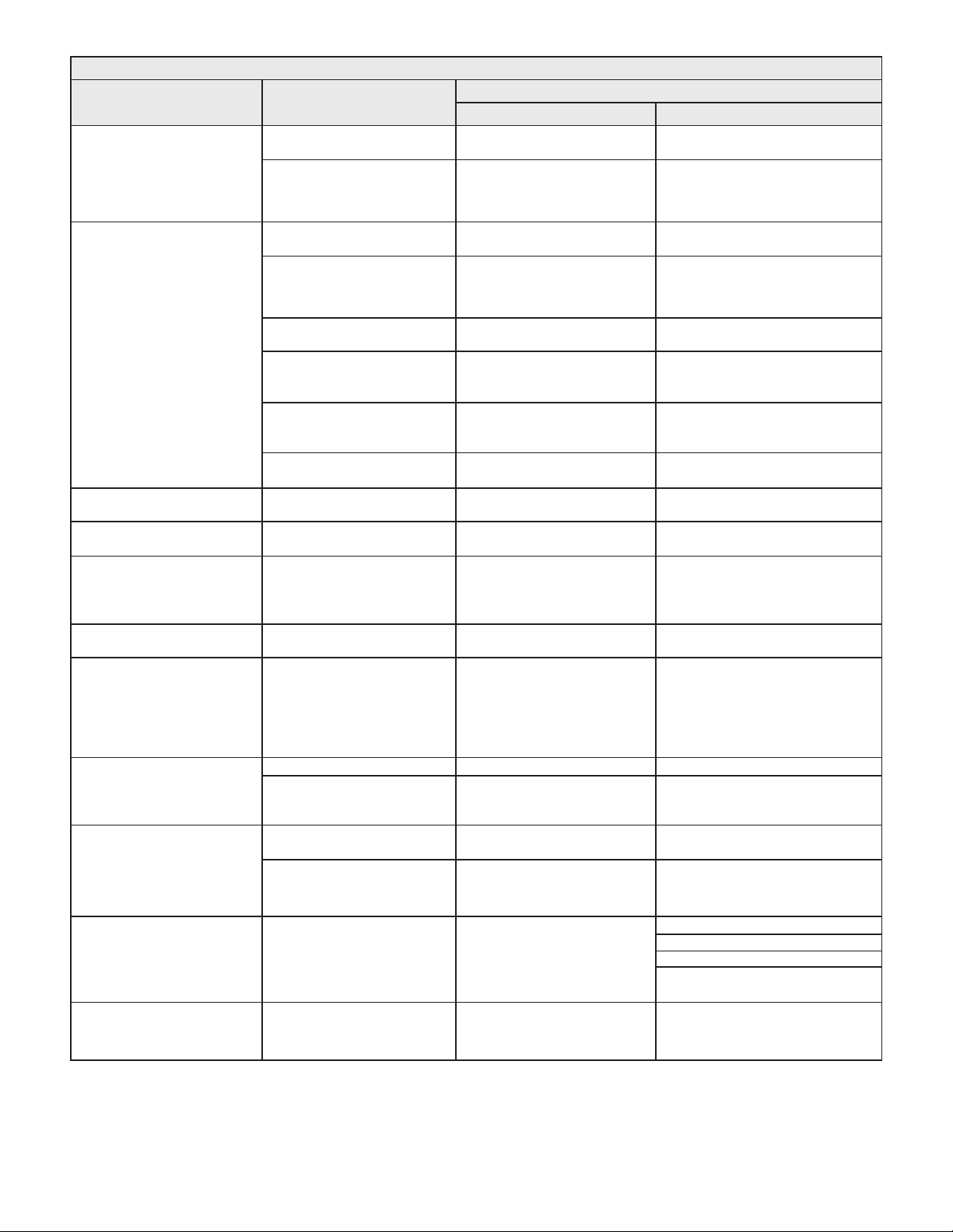
COMPLAINT CAUSE
Water not hot enough.
Insufcient hot water
Table 11. Troubleshooting Checklist
Thermostat set too low.
Upper and/or lower temperature
probe out of calibration.
Thermostat set too low.
Upper and/or lower temperature
probe out of calibration.
Main manual gas shutoff valve
partially closed.
Heater too small for demand.
REMEDY
USER QUALIFIED SERVICE AGENCY
Set thermostat dial to a higher
temperature.
Call qualied service agency.
Set thermostat dial to a higher
temperature.
Call qualied service agency.
Open main manual gas shutoff
valve to fullest extent.
Space usage to give heater time to
restore water temperature.
Check continuity and resistance
(Ohms) of upper and lower thermostat probes. Replace probes if out of
specication.
Check continuity and resistance
(Ohms) of upper and lower thermostat probes. Replace probes if out of
specication..
Heater recovery is slower. Call qualied service agency.
Draft hood not installed or one or
more bafes.
Water temperature too hot. Thermostat set too high. Set thermostat to a lower setting.
Heater makes sounds: sizzling.
Rumbling.
Ticking or metallic sounds.
Pounding / water hammer.
Combustion noises.
Water leaks.
Gas odors.
Condensation on outside of tank
- normal.
Sediment accumulation on bottom of tank.
Expansion and contractionnormal.
Air chambers in piping have
become waterlogged. Thermal expansion tank damaged,
improperly charged, or improperly
sized.
Too much primary air. Adjust shutters.
Overtired heater. Incorrect burners or orice for types of gas
used.
Drain valve not closed tightly.
If leakage source cannot be corrected or identied, call qualied
service agency.
Heater is overtired.
Call qualied service agency.
Drain a quantity of water through
drain valve. If rumbling persists,
call a qualied service agency.
Drain piping system and rell.
Heater must be off while this is
being done. Check thermal expansion tank charge pressure when
the water system pressure is zero.
Call qualied service agency. Check and correct as necessary.
If drain valve cannot be closed
tightly, replace.
Shut off gas supply to heater and
close cold water inlet valve to
heater.
Shut off gas supply to heater and
call qualied service agency.
Check gas input. If incorrect, adjust gas
pressure or replace main burner orice.
Install draft hood or bafes as furnished
with unit.
Delime heater.
Follow the manufacturer's
instructions for proper charging
of the thermal expansion tank.
Repair or in case of suspected tank
leakage, be certain to conrm before
replacing heater.
Check for sooted ue passage.
Check for obstructed vent line.
Check backdraft or lack of draft.
Draft hood may be improperly installed
or not sized properly.
Possible gas leaks.
Shut off gas supply to heater and
call gas company at once.
41
Page 42

FOR YOUR INFORMATION
START UP CONDITIONS
SMOKE/ODOR
It is not uncommon to experience a small amount of smoke and
odor during the initial start-up. This is due to burning off of oil
from metal parts, and will disappear in a short while.
STRANGE SOUNDS
Possible noises due to expansion and contraction of some metal
parts during periods of heat-up and cool-down do not necessarily
represent harmful or dangerous conditions.
Condensation causes sizzling and popping within the burner area
during heating and cooling periods and should be considered
normal. See
CONDENSATION
Whenever the water heater is filled with cold water, some
condensate will form while the burner is on. A water heater may
appear to be leaking when in fact the water is condensation.
This usually happens when:
• A new water heater is lled with cold water for the rst time.
• Burning gas produces water vapor in water heaters,
particularly high efciency models where ue temperatures
are lower.
• Large amounts of hot water are used in a short time and the
rell water in the tank is very cold.
Moisture from the products of combustion condense on the
cooler tank surfaces and form drops of water which may fall
onto the burner or other hot surfaces to produce a “sizzling” or
“frying” noise.
OPERATIONAL CONDITIONS
HOT WATER ODOR
In each water heater there is installed at least one anode rod
for corrosion protection of the tank. Certain water conditions
will cause a reaction between this rod and the water. The most
common complaint associated with the anode rod is one of a
“rotten egg smell” in the hot water. The smell is a result of four
factors which must all be present for the odor to develop:
• A concentration of sulfate in the supply water.
• Little or no dissolved oxygen in the water.
Condensation
next in this manual.
• A sulfate reducing bacteria which has accumulated within the
water heater (this harmless bacteria is nontoxic to humans).
• An excess of active hydrogen in the tank. This is caused by
the corrosion protective action of the anode rod.
Smelly water may be eliminated or reduced in some water
heater models by replacing the anode rod(s) with one of less
active material, and then chlorinating water heater tank and all
water lines.
Contact the local water heater supplier or service agency for
further information concerning an Anode Rod Replacement Kit
and this chlorination treatment.
If smelly water persists after anode rod replacement and
chlorination treatment, we can only suggest that chlorination
or aeration of the water supply be considered to eliminate the
water problem.
Do not remove the anode rod leaving the tank unprotected. By
doing so, all warranty on the water heater tank is voided.
AIR IN HOT WATER FAUCETS
HYDROGEN GAS: Hydrogen gas can be produced in a hot
water system that has not been used for a long period of time
(generally two weeks or more). Hydrogen gas is extremely
ammable and explosive. To prevent the possibility of injury under
these conditions, we recommend the hot water faucet, located
farthest away, be opened for several minutes before any electrical
appliances which are connected to the hot water system are used
(such as a dishwasher or washing machine). If hydrogen gas is
present, there will probably be an unusual sound similar to air
escaping through the pipe as the hot water faucet is opened.
There must be no smoking or open ame near the faucet at the
time it is open.
HIGH WATER TEMPERATURE SHUT OFF SYSTEM
This water heater is equipped with a manual reset type high limit
(Energy Cutout) switch. The high limit switch interrupts the main
burner gas ow should water temperature reach 203°F (95°C).
In the event of high limit switch operation, the water heater
cannot be restarted unless the water temperature is reduced
to approximately 120F (49C). The high limit reset button on the
front of the thermostat then needs to be depressed. See
for the location of the reset button.
Figure 2
42
Page 43
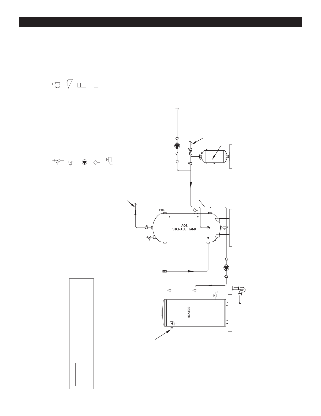
WATER PIPING DIAGRAMS
E
FINISHED
FLOOR
HOT WATER
TO FIXTURES
COLD WATER
SUPPLY
EXPANSION
TANK
ALT. COLD WATER
CONNECTION
HOT WATER RETURN
FROM FIXTURES
PIPE T&P TO
OPEN DRAIN
FULL PORT BALL VALV
CHECK VALVE
TEMPERATURE GAGE
WATER FLOW SWITCH
LEGEND
TEMPERATURE & PRESSURE
RELIEF VALVE
PRESSURE RELIEF VALVE
CIRCULATING PUMP
TANK TEMPERATURE CONTROL
DRAIN
MULTI FLUE - (1 UNIT) WITH VERTICAL STORAGE TANK
WARNING: THIS DRAWING SHOWS SUGGESTED
PIPING CONFIGURATION AND OTHER DEVICES;
CHECK WITH LOCAL CODES AND ORDINANCES
FOR ADDITIONAL REQUIREMENTS.
NOTES:
1. Preferred piping diagram.
2. The temperature and pressure relief valve setting shall not exceed pressure rating of any component in the system.
3. Service valves are shown for servicing unit. However, local codes shall govern their usage.
4. The Tank Temperature Control should be wired to and control the pump between the water heater(s) and the storage tank(s).
5. The water heater’s operating thermostat should be set 5 degrees F higher than the Tank Temperature Control.
43
Page 44
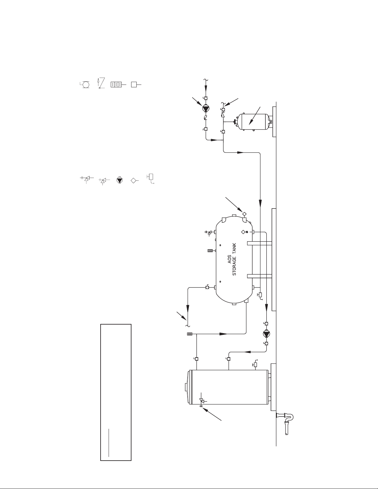
NOTES:
1. Preferred piping diagram.
2. The temperature and pressure relief valve setting shall not exceed pressure rating of any component in the system.
3. Service valves are shown for servicing unit. However, local codes shall govern their usage.
4. The Tank Temperature Control should be wired to and control the pump between the water heater(s) and the storage tank(s).
5. The water heater’s operating thermostat should be set 5 degrees F higher than the Tank Temperature Control.
FULL PORT BALL VALV
E
FINISHED
FLOOR
HOT WATER TO FIXTURES
COLD WATER
SUPPLY
HOT WATER
RETURN FROM
FIXTURES
ALTERNATE
LOCATION
CIRCULATING PUMP
EXPANSION
TANK
PIPE T&P TO
OPEN DRAIN
CHECK VALVE
TEMPERATURE GAGE
WATER FLOW SWITCH
LEGEND
TEMPERATURE & PRESSURE
RELIEF VALVE
PRESSURE RELIEF VALVE
CIRCULATING PUMP
TANK TEMPERATURE CONTROL
DRAIN
WARNING: THIS DRAWING SHOWS SUGGESTED
PIPING CONFIGURATION AND OTHER DEVICES;
CHECK WITH LOCAL CODES AND ORDINANCES
MULTI FLUE - (1 UNIT) WITH HORIZONTAL STORAGE TANK
FOR ADDITIONAL REQUIREMENTS.
44
Page 45
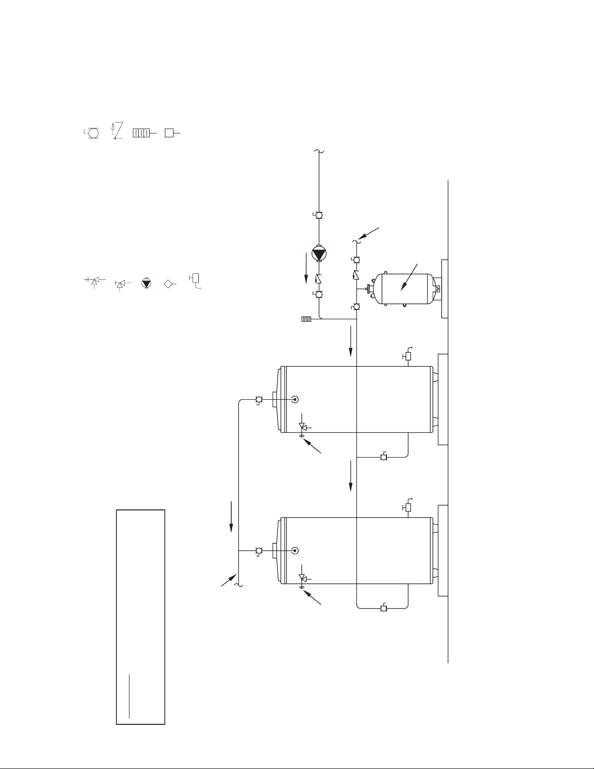
FULL PORT BALL VALV
E
HOT WATER
TO FIXTURES
COLD WATER
SUPPLY
HOT WATER
RETURN
EXPANSION
TANK
PIPE T&P TO
OPEN DRAIN
PIPE T&P TO
OPEN DRAIN
CHECK VALVE
LEGEND
TEMPERATURE & PRESSURE
RELIEF VALVE
PRESSURE RELIEF VALVE
TEMPERATURE GAGE
CIRCULATING PUMP
WATER FLOW SWITCH
DRAIN
TANK TEMPERATURE CONTROL
MULTI FLUE - (2 UNITS)
WARNING: THIS DRAWING SHOWS SUGGESTED
PIPING CONFIGURATION AND OTHER DEVICES;
CHECK WITH LOCAL CODES AND ORDINANCES
FOR ADDITIONAL REQUIREMENTS.
NOTES:
1. Preferred piping diagram.
2. The temperature and pressure relief valve setting shall not exceed pressure rating of any component in the system.
3. Service valves are shown for servicing unit. However, local codes shall govern their usage.
4. The Tank Temperature Control should be wired to and control the pump between the water heater(s) and the storage tank(s).
45
Page 46
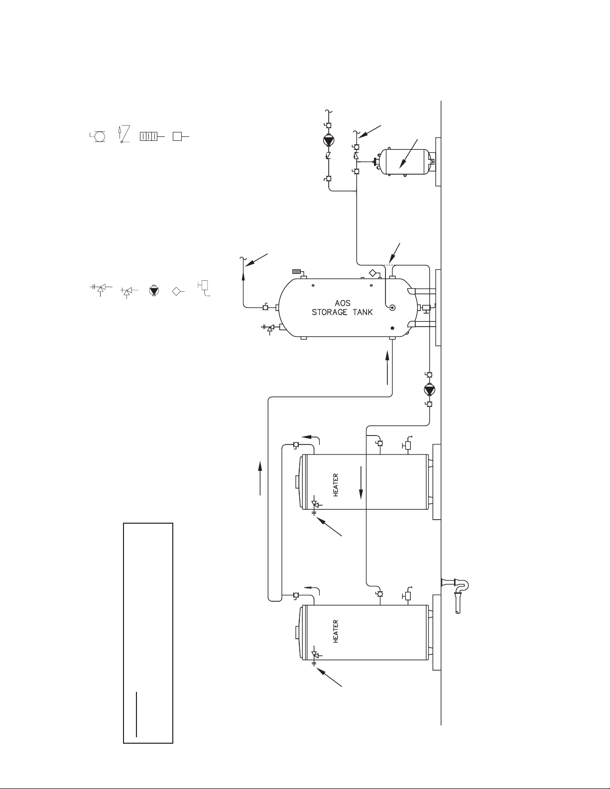
FULL PORT BALL VALV
E
FINISHED
FLOOR
COLD WATER
SUPPLY
HOT WATER
TO FIXTURES
ALTERNATE
COLD WATER
CONNECTION
HOT WATER
RETURN
EXPANSION
TANK
PIPE T&P TO
OPEN DRAIN
PIPE T&P TO
OPEN DRAIN
CHECK VALVE
LEGEND
TEMPERATURE & PRESSURE
RELIEF VALVE
PRESSURE RELIEF VALVE
TEMPERATURE GAGE
CIRCULATING PUMP
WATER FLOW SWITCH
TANK TEMPERATURE CONTROL
DRAIN
WARNING: THIS DRAWING SHOWS SUGGESTED
PIPING CONFIGURATION AND OTHER DEVICES;
CHECK WITH LOCAL CODES AND ORDINANCES
MULTI FLUE - (2 UNITS) WITH VERTICAL STORAGE TANK
FOR ADDITIONAL REQUIREMENTS.
NOTES:
1. Preferred piping diagram.
2. The temperature and pressure relief valve setting shall not exceed pressure rating of any component in the system.
3. Service valves are shown for servicing unit. However, local codes shall govern their usage.
4. The Tank Temperature Control should be wired to and control the pump between the water heater(s) and the storage tank(s).
5. The water heater’s operating thermostat should be set 5 degrees F higher than the Tank Temperature Control.
46
Page 47
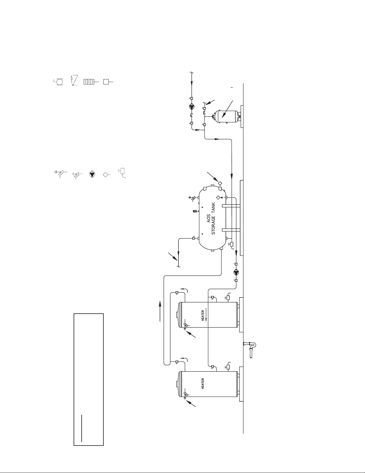
FULL PORT BALL VALV
E
FINISHED
FLOOR
HOT WATER TO FIXTURES
COLD WATER
SUPPLY
HOT WATER
RETURN FROM
FIXTURES
ALTERNATE
LOCATION
EXPANSION
TANK
PIPE T&P TO
OPEN DRAIN
PIPE T&P TO
OPEN DRAIN
CHECK VALVE
TEMPERATURE GAGE
WATER FLOW SWITCH
LEGEND
TEMPERATURE & PRESSURE
RELIEF VALVE
PRESSURE RELIEF VALVE
CIRCULATING PUMP
TANK TEMPERATURE CONTROL
DRAIN
WARNING: THIS DRAWING SHOWS SUGGESTED
PIPING CONFIGURATION AND OTHER DEVICES;
CHECK WITH LOCAL CODES AND ORDINANCES
MULTI FLUE - (2 UNITS) WITH HORIZONTAL STORAGE TANK
FOR ADDITIONAL REQUIREMENTS.
NOTES:
1. Preferred piping diagram.
2. The temperature and pressure relief valve setting shall not exceed pressure rating of any component in the system.
3. Service valves are shown for servicing unit. However, local codes shall govern their usage.
4. The Tank Temperature Control should be wired to and control the pump between the water heater(s) and the storage tank(s).
5. The water heater’s operating thermostat should be set 5 degrees F higher than the Tank Temperature Control.
47
Page 48
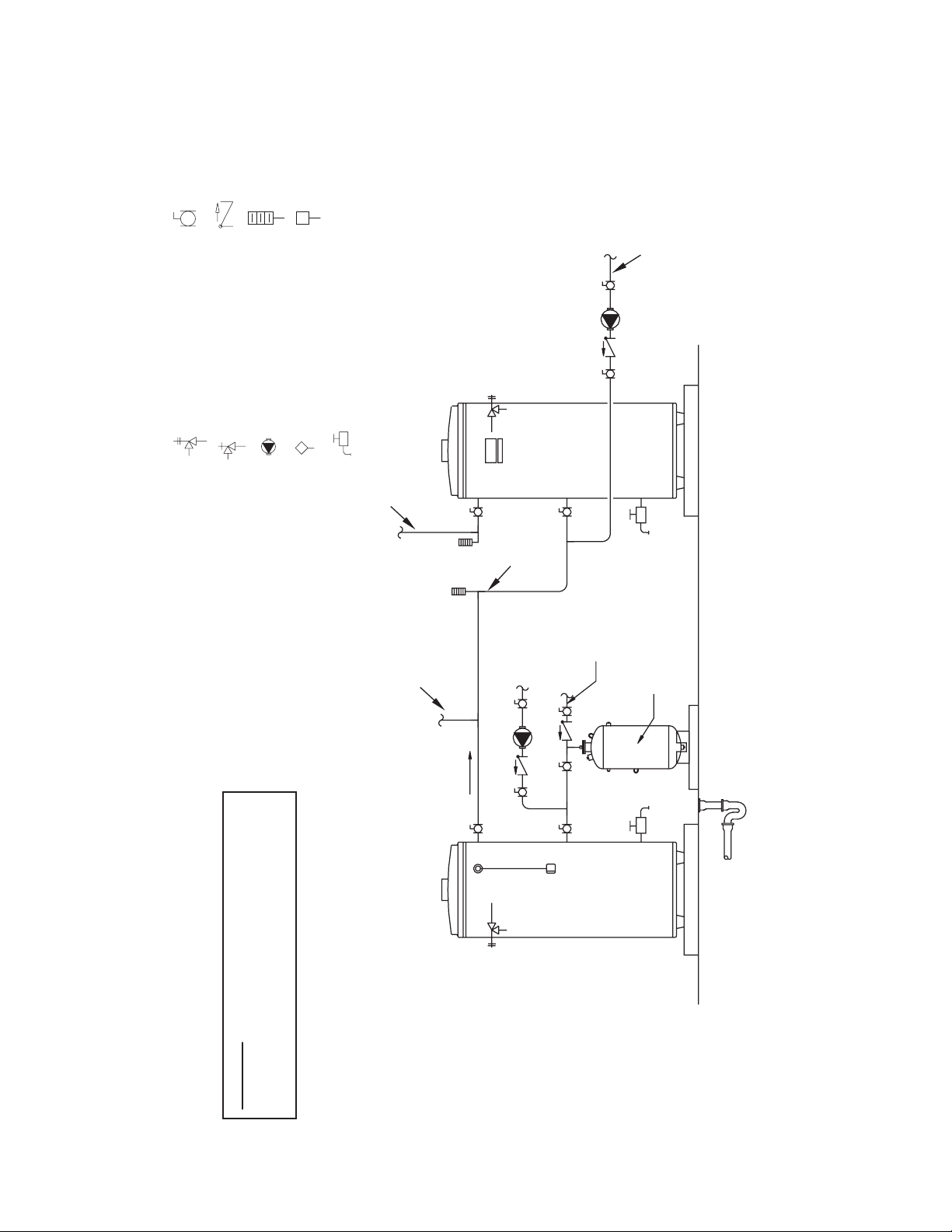
FULL PORT BALL VALV
E
N
BOOSTER WATER
CHECK VALVE
TEMPERATURE GAGE
WATER FLOW SWITCH
LEGEND
BOOSTER WATER RETUR
TEMPERATURE & PRESSURE
RELIEF VALVE
PRESSURE RELIEF VALVE
CIRCULATING PUMP
TANK TEMPERATURE CONTROL
DRAIN
HEATER
BOOSTER
TO FIXTURES
PRE-HEATED
WATER TO
BOOSTER
COLD WATER
SUPPLY
HOT WATER
HOT WATER
TO FIXTURES
RETURN
EXPANSION TANK
1st HEATER
WARNING: THIS DRAWING SHOWS SUGGESTED
PIPING CONFIGURATION AND OTHER DEVICES;
CHECK WITH LOCAL CODES AND ORDINANCES
MULTI FLUE (2 UNITS) TWO TEMPERATURE
FOR ADDITIONAL REQUIREMENTS.
NOTES:
1. Preferred piping diagram.
2. The temperature and pressure relief valve setting shall not exceed pressure rating of any component in the system.
3. Service valves are shown for servicing unit. However, local codes shall govern their usage.
48
Page 49
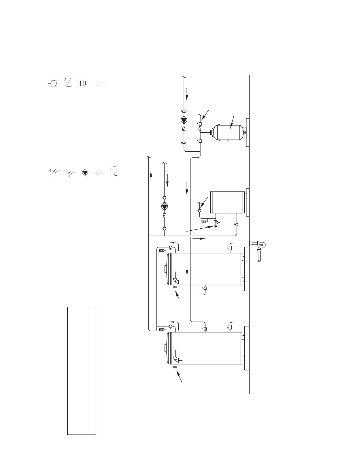
FULL PORT BALL VALV
E
FINISHED FLOOR
HOT OUTLET
R
CHECK VALVE
LEGEND
TEMPERATURE & PRESSURE
RELIEF VALVE
PRESSURE RELIEF VALVE
TEMPERATURE GAGE
WATER FLOW SWITCH
CIRCULATING PUMP
TANK TEMPERATURE CONTROL
DRAIN
AT STORED
TEMPERATURE
HOT WATE
RETURN
BOOSTER RETURN
(IF USED)
BOOSTED
WATER
OUTLET
COLD WATER
SUPPLY
TYPICAL
BOOSTER
EXPANSION
TANK
HEATER
PIPE T&P TO
OPEN DRAIN
PIPE T&P TO
OPEN DRAIN
PRE-HEATER
MUST BE IDENTICAL HEATERS
PRE-HEATER
MULTI FLUE (2 UNITS) WITH BOOSTER TWO TEMPERATURE
WARNING: THIS DRAWING SHOWS SUGGESTED
PIPING CONFIGURATION AND OTHER DEVICES;
CHECK WITH LOCAL CODES AND ORDINANCES
FOR ADDITIONAL REQUIREMENTS.
49
PIPE T&P TO
OPEN DRAIN
NOTES:
1. Preferred piping diagram.
2. The temperature and pressure relief valve setting shall not exceed pressure rating of any component in the system.
3. Service valves are shown for servicing unit. However, local codes shall govern their usage.
Page 50
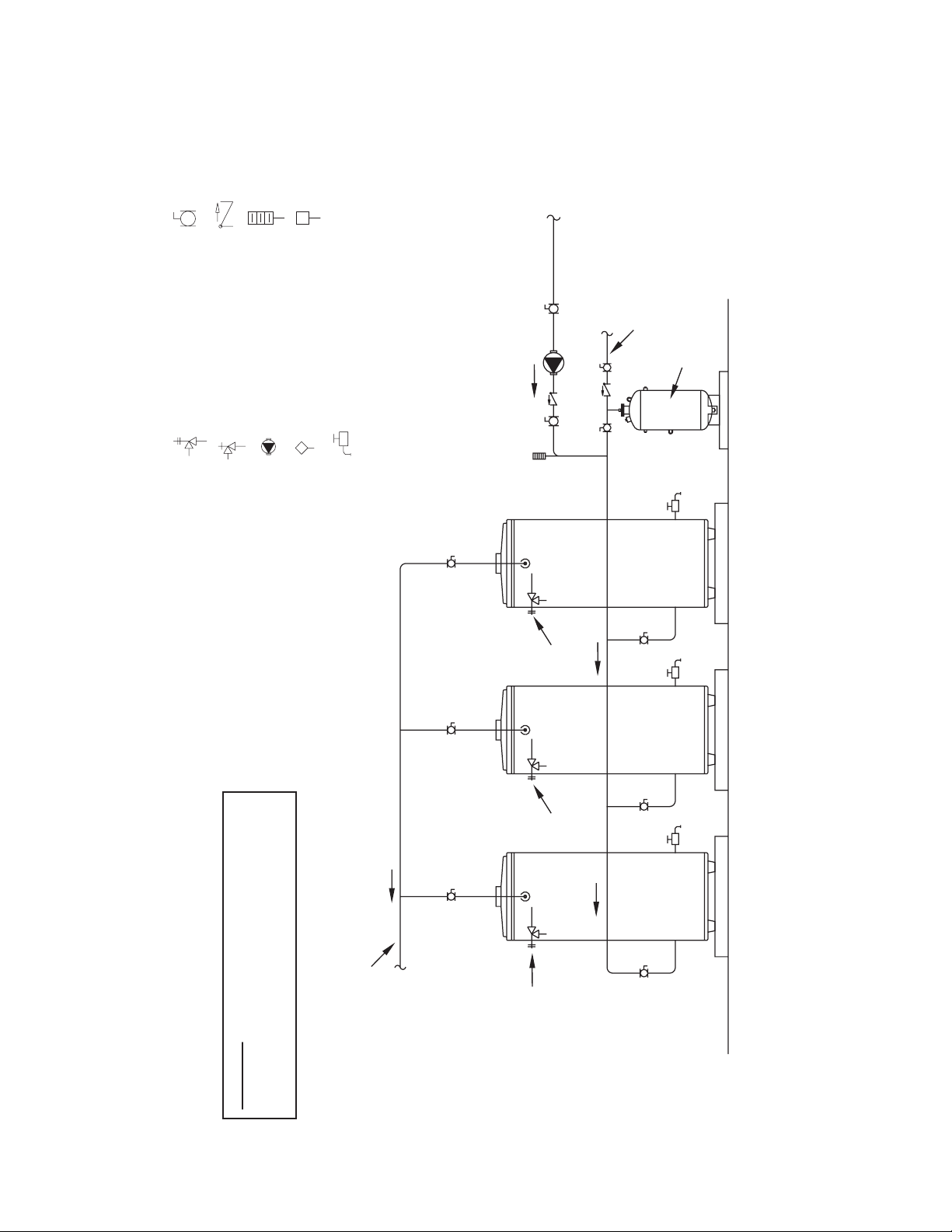
FULL PORT BALL VALV
E
HOT WATER
R
CHECK VALVE
LEGEND
TEMPERATURE & PRESSURE
RELIEF VALVE
PRESSURE RELIEF VALVE
TEMPERATURE GAGE
WATER FLOW SWITCH
CIRCULATING PUMP
TANK TEMPERATURE CONTROL
DRAIN
HOT WATE
RETURN
COLD WATER
SUPPLY
EXPANSION
TANK
PIPE T&P TO
OPEN DRAIN
PIPE T&P TO
TO FIXTURES
WARNING: THIS DRAWING SHOWS SUGGESTED
PIPING CONFIGURATION AND OTHER DEVICES;
CHECK WITH LOCAL CODES AND ORDINANCES
MULTI-FLUE (3 UNITS)
FOR ADDITIONAL REQUIREMENTS.
OPEN DRAIN
PIPE T&P TO
OPEN DRAIN
NOTES:
1. Preferred piping diagram.
2. The temperature and pressure relief valve setting shall not exceed pressure rating of any component in the system.
3. Service valves are shown for servicing unit. However, local codes shall govern their usage.
50
Page 51
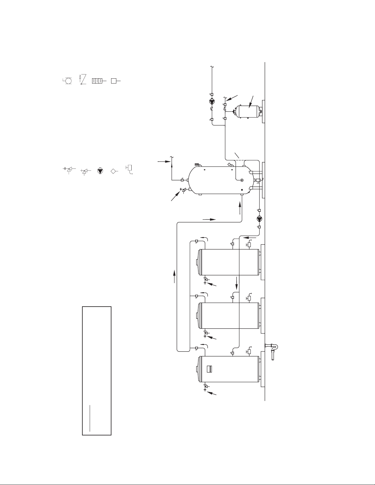
E
TO FIXTURES
HOT WATE
R
HOT WATER
FINISHED FLOOR
RETURN
FULL PORT BALL VALV
CHECK VALVE
TEMPERATURE GAGE
WATER FLOW SWITCH
COLD WATER
SUPPLY
EXPANSION TANK
LEGEND
ALT. COLD WATER
CONNECTION
TEMPERATURE & PRESSURE
RELIEF VALVE
PRESSURE RELIEF VALVE
CIRCULATING PUMP
TANK TEMPERATURE CONTROL
DRAIN
AOS
STORAGE TANK
PIPE T&P TO
OPEN DRAIN
HEATERHEATERHEATER
PIPE T&P TO
OPEN DRAIN
PIPE T&P TO
OPEN DRAIN
PIPE T&P TO
OPEN DRAIN
WARNING: THIS DRAWING SHOWS SUGGESTED
PIPING CONFIGURATION AND OTHER DEVICES;
CHECK WITH LOCAL CODES AND ORDINANCES
MULTI-FLUE (3 UNITS) WITH VERTICAL STORAGE TANK
FOR ADDITIONAL REQUIREMENTS.
NOTES:
1. Preferred piping diagram.
2. The temperature and pressure relief valve setting shall not exceed pressure rating of any component in the system.
3. Service valves are shown for servicing unit. However, local codes shall govern their usage.
4. The Tank Temperature Control should be wired to and control the pump between the water heater(s) and the storage tank(s).
5. The water heater’s operating thermostat should be set 5 degrees F higher than the Tank Temperature Control.
51
Page 52
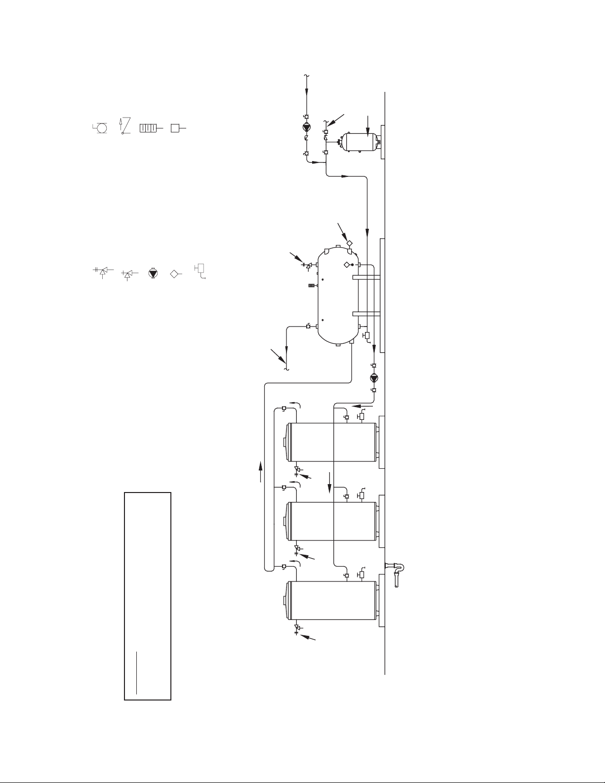
FULL PORT BALL VALV
E
FINISHED FLOOR
EXPANSION TANK
CHECK VALVE
LEGEND
TEMPERATURE GAGE
WATER FLOW SWITCH
HOT WATER
RETURN
COLD WATER
SUPPLY
TEMPERATURE & PRESSURE
RELIEF VALVE
PRESSURE RELIEF VALVE
CIRCULATING PUMP
TANK TEMPERATURE CONTROL
DRAIN
PIPE T&P TO
HOT WATER TO FIXTURES
OPEN DRAIN
HEATERHEATERHEATER
ALTERNATE
LOCATION
AOS
STORAGE TANK
PIPE T&P TO
OPEN DRAIN
PIPE T&P TO
OPEN DRAIN
PIPE T&P TO
OPEN DRAIN
WARNING: THIS DRAWING SHOWS SUGGESTED
PIPING CONFIGURATION AND OTHER DEVICES;
CHECK WITH LOCAL CODES AND ORDINANCES
MULTI-FLUE (3 UNITS) WITH HORIZONTAL STORAGE TANK
FOR ADDITIONAL REQUIREMENTS.
NOTES:
1. Preferred piping diagram.
2. The temperature and pressure relief valve setting shall not exceed pressure rating of any component in the system.
3. Service valves are shown for servicing unit. However, local codes shall govern their usage.
4. The Tank Temperature Control should be wired to and control the pump between the water heater(s) and the storage tank(s).
5. The water heater’s operating thermostat should be set 5 degrees F higher than the Tank Temperature Control.
52
Page 53
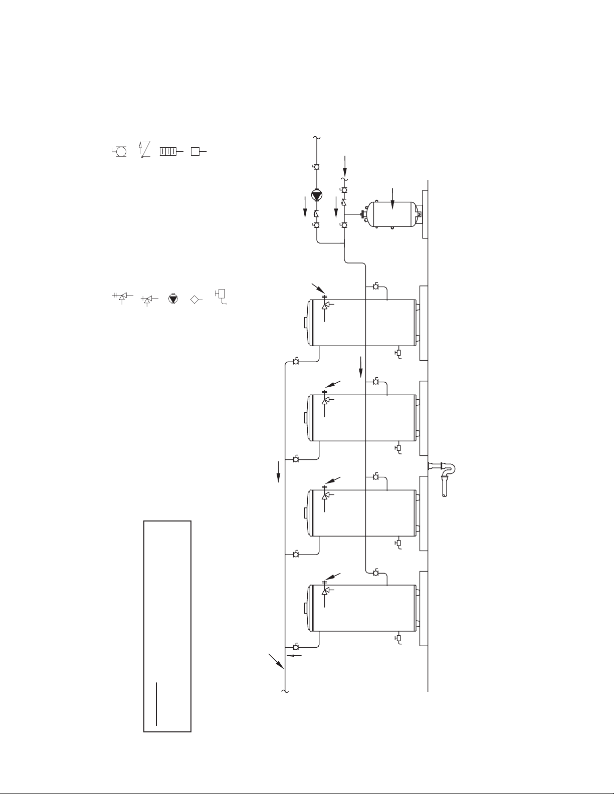
E
HOT WATER
FINISHED FLOOR
HOT WATE
R
FULL PORT BALL VALV
CHECK VALVE
TEMPERATURE GAGE
WATER FLOW SWITCH
RETURN
COLD WATER
SUPPLY
EXPANSION
TANK
LEGEND
TEMPERATURE & PRESSURE
RELIEF VALVE
PRESSURE RELIEF VALVE
CIRCULATING PUMP
TANK TEMPERATURE CONTROL
DRAIN
PIPE T&P TO
OPEN DRAIN
PIPE T&P TO
OPEN DRAIN
PIPE T&P TO
OPEN DRAIN
PIPE T&P TO
OPEN DRAIN
TO FIXTURES
WARNING: THIS DRAWING SHOWS SUGGESTED
PIPING CONFIGURATION AND OTHER DEVICES;
CHECK WITH LOCAL CODES AND ORDINANCES
MULTI FLUE FLUE (4 UNITS)
FOR ADDITIONAL REQUIREMENTS.
NOTES:
1. Preferred piping diagram.
2. The temperature and pressure relief valve setting shall not exceed pressure rating of any component in the system.
3. Service valves are shown for servicing unit. However, local codes shall govern their usage.
53
Page 54

54
Page 55
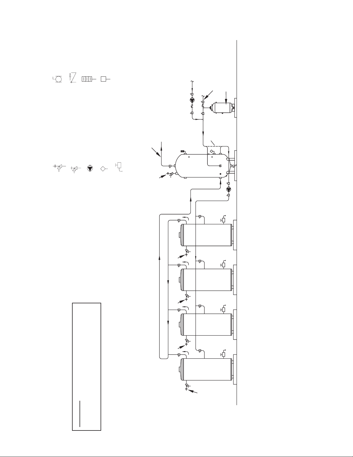
FULL PORT BALL VALV
E
HOT WATER
CHECK VALVE
TEMPERATURE GAGE
WATER FLOW SWITCH
HOT WATER
RETURN
COLD WATER
SUPPLY
EXPANSION
TANK
LEGEND
ALT. COLD
WATER
CONNECTION
TO FIXTURES
TEMPERATURE & PRESSURE
RELIEF VALVE
PRESSURE RELIEF VALVE
CIRCULATING PUMP
TANK TEMPERATURE CONTROL
DRAIN
AOS
STORAGE TANK
PIPE T&P TO
OPEN DRAIN
HEATERHEATERHEATERHEATER
PIPE T&P TO
OPEN DRAIN
PIPE T&P TO
OPEN DRAIN
PIPE T&P TO
OPEN DRAIN
PIPE T&P TO
OPEN DRAIN
MULTI-FLUE (4 UNITS) WITH VERTICAL STORAGE TANK
WARNING: THIS DRAWING SHOWS SUGGESTED
PIPING CONFIGURATION AND OTHER DEVICES;
CHECK WITH LOCAL CODES AND ORDINANCES
FOR ADDITIONAL REQUIREMENTS.
55
NOTES:
1. Preferred piping diagram.
2. The temperature and pressure relief valve setting shall not exceed pressure rating of any component in the system.
3. Service valves are shown for servicing unit. However, local codes shall govern their usage.
4. The Tank Temperature Control should be wired to and control the pump between the water heater(s) and the storage tank(s).
5. The water heater’s operating thermostat should be set 5 degrees F higher than the Tank Temperature Control.
Page 56
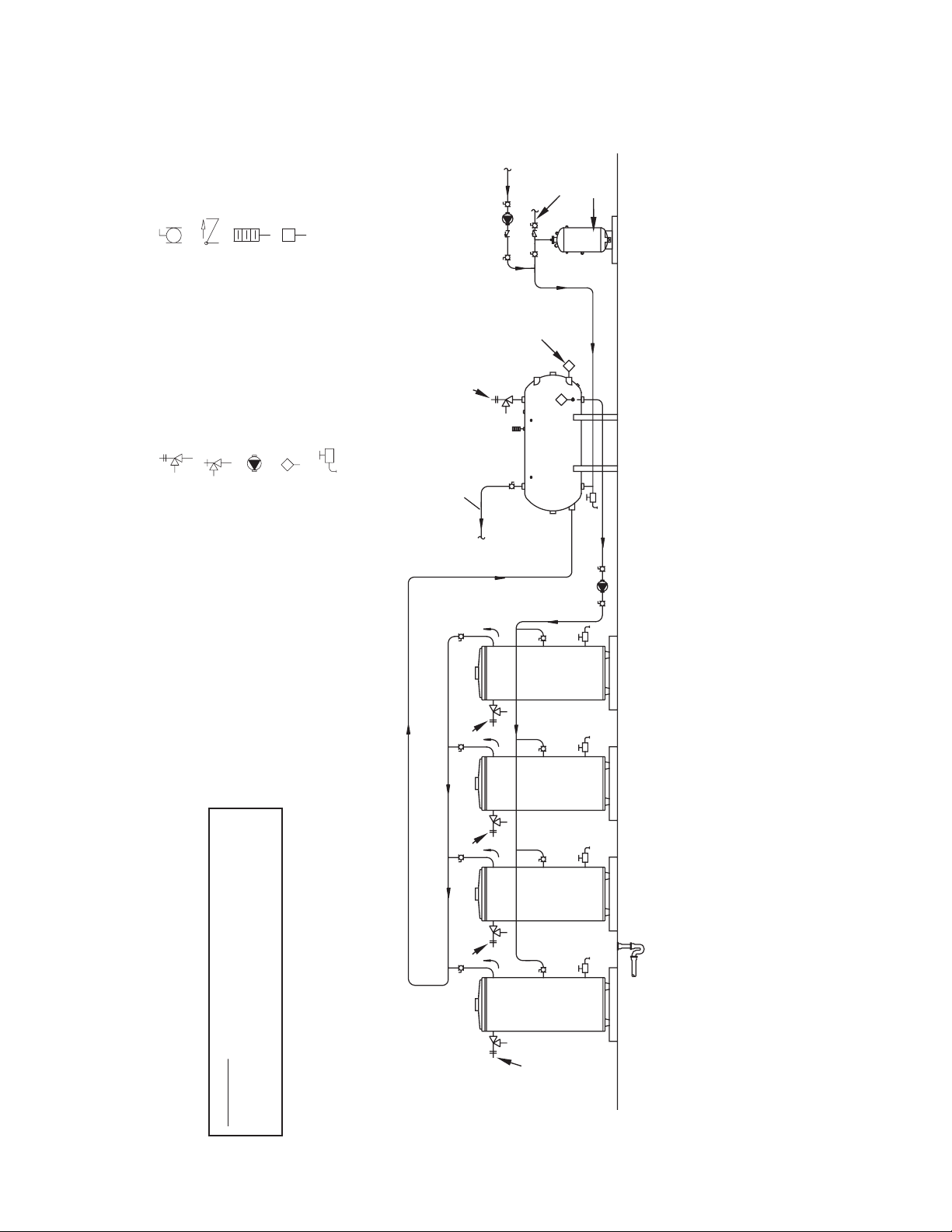
FULL PORT BALL VALV
E
EXPANSION TANK
CHECK VALVE
LEGEND
TEMPERATURE & PRESSURE
RELIEF VALVE
PRESSURE RELIEF VALVE
TEMPERATURE GAGE
WATER FLOW SWITCH
CIRCULATING PUMP
TANK TEMPERATURE CONTROL
DRAIN
HOT WATER
RETURN
PIPE T&P TO
OPEN DRAIN
COLD WATER
ALTERNATE
LOCATION
AOS
SUPPLY
HOT WATER
TO FIXTURES
HEATERHEATERHEATERHEATER
PIPE T&P TO
OPEN DRAIN
PIPE T&P TO
OPEN DRAIN
STORAGE TANK
MULTI-FLUE (4 UNITS) WITH HORIZONTAL STORAGE TANK
WARNING: THIS DRAWING SHOWS SUGGESTED
PIPING CONFIGURATION AND OTHER DEVICES;
CHECK WITH LOCAL CODES AND ORDINANCES
FOR ADDITIONAL REQUIREMENTS.
PIPE T&P TO
OPEN DRAIN
56
PIPE T&P TO
OPEN DRAIN
NOTES:
1. Preferred piping diagram.
2. The temperature and pressure relief valve setting shall not exceed pressure rating of any component in the system.
3. Service valves are shown for servicing unit. However, local codes shall govern their usage.
4. The Tank Temperature Control should be wired to and control the pump between the water heater(s) and the storage tank(s).
5. The water heater’s operating thermostat should be set 5 degrees F higher than the Tank Temperature Control.
Page 57

57
Page 58
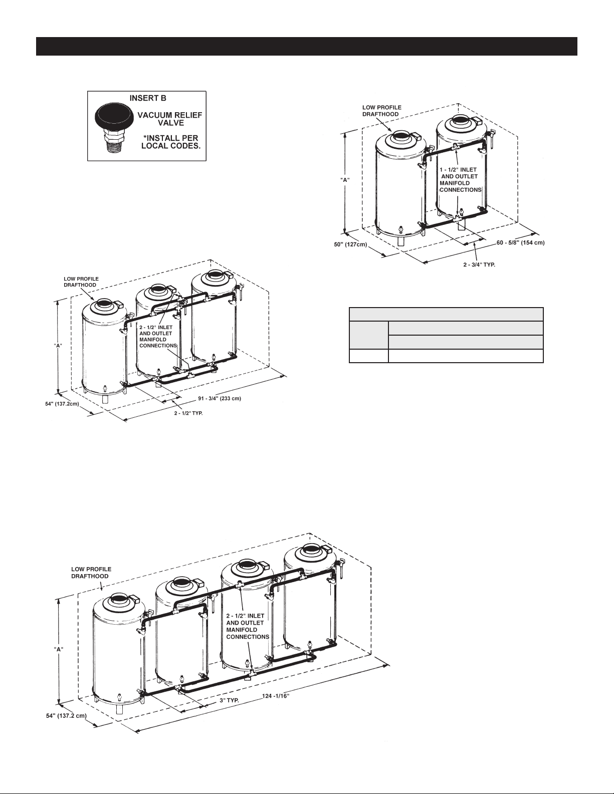
Figure 32. Vacuum Relief Valve
MANIFOLD KITS
Figure 33. Two-Unit Manifold Kit (100109228)
Table 12. Rough-In Dimensions
Dimensions "A" Inches (cm)
Models
154 67.50” (171cm)
Low Prole Vertical Hood "A"
Figure 34. Three-Unit Manifold Kit (100109229)
Figure 35. Four-Unit Manifold Kit (100109230)
58
Page 59

NOTES
59
Page 60

Copyright © 2019. All rights reserved.
 Loading...