


™
OWNERS MANUAL
NOTICE D’UTILISATION MANUAL DEL USUARIO
Model No.
Modèle No.
Modelo No.
45-04631
CAUTION: Read Rules for Safe Operation and Instructions Carefully
ATTENTION: Lire et suivre attentivement les instructions et consignes de sécurité de cette notice.
PRECAUCION: Lea cuidadosamente los Procedimientos e Instrucciones para la Operación Segura de la Máquina.
130 LB. Tow Spreader
ÉPANDEUR REMORQUÉ DE 130 LB. (59 KG) ESPARCIDOR DE REMOLQUE DE 130 LBS. (59 KG)
• |
Safety |
• |
Sécurité |
• |
Seguridad |
• |
Assembly |
• |
Assemblage |
• |
Montaje |
• |
Operating |
• |
Utilisation |
• |
Operación |
• |
Maintenance |
• |
Entretien |
• |
Mantenimiento |
• |
Repair Parts |
• |
Pièces |
• |
Piezas de repuesto |
Want more information or assembly tips? Scan with free ShowUHow Mobile App available at iTunes Store or Android Market.
Call 1-800-448-9282 for missing parts or assembly help.


 the fastest way to purchase parts www.speedepart.com
PRINTED IN USA |
FORM NO. 42313 rev. (1/3/12) |
SAFETY RULES
Remember, any power equipment can cause injury if operated improperly or if the user does not understand how to operate the equipment. Exercise caution at all times when using power equipment.
Look for this symbol to point out important safety precautions. It means —
ATTENTION! Become alert! Your safety is involved.
CAUTION: vehicle braking and stability may be affected with the addition of an accessory or an attachment. Be aware of changing conditions on slopes.
•Read the towing vehicle owners manual and towing vehicle safety rules. Know how to operate your tractor before using the broadcast spreader attachment.
•Read the chemical label instructions and cautions for handling and applying the chemicals purchased for spreading.
•Wear eye and hand protection when handling and when applying lawn or garden chemicals.
•Never operate tractor and spreader attachment without wearing substantial footwear, and do not allow anyone to ride or sit on spreader attachment frame.
•Never allow children to operate the tractor or spreader attachment, and do not allow adults to operate without proper instructions.
•Always begin with the transmission in first (low) gear and with the engine at low speed, and gradually increase speed as conditions permit. Maximum towing speed - 6 M.P.H.
•When towing broadcast spreader do not drive too close to a creek or ditch and be alert for holes and other hazards which could cause you to loose control of the broadcast spreader and tractor.
•Before operating vehicle on any grade (hill) refer to the safety rules in the vehicle owner's manual concerning safe operation on slopes. Stay off steep slopes!
•Follow maintenance and lubrication instructions as outlined in this manual.
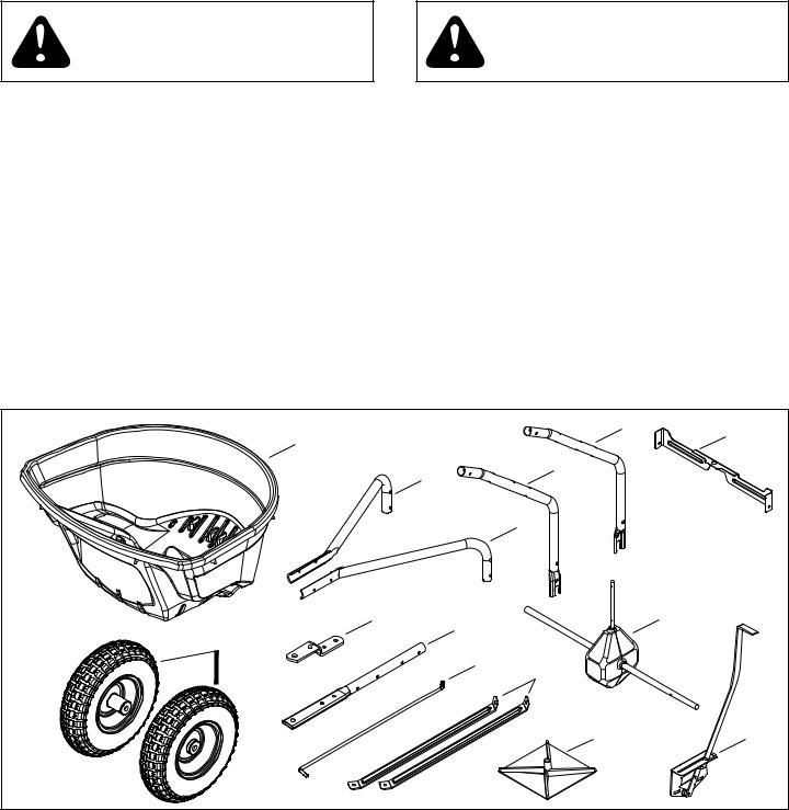
CARTON CONTENTS
|
|
|
|
6 |
7 |
1 |
|
|
|
|
|
|
|
|
|
|
|
|
3 |
|
5 |
|
|
|
|
|
|
|
|
|
|
|
4 |
|
|
8 |
|
9 |
|
|
13 |
|
|
|
|
|
|
2 |
|
|
|
|
|
|
|
10 |
11 |
|
|
|
|
|
|
|
|
|
|
|
12 |
|
14 |
REF |
QTY |
PART NO |
DESCRIPTION |
REF |
QTY |
PART NO |
DESCRIPTION |
1 |
1 |
41084 |
Hopper |
8 |
1 |
23687 |
Bracket, Hitch |
2 |
2 |
40880 |
Wheels |
9 |
1 |
41937 |
Tube, Hitch |
3 |
1 |
42009 |
Tube, Hitch Support |
10 |
1 |
41930 |
Flow Control Rod |
4 |
1 |
42008 |
Tube, Hitch Support |
11 |
2 |
27312 |
Hopper Brace |
5 |
1 |
42311 |
Tube, Hopper Support |
12 |
1 |
04367 |
Spreader Impeller |
6 |
1 |
42312 |
Tube, Hopper Support |
13 |
1 |
- - - - - |
Axle/Gearbox Assembly |
7 |
1 |
27313 |
Cross Brace |
14 |
1 |
- - - - - |
Flow Control Assembly |
2
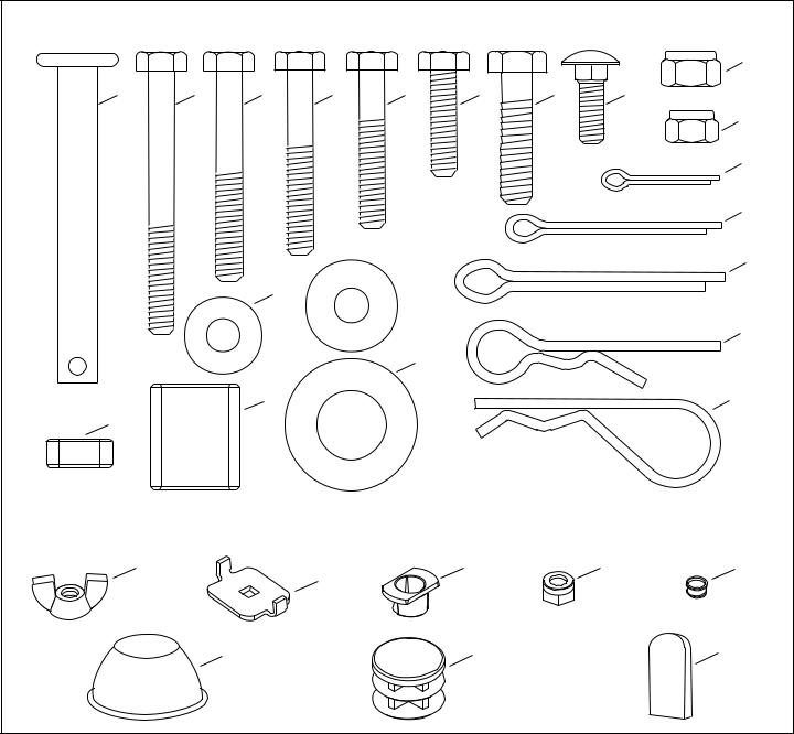
SHOWN FULL SIZE
I
A |
B |
C |
D |
E |
F |
G |
H |
J
P
Q
 N R
N R
M
S
O
L T
K
NOT SHOWN FULL SIZE
U |
W |
X |
Y |
|
V |
|
|
Z |
AA |
|
BB |
HARDWARE PACKAGE
REF |
QTY |
PART NO |
DESCRIPTION |
REF |
QTY |
PART NO |
DESCRIPTION |
A |
1 |
47623 |
Hitch Pin |
O |
4 |
R19212016 |
Washer, 5/8" |
B |
2 |
49870 |
Hex Bolt, 1/4" x 2-1/2" |
P |
1 |
44101 |
Cotter Pin, 3/32" x 3/4" |
C |
2 |
46699 |
Hex Bolt, 1/4" x 2" |
Q |
1 |
43093 |
Cotter Pin, 1/8" x 1-1/2" |
D |
6 |
1509-69 |
Hex Bolt, 1/4" x 1-3/4" |
R |
1 |
46855 |
Cotter Pin, 3/16" x 2" |
E |
2 |
43648 |
Hex Bolt, 1/4" x 1-1/2" |
S |
1 |
48934 |
Hairpin, Agitator |
F |
1 |
43661 |
Hex Bolt, 1/4" x 1" |
T |
1 |
43343 |
Hairpin Cotter |
G |
2 |
43840 |
Hex Bolt, 5/16" x 1-1/4" |
U |
1 |
47141 |
Wing Nut |
H |
1 |
49950 |
Carriage Bolt, 1/4" x 3/4" |
V |
1 |
24858 |
Adjustable Stop |
I |
2 |
47810 |
Hex Nut, 5/16" Nylock |
W |
2 |
40315 |
Bearing, Flat Sided |
J |
13 |
47189 |
Hex Nut, 1/4" Nylock |
X |
1 |
44285 |
Hopper Bushing |
K |
1 |
23625 |
Spacer |
Y |
1 |
741-0475 |
Bushing, 3/8" Plastic |
L |
2 |
48857 |
Spacer |
Z |
2 |
48499B |
Hub Cap |
M |
9 |
43088 |
Washer, 1/4" |
AA |
3 |
49449 |
Plug |
N |
5 |
1543-69 |
Washer, Nylon |
BB |
1 |
43848 |
Grip |
3
ASSEMBLY INSTRUCTIONS
TOOLS REQUIRED FOR ASSEMBLY
(1)Hammer
(1)Pliers
(2)7/16" Wrenches
(2)1/2" Wrenches
Lay out and identify parts and hardware using the illustrations on pages 2 and 3.
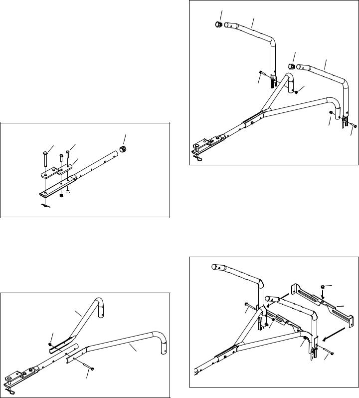
STEP 1: (SEE FIGURE 1)
•Insert a plug (AA) into the end of the hitch tube (9).
•Attach the hitch bracket (8) to the hitch tube using two 5/16" x 1-1/4" hex bolts (G) and 5/16" nylock nuts (I).
Tighten.
•Install the hitch pin (A) in the hitch bracket and hitch tube and secure it with the hairpin cotter (T).
AA
A G
8
 9
9


 I
I


 T
T
FIGURE 1
STEP 2: (SEE FIGURE 2)
•Attach the hitch support tubes (3), and (4) to the hitch tube using one 1/4" x 2" hex bolt (C) and 1/4" nylock nut (J). Do not tighten completely.
3 |
J |
4 |
C |
FIGURE 2
STEP 3: (SEE FIGURE 3)
•Insert plugs (AA) into the ends of the hopper support tubes (5) and (6).
•Attach hopper support tube (5) and hopper support tube (6) to the hitch support tubes as shown, using two 1/4" x 1-1/2" hex bolts (E) and 1/4" nylock nuts (J).
Do not tighten completely.
AA |
|
5 |
|
|
AA |
|
6 |
E |
J |
|
|
|
J |
|
E |
FIGURE 3
STEP 4: (SEE FIGURE 4)
•Insert the bushing (Y) into the cross brace (7).
•Attach the cross brace to the hopper support tubes using two 1/4" x 2-1/2" hex bolts (B) and 1/4" nylock nuts (J). Do not tighten completely.
Y |
7 |
B |
J |
J |
B |
FIGURE 4
4
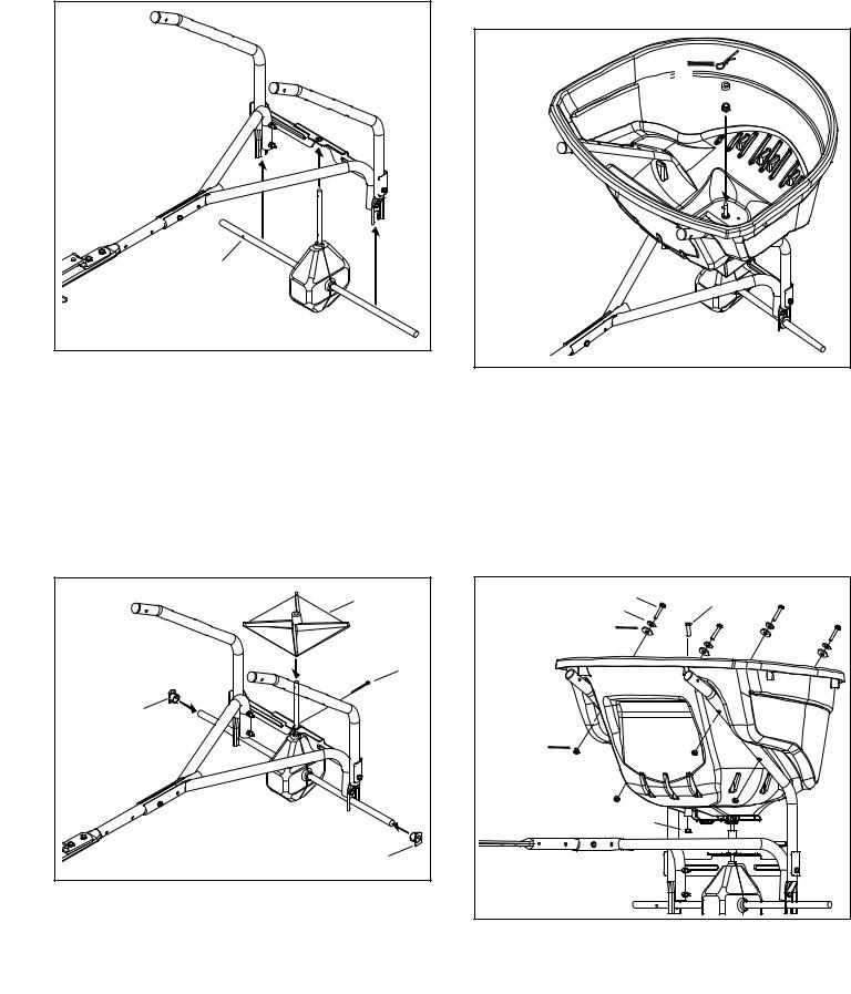
STEP 5: (SEE FIGURE 5)
•Install the gearbox by inserting the end of the verticle shaft into the cross brace bushing and inserting the axle into the ends of the hopper support tubes. Be sure the hole in the axle is located on the side shown in figure 5.
hole on this end |
FIGURE 5
STEP 6: (SEE FIGURE 6)
•Slide the flat sided bearings (W) onto the axle and insert them into the ends of the hopper support tubes.
•Slide the spreader impeller (12) onto the spreader shaft and secure it with a 1/8" x 1-1/2" cotter pin (Q).
12 |
Q |
W |
W |
FIGURE 6
STEP 7: (SEE FIGURE 7)
•Place the hopper on the hopper support tubes, inserting the spreader shaft up through the square hole in the bottom of the hopper.
•Slide the hopper bushing (X) onto the spreader shaft and insert it into the bottom of the hopper.
•Slide the spacer (K) onto the spreader shaft.
•Install the agitator hairpin (S) in the spreader shaft.
S
 K
K 
X 

FIGURE 7
STEP 8: (SEE FIGURE 8)
•Attach the hopper to the hopper support tubes using four 1/4" x 1-3/4" hex bolts (D), 1/4" washers (M), nylon washers (N) and 1/4" nylock nuts (J). Make only finger tight.
•Insert the 1/4" x 1" hex bolt (F) into the hole in the bottom of the hopper, pressing the head of the bolt into the hex shaped recess of the hole. Install a 1/4" nylock nut (J) onto the bolt and tighten.
M |
D |
F |
|
||
|
|
|
N |
|
|
J |
|
|
|
|
J |
FIGURE 8
5

STEP 9: (SEE FIGURE 9)
•Install the grip (BB) onto the flow control arm.
•Assemble the adjustable stop (V) to the flow control bracket using the 1/4" x 3/4" carriage bolt (H), nylon washer (N) and wing nut (U).


 BB
BB
STEP 11: (SEE FIGURE 11)
•Install the end of the flow control rod (10) with no hole into the elongated hole in the flow plate on the bottom of the hopper. Lock the rod in the flow plate by rotating the rod.
U
N 

V |
H |
FIGURE 9
FIGURE 11
STEP 10: (SEE FIGURE 10)
•Attach the flow control bracket to the hitch tube using two 1/4" x 1-3/4" hex bolts (D), four 1/4" washers (M) and two 1/4" nylock nuts (J). Do not tighten completely.
J |
M |
M |
D |
FIGURE 10
STEP 12: (SEE FIGURE 12)
•Swing the flow control rod around and insert the end of the rod into the flow control arm. Secure it with a
1/4" washer (M) and a 3/32" x 3/4" cotter pin (P).
P |
FIGURE 12
6
 Loading...