

Agria 2100 Operating Instructions Manual
Before commissioning the machine, read operating
instructions and observe warnings and safety instructions.
Operating Instructions No.
998 705-A 12.07
3220
&
Single-Wheel Power HoeSingle-Wheel Power Hoe
Single-Wheel Power HoeSingle-Wheel Power Hoe
Single-Wheel Power Hoe
21002100
21002100
2100
OperatingOperating
OperatingOperating
Operating
InstructionsInstructions
InstructionsInstructions
Instructions
2 Single-wheel power hoe 2100
Symbols, Name Plate
Please complete:
Maschine T ype No.:............................
ID/Machine No.:
..........................................................
Engine T ype:......................................
Engine No.: ........................................
Date of Purchase: .........................
For name plate, refer to p3/fig. B/20.
For engine number, refer to p3/fig.
B/24.
Please state these data when order-
ing spare parts to avoid wrong deliveries.
Only use original agria spare parts!
Specifications, figures and dimensions stated in these instructions are
not binding. No claims can be derived
from them. We reserve the right for
improvements without changing these
instructions.
This delivery comprises:
Operating instructions
Single-wheel hoe
– basic machine
– handlebar with tensioning lever
Tool kit
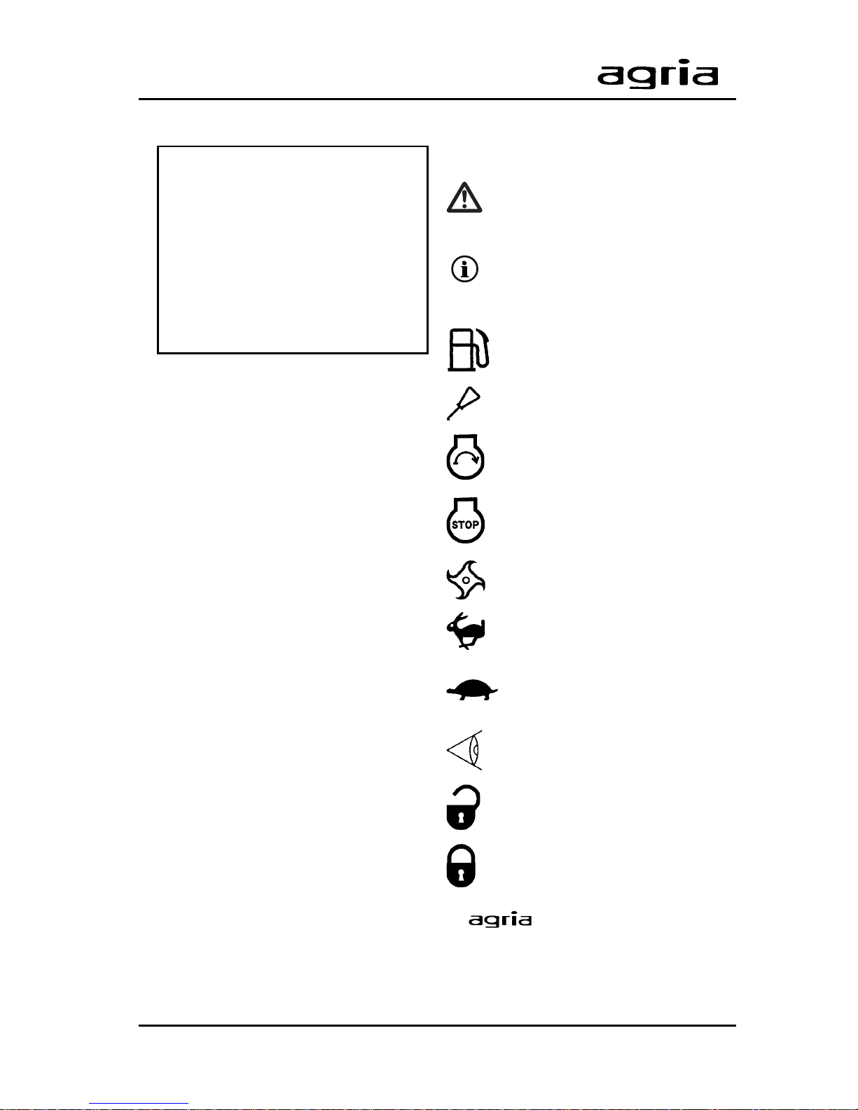
Symbols
Warning – Danger
Important information
Fuel
Oil
Engine Start
Engine Stop
Hoeing/tilling drive
Fast
Slow
Visual check
Open (unlocked)
Closed (locked)
-
Service
= contact Your agria workshop
Single-wheel power hoe 2100 3
A
B
24
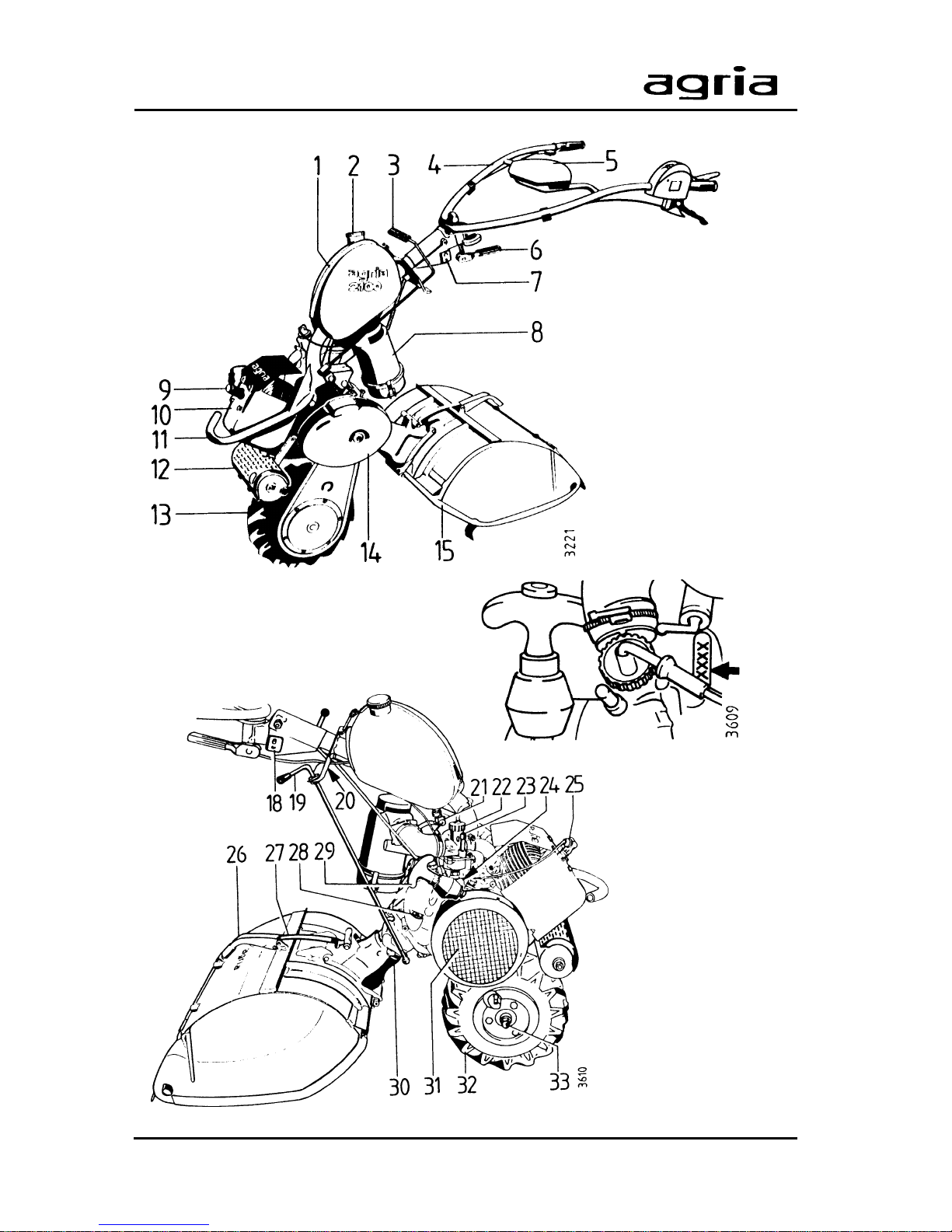
Designation of Parts

4 Single-wheel power hoe 2100
Designation of Parts
Figure A and B
1 Fuel tank
2 Fuel tank cap
3 Gear shift lever
4 Handlebar
5 Tool kit
6 Tensioning lever for handlebar side adjustment
7 Hexagonal screw for handlebar height adjustment
8 Oil bath air filter
9 Spark plug
10 Cooling-air baffle
11 Location for front weight mounting and engine hoop guard
12 Exhaust
13 Drive-wheel
14 Cap for clutch and chain gear housing
15 Tilling attachment
18 Square nut for handlebar height adjustment
19 Shift lever for tilling drive
20 Name plate/ID No.
21 Fuel tap
22 Carburetor
23 Carburetor - tickler
24 Engine No.
25 Spark plug/spark plug connector
26 Tensioning lever for protective hood
27 Tensioning spring for protective hood
28 Mechanical gearbox – oil filler screw/oil control screw
29 Starter handle
30 Tilling drive
31 Cooling-air screen
32 Drive-wheel
33 Hexagonal nut for drive-wheel
Single-wheel power hoe 2100 5
Index
Amount of Delivery ................. 2
Designation of Parts .......... 3, 46
Assembly Instructions ...........
6
1. Safety Instructions........ 7 - 11
2. Specifications
Dimensions ..................................... 12
Power Hoe ...................................... 12
Tilling Drive ..................................... 12
Noise Level ..................................... 12
Vibration Acceleration Value......... 12
Engine............................................. 13
Operation on Slopes....................... 13
3. Devices and
Operating Elements
Engine............................................. 14
Safety Circuit .................................. 15
Clutch.............................................. 16
Gearbox .......................................... 16
Steering Handle .............................. 17
Tilling Tools ..................................... 18
Drive-Wheels .................................. 19
Front Weight.................................... 19
Leaf Deflector ................................. 20
4. Commissioning and
Operation
Commissioning the Machine .......... 22
Starting the Engine ......................... 23
Tilling .............................................. 24
Change of work-site........................ 25
Switching off the Engine................. 26
Ridging............................................ 27
5. Maintenance
Engine............................................. 28
Mechanical Gearbox ...................... 31
Tilling Drive .................................... 32
Adjustments on Hand Levers ........ 34
General Maintenance ..................... 36
Cleaning.......................................... 36
Storage ........................................... 37
Recommendations
Lubricants, Anti-Corrosive Agents 38
Fuel ................................................. 38
Maintenance and Repair ................ 38
6. Troubleshooting ............ 40 -41
Varnishes, Wear Parts ........... 42
Diagram: Electric Circuit ....... 43
Maintenance Chart.................4 3
Inspection and
Maintenance Chart................. 44
Conformity Declaration ......... 47
Note fold-out pages!
Fig. A + B
........................................ 3
Fig. C ............................................. 46
6 Single-wheel power hoe 2100
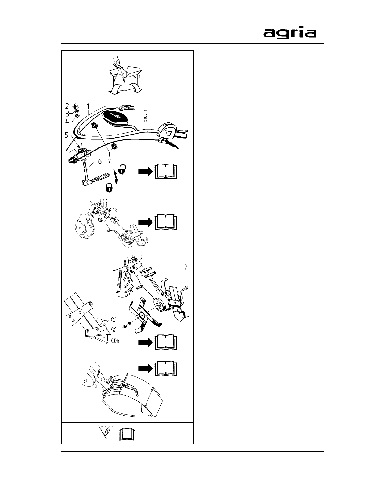
Instructions for Unpacking
Instructions for
Unpacking and Assembl y
Open top of cardboard box.
Mount handlebar
- Unscrew hexagonal screws (3 + 4).
- Place handlebar (1) onto locking disk
and hold
- make sure that bowden cables and
electric cables are not twisted or
squeezed.
- Insert threaded bolt (6) of tensioning
lever into steering bar joint and handlebar . Push threaded bolt in from below.
- Move tensioning lever to the left and
screw hexagonal n ut (4) onto threaded
bolt until hexagonal nut fits into triangular relief on handlebar.
- Move tensioning lever backwards to
centre position and press down (tension). Now the handlebar must be
firmly jammed with steering bar. If this
is not the case, screw hexagonal nut
(4) further down (for adjusting
tensioning lever, refer to page 34).
- If handlebar jamming is not sufficient,
screw hexagonal nut (3) onto bolt and
lock with hexagonal nut (4).
- Place nut cap (2).
- Fasten bowden cables and electrical lines
with clamps (7) onto handlebar rods.
Mount tilling shaft (refer to page 17).
Mount tilling tools and hoeing skid
(refer to page 18).
Mount protective hood (ref er to page
18).
Carry out all steps for starting-up
and Assembly
17
18
34
18

Single-wheel power hoe 2100 7
1. Safety Instructions
Before starting the engine, read the operating instructions and note:
W arning
This symbol marks all paragraphs aff ecting your safety. Pass all safety instructions to other users and operators.
Due Use
The single-wheel power hoe and the
mounted implements authorized by the
manufacturer ha ve been designed for all
common applications and tasks in farming and forestry, horticulture and park
maintenance (due use).
Any other type of use is considered undue. The manufacturer is not liable for
any damages resulting from undue use,
for which the risk lies with the user alone.
Due use includes compliance with
manufacturer’s instructions on operation, maintenance and repair.
Any unauthorized changes to the single-wheel power hoe render manufacturer liability null and void.
General Instructions
on Safety and
Accident Prevention
Basic Rule:
The standard accident prev ention regulations must be adhered to, as well as
all other generally accepted rules governing operational safety, occupational
health and road traffic regulations.
For travelling on public roads, the current traffic code applies.
Check the single-wheel power hoe for
road and operational safety each time
you take up operation.
Only persons familiar with the singlewheel power hoe and instructed on the
hazards of operation are allowed to use,
maintain and repair the machine.
Teenagers of 16 years or younger may
not operate the single-wheel power hoe!
Only work in good light and visibility.
Operator’ s clothes should fit tight. A void
wearing loose fitting clothes. Wear solid
shoes.
Note the warning and instruction signs
on the single-wheel power hoe for safe
operation. Compliance is for your own
safety.
When transporting the single-wheel
power hoe on vehicles or trailers outside the area to be cultivated, ensure
that the engine is turned off.
Careful with rotating tools – keep at a
safe distance!
1

8 Single-wheel power hoe 2100
1. Safety Instructions
Beware of coasting tools. Before you
start any maintenance or repair on them,
wait until tools have come to a complete
stop.
Foreign powered parts shear and crush!
Riding on the attachment during opera-
tion is not permitted.
Attachments and their weight affect the
driving, steering, braking, and tip-over
characteristics of the single-wheel power
hoe. Therefore, ensure steering and
braking functions are sufficient. Match
operating speed to conditions.
Do not change governor settings. High
engine speed increases risk of accidents.
Working Area and
Dangerous Area
The user is liable to third parties working within the single-wheel power hoe’s
working range.
Staying in the hazardous area of the single-wheel power hoe is not permitted.
Check the immediate surroundings of
the single-wheel power hoe before you
start it. Watch out for children and animals.
Before you start work, clear the area
from any foreign object. Dur ing operation, always w atch out for further objects
and remove them in time.
For operation in enclosed areas , ensure
that a safety distance is kept to enclosures to prevent damage to tools.
Operation and
Safety Devices
Before you start operation
Become familiar with the devices and
operating elements and their functions.
Above all, learn how to turn off the engine quickly and safely in case of an
emergency.
Ensure that all protective devices are
mounted and positioned to provide protection.
With no attachment mounted, make sure
PTO-shaft is covered with the protective cap.
Starting the engine
Do not start engine in closed rooms. The
carbon monoxide contained in the exhaust fume is extremely toxic when inhaled.
Before y ou start the engine set all operating elements to neutral or idling position.
For starting the engine, do not step in
front of the single-wheel power hoe and
the attachment.
Operation
Never leave the operator’s position at
the steering handle while single-wheel
power hoe is at work.
Never adjust the steering handles during work – danger!
1

Single-wheel power hoe 2100 9
1. Safety Instructions
For any operation do not leave the operator’ s position as defined by the steering handle, especially not when you turn
the machine.
Riding on the attachment during operation or in transport is not permitted.
If clogging occurs in the attachment, turn
off the engine and clean the attachment
with an appropriate tool.
In case of damage to the single-wheel
power hoe or to the attachment, immediately turn off the engine and have it
repaired.
If steering causes problems, immediately bring the single-wheel power hoe
to a halt and turn it off. Have the malfunction removed without delay.
To prevent the single-wheel power hoe
from sliding on slopes make sure it is
secured by another person using a bar
or a rope. This person must be located
at a higher position than the vehicle at a
safe distance from the attachment at
work.
If possible, always work horizontally to
the slope.
End of Operation
Nev er leave the single-wheel power hoe
unattended with the engine running.
Before you lea ve the single-wheel power
hoe, turn off the engine. Then close fuel
tap.
Secure single-wheel power hoe against
unauthorized use – remove spark plug
connector.
Attachments
Only mount attachments with the engine
and attachment drive switched off.
Always use appropriate tools and wear
gloves when changing attachments and
parts thereof.
For mounting and dismounting attachments bring support leg into proper position and ensure stability.
Secure single-wheel power hoe and attachments against rolling off (wheel
wedge).
Beware of injuries when coupling attachments. Proceed with extreme caution.
Mount attachments as specified and
only couple at specified points.
Secure single-wheel power hoe and attachment against unauthorized use and
rolling off when you leave the machine.
If necessary, install transport or security devices and secure.
Hoeing Attachment
Adjust protective hood of hoeing attachment so that only those parts of tools
which penetrate the soil are not covered.
When hoeing, make sure hoeing skid is
adjusted properly.
1

10 Single-wheel power hoe 2100
1. Safety Instructions
Maintenance
Never carry out any maintenance or
cleaning with the engine running.
In addition, always remove spark plug
connector before you work on the engine.
Check regularly and, if necessary, replace all protecting devices and tools
subject to wear and tear.
Replace damaged cutting tools.
Always wear safety gloves and use
proper tools when exchanging cutting
tools.
Do not carry out repairs like welding,
grinding, drilling, etc. on structural and
safety-relevant parts (e.g. coupling devices)!
Keep single-wheel power hoe and attachment clean to avoid risk of fire.
Check nuts and scre ws regularly for tight
fit and re-tighten, if necessary.
Ensure that you re-install all safety and
protective devices and adjust them properly after maintenance and cleaning.
Only use original agria spare parts. All
other commercial spare parts must correspond to quality and technical requirements specified by agria.
Storage
It is not allowed to store the single-wheel
power hoe in rooms with open heating.
Never park the single-wheel pow er hoe
in closed rooms with fuel left in tank. Fuel
vapours are hazardous.
Engine, Fuel, and Oil
Never let the engine run in closed rooms .
Extreme danger of intoxication!
Careful when dealing with fuel. Great
danger of fire! Never refill fuel close to
open fire, inflammable sparks or hot engine parts. Do not refill fuel in closed
rooms. Do not smoke when refilling!
Refill only with the engine switched off
and cooled down.
Do not spill any fuel, use a proper filling
device.
In case of fuel-spillage, push the singlewheel power hoe away from the spillage before you start the engine.
Make sure fuel is of specified quality.
Store fuel in approved cans only.
Store anti-corrosive agents and stabi-
lizing liquids out of reach of children. If
sickness and vomiting occur , see a doctor . If fuel has contacted ey es, rinse them
thoroughly, avoid inhaling of vapours.
Read and observe enclosed instructions.
Before you dispose of opened and
seemingly empty pressurised tins make
sure they are completely empty. Empty
them in ventilated places saf e from spark
formation or flames. If necessary, dispose of tins in hazardous waste deposits.
1
Single-wheel power hoe 2100 11
1. Safety Instructions
Careful when draining hot oil, danger of
burns.
Make sure oil used is of specified quality. Storage is in approved cans only.
Dispose of oil, greases, and filters
seperately and properly.
Tyres and
Tyre Air Pressure
When working on tyres, make sure single-wheel power hoe is parked properly
and secured against rolling off.
Any repairs are to be carried out by
trained mechanics only and with the appropriate tools.
Regularly check tyre air pressure. Excessive air pressure may cause bursts.
Use appropriate tyre air pressure when
mounting front weight.
Re-tighten fastening screws of drivewheels or check tightness when doing
maintenance work.
Electrical System and
Battery
Persons having a pacemaker may not
touch live parts of the ignition system
when the engine is running.
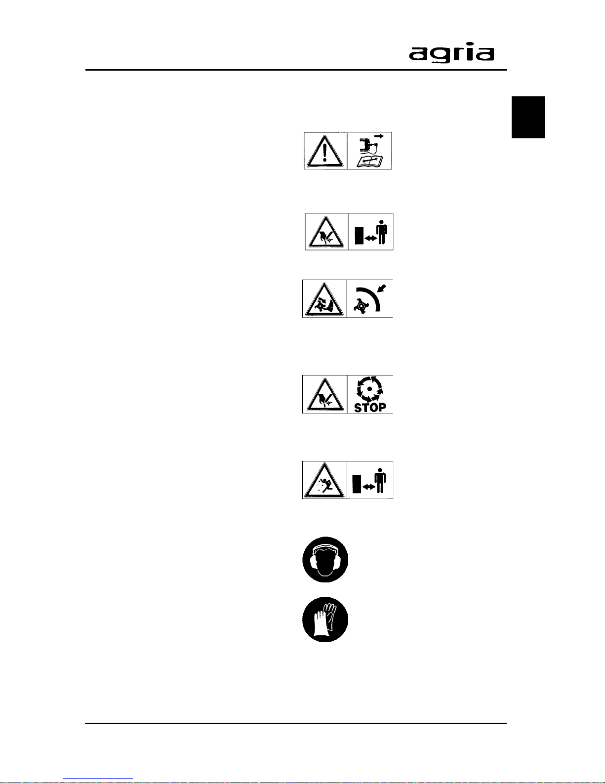
Explanation of
Warning Signs
Before any cleaning,
maintenance, and repair work switch off
the engine and pull
spark plug connector.
With engine running,
keep at a safe distance from hoeing
tools.
Do not work without
protective covers
mounted. Before
starting the engine,
bring covers into
proper position.
Do not touch any
moving machinery
parts. Wait until they
have come to acomplete stop.
With the engine
running, keep at a
safe distance.
Signs
When working with the
machine, wear individual
protective ear plugs.
Wear protective gloves.
1
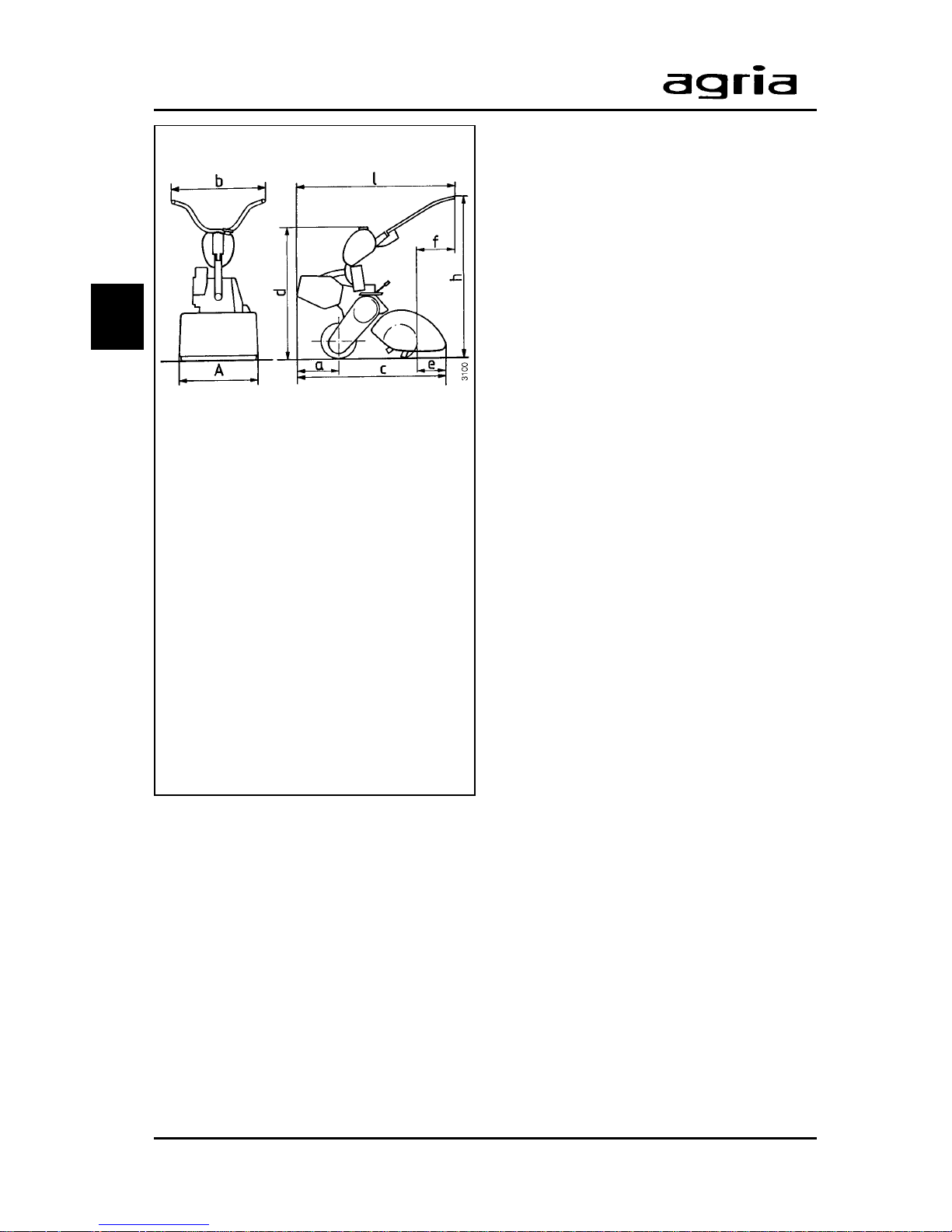
12 Single-wheel power hoe 2100
Machine Dimensions:
a ........................................ 310 mm
b ........................................ 620 mm
c....................................... 1000 mm
d ........................................ 890 mm
h ........................... ca.700–950 mm
l........................................ 1250 mm
A ................................ 100–650 mm
(depending on tilling attachment)
Safety requirements in accordance
with CEN/GS are met:
e ..................................... > 150 mm
f ..............> 500 mm at h = 800 mm
2. Specifications
T ype:........................................... 2100
T yre:.........................3.00-4 (field tyre)
T yre air pressure:................... 0.8 bar
Clutch:.................... Multi-plate clutch,
running in oil bath
Weight: ..........................approx. 47 kg
Gearbox:3-speed mechanical gearbox
with 1 roller chain to wheel shaft
Oil filling quantity:
Mechanical gearbox
in motor unit ............................... 0.30 l
in wheel drive............................. 0.15 l
in hoeing drive ........................... 0.30 l
Transmission oil BP TFJD - GL4 each
Travelling speeds:
1st gear ................................. 1.2 km/h
2nd gear................................ 2.6 km/h
3rd gear ................................ 4.5 km/h
Tilling shaft speed: .............. 293 rpm
at engine speed 4500 rpm
Tilling work width: .............10–65 cm
depending on tilling attachment
version = accessory
Accessories:
Tilling attachment 10–65 cm
Ridging attachment.............. 2152 011
Front weight ......................... 2128 011
Leaf deflector ....................... 2130 031
Noise levels:
Noise level
at operator’s ear LP: ................ 90 dBA
Sound lev el LW: .................. 101.5 dBA
(in accordance with EN 709)
Vibration acceleration value:
on handlebar:.............. a
hw
= 2,7 m/s
2
in accordance with EN 709, EN 1033
at 85% of rated engine speed with tool
at work.
2

Single-wheel power hoe 2100 13
2. Specifications
Engine
Manufacturer: ............................ agria
Type: ................................... 66/3 or 2*
Version: ....................... Fan-air-cooled
1-cylinder-2-stroke engine (petrol)
Engine lubrication: Petroil lubrication;
stoichiometric ratio 1:30
Bore: ........................................ 56 mm
Stroke:..................................... 58 mm
Cubic capacity: ....................150 ccm
Compression:.............................. 6 :1
Output: .................................... 4.8 kW
at 4500 rpm
Spark plug: .................... Bosch M10A
Spark plug gap ...............0.5…0.6 mm
Ignition system: .................. Flywheel
magnet ignition
Contact clearance....... 0.35…0.45 mm
Ignition point ............. 2.5 before u.d.c.
radio remote screened according to
VDE 0879
Starter: ..........................Recoil starter
Stop device:................. Contact break
via short circuit cable
Engine-stop-switch on handlebar
Fuel tank capacity: ....... approx. 4.5 l
Fuel:................................. Commercial
petrol/oil mixture 1:30
octane number min. 90 RON
and self-mixing
supergrade 2-stroke engine oil, e.g.
Shell: Super T, Super TX;
Esso: Exxon Special 2T Engine oil;
BP: 2T Special
(refer to fuel recommendations)
Air filter: ....................Oil bath air filter
Engine oil filling
quantity: ........................approx. 150ml
Carburetor: .... Piston slide carburetor
Bing 1/18/31 or 1/18/106
Air control screw: ..... in basic setting
approx. 1/2…1 1/2 revs. open
Main jet: ......................................... 95
Idle jet: ........................................... 45
Needle jet:.................................. 1108
Needle setting: ................................ II
Rated speed: ...................... 4800 rpm
Top no-load speed: ............6300 rpm
Idling speed:....................... 1800 rpm
Operability on Slopes:
Engine is suited for use on slopes:
continuous operation possible
up to ................. 45° inclination (100%)
2

14 Single-wheel power hoe 2100
The single-wheel power hoe agria 2100
is suited for common applications in
farming and forestry, horticulture and
park maintenance
The following attachments are a vailable:
Tilling attachment 10–65 cm
Ridging attachment
Front weight
Leaf deflector
Draft hoe
Engine
The two-stroke-petrol engine runs on
commercial petrol/oil mixture of a stoichiometric ratio 1:30.
For the first tank filling use a ratio of
1:25.
I
Note! Only use self-mixing spe-
cial 2-stroke engine oil (see
“Specifications”).
Also, ref er to fuel recommendations, p4.
During the first 20 operating hours
(break-in period) do not use engine to
maximum power. Even after break-in
period nev er use engine at higher speed
than necessary for the work in hand.
I
High engine speed is harm-
ful to any engine and considerably affects its durability. This applies especially for no load operation.
Any overspeed (have the engine r oar)
can result in immediate damage.
Cooling System
Cooling system is fan-cooled. Therefore
keep screen at recoil starter and cooling ribs of cylinder clean and free from
sucked-in plant trash.
Idling speed
Always ensure that idling-speed is adjusted correcty. At low speeds and with
the speed control lever set to idle, the
engine is supposed to run smoothly and
without run-out.
Air Filter
The air filter purifies the air intake. A
clogged filter reduces engine output.
Ignition System
The engine is equipped with a maintenance-free, contactless electronic ignition system. We recommend to have
necessary check-ups done by an expert
only.
3. Devices and Operating Elements
3
Single-wheel power hoe 2100 15
Speed Control Lever
The speed control lever (C/7) on the
steering handle is for stepless setting of
engine speed from min. = idle to max. =
full throttle.
Engine-off-switch
The single-wheel power hoe is equipped
with an electric off-switch (C/3). On
pressing the switch, the ignition is turned
off (engine is switched off).
Position "I" = Operation
Position "0" = Engine off
I
The engine-off-switch also
serves as emengency-off-
switch. Set the switch to “0” for fast
switch-off.
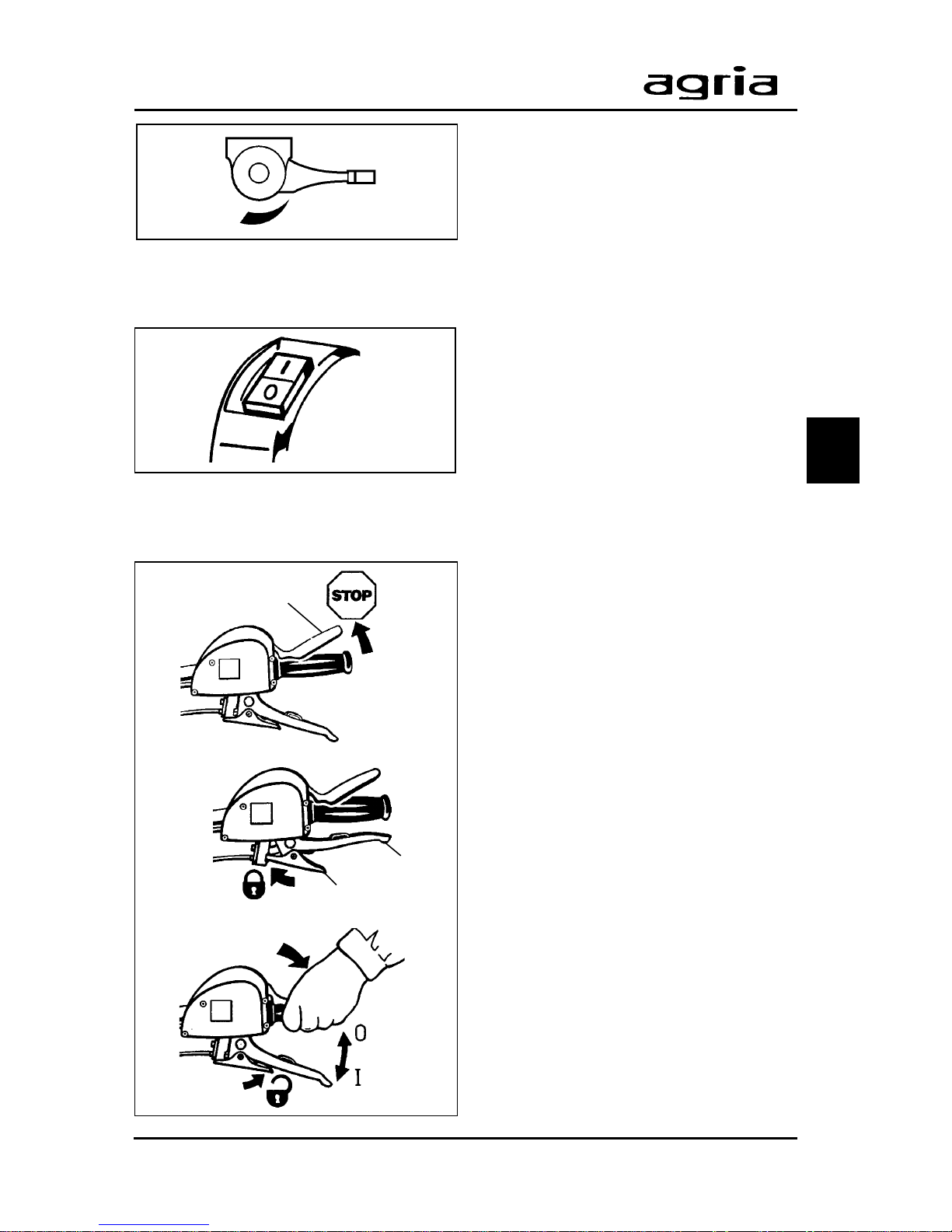
Safety Circuit
The single-wheel power hoe is equipped
with a safety switch (lever C/4). When
releasing the lever, the ignition system
is turned off (engine is off).
Stop position: When releasing the
lever, the ignition system is s witched off
(engine is off). Beware – engine keeps
running due to centrifugal mass.
Star t position: For starting the engine and for short breaks, pull the hand
clutch lever (C/5) and fasten with pawl
(C/6).
Operating position: To operate the
machine press safety lever (C/4).
W
Do not fasten safety lever.
I
The safety lever also serves to
switch off in an emergency.
Release the safety lever for fast engine
switch-off . The lev er automatically goes
to STOP position.
3. Devices and Operating Elements
3
max
min
C/4
C/5
C/6
 Loading...