

Page 1
Page 2

Table of Contents
Precautions...................................................................................................................................................3
About this manual 3
Important Operating Instructions 4
Getting Started ............................................................................................................................................5
Quick Setup 5
Unpacking 6
Attaching the Base 7
Adjusting the Monitor’s Tilting Angle 8
Security Slot 8
Making Connections 9
Removing the Rear-connector Cover 9
Connectors Close up 10
Replacing the Rear-connector Cover 11
Customizing your Monitor ...................................................................................................................... 12
Volume Adjust 12
Adjusting the Monitor’s Display 12
Selecting OSD Features 12
OSD Menus 14
Troubleshooting ........................................................................................................................................18
Troubleshooting Procedures 18
Warning Messages 18
Troubleshooting 19
LCD Panel Display Technical Features and Specifications 20
Regulations................................................................................................................................................. 21
FCC compliance 21
TCO’99 22
2
Page 3

P
RECAUTIONS
About this manual
This manual is designed to assist you in setting up and using the LCD monitor. Information
in this document has been carefully checked for accuracy; however, no guarantee is given to
the correctness of the contents. The information in this document is subject to change without notice. This document contains proprietary information protected by copyright. All
rights are reserved. No part of this manual may be reproduced by any mechanical, electronic
or other means, in any form, without prior written permission of the manufacturer.
3
Page 4

Important Operating Instructions
1. Please read the following instructions carefully. This manual should be retained for
future use.
2. To clean the LCD monitor screen, first, make sure the monitor is in the power off
mode. Unplug the monitor from its power source before cleaning it. Do not spray
liquid cleaners directly onto the unit. Without applying excessive pressure, clean
the screen with a slightly dampened rag.
3. Do not cover or obstruct the ventilation openings on the rear of the monitor.
4. Do not place your LCD monitor near a heat source or open window, or in a location
exposed to direct sunlight, dust, or mechanical vibration.
5. Do not place anything on top of the monitor-to-PC signal cord. Make sure the cord is
placed in an area where it will not be stepped on.
6. Do not apply pressure to the LCD screen. Excessive pressure may cause permanent
damage to the display.
7. Do not remove the cover or attempt to service this unit by yourself. You may void
the warranty.
8. Safe storage of the LCD monitor is in a range of minus 20 to plus 60 degrees Celsius.
9. Unplug the monitor if not in use for an extended period.
10. Use the original carton and packing materials when transporting the monitor.
11. Immediately unplug your monitor and call an authorized technician when:
The power or monitor-to-PC signal cord is frayed or damaged.
Liquid has been spilled into the monitor, or it has been exposed to rain.
The monitor has been dropped or the case has been damaged.
A distinct change in performance is noticed.
4
Page 5

G
ETTING STARTED
Your LCD monitor is versatile, ergonomic, and above all easy to use. The LCD monitor is capable of displaying most standards, from 640 x 480 VGA to 1280 by 1024 SXGA. Built-in stereo speakers provide excellent stereo sound while saving desktop space. Finally, the frontpanel controls allow you to easily adjust the monitor’s display parameters to suit your habits.
Quick Setup
Follow these directions to correctly set up your monitor.
1. Remove all packing materials and wrapping from the monitor (page 6).
2. Attach the base (page 7).
3. Place the monitor in its desired location. Ensure that there is space around the
monitor, especially the rear area near the vents.
4. Connect your video source and AC adapter (page 9).
5. Turn on the video source.
6. Press the power button on the monitor. The display should appear. If no display appears, check Warning Messages and Troubleshooting (page 18).
7. Ensure that your computer display is set at 1280X1024 pixels and 60Hz. Press the
AUTO button
. The monitor optimizes the display automatically.
Note! The monitor is compliant with VESA FPMPMI standards and can be wall- or armmounted. Before wall-mounting or arm-mounting, disassemble the monitor stand.
5
Page 6
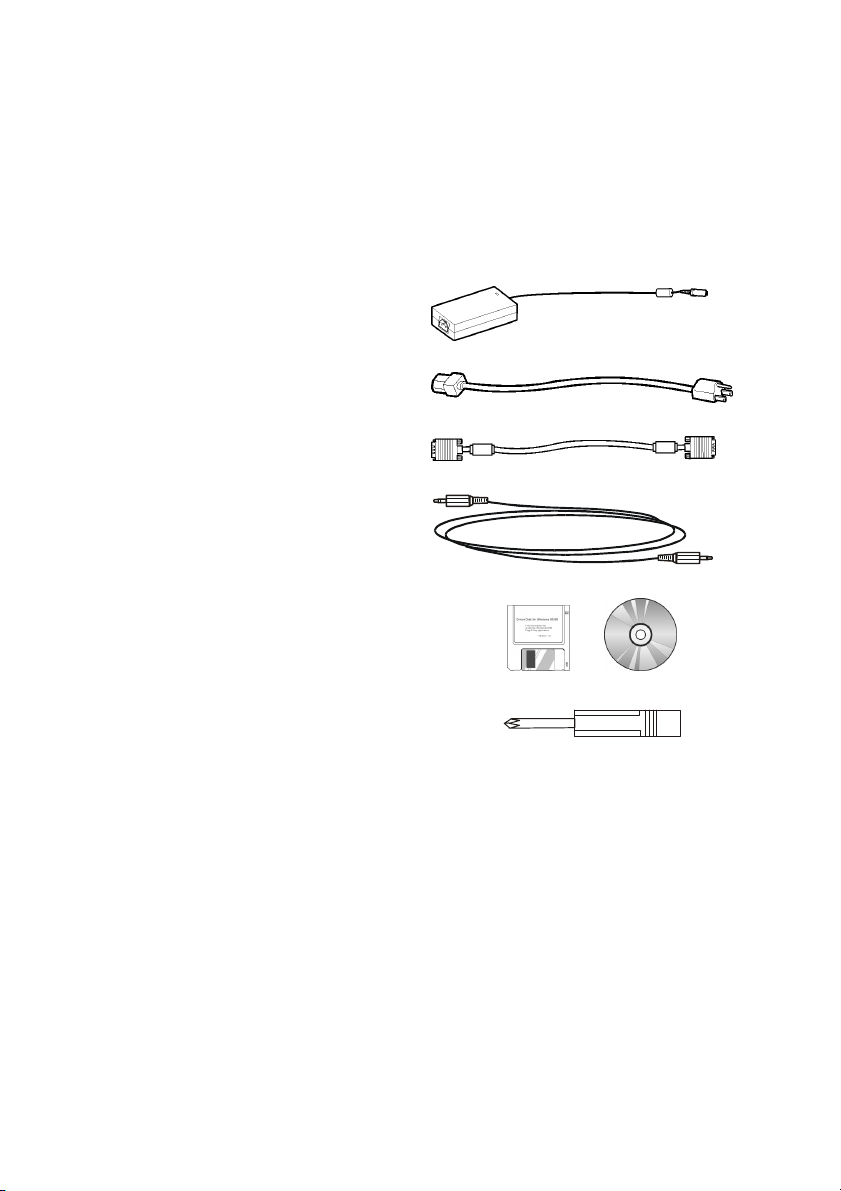
Unpacking
After you unpack the monitor, make sure the following items are included in the box and
are in good condition:
• LCD monitor 17-inch monitor without base
• Base assembly Includes base and screws
• Power adapter
• Power cord
• D-sub 15-pin VGA cable
• Audio cable
• Floppy/CD-ROM (containing
Windows information file and user’s
manual)
• Phillips screwdriver
If you find that any of these items are missing or appear damaged, contact your dealer immediately. Do not throw away the packing material or shipping carton in case you need to
ship or store the LCD monitor in the future.
6
Page 7
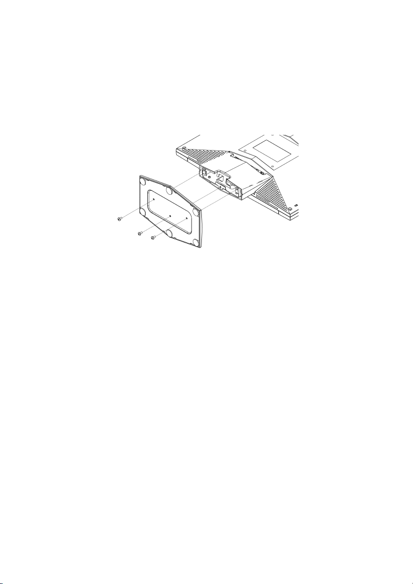
Attaching the Base
Before using the monitor, you must attach the base. You will need a Phillips screwdriver and
a blanket or foam sheet to lay the monitor on. The procedure is described below.
1. Cover a table with foam or a soft blanket to protect the monitor screen. Carefully
place the monitor with the screen facing down on the table.
2. Attach the base with the three screws.
3. Stand the monitor upright.
7
Page 8

Adjusting the Monitor’s Tilting Angle
Your LCD monitor’s vertical tilting angle can be adjusted between 0º ~ 20º for comfortable
viewing.
To adjust the tilting angle, grasp the
top corners of the monitor with both
hands and tilt to the desired angle.
Warning! Forcing the monitor past its maximum extension can result in damage to the
monitor.
0
20
Security Slot
Your LCD monitor has a security slot built in to the rear of the monitor.
If you have any doubts on the
security of your LCD monitor,
secure it to a permanent
object in the room by means of
the security slot shown here:
K
Note! Consult your local dealer for information on purchasing a security slot cable.
8
Page 9

Making Connections
Removing the Rear-connector Cover
Before making connections, you must remove the rear-connector cover. Refer to the following:
1. Tilt the monitor to its 0º vertical position. (See Adjusting the Monitor’s Tilting Angle
on page 8.)
2. Remove the cover by gripping at the top and pulling in the direction of the arrow as
shown here:
9
Page 10

Connectors Close up
The following illustration shows the connectors on the rear of the monitor. (Unplug the
power source when making connections. The final step in the following procedures should
be connecting the power adapter to a wall socket.)
1
Connector Cable Procedure
1 DC power
jack
2 Audio-in
jack
3 Audio-out
jack
4 VGA
port
Power cord and
adapter
Audio cable To avail of the monitor’s built-in stereo speakers,
Headphone cable (not
included)
D-sub 15-pin VGA cable Connect one end of the cable to the VGA port.
2
3
Plug the adapter power connector into this DC
power jack. Plug the female end of the power
cable into the AC-adapter and the male end of
the power cord into a wall socket.
plug the audio cable into this jack. Attach the
other end to your audio source.
You can attach your headphones to this jack.
Connect the other end to the PC’s VGA port.
Tighten the securing screws on both connectors.
4
10
Page 11

Replacing the Rear-connector Cover
After making connections, replace the rear-connector cover as shown below:
1. Loop the cables through the bracket as shown here:
2. Replace the cover at the bottom first; then push at the top until it “clicks” into place
as shown here:
11
Page 12

C
USTOMIZING YOUR MONITOR
This section covers the LCD monitor’s On-Screen Display (OSD), and front panel control buttons.
Important! Though manual adjustment of the LCD panel is available, we strongly recommend you to use the auto adjustment function of the panel. It will automatically
tune your LCD panel to the optimal performance. Simply push the AUTO button to enable the auto adjustment function. Additionally, we recommend you to use the auto
adjustment function every time after you have change the resolution or frequency of
your display.
Volume Adjust
Use the INCREASE + and DECREASE — buttons to quickly adjust the volume of the moni-
tor’s built-in stereo speakers.
Adjusting the Monitor’s Display
The LCD monitor features an intuitive, menu-driven, OSD. You can access the OSD any time
that the PC is powered up. If the PC is in a power saving mode, or is powered down, the OSD
is inaccessible.
Selecting OSD Features
1. Push or button to call out the OSD menu. The sixteen OSD icons are
represented in the following menu.
2. Push
3. Then push
4. In case of above Sub-function selection, push
selection.
or to move the highlight bar to the desired icon.
+ or — for adjustment or Sub-function selection.
or to confirm the desired
12
Page 13

5. In case of no OSD menu, the Icon
can do auto adjustment function.
6. In case of having OSD menu, the Icon
can do exit function.
13
Page 14

OSD Menus
Brightness Adjustment
Contrast Adjustment
Horizontal Position Adjustment
Vertical Position Adjustment
14
Page 15

Sharpness Adjustment
OSD Transparency Adjustment
Phase Adjustment
Clock Adjustment
15
Page 16

Color Temperature Selection
P.S. The color temperature of RGB can be adjusted in case of entering
“ USER ”sub menu.
Horizontal OSD Position Adjustment
Vertical OSD Position Adjustment
Graphic/Text Selection
P.S. Suggest the user select“ Text ”sub menu in case of the resolution being
640×350 or 640×400.
16
Page 17

Recall Selection
P.S. Suggest the user to use“ Recall ”icon, if the user doesn’t satisfy with the
adjustment.
Language Selection
Auto adjustment Selection
Exit Selection
17
Page 18

T
T
t
ROUBLESHOOTING
Troubleshooting Procedures
This LCD monitor comes pre-adjusted with standard VGA timing. Due to output timing differences among various VGA cards, you may initially experience an unstable or unclear display when a new display mode or new VGA card is selected.
Before applying any of the following troubleshooting procedures, you should first press the
AUTO
button to run the optimal adjustment option in the OSD menu.
Warning Messages
Message Solution
CAN NOT DISPLAY THIS INPUT
SIGNAL
NO SIGNAL INPUT No signal inputs are detected from either VGA-In .
MAIN CONTROL MENU LOCKED
/UNLOCKED
ADJUSTING FREQUENCY
ADJUSTING PHASE
ADJUSTING POSITION
The input signal is not acceptable by the monitor.
• Ensure that the video resolution and frequency range
are within that specified for the monitor. (Refer to the
“Technical Specifications” section of this user’s manual for details.)
• Check that the power switch of your computer or
video source is in the “ON” position.
• Check that the video signal cable is properly connected.
• Ensure that no pins are bent or pushed in the videoinput connector.
he main control menu (On-Screen Display menu) is locked
o avoid unwanted adjustment.
• Press
unlock the main control menu.
The monitor is detecting the input signal and automatically
adjusting the monitor parameters accordingly.
It takes around 5 seconds to finish the whole process.
• You are recommended to auto adjust by pressing the
refresh rate.
, , buttons together for 5 seconds to
button every time you change the resolution or
18
Page 19

Troubleshooting
Symptom Check Items
• No picture
• LED power indicator is
not lit
• No picture
• The LED power indicator
is orange
Text is not solid • Ensure that the resolution of the video signal is 1280
• Screen image is not
centered properly
• Some lines are missing
There are tiny red, green, blue
or black dots on the screen.
• Check that the monitor power switch is turned on.
• Check that the power adapter is properly connected to
the monitor.
• Check that the power cord is properly connected to
the power adapter.
• Check that the power cord is properly connected to
the power outlet.
• Check if there is electrical power coming from the
power outlet. Use another device to check for power.
• Ensure the computer is not in power saving mode.
(Move the mouse or press a key on the keyboard to
wake up the computer.)
• Check that your computer is in the “ON” position.
by 1024.
• Press the
• Adjust Clock and Phase in the OSD menu to fine-tune.
(Refer to the “Customizing Your Monitor” section of
this user’s manual for details.)
• Adjust Sharpness in the OSD menu if you are not in
1280 by 1024 resolution. (Please refer to the “Customizing Your Monitor” section of this user’s manual for
details.)
• Press the
• Adjust H. Position and V. Position to fine-tune. (Refer
to the “Customizing Your Monitor” section of this
user’s manual for details.)
The TFT LCD panel consists of millions of small transistors.
Defective transistors will each cause a missing red, green, or
blue dot.
button to run automatic adjustment.
button to run automatic adjustment.
19
Page 20

LCD Panel Display Technical Features and Specifications
Panel
Input Signal
Compatibility
Connector Power 3-Pin AC Plug
Audio
Tilt Tilt Angle 0º - 20º
Weight Net 4.8 Kg (10.6 lb)
Power
Panel Size 17 in. (432 mm)
Pixel Format 1280 by 1024 vertical strip
Frequency
Max. Pixel Clock 135 MHz
PC Max to 1280 by 1024 @ 75 Hz
Mac Max to 1280 by 1024 @ 75 Hz
Audio-In 3.5 mm audio line-in
Audio-Out 3.5 mm headphone jack
Speakers Two 2-watt built-in speakers
Amplifier 1.5W at 1 kHz
AC 100 ~ 245V, 47 ~ 63 Hz
Consumption
Horizontal: 30 kHz – 80 kHz,
Vertical: 50 Hz – 75 Hz
< 48 W (On),
< 5 W (Stand-by)
< 5 W (Off)
20
Page 21

R
EGULATIONS
FCC compliance
This device complies with Part 15 of the FCC Rules. Operation is subject to the following two
conditions: (1) this device may not cause harmful interference, and (2) this device must accept any interference received, including interference that may cause undesired operation.
NOTE: This equipment has been tested and found to comply with the limits for a Class B
digital device, pursuant to Part 15 of the FCC Rules. These limits are designed to provide reasonable protection against harmful interference in a residential installation. This equipment generates, uses and can radiate radio frequency energy and, if not installed and used
in accordance with the instructions, may cause harmful interference to radio communications. However, there is no guarantee that interference will not occur in a particular installation. If this equipment does cause harmful interference to radio or television reception,
which can be determined by turning the equipment off and on, the user is encouraged to
try to correct the interference by one or more of the following measures:
Reorient or relocate the receiving antenna.
Increase the separation between the equipment and receiver.
Connect the equipment to an outlet on a circuit different from that to which
the receiver is connected.
Consult the dealer or an experienced radio/TV technician for help.
WARNING: Any unauthorized modification to this equipment could result in the revocation of the authorization to operate the equipment and void the product warranty.
21
Page 22

TCO’99
Congratulations!
You have just purchased a TCO'99 approved and labelled product! Your choice has provided you with a
product developed for professional use. Your purchase has also contributed to reducing the burden on the
environment and also to the further development of environmentally adapted electronics products.
Why do we have environmentally labelled computers?
In many countries, environmental labelling has become an established method for encouraging the adaptation of goods and services to the environment. The main problem, as far as computers and other electronics equipment are concerned, is that environmentally harmful substances are used both in the
products and during their manufacture. Since it is not so far possible to satisfactorily recycle the majority
of electronics equipment, most of these potentially damaging substances sooner or later enter nature.
There are also other characteristics of a computer, such as energy consumption levels, that are important
from the viewpoints of both the work (internal) and natural (external) environments. Since all methods of
electricity generation have a negative effect on the environment (e.g. acidic and climate-influencing emissions, radioactive waste), it is vital to save energy. Electronics equipment in offices is often left running
continuously and thereby consumes a lot of energy.
What does labelling involve?
This product meets the requirements for the TCO'99 scheme which provides for international and environmental labelling of personal computers. The labelling scheme was developed as a joint effort by the
TCO (The Swedish Confederation of Professional Employees), Svenska Naturskyddsforeningen (The Swedish Society for Nature Conservation) and Statens Energimyndighet (The Swedish National Energy Administration).
Approval requirements cover a wide range of issues: environment, ergonomics, usability, emission of electric and magnetic fields, energy consumption and electrical and fire safety.
The environmental demands impose restrictions on the presence and use of heavy metals, brominated
and chlorinated flame retardants, CFCs (freons) and chlorinated solvents, among other things. The product
must be prepared for recycling and the manufacturer is obliged to have an environmental policy which
must be adhered to in each country where the company implements its operational policy.
The energy requirements include a demand that the computer and/or display, after a certain period of
inactivity, shall reduce its power consumption to a lower level in one or more stages. The length of time to
reactivate the computer shall be reasonable for the user.
Labelled products must meet strict environmental demands, for example, in respect of the reduction of
electric and magnetic fields, physical and visual ergonomics and good usability.
Below you will find a brief summary of the environmental requirements met by this product. The complete environmental criteria document may be ordered from:
TCO Development
SE-114 94 Stockholm, Sweden
Fax: +46 8 782 92 07
Email (Internet): development@tco.se
Current information regarding TCO'99 approved and labelled products may also be obtained via the
Internet, using the address: http://www.tco-info.com/
Environmental requirements
Flame retardants
Flame retardants are present in printed circuit boards, cables, wires, casings and housings. Their purpose
is to prevent, or at least to delay the spread of fire. Up to 30% of the plastic in a computer casing can con-
22
Page 23

sist of flame retardant substances. Most flame retardants contain bromine or chloride, and those flame
retardants are chemically related to another group of environmental toxins, PCBs. Both the flame retardants containing bromine or chloride and the PCBs are suspected of giving rise to severe health effects,
including reproductive damage in fish-eating birds and mammals, due to the bio-accumulative* processes.
Flame retardants have been found in human blood and researchers fear that disturbances in foetus development may occur.
The relevant TCO'99 demand requires that plastic components weighing more than 25 grams must not
contain flame retardants with organically bound bromine or chlorine. Flame retardants are allowed in the
printed circuit boards since no substitutes are available.
Cadmium**
Cadmium is present in rechargeable batteries and in the colour-generating layers of certain computer
displays. Cadmium damages the nervous system and is toxic in high doses. The relevant TCO'99 requirement states that batteries, the colour-generating layers of display screens and the electrical or electronics
components must not contain any cadmium.
Mercury**
Mercury is sometimes found in batteries, relays and switches. It damages the nervous system and is toxic
in high doses. The relevant TCO'99 requirement states that batteries may not contain any mercury. It also
demands that mercury is not present in any of the electrical or electronics components associated with
the labelled unit.
CFCs (freons)
The relevant TCO'99 requirement states that neither CFCs nor HCFCs may be used during the manufacture
and assembly of the product. CFCs (freons) are sometimes used for washing printed circuit boards. CFCs
break down ozone and thereby damage the ozone layer in the stratosphere, causing increased reception
on earth of ultraviolet light with e.g. increased risks of skin cancer (malignant melanoma) as a consequence.
Lead**
Lead can be found in picture tubes, display screens, solders and capacitors. Lead damages the nervous
system and in higher doses, causes lead poisoning. The relevant TCO´99 requirement permits the inclusion of lead since no replacement has yet been developed.
* Bio-accumulative is defined as substances which accumulate within living organisms
** Lead, Cadmium and Mercury are heavy metals which are Bio-accumulative.
23
 Loading...