

Page 1
Page 2

TABLE OF CONTENT
Precautions 2
INSTALLATION ...............................................................................................................................................2
POWER CONNECTION....................................................................................................................................2
USING THE TILT.............................................................................................................................................2
MAINTENANCE..............................................................................................................................................3
TRANSPORTING THE MONITOR......................................................................................................................3
Getting Started 4
PACKAGE CONTENTS .................................................................................................................................... 4
IDENTIFYING PARTS AND CONTROLS ..............................................................................................................5
SETUP ..........................................................................................................................................................6
Customizing your Monitor 7
WORKING WITH OSD GROUPS.....................................................................................................................7
DISPLAY ADJUST .......................................................................................................................................... 8
Color Temperature.................................................................................................................................8
OSD Adjust................................................................................................................................................8
Misc Adjust...............................................................................................................................................8
Brightness & Contrast .......................................................................................................... .................9
Horizontal & Vertical Position............................................................................................................9
Clock & Phase...........................................................................................................................................9
Auto Adjust...............................................................................................................................................9
White Balance........................................................................................................................................10
Selecting a Color Temperature setting..........................................................................................10
Selecting a User-Defined Color Balance Setting.........................................................................10
OSD Position...........................................................................................................................................10
OSD Time..................................................................................................................................................11
Transparency OSD................................................................................................................................. 11
Selecting a Language ........................................................................................................................... 11
Recall.......................................................................................................................................................... 11
Mode Text/Graphics.............................................................................................................................12
Information.............................................................................................................................................12
Backlight...................................................................................................................................................12
Sharpness.................................................................................................................................................12
Warning Messages and Troubleshooting 13
WARNING MESSAGES.................................................................................................................................13
TROUBLESHOOTING ....................................................................................................................................14
LCD PANEL DISPLAY TECHNICAL FEATURES AND SPECIFICATIONS...............................................................15
Regulations 16
FCC COMPLIANCE.......................................................................................................................................16
TCO'95...................................................................................................................................................... 17
TCO’99......................................................................................................................................................19
1
Page 3

Precautions
Installation
l Do not cover or block the ventilation ports on the rear of the monitor.
l Do not install the monitor close to heat sources such as radiators or air ducts, or in
a location exposed to direct sunlight, excessive dust, mechanical vibration, or
shock.
Power connection
l Use the correct power cord for your local voltage.
l Use an accessible outlet close to the monitor.
l Do not allow anything to rest on the power cable.
l Disconnect the power cable from the power supply if:
Ø You will not use the monitor for an extended period.
Ø The cable is damaged or frayed.
Ø The monitor has been dropped or the cabinet damaged.
Ø A distinct change in performance indicates a need for servicing.
Using the Tilt
l Use the monitor’s tilt capability to adjust its vertical orientation to an appropriate
position. Grasp the top corners of the monitor with both hands and tilt to the
desired angle.
For use only with power supply Lien,LE-9702B and Chi Sam , CH-1024
2
Page 4

Maintenance
l Clean the cabinet and controls with a soft cloth lightly moistened with a mild
detergent solution. Do not use any abrasive materials or solvents such as alcohol
or benzene.
l Do not rub, touch, or tap the surface of the screen with sharp or abrasive items
such as pens or screwdrivers, as the screen may scratch.
l Do not insert objects or spill liqui d s int o the ventilation p orts on the monitor’s rear,
as fire, electric shock, and/or unit failure may result.
Transporting the monitor
When transporting the monitor for repair or shipment, use the original carton and
packing materials.
3
Page 5
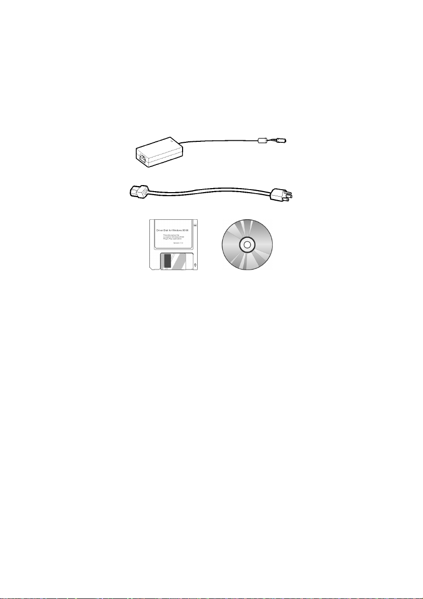
Package contents
Before beginning, ensure that the carton contains the following items:
l Monitor
l Power adapter
l Power cord
l Floppy/CD-ROM containing Windows
l This manual
®
information file
Getting Started
4
Page 6
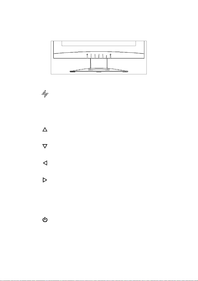
Identifying parts and controls
The center front panel of the monitor carries the control array.
The controls are, from left to right:
AUTO button
Automatically adjusts the picture and performance. The AUTO
function should be used the first time you use the monitor and
after changing the resolution and/or refresh rate of the input
signal. The AUTO button also closes the OSD.
DOWN button
Activates the OSD and navigates within the display
UP button
Activates the OSD and navigates within the display
LEFT button
Activates the OSD and navigates within the display
RIGHT button
Activates the OSD and navigates within the display
LED indicator
Indicates the monitor’s operational mode; green for regular
operation, and amber for power saving mode.
FRONT VIEW
Power Switch
Turns the monitor on and off
5
Page 7

Setup
Follow these directions to correctly set up your monitor.
1. Remove all packing materials and wrapping from the monitor
2. Place the monitor in its desired location. Ensure that there is space around the
monitor, especially the rear area.
3. With the computer turned off, connect the VGA signal cable. The native
monitor cable connects to the 15-pin compatible VGA port on your IBM/PC
computer.
4. With the monitor switched off, connect the monitor end power plug of
adaptor to the power jack adjacent to the VGA cable on the underside of the
monitor.
5. Connect the power cord to the adapter and the power plug to the power
source.
6. Turn on the computer.
7. Press the power switch on the monitor. The display should appear. If no
display appears, check Warning Messages and Troubleshooting in this manual.
8. Ensure that your computer display is set at 1024X768 pixels and 60Hz. Press
the AUTO button
Note: The monitor is compliant with VESA FP MPMI standards and can be wall- or arm-
mounted. Before wall-mounting or arm-mounting, please disassemble the
monitor stand first.
. The monitor optimizes the display automatically.
6
Page 8

Customizing your Monitor
The On Screen Display (OSD) system provides a full range of customizable tools to
optimize your display.
Important: While full customization is available, we strongly recommend using the
AUTO settings, which are preset to fully optimize your monitor’s performance. Simply
press the AUTO button
execute the AUTO function following any change made to your display from your
computer.
Working with OSD Groups
1. Press any of the UP, DOWN, LEFT, or RIGHT buttons to open the OSD window.
OSD functions are divided into four Groups. Icons
representing these groups appear across the top of the
OSD display. From left to right, the OSD Groups are:
to engage the AUTO settings. It is also recommended that you
Display Adjust
Color Temperature
OSD Adjust
Misc Adjust (miscellaneous adjust)
2. To select an OSD Area, with the OSD window open, press the DOWN
buttons until the desired Area’s icon is highlighted and that Area’s
UP
setting items are listed.
3. Press the RIGHT
4. Use the DOWN
displayed menu.
5. With the setting selected, use the RIGHT
settings as listed under each setting in the following section.
6. Use the DOWN
7. Push the AUTO button
selection menu.
8. Push the AUTO button
or LEFT button once to enter the setting menu area.
or UP buttons to select the desired setting from the Area’s
or LEFT buttons to change the
or UP buttons to select a new menu item.
once to save settings and return to the Area
again to exit the OSD.
7
or
Page 9

The OSD Areas contain the following adjustment functions:
Display Adjust
Color Temperature
OSD Adjust
Misc Adjust
8
Page 10

Brightness & Contrast
1. To fine-tune the monitor’s brightness and contrast, select the pertinent item
from the menu.
2. Use the RIGHT
scale that appears at the bottom of the window.
3. Push the AUTO button
selection menu.
and LEFT buttons to set the display as desired on the 0-100
once to save settings and return to the Area
Horizontal & Vertical Position
1. To fine-tune the display’s position on the monitor screen, select the pertinent
item from the menu.
2. Use the RIGHT
scale that appears at the bottom of the window.
3. Push the AUTO button
selection menu.
and LEFT buttons to set the display as desired on the 0-100
once to save settings and return to the Area
Clock & Phase
1. To fine tune picture performance to compe nsate for drifts in the computer
signal, select the pertinent item from the menu.
2. Use the RIGHT
100 scale that appears at the bottom of the window.
3. Push the AUTO button
selection menu.
and LEFT buttons to set the display as desired on t he 0-
once to save settings and return to the Area
Auto Adjust
1. To enable the monitor’s Auto Adjust capability, select Auto Adjust from the
menu.
2. Use the RIGHT
desired at the bottom of the window.
3. Push the AUTO button
selection menu.
and LEFT buttons to toggle between YES and NO as
once to save settings and return to the Area
9
Page 11

White Balance
1. To enable the monitor’s automatic White Balance capability, select White
Balance from the menu.
2. Use the RIGHT
desired at the bottom of the window.
3. Push the AUTO button
selection menu.
and LEFT buttons to toggle between YES and NO as
once to save settings and return to the Area
Selecting a Color Temperature setting
The following conditions are recommended for the available settings:
Setting Use
9300K General Use
6500K Color Management
5500K Photo Retouching
1. Select the desired setting from the menu.
2. Push the AUTO button
selection menu.
once to save settings and return to the Area
Selecting a User-Defined Color Balance Setting
You can fine-tune the red/green/blue picture settings according to your preference or
specific application
1. Select the pertinent color category from the menu.
2. Use the RIGHT
100 scale.
and LEFT buttons to set the display as desired on t he 0-
OSD Position
3. Push the AUTO button
selection menu.
1. To position the OSD window to your preference, select OSD Position from the
menu.
2. Use the RIGHT
positions.
3. Push the AUTO button
selection menu.
and LEFT buttons to move the display through its available
once to save settings and return to the Area
once to save settings and return to the Area
10
Page 12

OSD Time
1. To set the duration of the OSD window’s display, select OSD Time from the
menu.
2. Use the RIGHT
30, 40, 50, 60 seconds.
3. Push the AUTO button
selection menu.
and LEFT buttons to set the time as desired on off, 10, 20,
once to save settings and return to the Area
Transparency OSD
1. To change the transparency of the OSD window, select Transparency OSD from
the menu.
2. Use the RIGHT
scale.
3. Push the AUTO button
selection menu.
and LEFT buttons to set the display as desired on the 0-100
once to save settings and return to the Area
Selecting a Language
1. To select the language in which you wish the OSD to appear, select Language
from the menu.
2. Use the RIGHT
languages shown at the bottom of the window.
3. Push the AUTO button
selection menu.
and LEFT buttons to toggle through the available
once to save settings and return to the Area
Recall
1. To retur n the monitor’s settings to the factory defa ult, select Recall from the
menu.
2. Use the RIGHT
desired at the bottom of the window.
and LEFT buttons to toggle between YES and NO as
3. Push the AUTO button once to save settings and return to the Area
selection menu.
11
Page 13

Mode Text/Graphics
1. To choose between the monitor’s automatic Sharpness opti mization for Text
or Graphic use, select Mode Text/Graphic from the menu.
2. Use the RIGHT
desired at the bottom of the window.
3. Push the AUTO button
selection menu.
Note: For better performance, please change to “Text” mode when display resolution
is set at 720 x 400 and change to “Graphics” m od e whe n display resolution is set
to 640 x 250.
and LEFT buttons to toggle between TEXT and GRAPHIC as
once to save settings and return to the Area
Information
Select Information from the menu to display 15" LCD Monitor.
Backlight
1. To set the brightness of the monitor’s backlight, select Backlight from the
menu.
2. Use the RIGHT
100 scale.
3. Push the AUTO button
selection menu.
and LEFT buttons to set the brightness as desired on the 1-
once to save settings and return to the Area
Sharpness
1. To set the sharpness of the display, select sharpness from the menu.
2. Use the RIGHT
Softer-Sharper scale.
3. Push the AUTO button
selection menu.
and LEFT buttons to set the sharpness as desired on the
once to save settings and return to the Area
12
Page 14

Warning Messages and Troubleshooting
Warning Messages
Message Solution
CAN NOT DISPLAY THIS
INPUT SIGNAL
NO SIGNAL INPUT No signal inputs are detected from either VGA-In or S-Video
MAIN CONTROL MENU
LOCKED
WAIT FOR AUTOMATIC
ADJUSTMENT
The input signal is not acceptable by the monitor.
· Please ensure that the video resolution and frequency range
are within that specified for the monitor.
· Please refer to the “Technical Specifications” section of this
user manual for details.
connector.
· Check that the power switch of your computer or video
source is in the “ON” position.
· Check that the video signal cable is properly connected.
· Ensure that no pins are bent or pushed in the video input
connector.
· The main control menu (On-Screen Display menu) is locked
to avoid unwanted adjustment. Hold RIGHT
buttons together for 5 seconds to unlock the main control
menu.
The monitor is detecting the input signal and automatically
adjusting the monitor parameters accordingly.
· It takes around 5 seconds to finish the whole process.
and LEFT
· You are recommended to auto adjust by pressing the
button every time you change the resolution or refresh rate.
13
Page 15

Troubleshooting
Symptom Check Items
· No picture
· LED power indicator is
not lit
· No picture
· The LED power
indicator is orange
· Text is not solid · Ensure that the resolution of the video signal is 1024 by 768.
· Screen image is not
centered properly
· Some lines are missing
· There are tiny red,
green, blue or black
dots on the screen.
· Check that the monitor power switch is turned on.
· Check that the power adapter is properly connected to the
monitor.
· Check that the power cord is properly connected to the power
adapter.
· Check that the power cord is properly connected to the power
outlet.
· Check there is electrical power coming from the power
outlet. Use another device to check for power.
· Ensure the computer is not in power saving mode. (Move the
mouse or press a key on the keyboard to wake up the
computer.)
· Check that your computer or video source power switch is in
the “ON” position.
· Check that the video signal cable is properly connected.
· Press the
· Adjust Clock and Phase in the OSD menu to fine tune. (Please
refer to the “Customizing Your Monitor” section of this user
manual for details.)
· Adjust Sharpness in the OSD menu if you are not in 1024 by
768 resolution. (Please refer to the “Customizing Your
Monitor” section of this user manual for details.)
· Press the
· Adjust H. Position and V. Position to fine tune. (Please refer to
the “Customizing Your Monitor” section of this user manual
for details.)
· The TFT LCD panel consists of millions of small transistors.
Defective transistors will each cause a missing red, green, or
blue dot.
button to run automatic adjustment.
button to run automatic adjustment.
14
Page 16

LCD Panel Display Technical Features and Specifications
Panel
Compatibility
Connector Power 3-Pin AC Plug
Tilt Tilt Angle 0º - 20º
Weight Net 3.2Kg (7.1 lb)
Power
Screen Size 15" (381mm) diagonal
Pixel Format 1024 x 768 vertical strip
Frequency
Max. Pixel Clock 80MHz
PC Max to 1024 x 768 @ 75Hz
Mac Max to 1024 x 768 @ 75Hz
AC 100 ~ 240V, 50 ~ 60Hz
Consumption
Horizontal: 30kHz - 60kHz,
Vertical: 50Hz - 75Hz Input Signal
< 48 Watts (On),
< 5 Watts (Stand-by),
< 5 Watts (Off)
15
Page 17

Regulations
FCC compliance
This device complies with Part 15 of the FCC Rules. Operation is subject to the following
two conditions: (1) this device may not cause harmful interference, and (2) this device
must accept any interference received, including interference that may cause undesired
operation.
NOTE: This equipment has been tested and found to comply with the limits for a Class B
digital device, pursuant to Part 15 of the FCC Rules. These limits are designed to provide
reasonable protection against harmful interference in a residential installation. This
equipment generates, uses and can radiate radio frequency energy and, if not installed
and used in accordance with the instructions, may cause harmful interference to radio
communications. However, there is no guarantee that interference will not occur in a
particular installation. If this equipment does cause harmful interference to radio or
television reception, which can be determined by turning the equipment off and on, the
user is encouraged to try to correct the interference by one or more of the following
measures:
Ø Reorient or relocate the receiving antenna.
Ø Increase the separation between the equipment and receiver.
Ø Connect the equipment to an outlet on a circuit different from that to which
the receiver is connected.
Ø Consult the dealer or an experienced radio/TV technician for help.
WARNING: Any unauthorized modification to this equipment could result in the
revocation of the authorization to operate the equipment and void the
product warranty.
16
Page 18

TCO'95
Congratulations!
You have just purchased a TCO'95 approved and labelled product! Your choice has provided you
with a product developed for professional use. Your purchase has also contributed to reducing the
burden on the environment and also to the further development of environmentally adapted
electronics products.
Why do we have environmentally labelled computers?
In many countries, environmental labelling has become an established method for encouraging the
adaptation of goods and services to the environment. The main problem, as far as computers and
other electronics equipment are concerned, is that environmentally harmful substances are used
both in the products and during the manufacturing. Since it has not been possible for the majority of
electronics equipment to be recycled in a satisfactory way, most of these potentially damaging
substances sooner or later enter nature.
There are also other characteristics of a computer, such as energy consumption levels, that are
important from the viewpoints of both the work (internal) and natural (external) environments. Since
all methods of conventional electricity generation have a negative effect on the environment (acidic
and climate-influencing emissions, radioactive waste, etc.), it is vital to conserve energy. Electronics
equipment in offices consume an enormous amount of energy since they are often left running
continuously.
What does labeling involve?
This product meets the requirements for the TCO'95 scheme that provides for international and
environmental labelling of personal computers. The labelling scheme was developed as a joint effort
by the TCO (The Swedish Confederation of Professional Employees), Naturskyddsforeningen (The
Swedish Society for Nature Conservation) and NUTEK (The National Board for Industrial and
Technical Development in Sweden).
The requirements cover a wide range of issues: environment, ergonomics, usability, emission of
electrical and magnetic fields, energy consumption and electrical and fire safety.
The environmental demands concern restrictions on the presence and use of heavy metals,
brominated and chlorinated flame-retardants, CFCs (freons) and chlorinated solvents, among other
things. The product must be prepared for recycling and the manufacturer is obliged to have an
environmental plan which must be adhered to in each country where the company implements its
operational policy.
The energy requirements include a demand that the computer and/or display, after a certain period of
inactivity, shall reduce its power consumption to a lower level in one or more stages. The length of
time to reactivate the computer shall be reasonable for the user.
Labelled products must meet strict environmental demands, for example, in respect of the reduction
of electric and magnetic fields, physical and visual ergonomics and good usability.
On the back page of this folder, you will find a brief summary of the environmental requirements met
by this product. The complete environmental criteria document may be ordered from:
TCO Development Unit
S-114 94 Stockholm, Sweden
Fax: +46 8 782 92 07
Email (Internet): development@tco.se
17
Page 19

Current information regarding TCO'95 approved and labelled products may also be obtained via the
Internet, using the address: http://www.tco-info.com/
TCO’95 is a co-operative project between TCO (The Swedish Confederation of Professional
Employees), Naturskyddsforeningen (The Swedish Society for Nature Conservation) and NUTEK
(The National Board for Industrial and Technical Development in Sweden).
Environmental requirements
Brominated flame retardants
Brominated flame retardants are present in printed circuit boards, cables, wires, casings and
housings. In turn, they delay the spread of fire. Up to thirty percent of the plastic in a computer casing
can consist of flame retardant substances. There are related to another group of environmental
toxins, PCBs which are suspected to give rise to similar harm, including reproductive damage in fish
eating birds and mammals, due to the bio-accumulative processes. Flame-retardants have been
found in human blood and researchers fear that disturbances in foetus development may occur.
TCO'95 demand requires that plastic components weighing more than 25 grams must not contain
organically bound chlorine and bromine.
Lead**
Lead can be found in picture tubes, display screens, solders and capacitors. Lead damages the
nervous system and in higher doses, causes lead poisoning. TCO’95 requirement permits the
inclusion of lead since no replacement has yet been developed.
Cadmium**
Cadmium is present in rechargeable batteries and in the colour-generating layers of certain computer
displays. Cadmium damages the nervous system and is toxic in high doses. TCO'95 requirement
states that batteries may not contain more than 25 ppm (parts per million) of cadmium. The colourgenerating layers of display screens must not contain any cadmium.
Mercury**1
Mercury is sometimes found in batteries, relays and switches. Mercury damages the nervous system
and is toxic in high doses. TCO'95 requirement states that batteries may not contain more than 25
ppm (parts per million) of mercury. It also demands that no mercury is present in any of the electrical
or electronics components concerned with the display unit.
CFCs (freons)
CFCs (freons) are sometimes used for washing printed circuit boards and in the manufacturing of
expanded foam for packaging. CFCs break down ozone and thereby damage the ozone layer in the
stratosphere, causing increased reception on earth of ultraviolet light with consequent increased risks
of skin cancer (malignant melanoma).
The relevant TCO'95 requirement: Neither CFCs nor HCFCs may be used during the manufacturing
of the product or its packaging.
*Bio-accumulative is defined as substances which accumulate within living organisms
**Lead, Cadmium and Mercury are heavy metals which are Bio-accumulative.
18
Page 20

TCO’99
Congratulations!
You have just purchased a TCO'99 approved and labelled product! Your choice has provided you
with a product developed for professional use. Your purchase has also contributed to reducing the
burden on the environment and also to the further development of environmentally adapted
electronics products.
Why do we have environmentally labelled computers?
In many countries, environmental labelling has become an established method for encouraging the
adaptation of goods and services to the environment. The main problem, as far as computers and
other electronics equipment are concerned, is that environmentally harmful substances are used
both in the products and during their manufacture. Since it is not so far possible to satisfactorily
recycle the majority of electronics equipment, most of these potentially damaging substances sooner
or later enter nature.
There are also other characteristics of a computer, such as energy consumption levels, that are
important from the viewpoints of both the work (internal) and natural (external) environments. Since
all methods of electricity generation have a negative effect on the environment (e.g. acidic and
climate-influencing emissions, radioactive waste), it is vital to save energy. Electronics equipment in
offices is often left running continuously and thereby consumes a lot of energy.
What does labelling involve?
This product meets the requirements for the TCO'99 scheme which provides for international and
environmental labelling of personal computers. The labelling scheme was developed as a joint effort
by the TCO (The Swedish Confederation of Professional Employees), Svenska
Naturskyddsforeningen (The Swedish Society for Nature Conservation) and Statens
Energimyndighet (The Swedish National Energy Administration).
Approval requirements cover a wide range of issues: environment, ergonomics, usability, emission of
electric and magnetic fields, energy consumption and electrical and fire safety.
The environmental demands impose restrictions on the presence and use of heavy metals,
brominated and chlorinated flame retardants, CFCs (freons) and chlorinated solvents, among other
things. The product must be prepared for recycling and the manufacturer is obliged to have an
environmental policy which must be adhered to in each country where the company implements its
operational policy.
The energy requirements include a demand that the computer and/or display, after a certain period of
inactivity, shall reduce its power consumption to a lower level in one or more stages. The length of
time to reactivate the computer shall be reasonable for the user.
Labelled products must meet strict environmental demands, for example, in respect of the reduction
of electric and magnetic fields, physical and visual ergonomics and good usability.
Below you will find a brief summary of the environmental requirements met by this product. The
complete environmental criteria document may be ordered from:
TCO Development
SE-114 94 Stockholm, Sweden
Fax: +46 8 782 92 07
Email (Internet): development@tco.se
19
Page 21

Current information regarding TCO'99 approved and labelled products may also be obtained via the
Internet, using the address: http://www.tco-info.com/
Environmental requirements
Flame retardants
Flame retardants are present in printed circuit boards, cables, wires, casings and housings. Their
purpose is to prevent, or at least to delay the spread of fire. Up to 30% of the plastic in a computer
casing can consist of flame retardant substances. Most flame retardants contain bromine or chloride,
and those flame retardants are chemically related to another group of environmental toxins, PCBs.
Both the flame retardants containing bromine or chloride and the PCBs are suspected of giving rise
to severe health effects, including reproductive damage in fish-eating birds and mammals, due to the
bio-accumulative* processes. Flame retardants have been found in human blood and researchers
fear that disturbances in foetus development may occur.
The relevant TCO'99 demand requires that plastic components weighing more than 25 grams must
not contain flame retardants with organically bound bromine or chlorine. Flame retardants are
allowed in the printed circuit boards since no substitutes are available.
Cadmium**
Cadmium is present in rechargeable batteries and in the colour-generating layers of certain computer
displays. Cadmium damages the nervous system and is toxic in high doses. The relevant TCO'99
requirement states that batteries, the colour-generating layers of display screens and the electrical or
electronics components must not contain any cadmium.
Mercury**
Mercury is sometimes found in batteries, relays and switches. It damages the nervous system and is
toxic in high doses. The relevant TCO'99 requirement states that batteries may not contain any
mercury. It also demands that mercury is not present in any of the electrical or electronics
components associated with the labelled unit.
CFCs (freons)
The relevant TCO'99 requirement states that neither CFCs nor HCFCs may be used during the
manufacture and assembly of the product. CFCs (freons) are sometimes used for washing printed
circuit boards. CFCs break down ozone and thereby damage the ozone layer in the stratosphere,
causing increased reception on earth of ultraviolet light with e.g. increased risks of skin cancer
(malignant melanoma) as a consequence.
Lead**
Lead can be found in picture tubes, display screens, solders and capacitors. Lead damages the
nervous system and in higher doses, causes lead poisoning. The relevant TCO´99 requirement
permits the inclusion of lead since no replacement has yet been developed.
* Bio-accumulative is defined as substances which accumulate within living organisms
** Lead, Cadmium and Mercury are heavy metals which are Bio-accumulative.
20
 Loading...