

Page 1

YIELD MONITOR 2000
Operators Manual
Manual written with assistance from:
Tri-Tech Communications & Publications, 1636 13th St., Boone, IA 50036
Page 2

Page 3

Yield Monitor 2000
Ag Leader Technology
General
Welcome
System Upgrades
Welcome to the Ag Leader Technology family. Ag Leader Technology is
dedicated to developing advanced, yet practical and cost-effective tools for
grain production. Above all, however, we are dedicated to meeting your
needs for support of existing products and development of product
improvements.
We want to hear from you! Feel free to call any time to discuss:
• Operational problems with your system
• Features you don’t like about your system
• Features you would like added to your system
We will do our best to ensure that you are happy with your current system
and that it is upgraded in the future to better meet your needs.
Ag Leader Technology will periodically mail to you a program chip that
replaces the existing chip in your monitor console. The new chip will
upgrade your monitor, make it easier to use, and may add new features.
To receive an upgrade chip and new product news, you must send in or
fax (515-232-3595) the Registration Form that is at the beginning of the
operator’s manual. Our mailing address is:
Limited Warranty
Ag Leader Technology
1203A Airport Road
P.O. Box 2348
Ames, IA 50010
Ag Leader Technology will repair or replace at no charge any component of
the Yield Monitor 2000 system that fails during normal service on the
combine model for which the system is intended to be used within two years
from the date of first use.
Warranty is not provided for damage resulting from abuse, neglect,
accidents, vandalism, acts of nature, or any other causes that are outside the
normal, intended use of the Yield Monitor 2000 system.
June 1997
1-1
Page 4

General
Yield Monitor 2000
Ag Leader Technology
Ag Leader Technology shall not be liable for indirect, incidental, or
consequential damages to the dealer, end user, or third parties arising from
the sale, installation, or use of the Yield Monitor 2000 system.
Service
Copyright Notice
If you have a problem with your system, call us directly at the phone number
below. If we determine you have a hardware failure, we will ship
replacement hardware immediately. Our mailing address and phone numbers
are:
Ag Leader Technology
1203A Airport Road
P.O. Box 2348
Ames, IA 50010
Phone: 515-232-5363
Fax: 515-232-3595
Note: Return failed hardware to us by UPS (preferred) or US mail..
Ag Leader Technology has copyrighted (1996) the contents of this manual
and the operating program for the Yield Monitor 2000 system. No
reproductions of this material may be made without first obtaining the
consent of Ag Leader Technology.
Proprietary
Technology Notice
1-2
The Yield Monitor 2000 system has patents on its design and operational
features. Copying features of this system relating to measurement and
calculation of grain flow and weight or organization of field and load data
may result in patent infringement.
* * *
June 1997
Page 5
Yield Monitor 2000
Ag Leader Technology
Setup Overview
Important Notices
Section Contents
The yield monitor must be set up before field operation, but before you begin
the setup procedures, read the following notices:
• You can upgrade the Yield Monitor 2000 console by replacing a
computer chip inside the box. To receive the free upgrade chip, you
must send in the registration form at the beginning of the operator’s
manual.
• If you plan to make yield maps on your own computer, you will need to
use Precision Map 2000 (or another mapping program that can process
memory cards from the Yield Monitor 2000) to process the memory
cards when they get full. You can also purchase memory cards from Ag
Leader Technology. Precision Map 2000 comes with your Yield
Monitor 2000 kit.
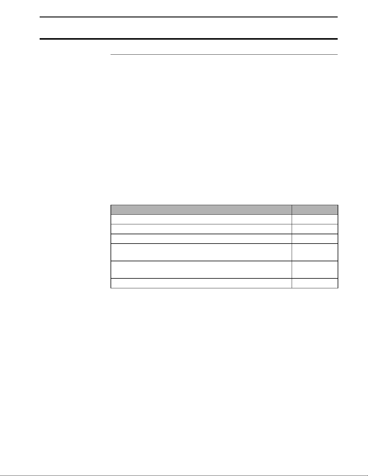
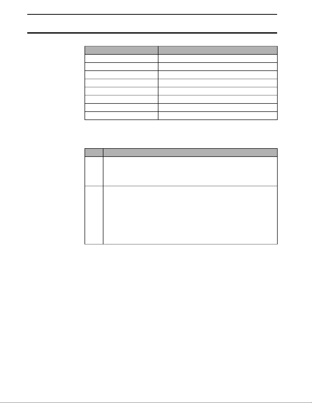
The following subjects are detailed in this section:
Subject Page
General Description 2-2
Before Setup 2-9
Setting Date and Time 2-10
Logging Settings 2-11
Settings Under SETUP Key 2-14
Setting Swath 2-17
Speed Setting 2-19
Setting Moisture 2-21
Setting Dry % Moisture, Dry Lbs/Bu 2-22
Setting Initial Calibration Numbers 2-23
Starting, Naming Fields/Loads 2-25
Setting Stop Height 2-31
Copying Memory to Backup 2-32
June 1997
* * *
2-1
Page 6

General Description
Yield Monitor 2000
Ag Leader Technology
Introduction
Monitor
Organization
The yield monitor is designed to accurately measure and record acres,
moisture, grain weight, bushels, and yield in bu/ac on-the-go. It is GPS
compatible and can log yield mapping data on memory cards. The yield
monitor must be calibrated to be accurate.
If you are using the monitor with a GPS receiver, you must use a
memory card to save GPS information. If you do not have a GPS
receiver, you do not need a memory card; the monitor has enough internal
memory for 976 total loads and 255 total fields which should last the entire
season.
The monitor is organized by fields and loads. A load subdivides a field into
smaller sections. A monitor load can be smaller or larger than a combine
tank, wagon, or truck load. It is recommended to use different loads for
different hybrids or varieties or field conditions (like a wet hole). The
operator manually changes the load when it is appropriate to do so while
harvesting.
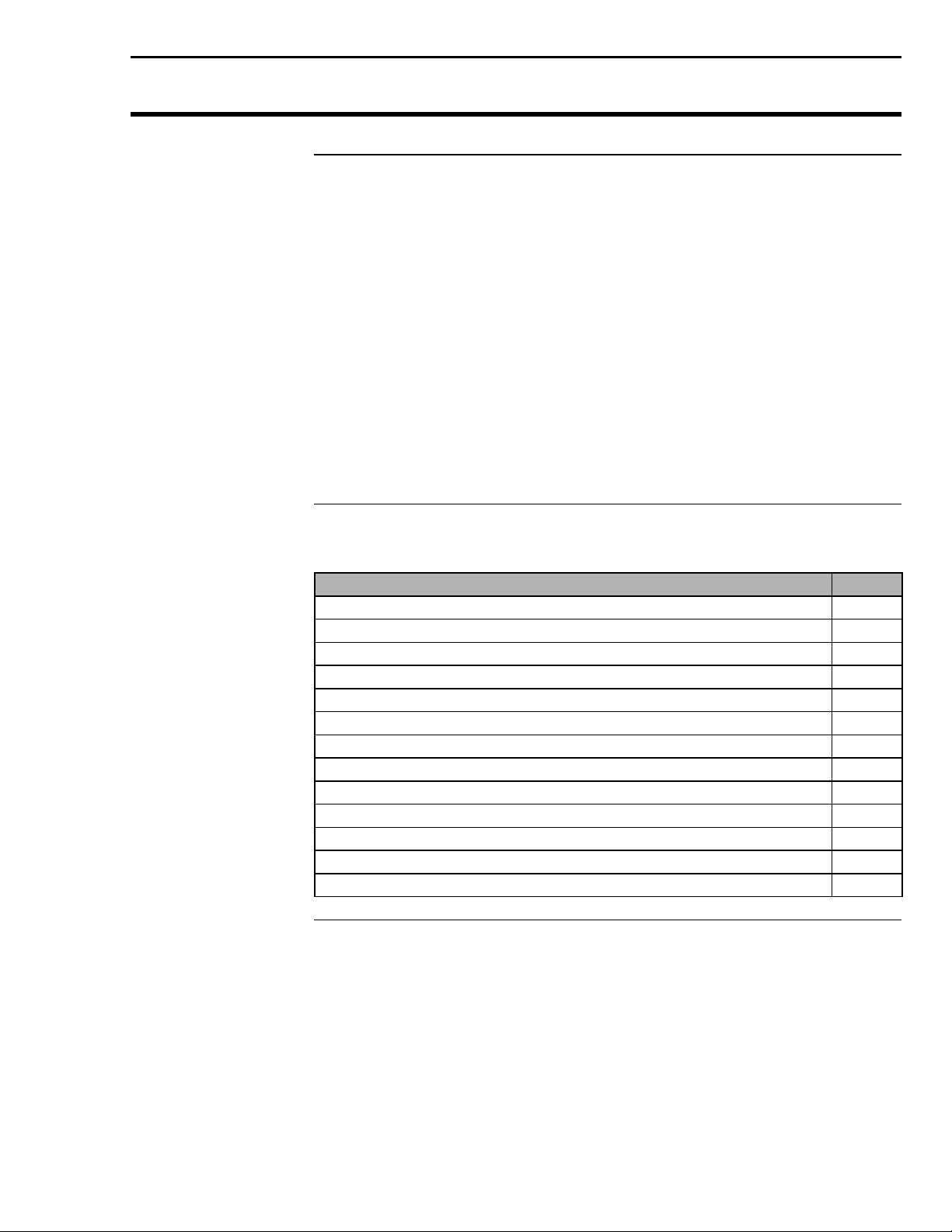
Keypad
The monitor has three groups of keys: a top group, a bottom-left group, and
a bottom-right group. When you press a key, the monitor beeps. Each key
(particularly the SETUP and MEM keys) have menu items to scroll through
by continually pressing the key to advance to the next menu item under that
key.
2-2
June 1997
Page 7
Yield Monitor 2000
Ag Leader Technology
General Description
Arrow Keys
Yes/No Keys
Figure 1: Front panel of the yield monitor 2000
When you press a key and a menu item appears, you must use the arrow
keys to scroll through a list of settings to select the appropriate setting.
Example: If you pressed the SETUP key to access “LOGGING
DEVICE=”, you must use the UP or DOWN ARROW key to set the
LOGGING DEVICE = NONE, EXT, or ?M CARD.
Note: After selecting a setting, you need not press another key to save it;
the monitor automatically remembers your selection.
When you press a key and the monitor asks you a question, press the YES
or NO key to answer the question.
Example: If you pressed the MEM key to access “COPY MEMORY TO
BACKUP?”, press the YES or NO key.
June 1997
2-3
Page 8
General Description
Yield Monitor 2000
Ag Leader Technology
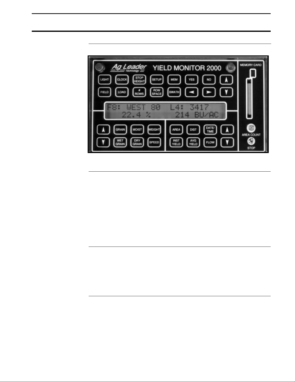
Top Keys
Bottom-Left Keys
The top group of keys is the top two rows of keys (refer to Figure 2 below).
The menu items for these keys appear only on the top line of the display,
except for two menu items accessed through the MEM key. These items
appear on the bottom line of the display. You must use the UP and DOWN
ARROW keys in the top two rows of keys to change a setting for the top
group of keys.
Figure 2: Top group of keys
The eight keys on the bottom-left of the monitor compose the bottom-left
key group. The menu items accessed through these keys appear only at the
bottom-left of the display. Use the UP and DOWN ARROW keys in the
bottom-left group to change a setting for this group of keys.
2-4
Figure 3: Bottom-left key group
June 1997
Page 9
Yield Monitor 2000
Ag Leader Technology
General Description
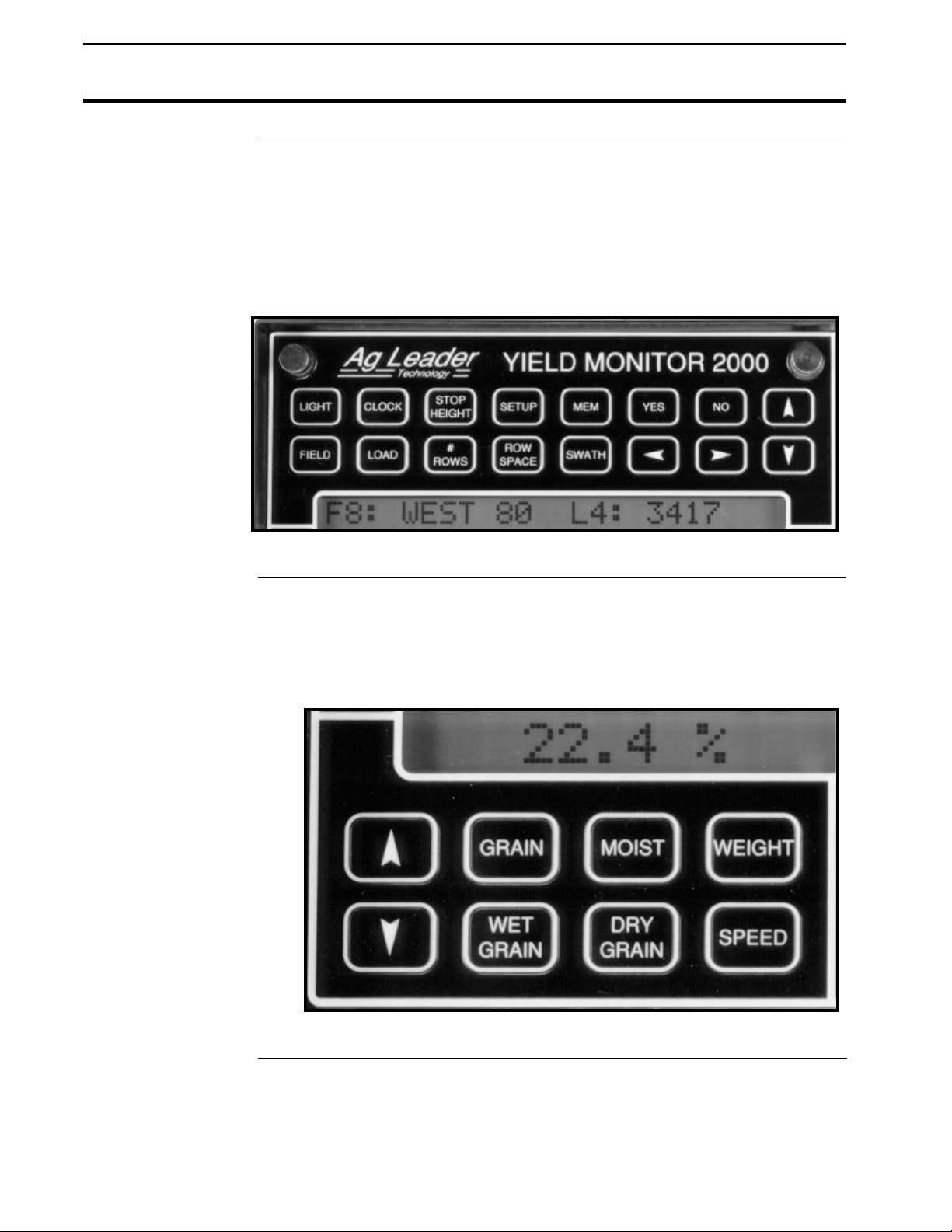
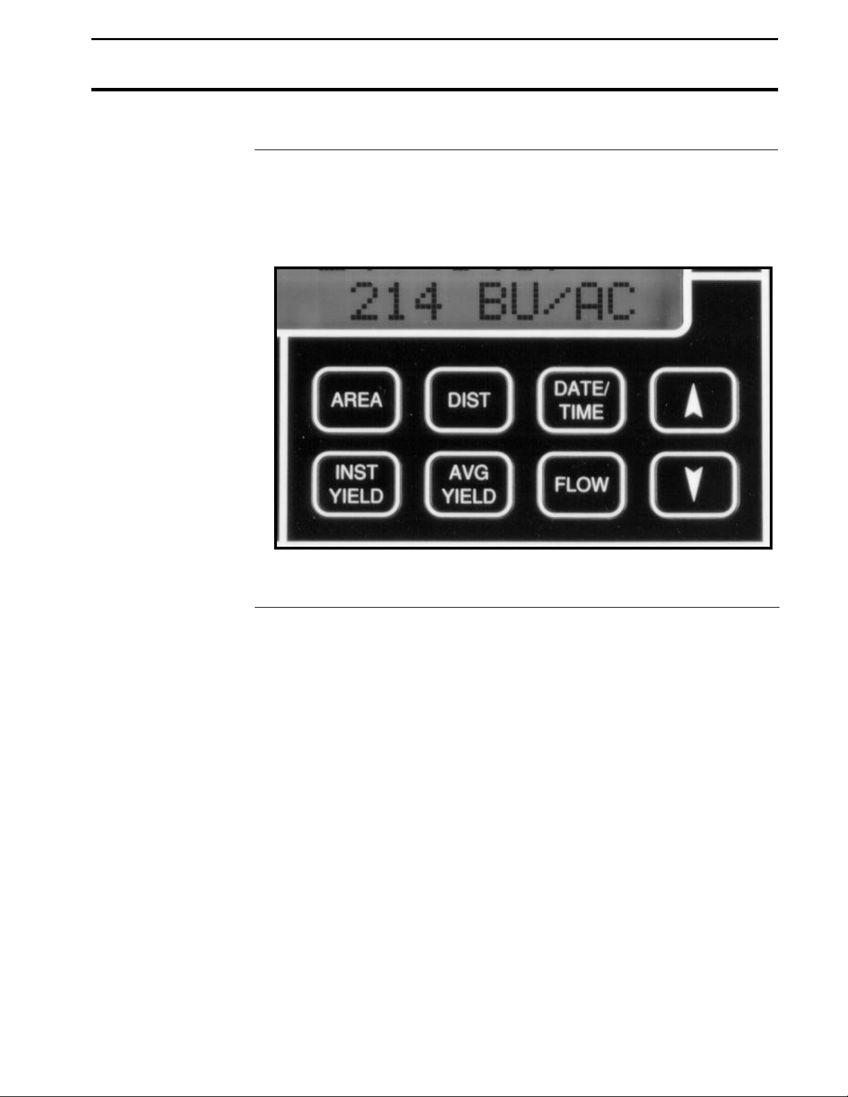
Bottom-Right Keys
The eight keys on the bottom-right of the monitor compose the bottom-right
key group. The menu items accessed through these keys appear only at the
bottom-right of the display. Use the UP and DOWN ARROW keys in the
bottom-right group to change a setting for this group of keys.
Figure 4: Bottom-right key group
June 1997
2-5
Page 10
General Description
Yield Monitor 2000
Ag Leader Technology
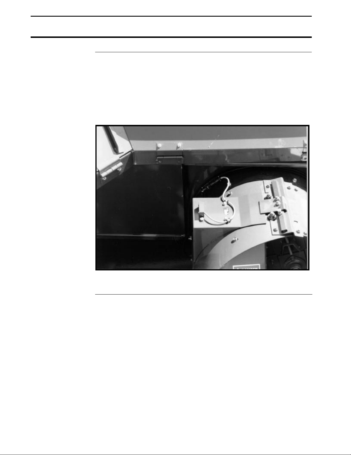
Grain Flow Sensor
Below is an example of a grain flow sensor. Your grain flow sensor may
look different, depending on which combine model you have. On all
combines, the grain flow sensor installs on top of the clean grain elevator.
The grain flow sensor measures the grain weight in pounds as you harvest.
The clean grain paddles throw the grain, as the paddles rotate around the top
sprocket, toward the grain flow sensor. The flow sensor measures the grain
weight when the grain strikes the flow sensor impact plate.
2-6
Figure 5: Grain flow sensor
June 1997
Page 11
Yield Monitor 2000
Ag Leader Technology
General Description
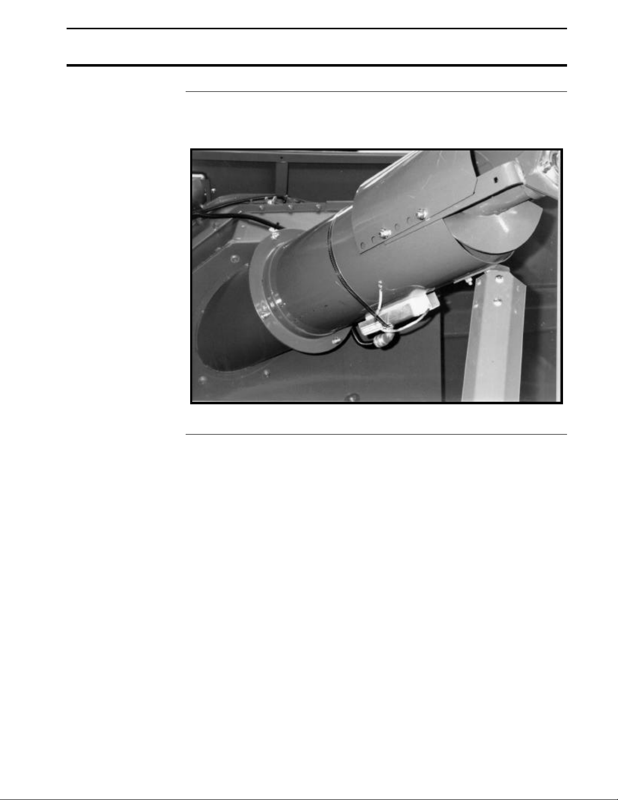
Moisture Sensor
Below is an example of a moisture sensor installed on the auger that fills the
combine grain tank.
Figure 6: Moisture sensor
June 1997
2-7
Page 12
General Description
Yield Monitor 2000
Ag Leader Technology
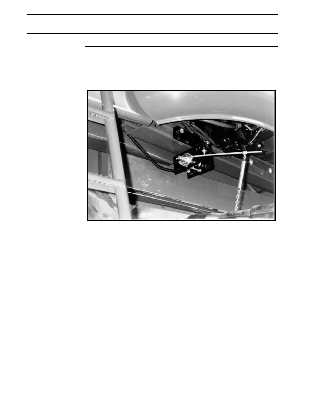
Header Height
Sensor
Below is an example of a header height sensor installed underneath a
combine cab. The header height sensor tells the monitor the position of the
combine head so that when the head is raised on the row ends as the
combine turns around, the monitor stops counting acres.
2-8
Figure 7: Header height sensor
* * *
June 1997
Page 13
Yield Monitor 2000
Ag Leader Technology
Before Setup
Using Power
Supply
Setting the
Monitor on Field,
Load
Other than for setting the stop height and calibrating the distance, the yield
monitor console does not need to be in the combine to set it up. You can use
the provided power supply (plugs into 120 v outlet) to power up the monitor
console inside your home or shop.
When going through the setup procedures, take note of which settings can
be set differently for each load. You should setup the monitor with it set to
Field 1, Load 1, because any new loads you create will use the settings for
the previously created load in that field. The monitor should come from the
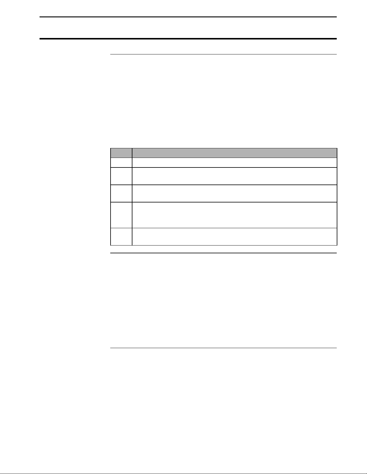
factory with only Field 1, Load 1 created. Follow the procedure below to
try to change to a different field and load to verify that only Field 1, Load 1
has been created. If there is more than one field and load already created in
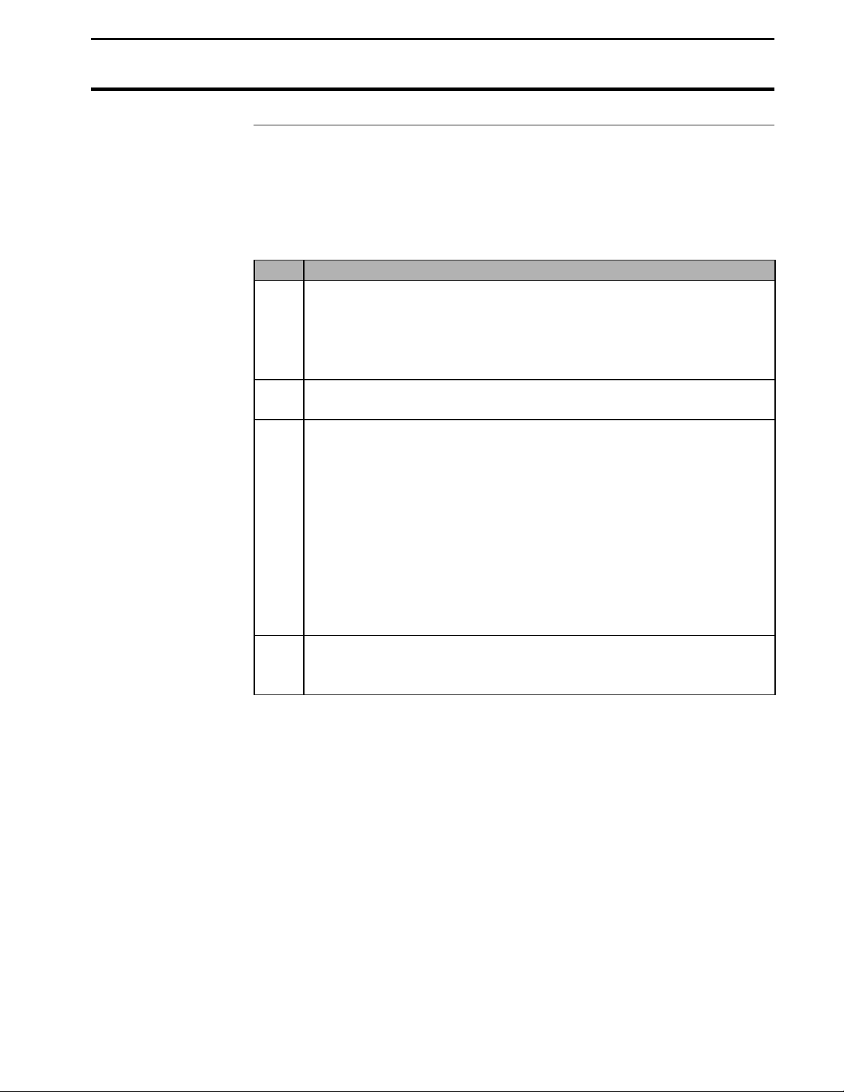
the monitor, you will have to change the settings for each one of those loads.
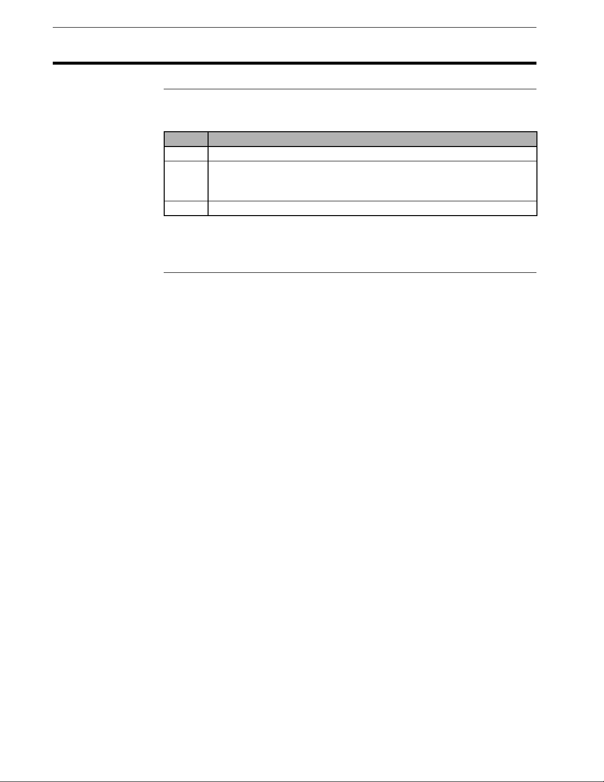
Step Action
1 Press the FIELD key to display the field only to find the last field
and created.
2 Press the top UP ARROW key until “START NEW FIELD?”
appears on the display.
Note: You can see how many fields are already created by
scrolling through the fields until START NEW FIELD? is
displayed.
3 Press the NO key.
Step Action
4 Press the LOAD key to display the field and load.
5 Press the top UP ARROW key until “START NEW LOAD?”
appears on the display.
Note: You can see how many loads are already created by
scrolling through the loads until START NEW LOAD? is
displayed.
6 Press the NO key.
* * *
June 1997
2-9
Page 14
Setting Date and Time
Yield Monitor 2000
Ag Leader Technology
Setting the Date
and Time
Follow these procedures to set the time and date:
Step
1
2
3
Press the CLOCK key to display the time and date.
Use the RIGHT ARROW key to move the cursor under the time or date
value that needs to be changed.
Use the top UP and DOWN ARROW keys to set the value.
Action
Note: The DATE/TIME key displays the date and time that the load was
created.
* * *
2-10
June 1997
Page 15

Yield Monitor 2000
Ag Leader Technology
Logging Settings
Selecting a
Logging Device
The instantaneous yield and GPS data are not recorded in the monitor’s
internal memory, but are logged to a separate device; either a memory card
or an external datalogger, which connects to the nine-pin serial port on the
monitor.
To select a logging device, press the SETUP key until “LOGGING DEVICE
=NONE or ?M CARD or EXT” appears on the display. Use the top UP or
DOWN ARROW keys to select the correct setting from the menu choices:
• NONE: Select this setting if you do not have a GPS receiver and
therefore are not logging instantaneous yield and GPS information on
either a memory card or a datalogger.
• ?M CARD: Select this setting if you have a GPS receiver and will be
logging instantaneous yield and GPS information to a memory card in
the yield monitor. The ? changes to the size of the card that was last
formatted in the monitor.
• EXT: Select this setting if you have a GPS receiver and will be logging
instantaneous yield and GPS information to an external datalogger.
Notes:
• The monitor will not log to a memory card and datalogger at the same
time.
• The LOGGING DEVICE must be set on ?M CARD for the monitor to
receive a GPS signal.
• When the monitor is turned on with the logging device set for a card, the
monitor beeps and asks you to “INSTALL CARD OR PRESS NO”
before it advances to the normal operating mode. Press the NO key if
you do not have a card and want to advance to the next operating mode.
June 1997
2-11
Page 16
Logging Settings
Yield Monitor 2000
Ag Leader Technology
Setting a Logging
Interval
To set a logging interval, press the SETUP key until “1 or 2 or 3 SEC
LOGGING INTERVAL” is displayed. Use the top UP or DOWN ARROW
keys to select 1, 2, or 3.
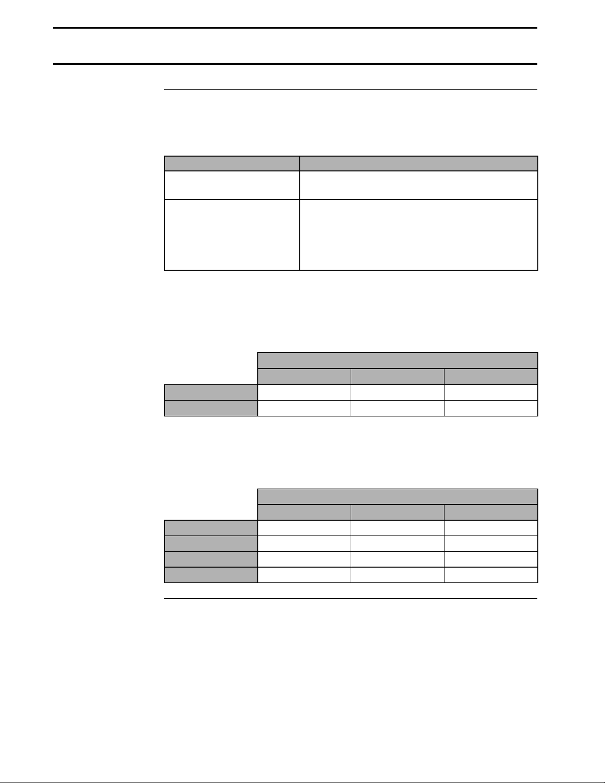
If you are . . . Then . . .
Not logging data to a
memory card,
Logging data to a card, This setting determines how often the yield and
The recommended setting is either two or three seconds. A 1-second logging
interval probably will record more yield points than you need for yield
mapping purposes.
Example:
3 mph
5 mph
Ignore this selection.
GPS information is saved to the card. It also
affects how large an area each GPS record will
represent on a map and how many hours can be
logged to a memory card before it is full.
Distance Traveled (ft)
1 sec 2 sec 3 sec
4.4 8.8 13.2
7.3 14.6 21.9
Also, a longer logging interval will allow you to log more hours of data to a
memory card. Refer to the table below to compare card space and logging
intervals:
Logging Hours Available/Logging Interval
1 sec 2 sec 3 sec
.5 M Card
1 M Card
2 M Card
4 M Card
6.7 13.5 20.3
15.7 31.5 47.3
33.8 67.6 101.4
69.8 139.7 209.5
2-12
June 1997
Page 17

Yield Monitor 2000
Ag Leader Technology
Logging Settings
Setting Log
Without Grain
Flow
To set the log without grain flow, press the SETUP key until “LOG W/O
GRAIN FLOW =NO or YES “ appears on the display.
If you are operating
the Monitor . . . Then . . .
In a combine, Set this to NO, using the top UP or DOWN
ARROW keys.
Note: The yield and GPS information is logged
only when the elevator speed is more than 250
rpm and acres are counting, or the grain flow is
more than 0 BU/HR.
On vehicles other than
combines,
Set this to YES using the top UP or DOWN
ARROW keys.
Note: GPS information is logged only when the
area count light is off (counting acres). This
allows you to perform site verification (refer to
the Options section for more information).
* * *
June 1997
2-13
Page 18
Settings Under SETUP Key
Yield Monitor 2000
Ag Leader Technology
Expand Bu Below
Std%
Number of Beeps
When Acre
Counting Stops
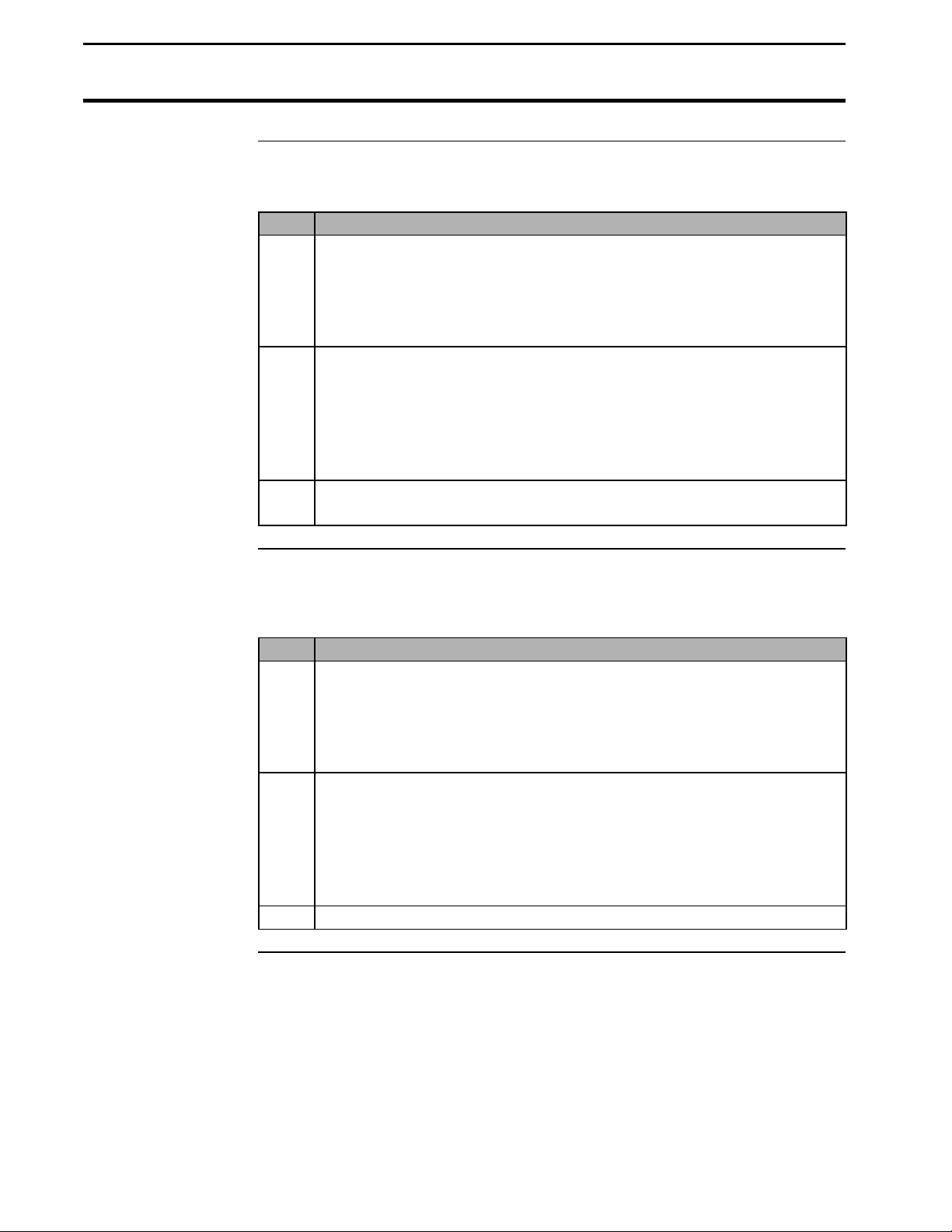
Press the SETUP key until “EXPAND BU BELOW STD%=NO or YES”
appears on the display. Use the top UP or DOWN ARROW keys to select
NO or YES.
Note: This setting applies to all loads and grains in the monitor. It can be
changed from NO to YES and vice-versa at any time.
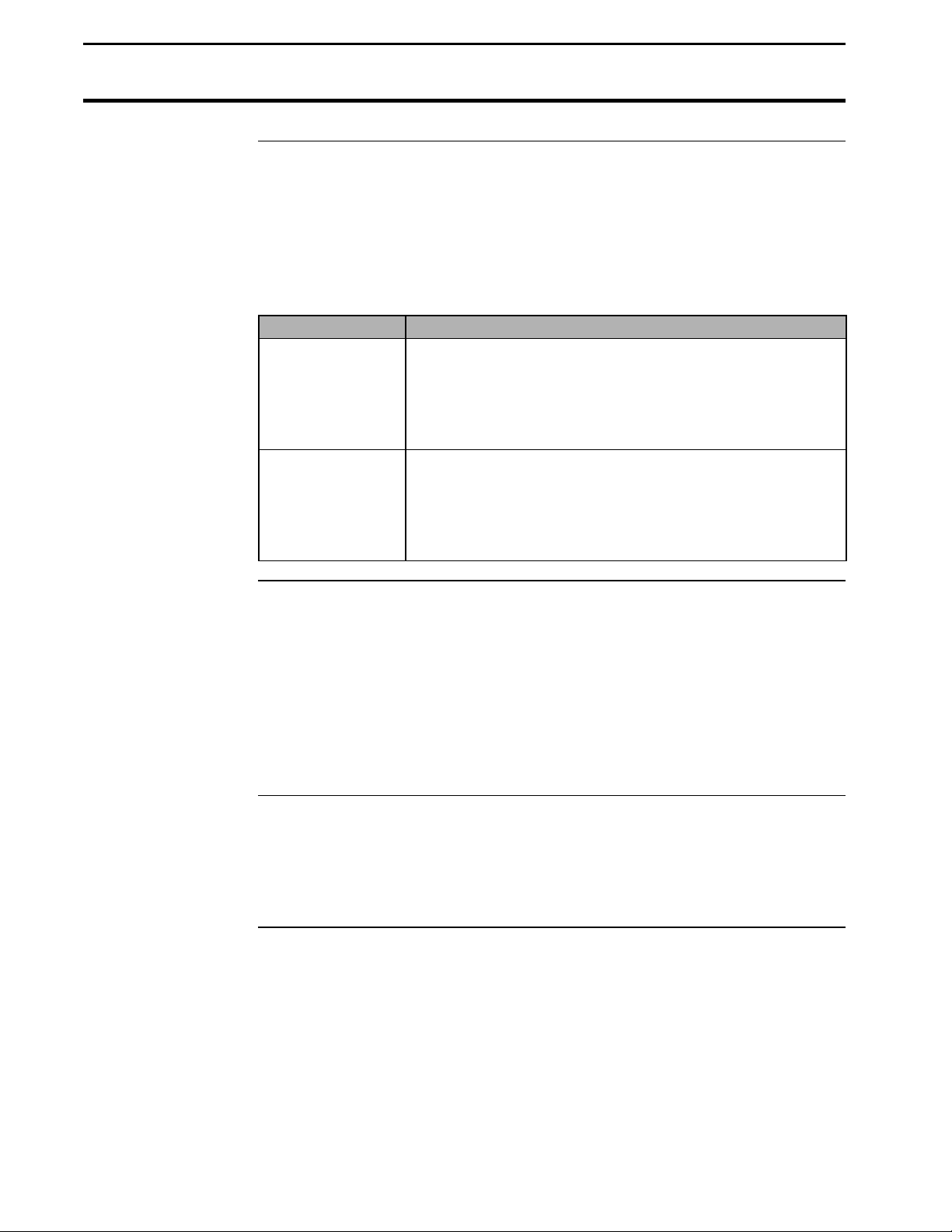
If you select . . . Then . . .
No, You prevent the monitor from adding bushels to grain
that is dryer than the dry percent moisture by which dry
bushels are calculated. This calculates all yields in terms
of actual bushels available for you to sell.
(Recommended setting).
Yes, The monitor shows a yield comparison of all loads at the
dry percent moisture. This increases the bushels of the
grain harvested below the dry percent moisture to
account for moisture lost because of excessive dryness of
the grain.
To set the number of times the monitor beeps when the head is raised and
the acres are not being counted at the end of a pass, press the SETUP key
until “MAX AC STOP BEEPS=x” appears on the display. Use the top UP
or DOWN ARROW keys to set this number from 5 to 100+.
Serial Number
2-14
Suggestion: The recommended setting is 20. Set this number high enough
so that the beeps continue until the head is lowered to give the operator an
audible signal that the head is lowered enough to begin counting acres again.
Press the SETUP key until “MONITOR SER# = xxxxxx” appears on the
display. Use the top UP or DOWN ARROW keys to set the serial number,
which is on the bottom of the monitor. The monitor serial number should be
set correctly from the factory.
June 1997
Page 19

Yield Monitor 2000
Ag Leader Technology
Settings Under SETUP Key
Other Settings
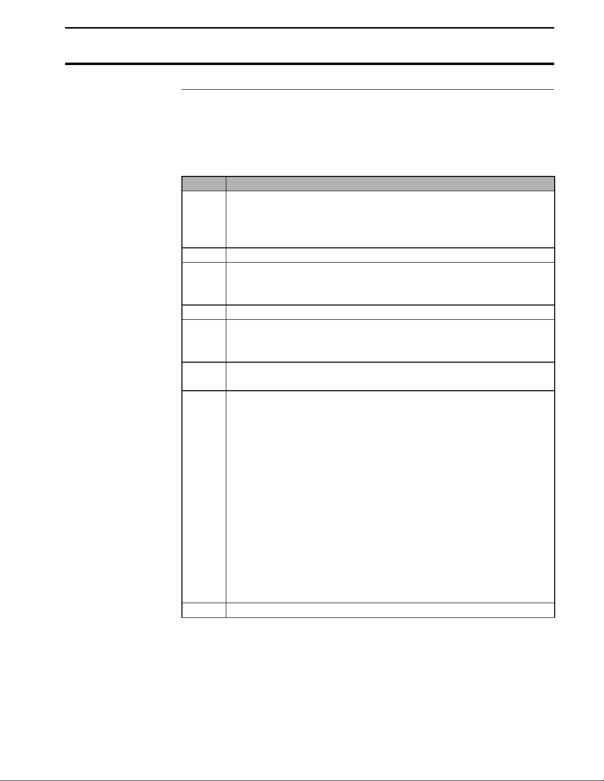
Box Calibration Press the SETUP key until “xxx BOX CAL” appears on the display, then use
Voltage Calibration Press the SETUP key until “xxx VOLTAGE CAL” appears on the display,
Sensor Calibration Press the SETUP key until “xxxx SENSOR CAL” appears on the display,
To set the remaining settings under the SETUP key, refer to the Yield
Monitor Initial Calibration Sheet in this section for the correct values.
the top UP or DOWN ARROW keys to set the number equal to the Initial
Calibration Sheet if needed. The Box calibration number should have been
set correctly at the factory.
then use the top UP or DOWN ARROW keys to set the number equal to the
number on the Initial Calibration Sheet if needed. The Voltage calibration
number should have been set correctly at the factory.
then use the top UP or DOWN ARROW keys to set the number equal to the
Initial Calibration Sheet if needed. The Sensor calibration number should
have been set correctly at the factory.
Note: If you replace the flow sensor, you must change this setting to the
value of the new sensor calibration number of the new flow sensor.
Scale Factor Press the SETUP key until “SCALE FACTOR=x.x” is displayed.
Press the top Up and DOWN ARROW key to change the scale factor to the
value on the Initial Calibration Sheet.
Important:
• Never change the scale factor during harvest. Doing so will cause the
monitor to lose calibration accuracy and you will have to set the monitor
on different grain types and recalibrate every grain type.
• If you have cleared the fields in the monitor, but have a good
calibration and will save the old calibration loads, do not adjust the
scale factor number, even if it is not set to the value on the initial
calibration sheet. If you do adjust the scale factor after saving the old
calibration loads, you will have to erase the old calibration loads and
enter new calibration loads for every grain type.
EL Pulse/Rev Press the SETUP key until “x EL PULSE/REV” appears on the display, then
use the top UP or DOWN ARROW keys to set the number equal to the
Initial Calibration Sheet if needed. EL Pulse/Rev should have been set
correctly at the factory.
June 1997
2-15
Page 20

Settings Under SETUP Key
Yield Monitor 2000
Ag Leader Technology
Tooth Sprocket Press the SETUP key until “x TOOTH SPROCKET” appears on the display,
then use the top UP or DOWN ARROW keys to set the number equal to the
Initial Calibration Sheet if needed. This number should have been set
correctly at the factory.
Note: This sprocket is at the top of the clean grain elevator and the elevator
paddles rotate around it.
TI, T2, and T3 Press the SETUP key three additional times until “T1=10,” “T2=5,” and
“T3=8” appear on the display, then check these numbers against the Initial
Calibration Sheet. If they are not set correctly, change them using the top UP
or DOWN ARROW keys. These numbers should have been set correctly at
the factory.
* * *
2-16
June 1997
Page 21
Yield Monitor 2000
Ag Leader Technology
Setting Swath
Setting Swath
Follow these procedures to set the swath.
Note: The number of rows and row space needs to be set for each grain
type. The monitor calculates swath by multiplying the number of rows by
row space.
Step Action
1 Press the GRAIN key and use the bottom-left UP or DOWN
ARROW keys to change to the grain type of which you want to set
the swath.
Note: You must have a load displayed to change the grain type.
2 Press the # ROWS key to display “x ROW CUT, x ROW HEAD”
for the selected grain type.
3 Use the RIGHT or LEFT ARROW keys to move the cursor under
the “Row Head” value. Use the top UP or DOWN ARROW keys to
set the Row Head value to the correct number of rows for the
selected grain type.
Note: The Row Head value is the permanent number of rows; do
not change it after it is set. The Row Cut value is used to calculate
acres, and it can be used to reduce the number of rows in partial
swath situations (point rows). Whenever you change the value for
the Row Head, the value for the Row Cut automatically adjusts to
equal the Row Head value.
4 Press the ROW SPACE key to display “x INCH ROWS” for the
selected grain type, then use the top UP or DOWN ARROW keys to
set the correct value.
June 1997
2-17
Page 22

Setting Swath
Yield Monitor 2000
Ag Leader Technology
Step Action
5 Repeat the above steps for each grain type that will be harvested.
Make sure to set the grain type back to the original setting for the
load after you have finished setting the swath.
Recommendations for Row Crop Heads:
• For row crops, set your row space to the planted row spacing
and your number of rows to the number of total rows of your
combine head.
Recommendations for Cutting Platform Heads:
• Set the swath in the monitor to one foot less than the actual
swath width of the head because you can rarely maintain a
constant full swath while harvesting.
• Set the monitor on a row space of 12 inches and a number of
rows that adds up to the correct swath.
Example: If your cutting platform head is 20 actual feet, set the
monitor’s swath to 19 feet by setting the row space to 12 inches and
the number of rows to 19. Setting the row space to 12 inches for
cutting platforms allows you to reduce the cutting swath by easierto-see one-foot increments when you are harvesting a partial swath.
Refer to the Swath Setting document in the operation section for
more information about partial swath.
* * *
2-18
June 1997
Page 23
Yield Monitor 2000
Ag Leader Technology
Speed Setting
Speed Setting
The monitor can record its ground speed from three different sources:
• Ground speed sensor on combine
• Radar gun
• GPS (only with Ag Leader Technology GPS 2000, Trimble AgGPS 120,
122 receivers, must have VTG data string)
The monitor has six different speed settings. The speed settings are set for
each load. With a load displayed press the DIST key until “SPD=” is
displayed. Use the bottom right UP or DOWN ARROW keys to select:
• WHL (wheels)
• TRK (tracks)
• RAD (radar)
• GPS/WHL
• GPS/TRK
• GPS/RAD
If you are getting ground speed from… Select
The combine speed sensor WHL
The combine speed sensor on combine tracks TRK
A radar gun RAD
Compatible GPS receiver and backup sensor is combine
speed sensor
Compatible GPS receiver and backup sensor is combine
speed sensor on tracks
Compatible GPS receiver and backup sensor is a radar gun GPS/RAD
GPS/WHL
GPS/TRK
Note: If you want to use a radar gun, contact Ag Leader Technology and
purchase a special adapter cable for your radar gun.
Since the speed setting is set for each load, the monitor will set the speed
setting of any newly created loads to the same setting as the previous load in
that field. Make sure that all the loads in the monitor are set to the correct
speed setting before you create new loads.
June 1997
2-19
Page 24

Speed Setting
Yield Monitor 2000
Ag Leader Technology
You have to calibrate distance for wheels, tracks, or radar speed settings,
depending on which one you use. Refer to the calibrating distance
instructions in the Calibration section.
If you are getting your ground speed from a GPS receiver, you
probably will have to change a setting on the GPS receiver to “turn on”
the ground speed feature. Even using a GPS receiver for ground speed,
you still must select either wheels, tracks, or radar as a backup speed sensor
and calibrate distance for that setting. If the GPS signal is lost, the monitor
will take readings from the backup speed sensor.
* * *
2-20
June 1997
Page 25
Yield Monitor 2000
Ag Leader Technology
Moisture Setting
Setting/Changing
Moisture
The monitor can be set on automatic moisture to receive readings from the
moisture sensor or manual moisture to use an average moisture for each
load. The monitor comes from the factory set on automatic moisture.
Follow these steps to set the moisture setting.
Note: Any new loads you create will have the same moisture setting as that
of the last load in the same field. Make sure all of the existing loads are set
on automatic moisture.
Step Action
1 Press the LOAD key to display a load on the top line of the display.
2 Press the MOIST key until “MOIST=AUTO or MAN” appears on
the display.
3 Use the bottom-left UP or DOWN ARROW key to select AUTO or
MAN.
4 If you set MOIST=MAN, you must enter an average moisture value
for that load. Press the MOIST key until “xx.x AVG %” appears on
the display.
5 Use the bottom-left UP or DOWN ARROW keys to set an average
moisture value for that load.
Buildup on the
Sensor
The moisture sensor can give readings that are too high if sticky material
from weeds or green stems buildup on the moisture sensor. This is normally
only a problem in soybeans with a lot of weeds or green stems. If you have
high moisture readings from buildup, remove the moisture sensor and clean
it. After cleaning, continue harvesting. If the buildup condition is severe,
you may not be able to keep the moisture sensor clean. In such conditions,
set the moisture for the load on manual and enter the average moisture for
that load as instructed above. After buildup conditions cease, set the
moisture back to automatic.
* * *
June 1997
2-21
Page 26
Setting DRY % Moisture,
Dry Lbs/Bu
Yield Monitor 2000
Ag Leader Technology
Setting Dry %
Moisture
Setting Dry Lbs/Bu
Follow these procedures to set dry % moisture:
Step Action
1 Press the GRAIN key until a grain type appears on the display and
use the bottom-left UP or DOWN ARROW keys to set a grain type
you will harvest.
Note: You must have the load displayed to change the grain type.
2 Press the GRAIN key until “xx.x DRY %” appears on the display,
then use the bottom-left UP or DOWN ARROW keys to set Dry %
to the moisture level you want the monitor to use to calculate dry
bushels (example: 15%-corn, 13%-soybeans). Typically, this value
is the same moisture your elevator uses to calculate the bushels for
which you are paid.
3 Repeat steps 1-2 and set DRY % for each grain type you will
harvest.
Use DRY LB/B to change the pounds/bushel value that the monitor uses to
calculate bushels.
Step Action
1 Press the GRAIN key until a grain type appears on the display and
use the bottom-left UP or DOWN ARROW keys to select a grain
type you will harvest.
Note: You must have a load displayed to change the grain type.
2 Press the GRAIN key until “xx DRY LB/B” appears on the display,
then use the bottom-left UP or DOWN ARROW keys to set the
correct value for the grain type.
Note: This value can be changed for all grain types except corn (56
lbs/bu), soybeans (60 lbs/bu), and wheat (60 lbs/bu).
3 Repeat steps 1-2 and set dry lbs/bu for each grain type you will use.
* * *
2-22
June 1997
Page 27
Yield Monitor 2000
Ag Leader Technology
Setting Initial Calibration
Numbers
Setting Initial
Calibration
Numbers
Refer to the Yield Monitor Initial Calibration Sheet in this section to set the
calibration numbers for each grain type.
Follow these procedures to set the calibration numbers for each grain type:
Step Action
1 Press the GRAIN key and use the bottom-left UP or DOWN
ARROW keys to select a grain type that you will harvest.
Note: You must have a load displayed to change the grain type.
2 Press the GRAIN key until “M1=xxx” appears on the display.
3 Check the value shown for this grain type against that on the Initial
Calibration Sheet. If the value is not correct, use the bottom-left
UP or DOWN ARROW keys to set it.
4 Press the GRAIN key again to advance to the S1 value.
5 Check the value shown for this grain type against that on the Initial
Calibration Sheet. If this value is not correct, use the bottom-left
UP or DOWN ARROW keys to set it.
6 If grain weight (pounds) has never been calibrated for this grain
type, press the GRAIN key to advance to the C11 value.
7 Check the value shown for this grain type against that on the Initial
Calibration Sheet. If this value is not correct, use the bottom-left
UP or DOWN ARROW keys to set it.
Notes:
• You may not be able to set C11 to the exact number as on the
Initial Calibration Sheet. Set it as close to the initial number as
you can.
• When you change C11, the C2 through C10 values change
proportionally (they may not agree with the numbers on the
Initial Calibration Sheet, but they will be close enough).
• If pounds has been calibrated previously for this grain type, do
not change C11.
8 Press the GRAIN key until the grain type appears on the display.
June 1997
2-23
Page 28

Setting Initial Calibration
Numbers
Step Action
9 Press the bottom-left UP or DOWN ARROW keys to change the
10 Repeat Step 9 for every grain type you will harvest. When you
Yield Monitor 2000
Ag Leader Technology
grain type displayed to another grain that you will harvest, then set
the calibration numbers for this grain type as described above.
have set these values for every grain type, press the LOAD key to
display field and load on the top line, and set the grain type for this
field and load.
Copy Memory to
Backup
To ensure that you do not lose the grain calibration settings, immediately
copy the memory to backup. Press the MEM key until “COPY MEMORY
TO BACKUP” appears on the top line of the display, then press the YES
key.
* * *
2-24
June 1997
Page 29

Yield Monitor 2000
Ag Leader Technology
Starting, Naming Fields, Loads
Recommendations
Starting, Naming
Fields and Loads
Follow these guidelines when starting and naming the fields and loads:
• It is strongly recommended that you create and name the fields and loads
before harvest because this will save you time during harvest.
• Select field names that you can use year after year; do not try to use the
field numbers of the monitor to keep track of the fields from year to year.
The monitor’s data recording system works best if you select a name for
a field and reuse the same name in successive years for that field’s yield
data.
There are two ways to start and name your fields and loads:
• Connect the monitor to a computer that runs Windows 3.1 or
Windows 95
• Start and name fields and loads on the monitor
Note: You may want to start and name the fields only because you may not
know how many loads you want to create until harvest. You can always
create and name fields and loads or change field and load names on the
monitor during harvest.
Starting, Naming
Fields and Loads
With a Computer
To create and name the fields and loads with a computer, you must first
connect the yield monitor to the computer and establish communication.
Refer to the “Connecting the Monitor to Your PC” instructions in the
Printing Field/Load Summary document in the Operation section for
information about establishing communication between your computer and
yield monitor. If you have Windows 95 you will use the HyperTerminal
program. If you have Windows 3.1 you will use the Terminal program.
After you have established communication, “Type PRINT, NAME, or
START & press Enter” will appear on the computer display, and the monitor
will be set to READY TO PRINT.
You must enter commands on the computer to start and name fields and
loads and to select a grain type. When you enter a command on the
computer, the display on the monitor will change accordingly. After you
enter a command on the computer, “Type PRINT, NAME, or START &
press Enter” is displayed again on the computer indicating you can enter
another command. Refer to the commands and instructions below.
June 1997
2-25
Page 30
Starting, Naming Fields, Loads
On computer press… To…
Follow the procedures below to start and name fields and loads and to select
a grain type for each field from the computer.
Step Action
1 With the monitor set “READY TO PRINT” and “Type PRINT,
NAME, or START & press Enter” displayed on the computer, press
the F key on the computer and press the Enter key. This will
display a field and its grain type on the monitor.
2 To change to the field or to create the field you want to name, press
the U key to increase or the D key to decrease the field number and
press the Enter key.
Yield Monitor 2000
Ag Leader Technology
F Display Field
L Display Load
U Increase Field or Load
D Decrease Field or Load
GU Increase Grain Type
GD Decrease Grain Type
Y Answer Yes to question
N Answer No to question
When you increase the field to a field that has not been created yet,
the monitor will display “START NEW FIELD?”. Press the Y key
on the computer and press the Enter key. Refer to step 3 to change
the grain type.
2-26
June 1997
Page 31

Yield Monitor 2000
Ag Leader Technology
Step Action
3 Set the grain type for the field by pressing the GU keys to increase
Starting, Naming Fields, Loads
the grain type or the GD keys to decrease the grain type and press
the Enter key. The grain types are listed below in order.
• SOYBEANS
• CORN
• WHEAT
• OATS
• RYE
• BARLEY
• SORGHUM
• POPCORN
• EDIBL BEANS
• CORN 2
• CANOLA
• RICE
• SUNFLOWERS
• CORN 3
• CORN 3
• OPT GRAIN 1
Note: You can only have one grain type per field. When you set
the grain type for the field, the monitor is actually setting the grain
type for the load (will be load one if no loads have been created yet).
When you create more loads in that field, the grain type of the new
loads will be the same as the grain type of the previous load. If loads
have already been created in the field, and you are setting the grain
type with the field only displayed, you actually will be setting the
grain type for only load one in the field. You will have to display
each load previously created in the field and change the grain type for
each load.
4
To name the field, type name and press the Enter key and then enter
a name up to eight characters long at the “New Name:” prompt on
the computer screen. Press the Enter key to accept the new name.
Note: Choose a name for each field that you will use year after year
for that field.
5 Repeat steps 1-4 and create and name all your fields.
6 Once you have named all of the fields, set the monitor on the first
field by pressing the F key and then the D key on the computer to
scroll to the very first field.
June 1997
2-27
Page 32

Starting, Naming Fields, Loads
Step Action
7
Press the L key on the computer and then hit the Enter key to
display the load. Press the U key to increase or the D key to
decrease the load to the first load to name and press the Enter key.
When you increase the load to a load that has not been created yet,
the monitor will display “START NEW LOAD?”. Press the Y key
on the computer and press the Enter key to start a new load.
8
Type “name” on the computer and press the Enter key. Type a
name up to 8 characters long at the “New Name:” prompt on the
computer and press the Enter key. You will see the name appear.
Suggestions:
It is common to use Load 1 for the end rows, so you might want to
name it ENDROWS. Other loads could be designated for varieties or
hybrids.
Example: “L2:P3417” “L3:P3489”
9 Repeat steps 7-8 and name all the loads in that field.
10
Change to the next field by pressing the F key and press the Enter
key and the press the U key to increase or the D key to decrease the
field to the next field you want to name the loads and press the Enter
key.
11 Repeat step 10 and start and name all the loads in every field.
Yield Monitor 2000
Ag Leader Technology
2-28
June 1997
Page 33

Yield Monitor 2000
Ag Leader Technology
Starting, Naming Fields, Loads
Starting, Naming
Fields With the
Monitor
Follow these steps to create and name fields with the monitor:
Step Action
1 Press the FIELD key to display field only on the top line.
2 Use the RIGHT ARROW key to move the cursor (the line under the
arrow or colon just to the right of the field number) to the right one
or more spaces.
3 Press the top UP or DOWN ARROW key scroll through symbols,
numbers, or letters you can use to name the field. Move the cursor to
the right one space to enter another character. You can enter up to
eight characters for a name. To remove a character, scroll to the
space located between the 9 and A.
Example:
F1:WEST8
CORN 0.0 AV B/A
Note:
• The monitor beeps each time the character changes. If you hold
down the top UP or DOWN ARROW key, you will notice that
the characters change slowly for the first few, but then begin
changing very rapidly. This allows you to easily make a change of
one or two characters while allowing you to scroll through all the
available characters rapidly.
• Choose a name for each field that you will use year after year for
that field.
4 Press the top UP ARROW key to try to advance to the next field. If
the next field has not been created, the top line displays “START
NEW FIELD?”
5 Press the YES key to start a new field. The monitor beeps four times
quickly, displays the field number and “SET GRAIN/PRESS YES”
on the top line, and displays the grain type set for the previous field
on the bottom left.
6 If the grain type displayed is not correct for this field, use the
bottom-left UP or DOWN ARROW keys to change it.
7 When the grain type is set correctly, press the YES key.
8 Name the field and repeat steps 1 through 7 for each field you want
to create.
When you have created all the fields you need, scroll back to the first field
that you expect to harvest.
June 1997
2-29
Page 34

Starting, Naming Fields, Loads
Yield Monitor 2000
Ag Leader Technology
Starting, Naming
Loads With the
Monitor
The next step is to create and name the loads within the fields. You need to
consider how you want to logically subdivide the fields into loads.
Note: It is common to designate Load 1 for the end rows and name it
“ENDROWS”. The other loads could be designated for a certain variety or
hybrid. Name these loads the hybrid or variety name (example:
“L2:P3417”). Because you may not know how many loads you want to
create until harvest, you can create and name more loads any time.
Step Action
1 Press the LOAD key to display field and load on the top line.
2 With the cursor under the load, use the RIGHT ARROW key to
move the cursor to the right one space.
3 Press the top-right UP ARROW key to change the blank space to
either a symbol, number, or letter. You can enter up to eight
characters for a load name.
Example:
F1:WEST8 L1:HYBRID
CORN 0.0 AV B/A
4 Press the LOAD key to display field and load on the top line to
create a load.
5 Press the top-right UP ARROW key to scroll to the next load. If
the next load has not already been created, the monitor displays
“START NEW LOAD?” on the top line.
6 Press the YES key to start a new load.
7 Name the new load and create and name loads for all the fields you
have created.
8 Repeat steps 1 through 7 for each field you want to create.
Settings Performed
in the Combine
2-30
All the settings up to this point could be completed with the monitor out of
the combine and plugged into a wall outlet. The stop height setting and the
distance calibration must be completed with the monitor in the combine cab.
* * *
June 1997
Page 35

Yield Monitor 2000
Ag Leader Technology
Setting Stop Height
Setting Area Count
Stop Height
The monitor automatically takes readings from the header sensor so that
when you lift the combine’s head at the end of the rows to turn around, and
stops counting area if the head is raised high enough. The stop height
number setting determines how high the head must be raised at the ends of
the rows to stop counting area. The stop height can be set differently for
each grain type.
Follow these procedures to set the stop height:
Step Action
1 Set the monitor on a data load (load with an arrow to the right of the
load number (L1->).
2 Press the GRAIN key to display the grain type. Use the bottom-left
UP or DOWN ARROW keys to change the grain type.
Note: You must have a load displayed to change the grain type.
3 Press the STOP HEIGHT key to display the stop height value
(typically, the value is between 55 and 75).
4 Position the head at the height at which you want to stop counting
acres (this must be slightly higher than the height at which you run
the head while harvesting).
5 Put the area count switch in the up position. If the AREA COUNT
LIGHT is off, use the top DOWN ARROW key to decrease the stop
height value until the light turns on.
Note: When the light is off, you are counting acres. When it is on,
you are not counting acres.
6 If the AREA COUNT LIGHT is on, use the top UP ARROW key to
increase the stop height value until the light turns off. Then decrease
the value by one, which should make the light turn on.
7 Change the grain type to a different grain and set the stop height
value for that grain type.
8 Repeat steps 1 through 7 for all grain types you will harvest. Make
sure you change the grain type for the load back to its original
setting.
Note: You may want to fine-tune the stop height when you begin
harvesting.
* * *
June 1997
2-31
Page 36

Copying Memory to Backup
Yield Monitor 2000
Ag Leader Technology
Copy Memory to
Backup
Calibrating
Distance,
Temperature and
for Vibration
Once you have finished setting up the monitor you should backup the
settings in the main memory to the backup memory. When you start
harvesting you should back up the monitor at lease once a day. Refer to the
procedures below.
Step Action
1 Press the MEM key until “COPY MEMORY TO BACKUP?” is
displayed.
2 Press YES key.
-or-
3 Shut the monitor off and “COPY MEMORY TO BACKUP
BEFORE POWER OFF?” is displayed.
4 Press YES key.
You should put the monitor back in the cab if you have not already done so
and refer to the Calibration Section and calibrate for distance, temperature
and vibration to complete the setup of the monitor. You can not calibrate
for moisture or grain weight until you start harvesting.
* * *
2-32
June 1997
Page 37

Yield Monitor 2000
Ag Leader Technology
Calibration Overview
Introduction
Before you begin using the monitor, you must calibrate its settings so that it
may provide accurate data. These subjects will provide directions for
calibration:
Subject Page
Calibrating Distance 3-2
Calibrating Temperature 3-5
Calibrating for Vibration (C1) 3-6
Calibrating Moisture 3-8
Calibrating Grain Weight 3-11
* * *
June 1997
3-1
Page 38

Calibrating Distance
Yield Monitor 2000
Ag Leader Technology
Preparing to
Calibrate Distance
You must do the following before you begin calibrating distance:
• Accurately measure a known distance, setting flags or making a mark at
each end
Notes:
• A distance of at least 200 feet is desired to obtain an accurate
calibration.
• For maximum accuracy, calibrate on a ground surface that is at least
somewhat similar to field conditions (you can also calibrate while
harvesting if you know or measure a precise distance in the field).
• Change to a data load (load with arrow to right of load number L1->)
with no distance.
Follow these procedures to change to a data load.:
Step Action
1
• Start a new load by pressing the top UP ARROW key with the
load displayed and scroll past the last load.
or
• Make an existing load the data load by pressing the MEM key
until “CHANGE TO THIS LOAD?” appears on the display, then
press the YES key.
2 Press the DIST key to display “x FT,” and check that 0 feet are in the
data load. If there are feet in the load, start a new load according to
step 1.
3-2
June 1997
Page 39

Yield Monitor 2000
Ag Leader Technology
Calibrating Distance
Calibrating
Distance
Follow these procedures to calibrate the monitor for distance:
Step Action
1 Press the DIST key until “SPD=WHL or TRK or RAD or
GPS/WHL or GPS/TRK or GPS/RAD” is displayed. Use the
lower right UP or DOWN ARROW keys to change “SPD=” to:
WHL if you are using the wheel speed sensor on the combine for
ground speed
TRK if you are using the track speed sensor on the combine for
ground speed
RAD if you are using a radar gun for ground speed
Note:
If you are using a GPS receiver for ground speed (monitor set on
SPD=GPS/WHL, GPS/TRK or GPS/RAD) you still need to set
speed equal to either WHL, TRK or RAD and do a distance
calibration for the backup speed sensor. The monitor will start
using the selected backup speed sensor if the GPS signal is lost.
Do not set “SPD=” to anyone of the three GPS settings when
calibrating distance.
Example:
If you are using your GPS receiver as the ground speed sensor and
you are using the wheel speed sensor on the combine as the backup
speed sensor, you must calibrate distance for the wheel speed
sensor by setting SPD=WHL. However, the speed setting you
should leave the monitor set on for field operation is
SPD=GPS/WHL.
2 With the AREA COUNT SWITCH down and the red light on
(distance and area counting stopped), pick a spot on the combine
and align it with the marking at one end of the measured distance.
3 Flip the AREA COUNT SWITCH up, and, if necessary, lower the
head enough to make the red light turn off.
4 Press the DIST key until “x FT” is displayed.
5 Drive the measured distance, stopping at the end mark.
6 Flip the AREA COUNT SWITCH down (red light turns on).
June 1997
3-3
Page 40

Calibrating Distance
Yield Monitor 2000
Ag Leader Technology
Step Action
7 Use the lower-right UP or DOWN ARROW key to increase or
decrease the number of feet displayed so that it is equal to the
distance measured.
Notes:
• When you change the feet measurement on the display, you are
changing the distance calibration number. You can see the
number if you press the DIST key until “xxxxpls/100’ “ appears
on the display.
• It may take several increment or decrement cycles to go from
where the measured distance is 1 foot under to 1 foot over the
measured distance. Count the number of beeps and set it in the
middle of this range.
Clearing Feet Out
of the Load
Calibrating
Distance
Accurately
Follow these procedures to clear the feet out of the load:
Step Action
1 Press the MEM key until “CLEAR DATA IN THIS LOAD?”
appears on the display.
2 Press the YES key.
3 After the Monitor beeps four times and “ARE YOU REALLY
SURE? YOU WILL LOSE DATA” appears on the display, press
the YES key again.
4 If you are using a GPS receiver for ground speed, change the
“SPD=” setting back to the correct GPS setting for that load.
Turn the combine around and repeat the above steps for calibrating distance
and clearing feet out of the load until you are confident that you have set the
distance calibration as accurately as you can.
Note: Perform this check while traveling forward only because combine
tires roll slightly differently in forward than they do in reverse.
3-4
* * *
June 1997
Page 41

Yield Monitor 2000
Ag Leader Technology
Calibrating Temperature
Introduction
Calibrating
Temperature
The moisture sensor contains a temperature sensor, which measures the
grain temperature for use in adjusting the measured grain moisture.
Follow these procedures to calibrate temperature:
Step Action
1 Press the MOIST key until the temperature reading “xx DEG F”
appears at the bottom-left of the display.
2 Use the bottom-left UP or DOWN ARROW keys to set the
temperature to the ambient air temperature, which automatically
changes “x T OFFSET”. (You can press the MOIST key to display
“x T OFFSET”).
Notes:
• For accurate moisture readings, it is more important that you not change
the temperature offset while harvesting than it is to have it set exactly
right. Therefore, after you set it, leave it at that setting.
• To calibrate temperature accurately, you must obtain an accurate
ambient air temperature after the temperature has been relatively stable
for several hours.
• If the combine has sat overnight, the moisture sensor may be cooler than
ambient air temperature because the air can warm much more quickly
than the sheet metal of the combine. If you are adjusting temperature
without harvesting grain, it is best to do it when the combine has been
sitting in a constant ambient temperature for several hours.
• If you set temperature while harvesting grain, the sensor measures grain
temperature, which will be close to ambient if the air temperature has
been constant for several hours.
• To get the most accurate setting, check grain temperature at the combine
with a thermometer.
* * *
June 1997
3-5
Page 42

Calibrating for Vibration (C1)
Yield Monitor 2000
Ag Leader Technology
Introduction
Calibration
Procedure
The yield monitor must be calibrated to eliminate false grain flow readings
that are caused by vibration forces when the combine runs empty. Press the
GRAIN key to set the C1 number to eliminate the false grain flow readings.
C1 must be set for each grain type you harvest.
Follow these procedures to calibrate for vibration (C1):
Step Action
1 Set the monitor on a data load (load with an arrow to the right of the
load number, L1->) that has no data in it and is set for the correct
grain type.
Note: To set the monitor on a data load, follow these steps:
Step Action
1 Either start a new load or display a load that was already
created.
2 Press the MEM key until “CHANGE TO THIS LOAD?”
appears on the display.
3 Press the YES key.
2 Press the GRAIN key until “C1=x” appears on the display.
3 Use the bottom-left DOWN ARROW key to set C1=0.
4 Press the FLOW key to display “x BU/HR”.
5 Engage the separator and run the combine empty and at full throttle
and watch the flow in bu/hr.
6 With the separator running, increase the C1 number using the
bottom-left UP or DOWN ARROW keys until the flow in bu/hr is
reduced to a zero reading. Because the vibration forces are not
constant, it may be hard to adjust C1 so that there is always a zero
flow. You should adjust C1 high enough, so that there is only one
flow reading over zero in a 10 second period.
3-6
Note:
• You should have the head on the combine when you perform
steps 5 and 6. A head adds to the combine vibration, particularly
cutting platform heads.
• The final C1 value should be between 0 and 250.
June 1997
Page 43

Yield Monitor 2000
Ag Leader Technology
Step Action
7 Press the MEM key until “CLEAR DATA IN THIS LOAD?”
8 Press the YES key twice to erase the data in the load so that the load
9 Repeat the above steps for every grain type you harvest.
Calibrating for Vibration (C1)
appears on the display.
can be used for yield data.
* * *
June 1997
3-7
Page 44

Calibrating Moisture
Yield Monitor 2000
Ag Leader Technology
Important Notes
Grain Moisture
Calibration
Procedure
• You must calibrate the monitor for grain moisture for each grain type
before the monitor can accurately measure grain moisture and dry
bushels. Moisture is calibrated on one load only.
• Make sure the temperature has been properly calibrated before
calibrating moisture. Refer to the instructions in this section for
calibrating temperature.
• You do not have to calibrate for grain moisture at the beginning of the
season to get accurate results, although it is recommended. You can wait
for a more convenient time in the season to calibrate moisture. The
monitor will automatically correct all grain moistures for all the loads
that were previously harvested of that grain type.
Follow these procedures to calibrate the monitor for grain moisture:
Step Action
1 Set the monitor on a data load (arrow to the right of load number,
i.e., L1à) of the correct grain type that has no data in it, and harvest
a load of grain into the monitor. Ideally, the load should be only one
to two combine hoppers of grain that varies little in moisture content.
Calibrating moisture using a smaller load will make it less likely for
the moisture to vary within the load which will give a more accurate
calibration.
3-8
Notes:
• To set the monitor on a data load:
• Either start a new load
-or-
• Display a load already created.
• Press the MEM key.
• Press the YES key when the message “CHANGE TO
THIS LOAD?” appears at the bottom of the display.
• Press the MOIST key to check that the data load the monitor is
set on is set to MOIST=AUTO”.
2 Use a reference moisture sensor and take readings from several grain
samples from that load.
Caution: Do NOT enter the grain tank when the separator is
running.
June 1997
Page 45

Yield Monitor 2000
Ag Leader Technology
Step Action
3 Make sure the moisture readings do not vary more than 4 to 5
4 Calculate the average actual moisture from the readings taken from
5 Make sure the load for which the moisture samples were taken is
6 Press the MOIST key until “xx.x AVG %” is displayed on the
7 To calibrate for moisture, use the lower left UP or DOWN ARROW
Calibrating Moisture
percentage points from the different grain samples. If they do, you
may not be able to accurately calculate the actual average moisture.
If this is the case, harvest another load.
the grain samples.
displayed on the top line.
bottom left line.
keys to change the displayed moisture reading on the monitor to the
actual average moisture obtained from the reference moisture tester.
This automatically adjusts the moisture of every previous load in the
monitor for that grain type.
Buildup on the
Moisture Sensor
that cause high
readings
Note: When you change the displayed moisture with the arrow keys,
the monitor automatically changes the “x.x% OFFSET” value under
the MOIST key and vice versachanging the offset value
automatically changes the displayed moisture readings. Typical offset
values are 0.0corn, +2.0wheat, +4.5soybeans.
Make sure the moisture sensor does not have a buildup of sticky material on
it (this can be a problem with soybeans) when you are harvesting the
moisture calibration load. You will know there is buildup if your moisture is
reading 8-10 or more percentage points too high. If you calibrate moisture
when the moisture sensor has a sticky buildup, your calibration will be
inaccurate.
If you have a severe buildup problem on the moisture sensor, follow these
procedures to set those loads to manual moisture. Refer to the Operation
section for more details.
Step Action
1 Press the MOIST key.
2 Use the lower left UP or DOWN ARROW keys to set
“MOIST=MAN”.
June 1997
3-9
Page 46

Calibrating Moisture
Yield Monitor 2000
Ag Leader Technology
Step Action
3 Press the MOIST key again to display “xx.x AVG %”.
4 Use the lower left UP or DOWN ARROW keys to change the “xx.x
AVG %” value to the average actual moisture.
Press the GRAIN key to check “xx.x DRY %” for the grain type. Verify that
it is set to the moisture you want the monitor to use to calculate dry bushels.
* * *
3-10
June 1997
Page 47

Yield Monitor 2000
Ag Leader Technology
Calibrating Grain Weight
Before You Begin
Calibrate the moisture before calibrating grain weight. Refer to the
instructions in this section for moisture calibration.
You must calibrate the monitor for grain weight (lbs) for each grain type
before the monitor will accurately measure bushels. You should be able to
calibrate your yield monitor for grain weight to an average error of 1 percent
to 3 percent.
IMPORTANT: Before calibrating, it is extremely important that you
check the clearance between the tip of the clean grain elevator paddles
and the inside of the elevator housing at the top of the clean grain
elevator. There must be ½ inch or less clearance as the paddle rotates
around the top sprocket. If your clearance is more than ½ inch, your
calibration will likely be inaccurate.
You do not have to calibrate grain weight at the beginning of the season to
get accurate results, although it is recommended. Each time you calibrate the
monitor, it will automatically correct all grain weights for all the loads of that
grain type that were previously harvested.
Note: Because the monitor measures the weight, not the volume, of the
grain hitting the flow sensor, test weight and different varieties do not cause
calibration inaccuracies.
C Numbers
The 11 C Numbers, C1 through C11 determine the pounds that the monitor
calculates from the data that it records into your loads as you harvest. You
can display the C numbers under the GRAIN key. Changing the C numbers
changes the pounds in every load set on that grain type for which the C
numbers were changed. Anytime you calibrate the monitor it adjusts the C
numbers automatically.
The C numbers initially should be set to the same values that appear on
your initial calibration sheet. (Refer to the Setup section). With the C
numbers set at their initial value, your accuracy of grain weight measurement
may be only in the +/- 20 percent range.
Note: After the monitor adjusts the C numbers when calibration is complete,
do not set them back to the initial values from the machine calibration sheet.
If you do, you will change calibration accuracy.
June 1997
3-11
Page 48

Calibrating Grain Weight
The C1 number is set to eliminate extra pounds that would be recorded from
vibration when the separator is engaged and the combine is running empty.
The C1 number is set by the operator manually and will not automatically
change when the monitor is calibrated. Refer to the instructions on setting
C1 in the Vibration calibration section.
Yield Monitor 2000
Ag Leader Technology
Calibration Loads
Grain Flow Rate
The Monitor calibrates itself on the basis of actual load weights you enter
into the monitor. You obtain actual load weights by weighing the grain of a
load in the monitor on accurate scales (elevator, calibrated weigh wagon).
When you enter an actual weight for a load into the monitor, that load
becomes a calibration load. Any load (that has pounds of grain in it) in any
field in the monitor can be a calibration load at anytime.
The monitor’s calibration can be very accurate because the monitor
calibrates a specific calibration value for virtually every level of grain flow
rate or amount of grain that goes through your combine that the flow sensor
is measuring. The grain flow rate that your flow sensor measures changes as
the travel speed of the combine changes or the crop yield changes.
Note: The monitor, however, can calibrate only for the grain flow rates that
were moving through your combine at the time the calibration loads were
harvested. You must change your grain flow rates (by varying travel speed
or swath width) from one calibration load to the next or grain weight will
not be measured accurately.
Calibration
Accuracy
3-12
For accurate calibration results, you must obtain at least six calibration
loads (loads with actual weights). Each calibration load must be
harvested under a different grain flow rate by varying either your
travel speed or your swath width. You should achieve accurate calibration
results with no more than 10 to 15 calibration loads; if you do not,
something is wrong and you need to troubleshoot grain weight calibration.
* * *
June 1997
Page 49

Yield Monitor 2000
Ag Leader Technology
Calibrating Grain Weight
Harvesting
Calibration Loads
Carefully follow these directions to calibrate your monitor for grain weight:
Step Action
1 With the combine stopped, the combine grain tank empty, and a
hauling vehicle empty, set the monitor on a data load (arrow to the
right of the load number L1-> on the display) that has no data in it. If
desired, name the load for future reference. Make sure the load is set
on the correct grain type by pressing the GRAIN key.
Note: Follow these procedures to set the monitor on a data load:
Step Action
1 Either start a new load or display a load already created and:
2 Press the MEM key until “CHANGE TO THIS LOAD?” is
displayed.
3 Press the YES key.
2 Decide the speed at which you will drive or the swath width you will
use for this load to vary the grain flow rate going through your
combine. Try to keep your speed or swath width as consistent as
possible for the entire load.
Example Calibration loads (Ld) with varying speed (S) or swath
width (SW):
Ld 1 Ld 2 Ld 3 Ld 4 Ld 5 Ld 6
S (mph)
SW (rows)
3 Harvest grain into the calibration load in the monitor. The moisture
content of the grain does not matter.
Recommendation: Harvest 3,000 or more lbs for calibration loads.
5.0 4.5 4.0 3.5 3.0 2.5
6 5 4 3 2 1
June 1997
3-13
Page 50

Calibrating Grain Weight
Step Action
4 Unload one or more times into the hauling vehicle, finishing with the
5 Immediately change data loads in the monitor to ensure that you do
6 Weigh the grain on the hauling vehicle and record the actual load
7 Repeat the above steps and harvest another calibration load.
Yield Monitor 2000
Ag Leader Technology
following:
• Combine grain tank again empty
• All the grain from the calibration load on the hauling vehicle
• No grain from any other combine on the hauling vehicle
not inadvertently add grain after you have unloaded into the hauling
vehicle.
weight on a log sheet in the back of this section of the manual.
Notes:
• If you are using a weigh wagon to weigh the grain, make sure the
wagon has been calibrated properly.
• Be absolutely sure that the measured and actual weights
correspond, which means that:
• The combine’s grain tank was completely empty when the
load was started
• The grain tank was completely empty when the load was
finished
• All the grain from that monitor load went into the same
vehicle
• No other grain, such as from another combine, was loaded
into the vehicle
Entering Actual
Load Weights
3-14
As you obtain actual weights from the calibration loads, you can either enter
the weights in the monitor one at a time and calibrate after entering each
load or wait until you obtain them all, enter them all at once, and then
calibrate. Both methods produce the same calibration accuracy. Enter the
actual load weights as follows:
Step Action
1 Display a load for which you have an actual weight (lbs).
2 Press the WEIGHT key to display the measured lbs the monitor
calculated.
3 Press the WEIGHT key again to display “0 ACT LB”.
June 1997
Page 51

Yield Monitor 2000
Ag Leader Technology
Step Action
4 Press the lower-left UP ARROW key once, which will cause actual
5 Use the lower-left UP or DOWN ARROW key to change the initial
Calibrating Grain Weight
lbs to jump to measured lbs (rounded off to the nearest 10 lbs).
actual lbs value to equal the scales weight obtained for that load.
Note: You may repeat steps one through five and enter all your
actual weights at once and then proceed with the next steps, or you
can proceed with the next steps now and calibrate each time you
enter an actual weight. Either method produces the same results.
Calibration
Procedure
Follow these steps to calibrate the yield monitor:
Step Action
1
Set the monitor to any load that is of the grain type you want to
calibrate. Press the GRAIN key to verify the correct grain type.
2 Press the GRAIN key until “CAL LBS NOW?” appears on the
display.
Note: Because the monitor does not record data while it is
calibrating, stop the combine before pressing the YES key in the next
step.
3 Press the YES Key. The message “CALIBRATING” appears on the
top line of the monitor for a few seconds, then the message changes
to “x.x% MAX, x.x% AVG ERR”, and finally, the monitor beeps
and the message “PRESS ANY KEY TO CONTINUE” appears or
“CONTINUE WITH LBS CAL?” appears (if you have entered four
or more actual weights) on the bottom line of the display.
Note: The average and maximum errors tell you the accuracy of
your grain weight calibration. It is extremely important to look
for a high average and maximum error for every time you
perform a calibration.
June 1997
3-15
Page 52

Calibrating Grain Weight
Step Action
4
Yield Monitor 2000
Ag Leader Technology
If the… Then…
Maximum error is +/- 15
percent or higher and
“CONTINUE WITH LBS
CAL?” is displayed
Maximum error is +/- 15
percent or higher and
“PRESS ANY KEY TO
CONTINUE” is displayed
Maximum error is less than
+/- 15 percent
Notes:
• If you do not want to scroll through all the calibration loads, you
can press the NO key and the monitor returns to its normal
display.
Press the NO key and then hit any key
to advance through each calibration
load and its calibration error. Write
down the calibration loads and errors
of loads with errors of +/- 15 percent
or higher.
Press any key to advance through each
calibration load and its calibration
error. Write down the calibration loads
and errors of loads with errors of +/15 percent or higher.
If you have 4 or more actual weights,
CONTINUE WITH LBS CAL? will be
displayed. Press the YES key to
continue with the full calibration and
go to step 8, otherwise PRESS ANY
KEY TO CONTINUE will be
displayed and the errors you have are
your final errors until you can enter 4
or more actual weights and fully
complete the calibration.
3-16
Example:
An example of a calibration load and its error is “F2/L1 +1.0%
ERROR”. This means that the weight of the grain that the monitor
measured in field 2 load 1 is +1.0% higher than the actual weight that
was entered for that load.
5 If you find calibration loads with calibration errors of higher than +/-
15 percent, display those loads, one at a time, on the top line and
check the following:
• Is the grain type correct for this load?
• Is the moisture reasonable for this grain type and field?
• Is the actual lbs value correct for this load?
June 1997
Page 53

Yield Monitor 2000
Ag Leader Technology
Step Action
6 If you find errors, follow these steps:
7 If you do not find errors, follow these steps to eliminate the actual
8
Calibrating Grain Weight
Step Action
1 Correct the errors.
2 Perform another calibration.
3 Check the calibration errors.
weight:
Step Action
1 Display the calibration load that has the highest % error
above +/- 15 percent.
2 Eliminate this load as a calibration load by removing the
actual lbs for that load. Press the WEIGHT key until “xxxx
ACT LB” appears on the display.
3 Use the bottom-left DOWN ARROW key to set actual
weight to 0.
4 Press the GRAIN key to display “CAL LBS NOW?”
5 Press the YES key to perform another calibration.
6 Verify that the maximum error is less than +/- 15 percent. If it
is not, zero out the actual weight in the calibration load with
the next highest error.
Your goal after completing a full calibration should be to
achieve an average error of 1 percent to 3 percent and a
maximum error of 3 percent to 5 percent. Once the full
calibration is complete, the monitor displays the final average and
maximum error.
Recalibrating the
Monitor
Note: The monitor takes 1 to 2 minutes to complete a full
calibration.
9 If you have high final average and maximum errors, press any key to
scroll through each calibration load and its error. Write down each
error and then zero out the actual weight in the load with the highest
error as mentioned in the above steps. Perform another calibration
and observe your new average and maximum errors.
You can add or delete a calibration load and recalibrate the monitor any time
during the season to improve the monitor’s calibration accuracy. If you have
not achieved satisfactory calibration results after entering 10 to 15
calibration loads (with varied flow rates) something is wrong. Refer to the
Troubleshooting section instead of adding more actual weights.
June 1997
3-17
Page 54

Calibrating Grain Weight
Yield Monitor 2000
Ag Leader Technology
Periodic Checks
for Accuracy
Adjusting for
Chain Slack
Check the monitor for calibration accuracy periodically throughout the
season by weighing a monitor load of grain. If you find the monitor is not
accurate, enter that actual weight into the monitor and calibrate the monitor
again.
Note: If you do not vary your flow rates while harvesting your initial
calibration loads, later in the season you may find the monitor is not accurate
because you are harvesting at a different grain flow rate than for what you
have calibrated. Entering one or two more calibration loads at that grain
flow rate will improve your accuracy greatly.
If you adjust for slack in your clean grain elevator chain during the season,
make sure that you use the lower adjuster. If you move the top shaft of the
grain elevator, your calibration will be inaccurate and you will have to enter
all new calibration loads.
* * *
3-18
June 1997
Page 55

Field Load Actual % Indicated Dry Dry
# Name # Name Crop Variety Date Lbs Moist Lbs Bu Acres Yield Comments
Page 56

Page 57

Page 58

Field Load Actual % Indicated Dry Dry
# Name # Name Crop Variety Date Lbs Moist Lbs Bu Acres Yield Comments
Page 59

Page 60

Field Load Actual % Indicated Dry Dry
# Name # Name Crop Variety Date Lbs Moist Lbs Bu Acres Yield Comments
Page 61

Page 62

Field Load Actual % Indicated Dry Dry
# Name # Name Crop Variety Date Lbs Moist Lbs Bu Acres Yield Comments
Page 63

Page 64

Page 65

Yield Monitor 2000
Ag Leader Technology
Operation Overview
Important Notices
Section Contents
The yield monitor must be calibrated so that it provides accurate yield
information. Carefully read and follow the directions in the calibration
section of the manual.
Because you will keep an entire harvest season’s records in the monitor’s
memory, you should back up the monitor’s memory at least once a day.
When you turn off the monitor, press the YES key when the message
“COPY MEMORY TO BACKUP OR PRESS NO?” appears on the display.
You can back up the memory more frequently. Press the MEM key until
“COPY MEMORY TO BACKUP?” appears on the display, then press the
YES key.
The following subjects are detailed in this section:
Subject Page
General Description 4-2
Starting, Changing, Naming Fields/Loads 4-11
Field Operation Key Presses 4-15
Swath Setting 4-19
Setting Moisture 4-22
Acre Counting 4-23
Grain Type 4-26
Memory 4-28
Clearing Fields/Loads 4-31
Logging Map Data to a Card 4-34
Logging Map Data to a Datalogger 4-43
Using a GPS Receiver 4-44
Using a Radar Speed Sensor 4-47
Printing Field/Load Summary 4-49
Checking Data Accuracy 4-64
Changing the Monitor’s Program Chip 4-68
June 1997
* * *
4-1
Page 66

General Description
Yield Monitor 2000
Ag Leader Technology
Introduction
Monitor
Organization
The yield monitor is designed to accurately measure and record acres,
moisture, grain weight, bushels, and yield in bu/ac on-the-go. It is GPS
compatible and can log yield mapping data on memory cards. The yield
monitor must be calibrated to be accurate.
If you are using the monitor with a GPS receiver, you must use a memory
card to save GPS information. If you do not have a GPS receiver, you do
not need a memory card; the monitor has enough internal memory for 976
total loads and 255 total fields which should last the entire season.
Options: The monitor also can be connected to a sprayer controller or
planting controller and record planting or sprayer data for mapping. Refer to
the Options section.
The monitor is organized by fields and loads. A load subdivides a field into
smaller sections. A monitor load can be smaller or larger than a combine
tank, wagon, or truck load. It is recommended to use different loads for
different hybrids or varieties or field conditions (like a wet hole). The
operator manually changes the load when it is appropriate to do so while
harvesting.
Front Panel
Description
Keypad
The memory card slot is built into the monitor. The monitor has an area
count switch and an area count light on the front panel underneath the
memory card slot. Refer to Figure 1.
The power switch is a white rocker switch on the bottom side of the
monitor, below the left side of the front panel. A red reset button and the
monitor fuse are to the right of the white power switch.
An alarm is on the bottom of the monitor, below the front panel. The shutter
adjusts the alarm volume.
The monitor has three groups of keys: a top group, a bottom-left group, and
a bottom-right group. When you press a key, the monitor beeps. Each key
(particularly the SETUP and MEM keys) have menu items to scroll through
by continually pressing the key to advance to the next menu item under that
key.
4-2
June 1997
Page 67

Yield Monitor 2000
Ag Leader Technology
General Description
Arrow Keys
Yes/No Keys
Figure 1: Front panel of the yield monitor 2000
When you press a key and a menu item appears, you must use the arrow
keys to scroll through a list of settings to select the appropriate setting.
Example: If you pressed the SETUP key to access “LOGGING
DEVICE=”, you must use the UP or DOWN ARROW key to set the
LOGGING DEVICE = NONE, EXT, or ?M CARD.
Note: After selecting a setting, you need not press another key to save it;
the monitor automatically remembers your selection.
When you press a key and the monitor asks you a question, press the YES
or NO key to answer the question.
Example: If you pressed the MEM key to access “COPY MEMORY TO
BACKUP?”, press the YES or NO key.
June 1997 4-3
Page 68

General Description
Yield Monitor 2000
Ag Leader Technology
Top Keys
Bottom-Left Keys
The top group of keys is the top two rows of keys (refer to Figure 2 below).
The menu items for these keys appear only on the top line of the display,
except for two menu items accessed through the MEM key. These items
appear on the bottom line of the display. You must use the UP and DOWN
ARROW keys in the top two rows of keys to change a setting for the top
group of keys.
Figure 2: Top group of keys
The eight keys on the bottom-left of the monitor compose the bottom-left
key group. The menu items accessed through these keys appear only at the
bottom-left of the display. Use the UP and DOWN ARROW keys in the
bottom-left group to change a setting for this group of keys.
4-4
Figure 3: Bottom-left key group
June 1997
Page 69

Yield Monitor 2000
Ag Leader Technology
General Description
Bottom-Right Keys
The eight keys on the bottom-right of the monitor compose the bottom-right
key group. The menu items accessed through these keys appear only at the
bottom-right of the display. Use the UP and DOWN ARROW keys in the
bottom-right group to change a setting for this group of keys.
Figure 4: Bottom-right key group
June 1997 4-5
Page 70

General Description
Yield Monitor 2000
Ag Leader Technology
Grain Flow Sensor
Below is an example of a grain flow sensor. Your grain flow sensor may
look different, depending on which combine model you have. On all
combines, the grain flow sensor installs on top of the clean grain elevator.
The grain flow sensor measures the grain weight in pounds as you harvest.
The clean grain paddles throw the grain, as the paddles rotate around the top
sprocket, toward the grain flow sensor. The flow sensor measures the grain
weight when the grain strikes the flow sensor impact plate.
4-6
Figure 5: Grain flow sensor
June 1997
Page 71

Yield Monitor 2000
Ag Leader Technology
General Description
Moisture Sensor
Below is an example of a moisture sensor installed on the auger that fills the
combine grain tank.
Figure 6: Moisture sensor
June 1997 4-7
Page 72

General Description
Yield Monitor 2000
Ag Leader Technology
Header Height
Sensor
Below is an example of a header height sensor installed underneath a
combine cab. The header height sensor tells the monitor the position of the
combine head so that when the head is raised on the row ends as the
combine turns around, the monitor stops counting acres.
Figure 7: Header height sensor
4-8
June 1997
Page 73

Yield Monitor 2000
Ag Leader Technology
General Description
Lower Elevator
Adjuster
Below is an example of a lower elevator adjuster installed on the bottom of
the clean grain elevator. You must use this adjuster to tighten the clean grain
elevator paddle chain instead of using the top shaft.
Note: If you move the top shaft, you must recalibrate your yield monitor.
Figure 8: Lower elevator adjuster
June 1997 4-9
Page 74

General Description
Yield Monitor 2000
Ag Leader Technology
GPS Antenna
Below is an example of an Ag Leader Technology GPS 2000 antenna
mounted on a combine grain tank extension. The monitor can be connected
to a GPS receiver to record yield mapping data on memory cards.
4-10
Figure 9: GPS antenna
* * *
June 1997
Page 75

Yield Monitor 2000
Ag Leader Technology
Starting, Changing, Naming
Fields/Loads
Recommendations
Data Load and
Display Load
It is strongly recommended that you create and name your fields and loads
before you begin harvesting. The best way to keep track of the fields year
after year is to assign a name to a field and use that name every year in the
monitor. It will not work to keep track of your fields year after year with the
field number because of how the monitor creates the fields and because
Precision Map 2000 and other mapping programs keep track of the fields
based on field names. You can name your fields and loads on the monitor or
connect your monitor to a computer and use the computer to name the fields
and loads. Refer to the Setup section for directions for creating and naming
fields and loads using a computer.
The monitor has two types of loads: display and data
The data load is the load into which information is recorded while you
harvest. It is the load with an arrow to the right of the load number
(example: F1-> L1->). All other loads (display loads) have a colon to the
right of the load number (example: F1-> L2:).
Note: You must know which load is the data load at all times or you might
put yield information in the wrong field and load while harvesting. You can
display a display load on the monitor while you harvest, but the monitor will
not enter yield data in that load until you make it a data load.
Starting/Changing
Fields and Loads
Follow these steps to start or change the field:
Step Action
1 Press the FIELD key to display the field alone on the top line of the
display.
2 Use the top UP or DOWN ARROW keys to change to another field.
Note: When you display the field on the top line by itself, the yield
information on the bottom line is for field totals.
3. To start a new field, on the last field press the UP ARROW key to
get:
3a. “START NEW FIELD?”. Press the YES key.
3b. “SET GRAIN/PRESS YES” is displayed. Use the UP or
DOWN ARROW key to set the grain type.
3c. Press the YES key to accept the grain type.
June 1997
4-11
Page 76

Starting, Changing, Naming
Fields/Loads
Follow these steps to start or change the load:
Step Action
1 Press the LOAD key to display the field and field on the top line of
the display.
2 Use the top UP or DOWN ARROW keys to change to another load.
Note: When you display the field and load on the top line, the yield
information on the bottom line is for load totals.
3. To start a new load, on the last load press the UP ARROW key to
get “START NEW LOAD?”.
4. Press the YES key.
Yield Monitor 2000
Ag Leader Technology
Changing Data
Loads
You can use two different methods to change to a different data load:
• Start a new load
• Make a preexisting load the data load
Note: You can change data loads without stopping the separator using both
methods above.
Follow these procedures if you do not know which field the current data
load is in:
Step Action
1 Press the FIELD key.
2 Use the top UP or DOWN ARROW keys to scroll through the
fields until you find the field that has an arrow to the right of the
field number (example: F7->).
3 Press the LOAD key.
4 Use the top UP or DOWN ARROW keys to scroll through the
loads in that field until you find the load that has an arrow to the
right of the load number (example: F7-> L8->).
If you start a new load, that load automatically becomes the new data load.
Follow these steps to start a new load:
4-12
Step Action
1 Press the LOAD key.
2 Use the top UP ARROW key to scroll through all the loads. When
you scroll past the last load in that field, the message “START
NEW LOAD?” appears on the display. Press the YES key.
June 1997
Page 77

Yield Monitor 2000
Ag Leader Technology
Follow these steps to make a preexisting load the data load:
Step Action
1 Press the FIELD key.
2 Use the top UP or DOWN ARROW keys to scroll to the field you
3 Press the LOAD key.
4 Use the top UP or DOWN ARROW keys to scroll to the load you
5 Press the MEM key until “CHANGE TO THIS LOAD?” appears
6 Press the YES key.
These steps are another way to make a preexisting load a data load:
Step Action
1 With the separator disengaged, set the monitor on the load you want
2 Engage the separator; “CHANGE TO THIS LOAD?” appears on
3 Press the YES key.
Starting, Changing, Naming
Fields/Loads
want as the data field.
want as the data load.
on the display.
to change to the data load.
the display.
Naming Fields and
Loads using the
Monitor
Follow these steps to name a field.
Step Action
1. Press the FIELD key and use the top UP or DOWN ARROW keys
to change to a field to be named.
2. Press the RIGHT ARROW key to move the cursor (underline) one
space to the right.
3. Press the UP or DOWN ARROW key to scroll to the character
you want to use.
Note: The available characters are the alphabet, numbers and
various symbols.
4. Repeat steps 2-3. The name can be eight characters long.
June 1997
4-13
Page 78

Starting, Changing, Naming
Fields/Loads
Follow these steps to name a load.
Step Action
1. Press the LOAD key and use the top UP or DOWN ARROW keys
2. Press the RIGHT ARROW key to move the cursor (underline) one
3. Press the UP or DOWN ARROW key to scroll to the character
4. Repeat steps 2-3. The name can be eight characters long.
Yield Monitor 2000
Ag Leader Technology
to change to a load to be named.
space to the right.
you want to use.
Note: The available characters are the alphabet, numbers and
various symbols.
* * *
4-14
June 1997
Page 79

Yield Monitor 2000
Ag Leader Technology
Field Operation Key Presses
Introduction
Yield
This document provides instructions for monitor keys you can press to
display useful information as you harvest.
• Press the INST YIELD key to display the instantaneous dry yield in
bu/ac while you are harvesting. The monitor displays a new
instantaneous bu/ac yield reading every one second.
• Press the AVG YIELD key to display the average dry yield in bu/ac for
either the field or the load, depending on which is displayed on the
monitor.
If you are not harvesting and you press the INST YIELD key, the average
dry yield in bu/ac appears the same as pressing the AVG YIELD key. Thus,
when you are displaying instantaneous yield and you arrive at the end of a
row and turn around, the instantaneous yield switches to the average yield of
the displayed load until you turn around to begin a new pass.
If you press the INST YIELD key twice you will display “xxx MAX
BU/AC”. This is the maximum dry bu/ac yield reading that the monitor
recorded for a 10-second period for either the field or the load, depending on
which you have displayed.
Moisture
Press the MOIST key to display “xx.x%” while you harvest. The monitor
displays a new instantaneous moisture reading every one second. If you are
not harvesting and you press the MOIST key, the average moisture for the
field or load appears on the display. Therefore, when you are displaying the
instantaneous moisture and you arrive at the end of a row and turn around,
the instantaneous moisture switches to the average moisture of the displayed
load until you turn around to begin a new pass.
Refer to the Moisture document in this section for instructions about further
settings related to moisture readings. Refer to the Calibration section for
instructions about calibrating moisture.
June 1997
4-15
Page 80

Field Operation Key Presses
Yield Monitor 2000
Ag Leader Technology
Bushels
Total Dry Bushels.
• Press the DRY GRAIN key until “xxxx D BU” appears on the display to
see total dry bushels.
• Press the FIELD key to display the field alone on the top line to see total
dry bushels for a field only.
• Press the LOAD key to display the field and load to see total dry bushels
for a load only.
• If you press the DRY GRAIN key while you have the data load
displayed when you are harvesting, you can see the bushels being added.
Total Wet Bushels.
• Press the WET GRAIN key until “xxxx W BU” appears on the display to
see the total wet bushels.
• Press the FIELD key to display the field alone on the top line to see the
total wet bushels for a field only.
• Press the LOAD key to display the field and load to see the total wet
bushels for a load only.
Weight
• If you press the WET GRAIN key while you have the data load
displayed when you are harvesting, you can see the bushels being added.
• Press the WEIGHT key until “xxxxxx LB” appears on the display to see
the total grain weight in pounds. This is the “wet” pounds of grain.
• Press the FIELD key to display the field alone on the top line to see the
total pounds for a field only.
• Press the LOAD key to display the field and load to see the total weight
for a load only.
• If you press the WEIGHT key while the data load is displayed when you
are harvesting, you can see the weight in pounds being added.
• If you entered an actual weight for a load, you can see the weight you
entered and the calibration error for that load by pressing the WEIGHT
key.
4-16
June 1997
Page 81

Yield Monitor 2000
Ag Leader Technology
Field Operation Key Presses
Acres and Distance
Flow
Speed
• Press the AREA key until “xx.xx AC” appears on the display to see the
total area in acres.
• Press the DIST key until “xxxxxx FT” appears on the display to see the
total feet traveled.
• Press the FIELD key to display the field alone on the top line to see the
total acres or distance for a field only.
• Press the LOAD key to display the field and load to see the total acres or
distance for a load only.
• If you press the AREA key while the data load is displayed when you are
harvesting, you can see the area in acres being added.
Press the FLOW key until “xxxx BU/HR” appears on the display to see the
harvest flow rate in bu/hr. If you are not harvesting, the flow rate is 0 bu/hr.
• Press the SPEED key until “x.x MPH” appears on the display to see the
travel speed of the combine.
• Press the SPEED key until “x.x AC/HR” appears on the display to see
the acres/hour at which you are harvesting.
• Press the FLOW key until “xxx EL RPM” appears on the display to see
the clean grain elevator speed of the combine.
GPS Data
Press the DIST key until “x.xxxxxx N” appears on the display and then press
it again until “x.xxxxxx E” appears on the display to see the latitude and
longitude change. These are the actual coordinates in degrees that the GPS
receiver sends to the monitor. They change as you travel through the field.
The last digit represents a distance of about 1/2 foot.
Press the DATE/TIME key until “xxxxx SEC” appears on the display to see
the GPS time. This is the GPS time that relates to the satellites that the GPS
receiver tracks.
June 1997
4-17
Page 82

Field Operation Key Presses
Yield Monitor 2000
Ag Leader Technology
Date and Time
Load Harvested
Field Marker
Status
Set the monitor to a load, then press the DATE/TIME key until the date and
time appears on the display to see the date and time the load was created.
If you have a field marker, press the DIST key until “MARKER=----“
appears on the display to see what switches are turned on.
Example: If Switch A on the field marker is turned on, “MARKER=A---“
appears on the display.
* * *
4-18
June 1997
Page 83

Yield Monitor 2000
Ag Leader Technology
Swath Setting
Introduction
Cutting Swath
Head Swath
The monitor’s swath setting can be different for each grain type. The
monitor uses the number of rows and row space you set in the monitor to
determine the total swath by which to calculate acres. The monitor has two
swaths at all times for each grain type:
• Cutting swath
• Head swath
The cutting swath and the head swath in the monitor are set the same except
when harvesting a partial swath; then the cutting swath is less than the head
swath. Press the SWATH key to see both swaths.
The cutting swath is the swath the monitor uses to calculate acres. You can
use the cutting swath to set the monitor on a temporary partial swath when
you harvest point rows or finish a field.
The Head swath is the total swath of your combine head. It does not change
unless you change the head on the combine.
Changing Number
of Rows and Row
Space
Follow these steps to view and change the number of rows:
Step Action
1. Display a load of the desired grain type.
2. Press the # ROWS key to display “x ROW CUT--x ROW HEAD”.
Note: The cursor must be under the x ROW CUT value if you want
to change the cutting rows or under the x ROW HEAD value if you
want to change the head rows.
June 1997
4-19
Page 84

Swath Setting
Yield Monitor 2000
Ag Leader Technology
Step Action
2 Use the RIGHT and LEFT ARROW keys to move the cursor under
the value you want to change.
Notes:
• The cursor initially will be under the x ROW CUT value when
the # ROWS key is pressed.
• When you change the number of head rows the cutting rows
value automatically jumps to the same number as the head rows.
The number of cutting rows can never go above the number of
head rows.
• After the number of head rows is set, you should never have to
change it unless you change heads.
3 Use the top UP or DOWN ARROW keys to change the numbers.
Recommendations for Row Crop Heads:
• For row crops, set your row space to the planted row spacing and your
number of rows to the number of total rows of your combine head.
Changing Row
Space
Recommendations for Cutting Platform Heads:
• Set the swath in the monitor to one foot less than the actual swath width
of the head because you can rarely maintain a constant full swath while
harvesting.
• Set the monitor on a row space of 12 inches and a number of rows that
adds up to the correct swath.
Example: If your cutting platform head is 20 actual feet, set the
monitor’s swath to 19 feet by setting the row space to 12 inches and the
number of rows to 19. Setting the row space to 12 inches for cutting
platforms allows you to reduce the cutting swath by easier-to-see onefoot increments when you are harvesting a partial swath.
Follow these steps to view and change the row space:
Step Action
1 Press the ROW SPACE key.
2 Use the top UP or DOWN ARROW keys to change the row space.
4-20
June 1997
Page 85

Yield Monitor 2000
Ag Leader Technology
Swath Setting
Partial Swath
You can change to a partial swath while you are harvesting. Adjust the
cutting swath, not the head swath, to set a partial swath. To set the monitor
on a partial swath, do either of the following:
• Reduce the number of cutting rows by pressing the # ROWS key
(reducing the cutting rows reduces the cutting swath)
• Reduce the cutting swath by pressing the SWATH key.
Use the top DOWN ARROW key to change either one.
Recommendations:
• For cutting platforms, set a partial swath by reducing the cutting swath.
Because the cutting swath reads in total feet, the swath is easier to
visualize on a cutting platform head.
• For row crop heads, set a partial swath by reducing the cutting rows.
When the monitor is set to a partial swath (cutting swath is less than head
swath), it chirps every four seconds and displays “LESS THAN FULL
SWATH” to alert you that you are set on a partial swath. When you finish
harvesting a partial swath, you must set the cutting rows or cutting swath
back to the same value as the head rows or swath.
* * *
June 1997
4-21
Page 86

Setting Moisture
Yield Monitor 2000
Ag Leader Technology
Setting/Changing
Moisture
The operator can set the monitor to take readings from the moisture sensor
automatically or he/she can set an average moisture manually. The moisture
is set to automatic or manual for each load. The monitor comes from the
factory set on automatic moisture. You should use the automatic moisture
setting unless you have a problem with the moisture sensor or you do not
have a moisture sensor.
Follow these steps to change the moisture setting.
Note: Any new loads you create will have the same moisture setting as that
of the last load in the same field.
Step Action
1 Press the LOAD key to display a load on the top line of the display.
2 Press the MOIST key until “MOIST=AUTO or MAN” appears on
the display.
3 Use the bottom-left UP or DOWN ARROW key to select AUTO or
MAN.
4 If you set MOIST=MAN, you must enter an average moisture value
for that load. Press the MOIST key until “xx.x AVG %” appears on
the display.
5 Use the bottom-left UP or DOWN ARROW keys to set an average
moisture value for that load.
Buildup on the
Sensor
4-22
The moisture sensor can give readings that are too high if sticky material
from weeds or green stems buildup on the moisture sensor. This is normally
only a problem in soybeans with a lot of weeds or green stems. If you have
high moisture readings, remove the moisture sensor from the combine tank
fill auger, check it for buildup, and clean it. After cleaning, continue
harvesting. If the buildup condition is severe, you may not be able to keep
the moisture sensor clean. In such conditions, set the moisture for the load
on manual and enter the average moisture for that load as instructed above.
After buildup conditions cease, set the moisture back to automatic.
Notes: If buildup is severe, check your flow sensor for buildup on the
impact plate attached to the black load cell. The monitor either uses all the
automatic readings or only the manual moisture value (depending on
whether MOIST=AUTO or MOIST=MAN) for the entire load.
* * *
June 1997
Page 87

Yield Monitor 2000
Ag Leader Technology
Acre Counting
Area Count Light
and Switch
Stop Height
The area count light indicates when acres are being counted.
• Off - Counting acres
• On - Not counting acres (red)
The area count switch (underneath the memory card slot) manually or
automatically stops and starts counting acres on the ends when you turn
around.
When the area count switch is in the up position, the monitor refers to the
position of the head to start and stop counting acres. When the head is raised
above a set height (stop height) on the row ends, the monitor stops counting
acres and the area count light is on. After you turn around and the head is
lowered below a certain height, the monitor starts counting acres and the
area count light is off.
Note: When the area count switch is in the down position, the red light is on
and you will not count acres regardless of the head position.
The stop height number in the monitor determines at what head position the
monitor will start and stop counting acres. Press the STOP HEIGHT key
and use the top UP or DOWN ARROW keys to change the stop height
number. The higher the stop height number, the higher the head must be
raised to stop counting acres. The lower the stop height number, the lower
the head needs to be raised to stop counting acres. The stop height number
can be set differently for each grain type. The stop height setting normally
will be between 55 and 80.
MAX AC Stop
Beeps
When you have engaged the separator and you raise the head on the row
ends, the monitor beeps to alert you that you have raised the head high
enough to stop counting acres. If lowering the head stops the beeping, you
will have an audible signal that you have lowered the head enough to start
counting acres again. Press the SETUP key to display “MAX AC STOP
BEEPS”. Use the top UP or DOWN ARROW keys to change the number.
Recommendations:
• Set the MAX AC STOP BEEPS number high enough that the beeps do
not end before you lower the head after turning around.
• Usually a MAX AC STOP BEEPS value of 20 to 30 is high enough.
June 1997
4-23
Page 88

Acre Counting
Yield Monitor 2000
Ag Leader Technology
Speed Setting and
Distance
Calibration
The monitor can record its ground speed from three different sources:
• Ground speed sensor on combine
• Radar gun
• GPS (GPS 2000, Trimble AgGPS 120, 122, must have VTG data string)
The monitor has six different speed setting. The speed settings are set for
each load. With a load displayed press the DIST key until “SPD=” is
displayed. Use the bottom right UP or DOWN ARROW keys to select:
• WHL (wheels)
• TRK (tracks)
• RAD (radar)
• GPS/WHL
• GPS/TRK
• GPS/RAD
You have to calibrate distance for wheels, tracks, or radar speed settings,
depending on which ones you use for your distance and acre counting to be
correct. Refer to the Calibration section for instructions.
If you are getting your ground speed from a GPS receiver, you still must
select either wheels, tracks, or radar as a backup speed sensor. If the GPS
signal is lost, the monitor will take readings from the backup speed sensor.
Adjusting Load
Acres
4-24
You can correct the acres for an entire field or load after you have finished
harvesting by two methods, but you must have the field and load displayed.
Follow these steps to correct the acre calibration:
Step Action
1 With a load displayed, press the AREA key until “AC
CAL=xxx.x%” appears on the display.
2 Use the bottom-right UP or DOWN ARROW keys to change the
value.
Follow these steps to change the displayed acres:
Step Action
1 Press the AREA key.
2 Use the bottom-right UP or DOWN ARROW key to change the
value.
June 1997
Page 89

Yield Monitor 2000
Ag Leader Technology
If you incorrectly set the swath for a load, it is easier to adjust the acre
calibration number by a percentage than to adjust actual acres.
Use the following equation to calculate the acre calibration number when the
incorrect number of rows has been set.
Correct #Rows / Incorrect #Rows x 100 = Acre Calibration
Example: If # rows were set on six instead of eight rows, you would set the
acre calibration number to 133 percent because 8/6 x 100 is 133.
Acre Counting
Adjusting Field
Acres
If you know the exact field acres, adjust the monitor field acres to the
correct value after you finish harvesting the field. Follow these steps to
adjust the field acres:
Step Action
1 Display the field on the top line by itself.
2 Press the AREA key to display acres.
3 Use the bottom right UP or DOWN ARROW keys to set the field
acres to the correct value.
Notes:
• The monitor proportionally adjusts all the load acres.
• Usually, the monitor slightly over counts acres because the
combine head is not raised and lowered fast enough on the ends.
* * *
June 1997
4-25
Page 90

Grain Type
Yield Monitor 2000
Ag Leader Technology
Introduction
Dry lbs/bu
You can have only one grain type per field. If you have one field with two
different crops in it (example: 80 acre field with 40 acres of soybeans and 40
acres of corn), you must use two fieldsone for each grain typein the
monitor.
Each grain type has the following settings.
• Grain calibration numbers (C2-C11, monitor sets these when calibrated)
• Moisture calibration number
• Dry % value (for example, 13% for soybeans)
• Dry lbs/bu
• Vibration calibration number (C1)
• Swath setting
• Stop height number
You can set the dry lbs/bu of the grain for each grain type except corn (56
lbs/bu), soybeans (60 lbs/bu), and wheat (60 lbs/bu). Follow these steps to
set the dry lbs/bu:
Step Action
1 Press the GRAIN key until “xx DRY LB/B” appears on the display.
2 Use the bottom-left UP or DOWN ARROW keys to change the
value.
Dry % Moisture
4-26
Note: This will change the bushels for all loads set on that grain
type.
Follow these steps to set the dry % value:
Step Action
1 Press the GRAIN key until “xx.x DRY %” appears on the display.
2 Use the bottom-left UP or DOWN ARROW keys to change the
value.
Note: This will change the bushels for all loads set on that grain
type.
June 1997
Page 91

Yield Monitor 2000
Ag Leader Technology
Grain Type
Changing Grain
Type Name
You can change any of the existing grain type names (except the four corn
types) to any name (up to 11 characters long) of your choice. Follow these
steps to change the grain name:
Step Action
1 Press the LOAD key to display a load and then press the GRAIN key
to display the grain type.
2 Use the bottom-left UP or DOWN ARROW keys to change the grain
type to the one that you want to change the name.
3 To get a cursor (underline character) to appear to the left of the
grain type name, press the WEIGHT key once and then press the
GRAIN key again to display the grain type again on the bottom-left
of the display. You should now see a cursor to the left of the grain
type name.
4 Use the RIGHT ARROW key to move the cursor over to the first
character that you want to change. Use the bottom-left UP or
DOWN ARROW keys to scroll through the characters that can use
for the new name.
5 Repeat step 4 and change the characters necessary for the new name.
Note: Changing the name of the grain type does not affect any of the other
settings or calibration numbers that are associated with that grain type.
Copying
Calibration
Numbers to
another Grain
Type
Note: To change all the grain type names back to their original names shut
the monitor off, hold down the GRAIN key and turn on the monitor.
You can copy the grain calibration numbers (C1-C11 numbers) from one
grain type to another (exception: can not copy to or from a non-corn type to
a any of the four corn types). This feature is useful if you change to a grain
type that has the same calibration as another grain type. Follow these steps
to copy the calibration numbers:
Step Action
1 Press the MEM key until “PRESS YES TO COPY CAL” is
displayed.
2 Use the bottom-left UP or DOWN ARROW keys to change to the
grain type for which you want the calibration numbers copied from.
3 Use the bottom-right UP or DOWN ARROW keys to change to the
grain type for which you want the calibration numbers copied to.
4 Press the YES key.
June 1997
4-26a
Page 92

Page 93

Yield Monitor 2000
Ag Leader Technology
Grain Type
Setting/ Changing
Grain Type
When you create a field, “SET GRAIN/PRESS YES” appears on the
display, and a grain type appears in the bottom-left corner of the display.
Follow these steps to set the grain type:
Step Action
1 Use the bottom-left UP and DOWN ARROW keys to scroll through
the grain types to highlight the type you want.
2 Press the YES key to set the new field to that grain type.
Although you can use only one grain type in a field, grain type is set load-byload. When you create new loads in a field, the monitor sets the grain type of
the created load to the grain type of the last load in that field. When you
press the YES key to set the grain type when a field is created, the monitor
actually is setting the grain type for load one in that field.
To change the grain type of an existing field, you must display every load in
that field, one at a time, then change the grain type of each load. Follow
these steps to change a grain type:
Step Action
1 Display a load, then press the GRAIN key until the grain type
appears on the display.
2 Use the bottom-left UP or DOWN ARROW keys to change the grain
type.
Note: If you display the field alone on the top line and press the GRAIN key
to display the grain type, you will not be able to change the grain type
because you must change it for each load in that field.
If you harvest loads set on the wrong grain type, you can change those loads
back to the correct grain type on the monitor, except when you are changing
either to or from CORN or SPECIAL CORN (all other grain type
combinations can be changed from one to another to provide correct weight
calculation).
* * *
June 1997
4-27
Page 94

Memory
Yield Monitor 2000
Ag Leader Technology
Introduction
Main Memory
Backup Memory
The monitor has its own memory, apart from a memory card, for which it
stores all data (except global positioning system {GPS} data) for all the
fields and loads for an entire year. The memory card is used to save the
logged GPS and yield data for yield mapping. The monitor’s own memory
can hold up to 976 total loads and 255 total fields. The monitor has two
types of internal memory:
• Main memory
• Backup memory
Note: If you have a computer with Windows 3.1™ or Windows 95™ or
you are logging data to a memory card, you can print a summary of all the
yield data for the entire season (usually at the end of the year).
The main memory is the primary memory that contains all yield data for all
fields and loads. The monitor automatically adds yield data to the main
memory as you harvest. The fields and loads you see on the monitor’s
display are all in the main memory.
The backup memory is secondary memory that is provided to back up yield
data in case the yield data in the main memory is erased or becomes corrupt.
Yield data, as you create new loads and add new data, does not save to the
backup memory automatically; it is saved only to the main memory. You
must manually copy the main memory to the backup memory, otherwise you
will not have a backup copy of your data if you have a system failure.
Copying Main
Memory to Backup
Memory
4-28
It is extremely important to copy your main memory to the backup
memory at least once a day. Follow these steps to copy the main memory
to the backup memory:
Step Action
1 Press the MEM key until “COPY MEMORY TO BACKUP?”
appears on the display.
2 Press the YES key.
June 1997
Page 95

Yield Monitor 2000
Ag Leader Technology
Follow these steps to copy the main memory to the backup memory as you
shut off the monitor:
Step Action
1 Shut off the monitor. The message “COPY MEMORY TO
2 Press the YES key. When the monitor is finished, press any key to
Memory
BACKUP BEFORE POWER OFF?” appears on the display.
return to the normal display. The monitor automatically shuts off
after it copies memory to backup.
Note: The message “COPYING TO BACKUP” appears on the
bottom line of the display. If you have a memory card installed in the
monitor and the monitor is set to log to a card, the monitor also
copies memory to the card. The monitor requires two to three
minutes to finish copying to the backup memory. If you press the NO
key to bypass copying memory to backup, the monitor shuts off.
Restoring Memory
From Backup
When you copy memory to the backup, the monitor erases everything in the
backup memory and replaces it with the data in the main memory. When you
copy memory to backup, these three messages appear, one after the other,
on the top line of the display:
• “X % BACKUP PREPARED”
• “PLEASE WAIT X”
• “X% COPIED”
It is very dangerous to restore memory from backup because
everything in the main memory is erased and replaced with backup
memory data. Make sure the data in the main memory is really corrupt
before you proceed. If you erase the main memory or it is corrupt, you can
retrieve the yield data from the backup memory by following these steps.
Step Action
1 Press the MEM key until “RESTORE MEM FROM BACKUP?”
appears on the display.
2 Press the YES key.
Note: Because restoring memory from backup erases the main
memory data and replaces it with backup memory data, the monitor
asks you twice whether you want to erase the main memory data.
3 Press the YES key for both questions if you want to replace the
main memory data with the backup memory data.
June 1997
4-29
Page 96

Memory
Yield Monitor 2000
Ag Leader Technology
Retrieving data from the backup memory is something you should have to
do only when there is a problem. The yield data in the main memory rarely
becomes corrupt. Corruption usually occurs while operating a high-power
electrical device on the combine, such as an engine starter or an electric
feeder reverser.
Important: You will know the data is corrupt when you see strange
characters or strange field and load numbers and names on the monitor.
Refer to the Memory Card document in this section for information on
copying data to and restoring data from memory cards.
* * *
4-30
June 1997
Page 97

Yield Monitor 2000
Ag Leader Technology
Clearing Fields/Loads From
Memory
Introduction
Clearing
Individual Loads
The Yield Monitor allows you to clear fields and loads from the memory on
two levels:
• You can clear data that is collected into loads by clearing them
individually.
• You can clear all fields and loads in the monitor, leaving only Field
1/Load 1.
Recommendation: Clear all fields in the monitor before beginning a new
harvest season. When you clear all fields, the monitor allows you to save all
the calibration loads and/or keep the field names, but erase all other loads.
You can store up to 976 loads and 255 fields in the monitor, which is
normally more than enough for one year. Press the MEM key until “xxx
LOADS REMAINING” appears on the display to see how many new loads
the monitor has available.
Follow these steps to clear data that has been accumulated in a load:
Step Action
1 Press the FIELD and LOAD keys and then use the top UP and
DOWN ARROW keys to display the load you want to clear.
2 Press the MEM key until “CLEAR DATA IN THIS LOAD?”
appears on the display.
3 Press the YES Key. The monitor will beep four times quickly and
“ARE YOU REALLY SURE?, YOU WILL LOSE DATA!” will
appear on the display.
4
If you . . . Then . . .
Want to continue to clear the
data from this Load,
If you have changed your mind
about clearing the load,
Press the YES key again.
Press any other key.
June 1997
4-31
Page 98
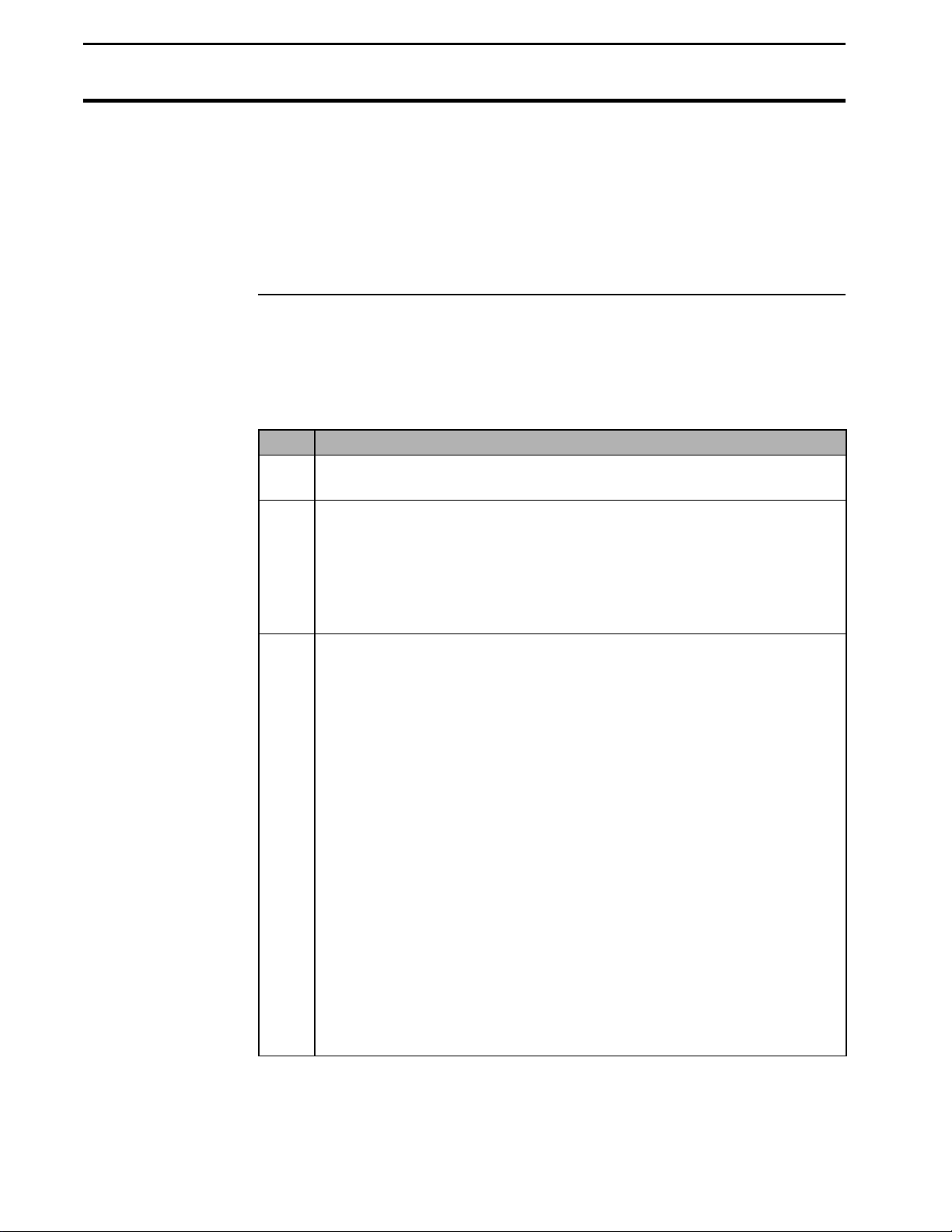
Clearing Field/Loads From
Memory
Notes:
• Even though you may have collected some data with incorrect monitor
settings, do not clear out actual harvest data. Many times, it is
possible to correct bad data by correcting settings or calibrations later.
• Clearing a load does not eliminate it. It only zeros the load’s data.
Yield Monitor 2000
Ag Leader Technology
Clearing All Fields
in the Monitor
Follow these procedures to eliminate all the fields and loads in the monitor.
Note: Normally, you will clear the monitor only when you are preparing to
begin a new harvest season.
Step Action
1 Press the MEM key until “CLEAR ALL FIELDS?” appears on the
display.
2 Press the YES key. The monitor beeps four times quickly and “ARE
YOU REALLY SURE?, YOU WILL LOSE DATA!” appears on the
display. Press the YES key.
Note: If you have changed your mind about clearing the monitor,
press any key other than the YES key.
3 “KEEP CAL LOADS?” appears on the display.
• Press the YES key if you want to keep all the calibration loads so
you can use the current calibration for the next harvest season.
• Press the NO key to also delete the calibration loads.
Note: If you are satisfied with the current grain weight calibration,
keep the calibration loads. If you keep the calibration loads, you can
use your old calibration loads next year’s calibration. You still may
have to enter a few new calibration loads depending on if your old
calibration was done over a wide range of grain flow rates.
4-32
If you plan to replace the clean grain elevator chain before the next
harvest season or you are going to adjust the top shaft, you should
not keep the old calibration loads.
Your old calibration loads will be in Field 0. The name of the field
will be CAL LOAD, and each load will be named with the original
field and load numbers.
June 1997
Page 99

Yield Monitor 2000
Ag Leader Technology
Step Action
4 “KEEP FIELD NAMES?” appears on the monitor display.
Clearing Fields/Loads From
Memory
• Press the YES key to keep all the existing fields and field names.
• Press the NO key to delete all the existing fields and field names.
Recommendation: If you want to delete the names of only some of
the existing fields, it will still save you time to keep all the field
names and use a computer or the monitor to delete the field names
you do not want to keep. To delete the field names on the monitor,
set each character of the field name to a space. The space character is
between the 9 and the A as you press the ARROW keys to scroll
through the list.
If you keep the field names, the monitor leaves one load in each field,
but erases the yield data for the field and all the loads in the field. The
monitor selects the following settings for every Load 1 in every field:
• Grain type remains the same
• Moisture is set to AUTO
• Speed remains the same
Go through each Load 1 in each field and set the grain type to
the crop you will harvest in that field next season after you have
erased all the loads but kept the field names. Also, make sure the
moisture and speed settings are correct for every Load 1.
5 The monitor beeps four times again and “REALLY WANT TO
ERASE FIELD DATA?” appears on the display. Press the YES key
to erase, otherwise press any key other than the YES key to bypass
erasing.
Notes:
• If you decide that you should not have cleared the monitor, you can
restore main memory from backup if you copied the main memory to the
backup memory before you cleared the monitor.
• Clearing the monitor does not change the distance, moisture,
temperature, or C1 calibration numbers.
* * *
June 1997
4-33
Page 100

Logging Map Data to a Card
Yield Monitor 2000
Ag Leader Technology
Important
Introduction
Never leave a memory card in the monitor when the monitor is shut off.
If you do so, it will drain the batteries of the monitor and your data will
become corrupt.
The yield monitor can read position information from a GPS receiver and
record data for yield mapping. To save GPS data, you must use a memory
card or datalogger. Refer to Important Notes below for more information on
Memory Cards.
Using a memory card to log yield map data has the advantage that all the
field, load, and calibration information from the monitor's memory is copied
to the card, which allows for later recalibration of the yield map data.
Example: If you wait until the third field you harvest before calibrating the
monitor, your GPS yield data for the first two fields will automatically be
recalibrated when you calibrate in the third field.
Note: This capability is only available when you log data to a memory card.
It is not available if you use a datalogger.
Important Notes
• You must copy memory data to a card before you read the memory
card into your computer. You must use Precision Map 2000 software
or other mapping software to download and archive data on a memory
card. When you copy data to the backup memory, the monitor
automatically copies the data to a card if the logging device (accessed by
pressing the SETUP key) is set to a card and the memory card is
installed in the monitor.
• If the message “COPY FAILED - TRY AGAIN” appears on the monitor
display when you are copying data to or restoring data from a card, you
probably have a bad card.
• If you install a card that has the write-protect switch on, the monitor
displays “MOVE SWITCH ON CARD”. Use the tip of a pen or pencil
to move the small switch on the outer end of the card.
4-34
June 1997
 Loading...