

Page 1

Agilent
N8201A Performance
Downconverter
Synthetic Instrument
Module, 3 Hz to 26.5 GHz
User’s Guide
Edition, January 22, 2008
N8201-90006
Agilent Technologies
Page 2

Notices
CAUTION
WARNING
© Agilent Technologies, Inc. 2006 - 2008
No part of this manual may be reproduced
in any form or by any means (including
electronic storage and retrieval or translation into a foreign language) without prior
agreement and written consent from Agilent Technologies, Inc. as governed by
United States and international copyright
laws.
Windows
Adobe Acrobat Reader
®
®
Manual Part Number
N8201-90006
Edition
Edition, January 22, 2008
Printed in USA
Agilent Technologies, Inc.
1400 Fountaingrove Pkwy
Santa Rosa, CA 95403
Warranty
The material contained in this document is provided “as is,” and is subject to being changed, without notice,
in future editions. Further, to the maximum extent permitted by applicable
law, Agilent disclaims all warranties,
either express or implied, with regard
to this manual and any information
contained herein, including but not
limited to the implied warranties of
merchantability and fitness for a particular purpose. Agilent shall not be
liable for errors or for incidental or
consequential damages in connection
with the furnishing, use, or performance of this document or of any
information contained herein. Should
Agilent and the user have a separate
written agreement with warranty
terms covering the material in this
document that conflict with these
terms, the warranty terms in the separate agreement shall control.
Technology Licenses
The hardware and/or software described in
this document are furnished under a
license and may be used or copied only in
accordance with the terms of such license.
Restricted Rights Legend
computer software” as defined in FAR
52.227-19 (June 1987) or any equivalent
agency regulation or contract clause. Use,
duplication or disclosure of Software is
subject to Agilent Technologies’ standard
commercial license terms, and non-DOD
Departments and Agencies of the U.S. Government will receive no greater than
Restricted Rights as defined in FAR
52.227-19(c)(1-2) (June 1987). U.S. Government users will receive no greater than
Limited Rights as defined in FAR 52.227-14
(June 1987) or DFAR 252.227-7015 (b)(2)
(November 1995), as applicable in any
technical data.
Safety Notices
A CAUTION notice denotes a hazard. It calls attention to an operating procedure, practice, or the like
that, if not correctly performed or
adhered to, could result in damage
to the product or loss of important
data. Do not proceed beyond a
CAUTION notice until the indicated
conditions are fully understood and
met.
A WARNING notice denotes a
hazard. It calls attention to an
operating procedure, practice, or
the like that, if not correctly performed or adhered to, could result
in personal injury or death. Do not
proceed beyond a WARNING
notice until the indicated conditions are fully understood and met.
If software is for use in the performance of
a U.S. Government prime contract or subcontract, Software is delivered and
licensed as “Commercial computer software” as defined in DFAR 252.227-7014
(June 1995), or as a “commercial item” as
defined in FAR 2.101(a) or as “Restricted
Page 3

Introducing the N8201A Performance Downconverter
The Agilent Technologies N8201A performance downconverter down converts a microwave
signal to an IF signal providing IF output frequencies of 7.5, 21.4, and 321.4 MHz to offer
three different signal bandwidth capabilities. External mixing can be utilized to down
convert microwave signals up to 110 GHz. The N8201A is based upon the industry’s most
accurate spectrum analyzer, the PSA Series.
Agilent's synthetic instrument family offers the highest-performing RF/MW LAN-based
modular instrumentation and the smallest footprint for automated test systems; providing
the maximum flexibility and minimizing the cost of an ATS over its lifetime.
Agilent’s synthetic instrument modules use LAN eXtension for Instrumentation (LXI)
modular format. LXI differs from other modular formats (such as VXI and PXI) by using an
external computer and local area network (LAN), rather than embedded computers, for
control.
The LXI standard supports the IEEE 1588 time synchronization and protocol standard, which
allows synchronous triggering of different instruments, even with different-length LAN
cables. The IEEE 1588 precision time protocol (PTP) enables a common sense of time over a
distributed system.
Synthetic instrument modules offered by Agilent Technologies include the following:
• N8201A performance downconverter, 3 Hz to 26.5 GHz
• N8211A performance analog upconverter, 250 kHz to 20 / 40 GHz
• N8212A performance vector upconverter, 250 kHz to 20 GHz
• N8221A IF digitizer, 30 MS/s
• N8241A arbitrary waveform generator, 15-Bit, 1.25 GS/s or 625 MS/s
• N8242A arbitrary waveform generator, 10-Bit, 1.25 GS/s or 625 MS/s
For further information, refer to:
http://www.agilent.com/find/synthetic
Agilent N8201A Performance Downconverter Synthetic Instrument Module, 3 Hz to 26.5 GHz 3
Page 4

4 Agilent N8201A Performance Downconverter Synthetic Instrument Module, 3 Hz to 26.5 GHz
Page 5

Contents
1 Software Installation
2 Hardware Setup and Configuration
Introducing the N8201A Performance Downconverter 3
Installing Software and Instrument Drivers 6
Step 1. Install Microsoft .NET Version 1.1 7
Step 2. Install the Agilent I/O Libraries 8
Step 3. Install the IVI Shared Components 9
Step 4. Install the Agilent Synthetic Instrument Finder 11
Step 5. Install the Agilent Synthetic Instrument GUI 12
Step 6. Install the IVI-COM Drivers 13
Step 7. Install the Agilent N8201A Performance Downconverter User Interface 15
Installing Optional Software and Instrument Drivers 16
(Optional) Step 8. Install the Agilent N8201A Option H02 Spectrum Analyzer GUI 17
(Optional) Step 9. Install the Microsoft Virtual Machine (VM) 19
(Optional) Step 10. Install the Apache HTTP Server 21
(Optional) Step 11. Install the SA Remote Web Server 24
Step 1. Unpack the N8201A Performance Downconverter 28
Verify the Shipment 28
(Optional) Prepare the Instrument for Rack Mounting 28
Step 2. Connect LAN Cables and Turn On Power 29
(Optional) Connect to a LAN with a Cross-Over LAN Cable 31
Step 3. Verify Connection with Synthetic Instrument Finder 32
(Optional) Step 4. Connect to the Agilent N8201A Option H02 Spectrum Analyzer GUI 34
(Optional) Step 5. Connect to an SA Remote Web Server 36
(Optional) Step 6. Verify Operation < 3 GHz 43
Performing a Self-Test 43
(Optional) Step 7. Verify Operation > 3 GHz 47
Performing a Self-Test 47
Troubleshooting 50
Alternative Ways to Verify Connectivity to the PC 50
How to Use the Synthetic Instrument Finder 51
How to Reset the LAN Configuration 55
How to Set a Static IP Address 56
How to Troubleshoot Connectivity Problems on the Network 60
Agilent N8201A Performance Downconverter Synthetic Instrument Module, 3 Hz to 26.5 GHz 1
Page 6

How to Determine a PCs Configuration Settings 60
If the Instrument was Unable to Join the LAN 62
If the LAN LED is Red 62
If the Instrument’s IP Address or Hostname Cannot be Found with Ping 63
If the Instrument is Not Found by the Synthetic Instrument Finder 63
If the Instrument’s Hostname and PC Cannot Communicate 63
If the Instrument Web Page is Not Visible 64
If the Software Driver Will Not Open the Connection 64
3 Using the Agilent Synthetic Instrument GUI
Starting the Agilent Synthetic Instrument GUI 67
Left Pane 68
Right Pane 68
Features of the Agilent Synthetic Instrument GUI 69
File Menu 69
Help 70
Left Pane 71
Right Pane 72
Settings on the Agilent Synthetic Instrument GUI 74
Frequency 74
Frequency List 74
Level 76
Input RF 76
IF Output 76
Reference Oscillator 76
Preselector (Option 123) 77
External Mixer 77
Calibration 78
Events (Settling Events and Event Logging) 78
Event Logging 79
Preset 80
Refresh All Values 80
4 Front and Rear Panel Features
N8201A Performance Downconverter Front Panel Features 82
RF INPUT 82
Power 82
Line Power LED 83
LAN LED 83
1588 LED 84
2 Agilent N8201A Performance Downconverter Synthetic Instrument Module, 3 Hz to 26.5 GHz
Page 7

COHERENT CARRIERS 84
EXT MIXER 85
IF OUTPUTS 85
TRIGGERS 85
REFERENCES 85
IF LOG VIDEO (Option V7L) 86
NOISE SOURCE +28 V (PULSED) (Option 219) 86
VGA OUT 86
N8201A Performance Downconverter Rear Panel Features 87
AC Power Receptacle 87
LAN 87
LXI Trigger Bus 88
Interconnect Cabling 89
Operational Considerations 90
Agilent 89601A Vector Signal Analysis Software 90
Configuring the Local Area Network (LAN) Interface 90
5 Preventive Maintenance
Using, Inspecting, and Cleaning RF Connectors 92
Repeatability 92
RF Cable and Connector Care 92
Proper Connector Torque 93
Connector Wear and Damage 93
SMA Connector Precautions 93
Cleaning Procedure 94
General Procedures and Techniques 95
Connector Removal 96
Instrument Removal 98
Standard instrument 98
Half-Rack-Width Instrument 99
Bench Top Instrument 99
Instrument Installation 100
Standard rack instrument 100
Half-Rack-Width Instrument 101
Bench Top Instrument 101
6 Service, Support, and Safety Information
Safety and Regulatory Information 104
EMC 104
Agilent N8201A Performance Downconverter Synthetic Instrument Module, 3 Hz to 26.5 GHz 3
Page 8

7Glossary
Safety 104
Safety Summary 104
Equipment Installation 105
Environmental Conditions 106
Before Applying Power 106
Magnetic Susceptibility 107
Vibration 107
Ground the Instrument or System 107
Fuses and Circuit Breakers 108
Maintenance 108
Safety symbols and Instrument Markings 108
Service and Support 111
Agilent on the Web 111
Return Procedure 112
Shipping the Instrument 112
4 Agilent N8201A Performance Downconverter Synthetic Instrument Module, 3 Hz to 26.5 GHz
Page 9

User’s Guide
1
Software Installation
This installation process installs the required software and instrument drivers used by the
N8201A performance downconverter:
“Verify the PC Meets Minimum Requirements" on page 6
“Step 1. Install Microsoft .NET Version 1.1" on page 7
“Step 2. Install the Agilent I/O Libraries" on page 8
“Step 3. Install the IVI Shared Components" on page 9
“Step 4. Install the Agilent Synthetic Instrument Finder" on page 11
“Step 5. Install the Agilent Synthetic Instrument GUI" on page 12
“Step 6. Install the IVI-COM Drivers" on page 13
“Step 7. Install the Agilent N8201A Performance Downconverter
User Interface" on page 15
Install the following only if the N8201A performance downconverter has Option H02
“(Optional) Step 8. Install the Agilent N8201A Option H02
Spectrum Analyzer GUI" on page 17
Install the following only if the N8201A performance downconverter has Option H02
(Optional Steps 9, 10, and 11 are available to support legacy installations and are not
required if the software from Step 8 is being used. This interface can be installed
along with the Agilent N8201A Option H02 Spectrum Analyzer GUI, but only one
interface can be used at any given time.)
“(Optional) Step 9. Install the Microsoft Virtual Machine (VM)" on page 19
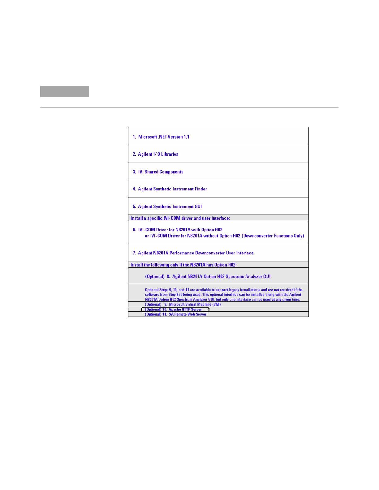
“(Optional) Step 10. Install the Apache HTTP Server" on page 21
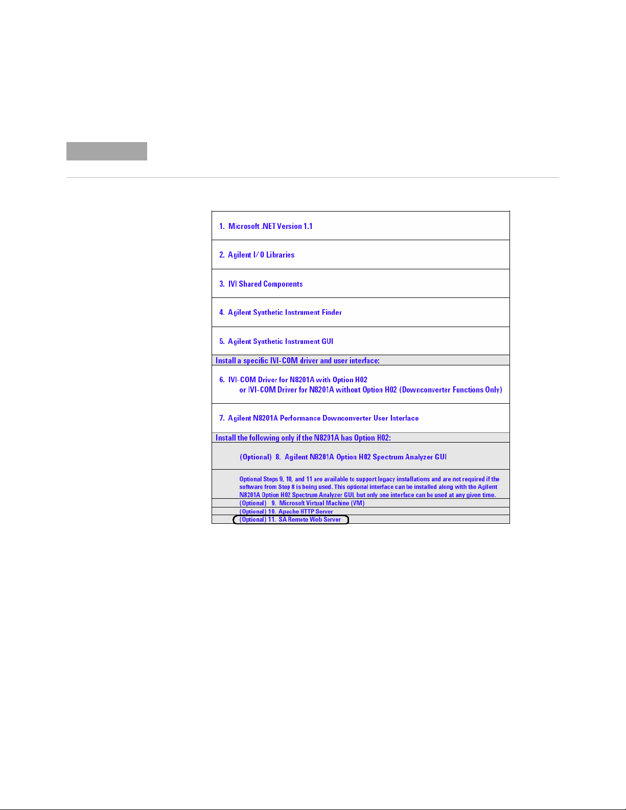
“(Optional) Step 11. Install the SA Remote Web Server" on page 24
Agilent Technologies
5
Page 10

1 Software Installation
NOTE
CAUTION
Installing Software and Instrument Drivers
1 Verify the PC Meets Minimum Requirements
• 1 GHz Intel Pentium processor
• Microsoft Windows XP Professional or Home Edition (Service Pack 1
or 2), Windows 2000 (Service Pack 2)
• 512 MB of RAM
• Up to 40 MB of available hard- disk space
• Microsoft Internet Explorer 6.0 (or higher), or Netscape 7.1 or 8.0
2 Place the CD with the Instrument Drivers and Documentation in the CD-ROM drive.
a Adobe Acrobat Reader 5.0 or later is used during this installation process and can be
installed from the CD described above.
b Click Adobe Acrobat Reader 5.0 to install the software, if needed.
3 Click Instrument Drivers.
If the following software or instrument drivers are installed on the PC to be used, uninstall
them and install the software and instrument drivers shipped on the CD described above:
Step 1. Microsoft .NET 1.1
Step 2. Agilent I/O Libraries
Step 3. IVI Shared Components
Step 4. Agilent Synthetic Instrument Finder
Step 5. Agilent Synthetic Instrument GUI
Step 6. IVI-COM Drivers (for N8201A with Option H02 and without Option H02)
Step 7. Agilent N8201A Performance Downconverter User Interface
(Optional) Install the following only if the downconverter has Option H02
Step 8. Agilent N8201A Option H02 Spectrum Analyzer GUI
(Optional) Steps 9, 10, and 11 are available to support legacy installations and are not
required if the software from Step 8 is being used. This interface can be installed along with
the Agilent N8201A Option H02 Spectrum Analyzer GUI, but only one interface can be used
at any given time.
Step 9. Microsoft Virtual Machine (VM)
Step 10. Apache HTTP Server
Step 11. SA Remote Web Server
6 Agilent N8201A Performance Downconverter Synthetic Instrument Module, 3 Hz to 26.5 GHz
Page 11
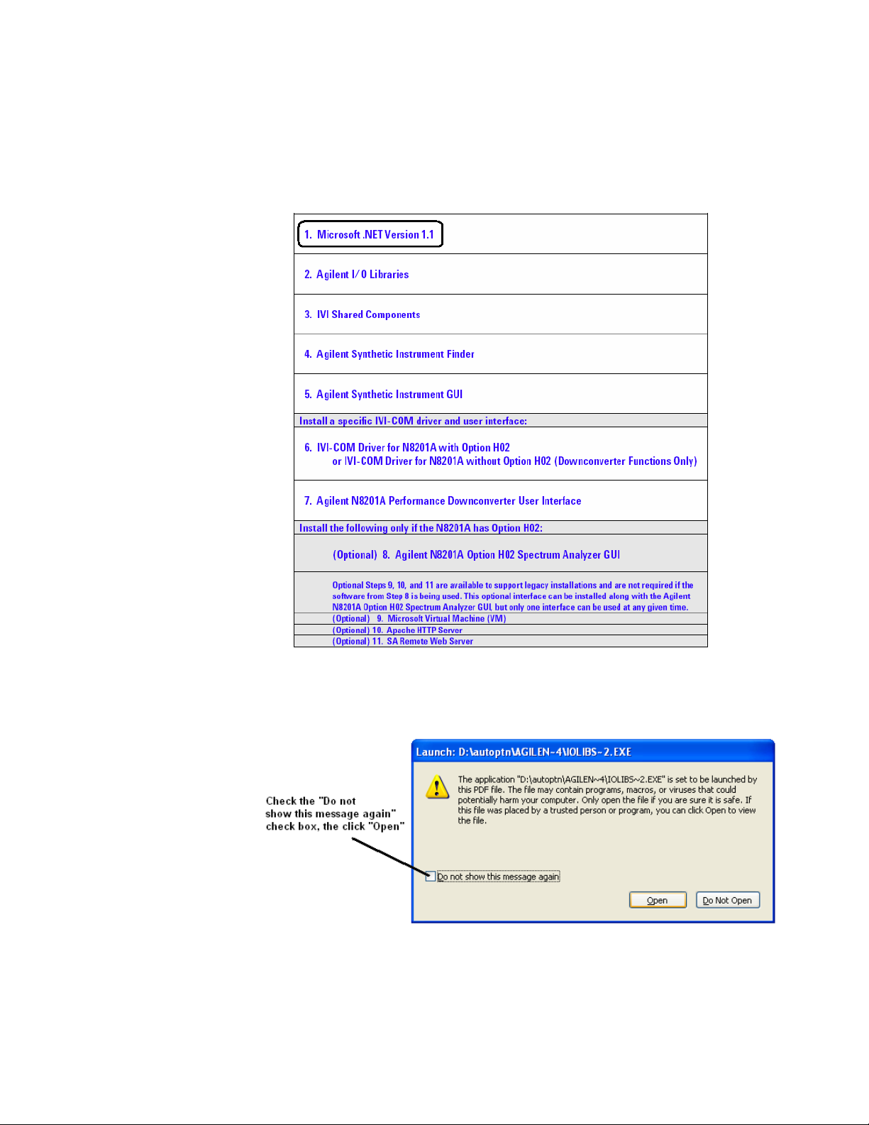
Step 1. Install Microsoft .NET Version 1.1
1 Select Microsoft Version 1.1.
Software Installation 1
2 Click the check box, “Do not show this message again” so that the check box is
selected. This will stop the message from displaying each time a selection is made from
the Software and Driver Installation menu.
3 Click Open.
4 Follow the installation instructions and accept the default settings.
5 Click Finish.
Agilent N8201A Performance Downconverter Synthetic Instrument Module, 3 Hz to 26.5 GHz 7
Page 12

1 Software Installation
Step 2. Install the Agilent I/O Libraries
1 Select Agilent I/O Libraries.
2 Follow the instructions and accept the default settings.
3 Click Finish.
8 Agilent N8201A Performance Downconverter Synthetic Instrument Module, 3 Hz to 26.5 GHz
Page 13
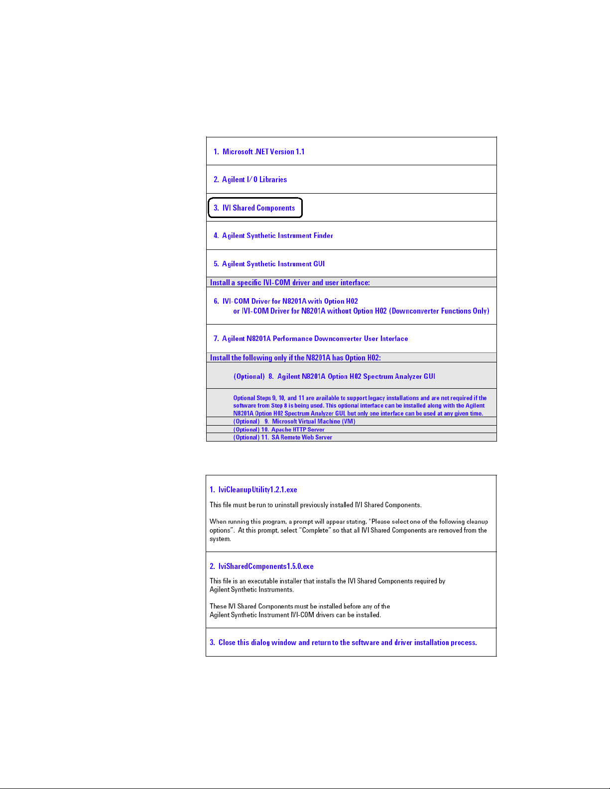
Step 3. Install the IVI Shared Components
1 Select IVI Shared Components.
Software Installation 1
2 Run the IviCleanupUtility before running the IviSharedComponents or a network access
error may occur during installation of the IviSharedComponents.
Agilent N8201A Performance Downconverter Synthetic Instrument Module, 3 Hz to 26.5 GHz 9
Page 14
1 Software Installation
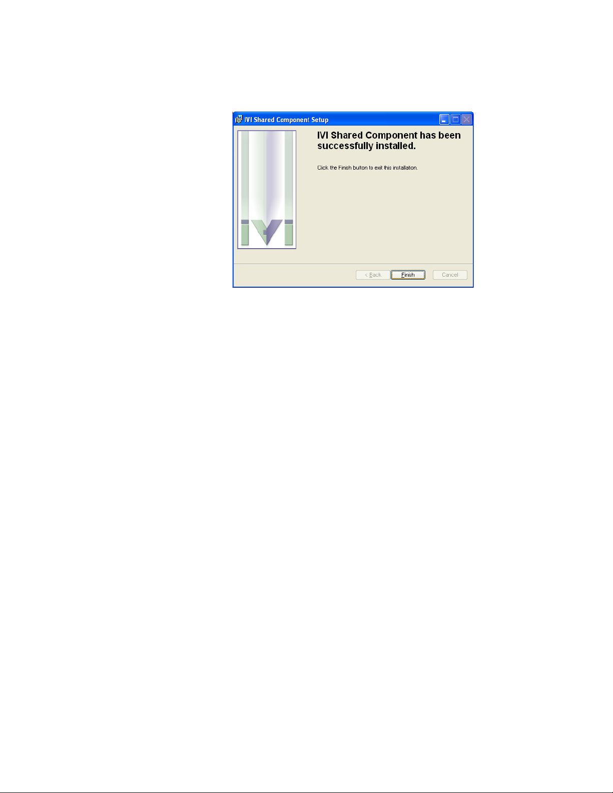
3
4 Click Finish.
Follow the installation instructions and accept the default settings.
10 Agilent N8201A Performance Downconverter Synthetic Instrument Module, 3 Hz to 26.5 GHz
Page 15
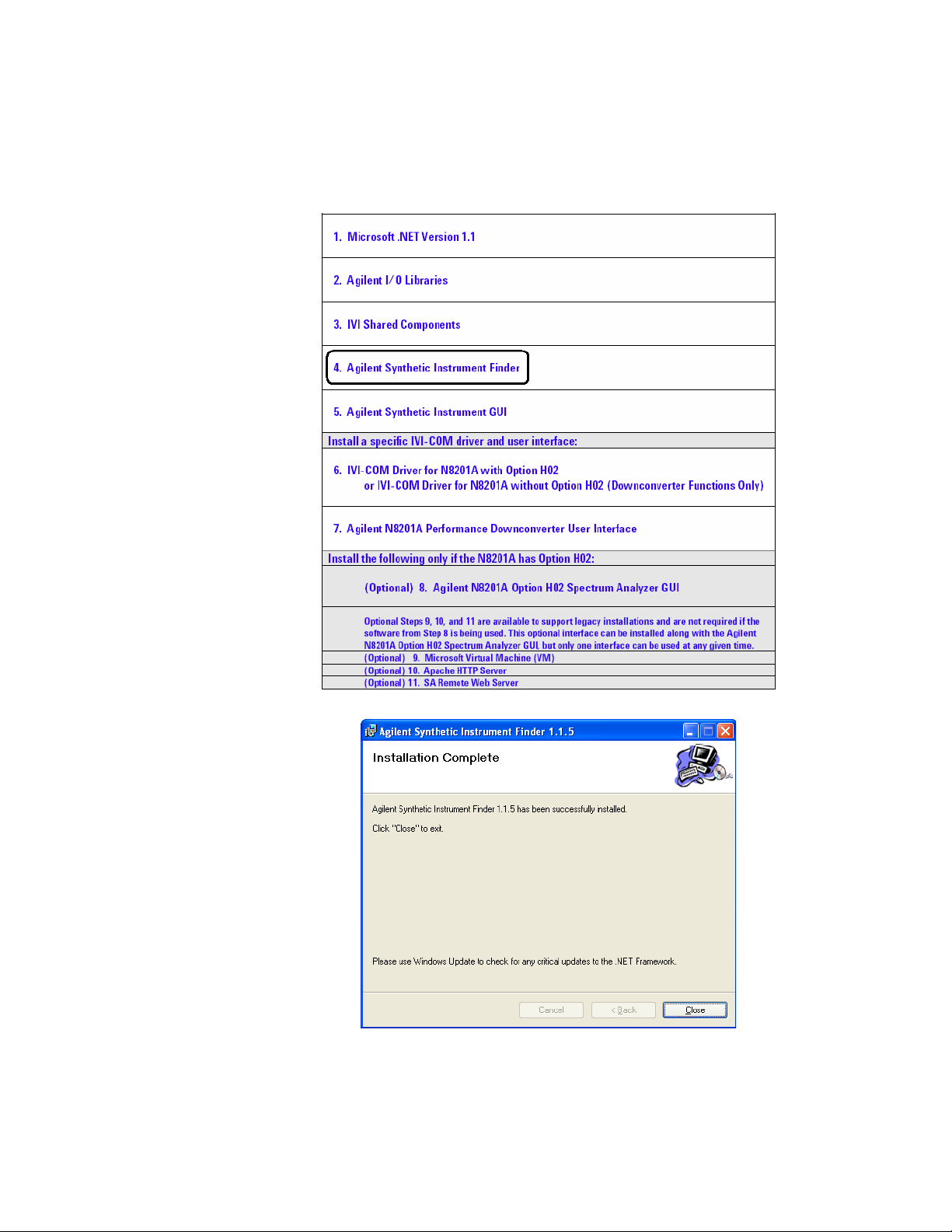
Step 4. Install the Agilent Synthetic Instrument Finder
1 Select Agilent Synthetic Instrument Finder.
Software Installation 1
2 Follow the installation instructions and accept the default settings.
3 Click Close.
Agilent N8201A Performance Downconverter Synthetic Instrument Module, 3 Hz to 26.5 GHz 11
Page 16

1 Software Installation
Step 5. Install the Agilent Synthetic Instrument GUI
1 Select Agilent Synthetic Instrument GUI.
2 Follow the installation instructions and accept the default settings.
Click Close.
12 Agilent N8201A Performance Downconverter Synthetic Instrument Module, 3 Hz to 26.5 GHz
Page 17
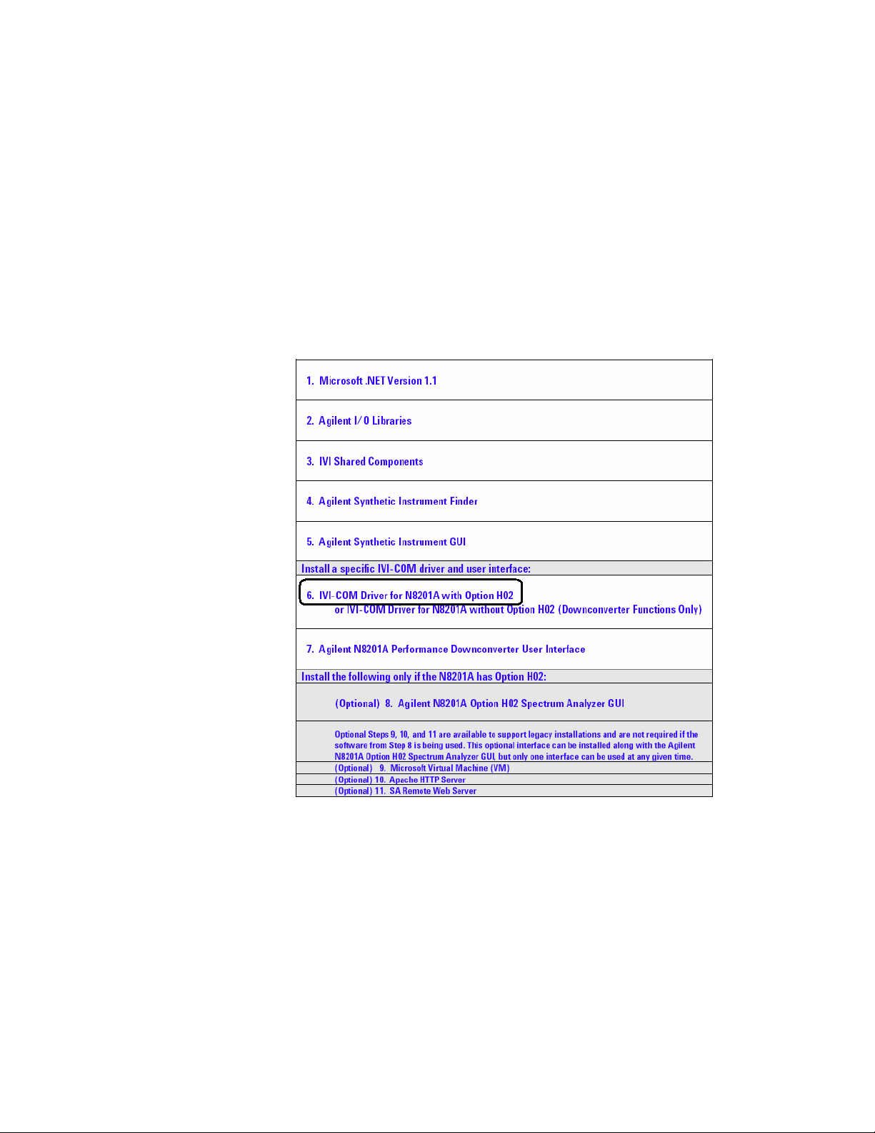
Step 6. Install the IVI-COM Drivers
There are two different IVI-COM drivers available for the N8201A performance
downconverter.
• If the N8201A performance downconverter is equipped with Option H02, a different
IVI-COM driver is available that enables functionality similar to a PSA spectrum analyzer.
• If the N8201A performance downconverter is not equipped with Option H02, only
downconverter functions are available.
1 Select one of the IVI-COM Drivers.
Software Installation 1
Agilent N8201A Performance Downconverter Synthetic Instrument Module, 3 Hz to 26.5 GHz 13
Page 18

1 Software Installation
2
You should see the above dialog when the installation is complete for IVI-COM that
supports Option H02 and the below dialog when the installation is complete for IVI-COM
that supports N8201A performance downconverters that are not equipped with Option H02.
Follow the installation instructions and accept the default settings.
3 Click Finish.
14 Agilent N8201A Performance Downconverter Synthetic Instrument Module, 3 Hz to 26.5 GHz
Page 19

Software Installation 1
Step 7. Install the Agilent N8201A Performance Downconverter User Interface
1 Select Agilent N8201A Performance Downconverter User Interface.
2 Follow the installation instructions and accept the default settings.
3 Click Close.
Agilent N8201A Performance Downconverter Synthetic Instrument Module, 3 Hz to 26.5 GHz 15
Page 20

1 Software Installation
Installing Optional Software and Instrument Drivers
Software for steps 8, 9, 10, and 11 can be installed on your PC, but Option H02 is required to
use these software applications with the N8201A performance downconverter; prior to
continuing, verify that Option H02 is installed.
To Verify that Option H02 is Installed
1 Start the Synthetic Instrument Finder (from the Windows Desktop,
click Start > All Programs > Agilent SI Tools > Synthetic Instrument Finder).
2 Select an instrument, from the left-hand pane of the Synthetic Instrument Finder, and
right-click on the instrument with the mouse.
3 Select Interactive IO.
4 Type *OPT? at the Command prompt and click Send & Read.
5 Read the response in the Instrument Session History box; the required option should be
listed as H02.
If Option H02 is Installed
• If Option H02 is installed, proceed to “(Optional) Step 8. Install the Agilent N8201A
Option H02 Spectrum Analyzer GUI" on page 17.
• If Option H02 is installed, you can also use the SA Remote Web Server. To use this
optional interface, you must perform “(Optional) Step 9. Install the Microsoft Virtual
Machine (VM)" on page 19, “(Optional) Step 10. Install the Apache HTTP Server" on
page 21, and “(Optional) Step 11. Install the SA Remote Web Server" on page 24; this
interface can be installed along with the Agilent N8201A Option H02 Spectrum Analyzer
GUI, but only one interface can be used at any given time.
If Option H02 is Not Installed
• If Option H02 is not installed, software installation is complete!
The N8201A performance downconverter can be manually controlled on instruments
without Option H02 by using the Agilent Synthetic Instrument GUI.
(Refer to “Starting the Agilent Synthetic Instrument GUI" on page 67.)
• Without Option H02, the Agilent N8201A Option H02 Spectrum Analyzer GUI cannot
be used and does not need the software installed.
• Without Option H02, the N8201A performance downconverter cannot be used with
the SA Remote Web Server and does not need software installed for the Microsoft
Virtual Machine (VM), the Apache HTTP Server, or the SA Remote Web Server.
a Close the Interactive IO dialog box.
b Close the Synthetic Instrument Finder dialog box.
c Click Exit CD-ROM. The software and driver installation is complete!
d Restart the computer and continue to “Hardware Setup and Configuration" on
page 27.
16 Agilent N8201A Performance Downconverter Synthetic Instrument Module, 3 Hz to 26.5 GHz
Page 21
Software Installation 1
NOTE
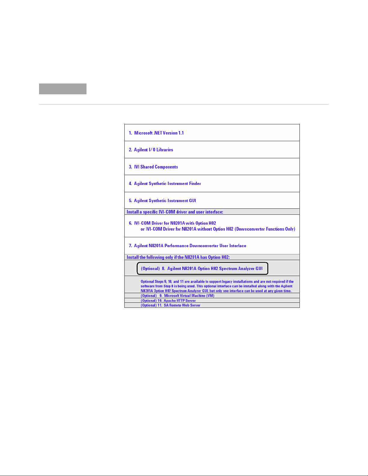
(Optional) Step 8. Install the Agilent N8201A Option H02 Spectrum Analyzer GUI
Before performing this optional installation step, read about
“Installing Optional Software and Instrument Drivers" on page 16.
1 Select Agilent N8201A Option H02 Spectrum Analyzer GUI.
Agilent N8201A Performance Downconverter Synthetic Instrument Module, 3 Hz to 26.5 GHz 17
Page 22
1 Software Installation
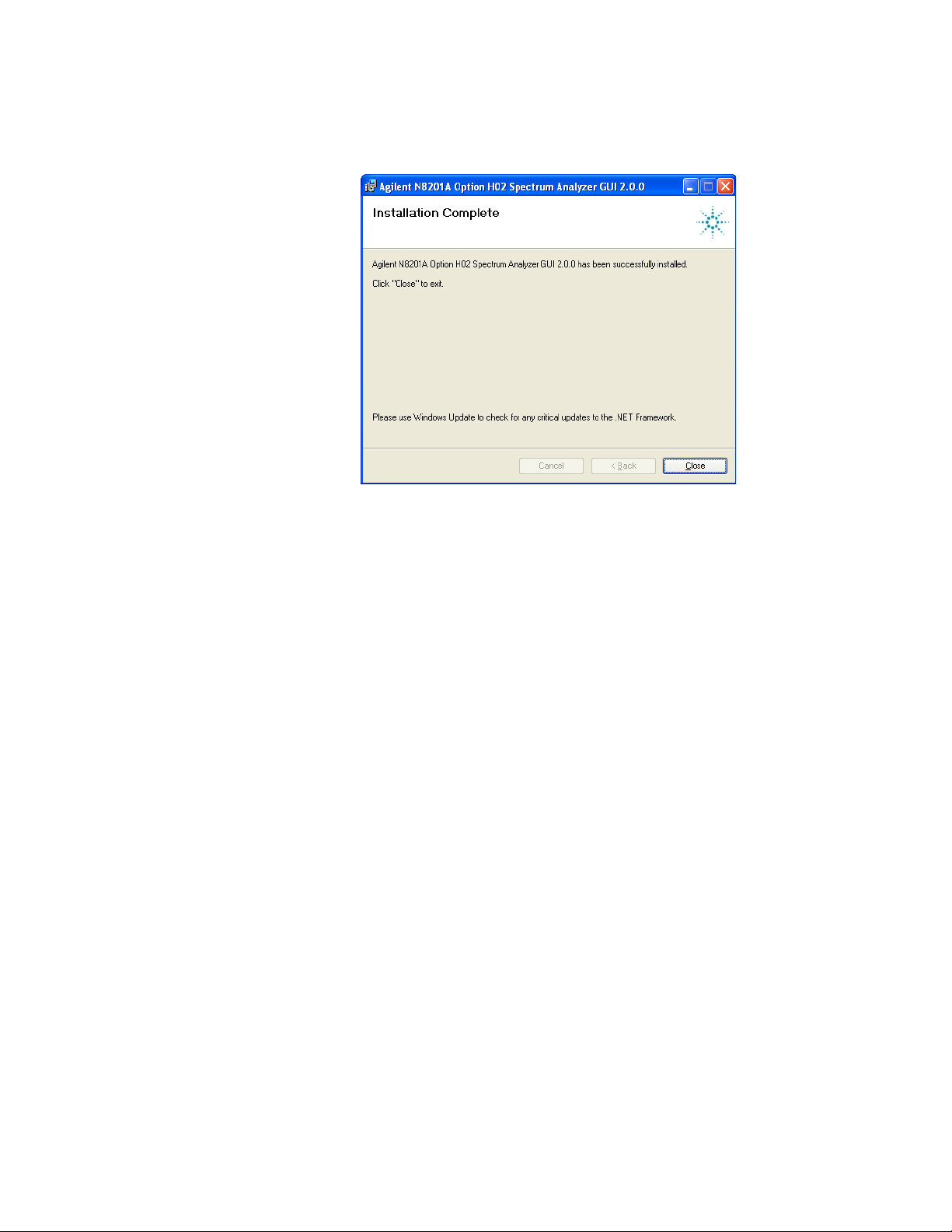
2
3 Click Close.
Follow the installation instructions and accept the default settings.
18 Agilent N8201A Performance Downconverter Synthetic Instrument Module, 3 Hz to 26.5 GHz
Page 23
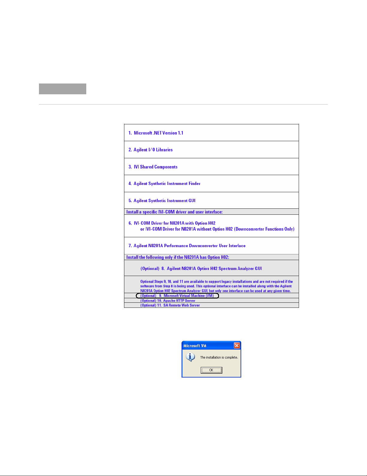
(Optional) Step 9. Install the Microsoft Virtual Machine (VM)
NOTE
Before performing this optional installation step, read about
“Installing Optional Software and Instrument Drivers" on page 16.
1 Select Microsoft Virtual Machine (VM).
Software Installation 1
2 Follow the installation instructions and accept the default settings.
3 Click OK.
Agilent N8201A Performance Downconverter Synthetic Instrument Module, 3 Hz to 26.5 GHz 19
Page 24

1 Software Installation
4
Click No on the Microsoft VM dialog box. This step will be completed later in the
process after the SA Remote Web Server is installed.
20 Agilent N8201A Performance Downconverter Synthetic Instrument Module, 3 Hz to 26.5 GHz
Page 25
(Optional) Step 10. Install the Apache HTTP Server
NOTE
Before performing this optional installation step, read about
“Installing Optional Software and Instrument Drivers" on page 16.
1 Select Apache HTTP Server.
Software Installation 1
Agilent N8201A Performance Downconverter Synthetic Instrument Module, 3 Hz to 26.5 GHz 21
Page 26

1 Software Installation
2
3 Click Next.
Follow the installation instructions and accept the default settings
4 Click Next.
22 Agilent N8201A Performance Downconverter Synthetic Instrument Module, 3 Hz to 26.5 GHz
Page 27
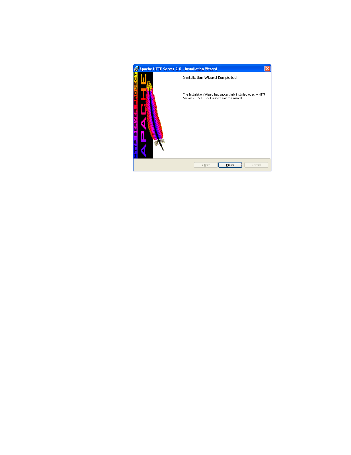
Click Finish.
5
Software Installation 1
Agilent N8201A Performance Downconverter Synthetic Instrument Module, 3 Hz to 26.5 GHz 23
Page 28
1 Software Installation
NOTE
(Optional) Step 11. Install the SA Remote Web Server
Before performing this optional installation step, read about
“Installing Optional Software and Instrument Drivers" on page 16.
1 Select SA Remote Web Server.
24 Agilent N8201A Performance Downconverter Synthetic Instrument Module, 3 Hz to 26.5 GHz
Page 29
Software Installation 1
NOTE
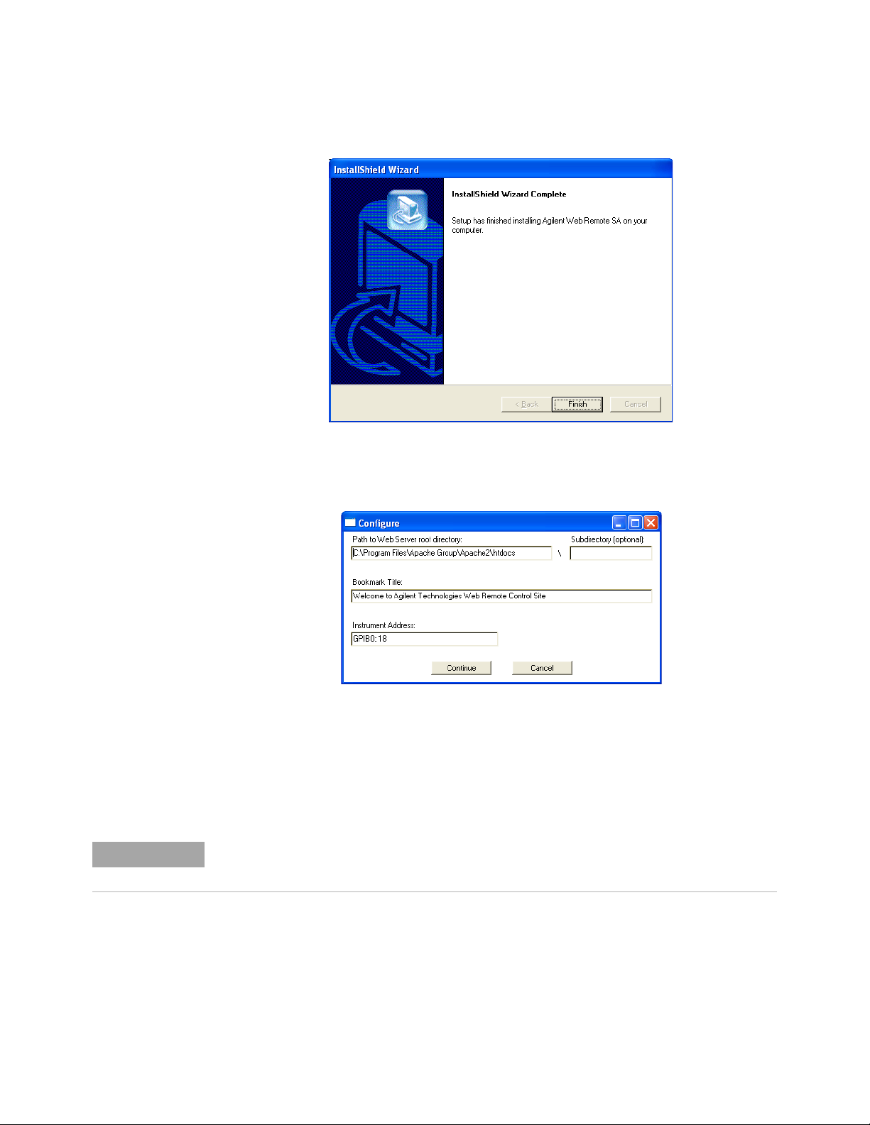
Follow the installation instructions and accept the default settings.
2
3 Click Finish.
4 Click Cancel on the Configure dialog box. This step will be completed later in the
process after restarting the computer.
5 Close the Agilent N8201A Performance Downconverter Software and Driver Installation
menu (driver_installation_list.pdf dialog box).
6 Click Exit CD-ROM. The software and driver installation is complete.
7 Restart the computer and continue to “Hardware Setup and Configuration" on page 27.
Restart the computer!
Agilent N8201A Performance Downconverter Synthetic Instrument Module, 3 Hz to 26.5 GHz 25
Page 30

1 Software Installation
26 Agilent N8201A Performance Downconverter Synthetic Instrument Module, 3 Hz to 26.5 GHz
Page 31

User’s Guide
2
Hardware Setup and Configuration
“Step 1. Unpack the N8201A Performance Downconverter" on page 28
“Step 2. Connect LAN Cables and Turn On Power" on page 29
“Step 3. Verify Connection with Synthetic Instrument Finder" on page 32
“(Optional) Step 4. Connect to the Agilent N8201A Option H02
Spectrum Analyzer GUI" on page 34
“(Optional) Step 5. Connect to an SA Remote Web Server" on page 36
“(Optional) Step 6. Verify Operation < 3 GHz" on page 43
“(Optional) Step 7. Verify Operation > 3 GHz" on page 47
“Troubleshooting" on page 50
• “Alternative Ways to Verify Connectivity to the PC" on page 50
• “How to Reset the LAN Configuration" on page 55
• “How to Set a Static IP Address" on page 56
• “How to Troubleshoot Connectivity Problems on the Network" on page 60
• “How to Determine a PCs Configuration Settings" on page 60
• “If the Instrument was Unable to Join the LAN" on page 62
• “If the LAN LED is Red" on page 62”
• “If the Instrument’s IP Address or Hostname Cannot be Found with Ping" on page 63
• “If the Instrument is Not Found by the Synthetic Instrument Finder" on page 63”
• “If the Instrument’s Hostname and PC Cannot Communicate" on page 63”
• “If the Instrument Web Page is Not Visible" on page 64”
• “If the Software Driver Will Not Open the Connection" on page 64”
Agilent Technologies
27
Page 32

2 Hardware Setup and Configuration
WARNING
NOTE
CAUTION
Step 1. Unpack the N8201A Performance Downconverter
The unique shape of the N8201A performance downconverter was intended to allow
multiple instruments to reside in a compact system that is both modular and
transportable. With instruments adjacent to each other, handles could not be installed on
the respective instruments. Exercise caution when lifting and carrying the instrument to
avoid personal injury. At 25.9 kilograms (57 pounds) shipping weight and 19 kilograms
(42 pounds) net weight, it is recommended that two people be utilized for instrument
lifting and transport.
Verify that any options ordered are included with the shipment by checking the packing
literature included with the shipment.
The serial number label on the N8201A performance downconverter only verifies
hardware/firmware options. The packing literature verifies all items shipped.
Verify the Shipment
1 Inspect the shipping container for damage.
Signs of damage may include a dented or torn shipping container or cushioning material
that shows signs of unusual stress or compacting.
2 Carefully remove the contents from the shipping container and verify that the order is
complete.
The following items are shipped standard with each N8201A performance
downconverter:
• instrument drivers, synthetic graphical user interface, and documentation CD-ROM
(p/n N8200-90004)
• three-prong AC power cord specific to geographic location
(Optional) Prepare the Instrument for Rack Mounting
If the N8201A performance downconverter is to be placed in a system rack, the feet
currently attached can be replaced with the rack mount feet (part number
W1312-40032) supplied with the accessories. Failure to do so can result in a safety
issue. For further information, refer to the Agilent N8200A Series Synthetic
Instrument Modules, Rack Configuration Guide, N8200-90003.
28 Agilent N8201A Performance Downconverter Synthetic Instrument Module, 3 Hz to 26.5 GHz
Page 33

Step 2. Connect LAN Cables and Turn On Power
NOTE
Install the N8201A performance downconverter so that the detachable power cord is
readily identifiable and is easily reached by the operator. The detachable power cord is the
instrument disconnecting device. It disconnects the mains circuits from the mains supply
before other parts of the instrument. The front panel switch is only a standby switch and is
not a LINE switch. Alternatively, an externally installed switch or circuit breaker (which is
readily identifiable and is easily reached by the operator) may be used as a disconnecting
device.
Before connecting to a LAN, verify your local policy by contacting the system administrator
in your Information Technology (IT) department and inquire about connecting instruments
to the LAN.
Hardware Setup and Configuration 2
• If the network uses DHCP [
assigned to the device automatically. If you need to know what the IP address is, it can
be determined using the Synthetic Instrument Finder. (Refer to “Step 3. Verify
Connection with Synthetic Instrument Finder" on page 32.)
• If DHCP is not present, but the instrument is set to use DHCP (the default), the
instrument waits two minutes for its DHCP request to time out. When the
N8201A performance downconverter is used in this situation, there is a time delay of
approximately three minutes between the time of when the N8201A performance
downconverter’s power is turned on and when it is available for use.
• If the network does not use DHCP, you can use Auto IP or configure your LAN
settings manually. Although you can also manually configure LAN settings in a
network with DHCP, it is recommended that you do so with the assistance of your
system administrator.
• If the network uses Auto IP (does not use DHCP), the N8201A performance
downconverter acquires a 169.254.xxx.xxx address. (Refer to “How to Set a Static IP
Address" on page 56.)
If you wish to communicate directly between the N8201A performance downconverter and
your PC without the use of a LAN hub, you can connect directly to your PC. (Refer to
“(Optional) Connect to a LAN with a Cross-Over LAN Cable" on page 31.)
Dynamic Host Configuration Protocol], an address is
Agilent N8201A Performance Downconverter Synthetic Instrument Module, 3 Hz to 26.5 GHz 29
Page 34

2 Hardware Setup and Configuration
1
Connect a LAN cable from the LAN connector on your PC to an empty connector on your
internal local area network or LAN hub.
2 Connect a LAN cable from the LAN connector on the rear panel of the
N8201A performance downconverter to an empty connector on your internal local area
network or LAN hub.
3 Turn on power to the PC.
4 Turn on power to the N8201A performance downconverter and wait until the LAN LED
turns solid green or until you hear an attenuator click from within the
N8201A performance downconverter; this can take up to four minutes depending on
whether the instrument is using DHCP or Auto IP.
30 Agilent N8201A Performance Downconverter Synthetic Instrument Module, 3 Hz to 26.5 GHz
Page 35

Hardware Setup and Configuration 2
(Optional) Connect to a LAN with a Cross-Over LAN Cable
If you wish to communicate directly between the N8201A performance downconverter and
your PC without the use of a LAN hub, you can connect directly to your PC.
1 Connect a cross-over LAN cable from the LAN connector on your PC to the LAN
connector on the rear panel of the N8201A performance downconverter.
2 Turn on power to the PC.
3 Turn on power to the N8201A performance downconverter and wait until the LAN LED
turns solid green or until you hear an attenuator click from within the
N8201A performance downconverter; this can take up to four minutes depending on
whether the instrument is using DHCP or Auto IP.
Agilent N8201A Performance Downconverter Synthetic Instrument Module, 3 Hz to 26.5 GHz 31
Page 36

2 Hardware Setup and Configuration
Step 3. Verify Connection with Synthetic Instrument Finder
Agilent supplies a program named the Synthetic Instrument Finder that enables
connection between a PC and instruments that are connected on a LAN [Local Area
Network].
1 From the Windows Desktop,
click Start > All Programs > Agilent SI Tools > Synthetic Instrument Finder.
The Synthetic Instrument Finder should appear and look similar to the following.
2 Select an instrument, from the left-hand pane of the Synthetic Instrument Finder, and
right-click on an instrument with the mouse.
32 Agilent N8201A Performance Downconverter Synthetic Instrument Module, 3 Hz to 26.5 GHz
Page 37

Hardware Setup and Configuration 2
Select Open Webpage and a Web browser should appear that allows viewing and
3
modifying settings for instruments on the network.
• If this Web page does not open or you experience an error, refer to
“Troubleshooting" on page 50.
• If this Web page opens, you have verified connectivity and can continue
on to one of the following:
• With Option H02 not installed, refer to
“Using the Agilent Synthetic Instrument GUI" on page 65
• With Option H02 installed, refer to
“(Optional) Step 4. Connect to the Agilent N8201A Option H02 Spectrum Analyzer
GUI" on page 34
• With Option H02 installed, refer to
“(Optional) Step 5. Connect to an SA Remote Web Server" on page 36.
Agilent N8201A Performance Downconverter Synthetic Instrument Module, 3 Hz to 26.5 GHz 33
Page 38

2 Hardware Setup and Configuration
NOTE
(Optional) Step 4. Connect to the Agilent N8201A Option H02
Spectrum
Analyzer GUI
If Option H02 is not installed, the Agilent N8201A Option H02 Spectrum Analyzer GUI
software cannot be used!
In addition to Option H02, you must have performed “(Optional) Step 8. Install the Agilent
N8201A Option H02 Spectrum Analyzer GUI" on page 17; this interface can be installed
along with the SA Web Remote Server, but only one interface can be used at any given time.
(For further software installation information, refer to “Installing Optional Software and
Instrument Drivers" on page 16.)
The N8201A performance downconverter can be manually controlled on instruments
without Option H02 by using the Agilent Synthetic Instrument GUI.
(Refer to “Starting the Agilent Synthetic Instrument GUI" on page 67.)
34 Agilent N8201A Performance Downconverter Synthetic Instrument Module, 3 Hz to 26.5 GHz
Page 39

Hardware Setup and Configuration 2
This section describes how to access and use the Agilent N8201A Option H02
Spectrum Analyzer GUI.
1 From the Windows Desktop, click
Start > All Programs > Agilent SI Tools > N8201A Option H02 Spectrum Analyzer GUI.
2 Click File > Connect (upper-left corner)
on the Agilent N8201A Option H02 Spectrum Analyzer GUI.
3 Enter the VISA Address (for example, TCPIP0::141.121.87.18::inst0::instr) of the
instrument being connected to and click OK.
• If you don’t know the IP address of the instrument, that is used as part of the
VISA Address connection string, refer to the Default IP Address that is displayed
when verifying connection with the Synthetic Instrument Finder. (Refer to “Step 3.
Verify Connection with Synthetic Instrument Finder" on page 32.)
The Agilent N8201A Option H02 Spectrum Analyzer GUI controls the N8201A performance
downconverter that is equipped with Option H02 and simulates the functionality of an
Agilent PSA spectrum analyzer. To learn how to use the controls of this GUI interface, refer
to the PSA documentation.
PSA documentation is available from the Agilent N8201A Performance Downconverter
Synthetic Instrument Module, 3 Hz to 26.5 GHz, Instrument Drivers and Documentation CD
(refer to “Installing Software and Instrument Drivers" on page 6) or from the Web at:
http://www.agilent.com/find/psa
Agilent N8201A Performance Downconverter Synthetic Instrument Module, 3 Hz to 26.5 GHz 35
Page 40

2 Hardware Setup and Configuration
NOTE
(Optional) Step 5. Connect to an SA Remote Web Server
If Option H02 is not installed, the SA Remote Web Server software cannot be used!
In addition to Option H02, you must have installed the Microsoft Virtual Machine (VM), the
Apache HTTP Server, and the SA Remote Web Server software; this interface can be
installed along with the Agilent N8201A Option H02 Spectrum Analyzer GUI, but only one
interface can be used at any given time. (For further software installation information, refer
to “Installing Optional Software and Instrument Drivers" on page 16.)
The N8201A performance downconverter can be manually controlled on instruments
without Option H02 by using the Agilent Synthetic Instrument GUI.
(Refer to “Starting the Agilent Synthetic Instrument GUI" on page 67.)
1 From the Windows Desktop,
select Start > All Programs > Agilent I/O Libraries Suite > Agilent Connection Expert.
2 Click Add Interface.
36 Agilent N8201A Performance Downconverter Synthetic Instrument Module, 3 Hz to 26.5 GHz
Page 41

Select Remote GPIB (via E5810 or Remote IO Server).
IP Address
3
Hardware Setup and Configuration 2
4 Click Add.
5 Enter the N8201A performance downconverter’s IP address.
If you do not know the IP address, use the Synthetic Instrument Finder.
a From the Windows Desktop,
select Start > All Programs > Agilent SI Tools> Synthetic Instrument Finder.
b Select an instrument from the list of instruments shown to see its IP address.
Agilent N8201A Performance Downconverter Synthetic Instrument Module, 3 Hz to 26.5 GHz 37
Page 42

2 Hardware Setup and Configuration
The Remote GPIB interface dialog box should look similar to the following:
6 Select IP address and enter the IP Address of the N8201A performance downconverter
in the Remote GPIB Interface dialog box.
7 Enter gpib7 for the Interface Name on Remote Host.
8 Click Test connection. If the connection was successful, text stating “The interface was
successfully opened“ should appear.
9 Click OK.
38 Agilent N8201A Performance Downconverter Synthetic Instrument Module, 3 Hz to 26.5 GHz
Page 43

Hardware Setup and Configuration 2
From the Windows Desktop,
10
select Start > All Programs > Agilent Web Remote > SA > Configure and a
Configure dialog box similar to the following should appear.
11 Click Continue and a dialog box similar to the following should appear.
12 Click Yes on the Instrument Information dialog box.
13 Click OK.
14 From the Windows Desktop, select Start > Run.
15 Enter CMD in the Run dialog box to select the Command Window.
Agilent N8201A Performance Downconverter Synthetic Instrument Module, 3 Hz to 26.5 GHz 39
Page 44

2 Hardware Setup and Configuration
16
From the command window prompt, type ipconfig to get the IP Address of your
computer.
17 Write down your computer's IP address.
IP Address: __ __ __ . __ __ __ . __ __ __ . __ __ __
This IP address is needed in the following steps.
If you are attempting to access the web server from another machine, you need to make
sure to use the hostname or IP Address of the adapter that is on the same network as
the machine you are using. (In regards to the example above, if you are trying to access
the webpage from a machine on the network that is connected to the adapter with the
169.254.241.150 address, you need to use 169.254.241.150 and not 141.121.83.141 as the
IP Address.)
40 Agilent N8201A Performance Downconverter Synthetic Instrument Module, 3 Hz to 26.5 GHz
Page 45

Hardware Setup and Configuration 2
From the Windows Desktop,
18
select Start > All Programs > Agilent Web Remote > SA > Start Server to start the
Spectrum Analyzer Instrument Server.
19 From the Windows Desktop, select Microsoft’s Internet Explorer.
20 Insert your PC’s IP address (from the command window above).
Use the following syntax: http://141.121.83.141/index.html and a
display similar to the following should appear.
Agilent N8201A Performance Downconverter Synthetic Instrument Module, 3 Hz to 26.5 GHz 41
Page 46

2 Hardware Setup and Configuration
21
Select Web Control SA on the left of the web page.
• If one of the following dialog boxes appears, click Run or Install and accept the
installation.
If the following display appears, the SA Remote Web Server configuration is complete!
42 Agilent N8201A Performance Downconverter Synthetic Instrument Module, 3 Hz to 26.5 GHz
Page 47

(Optional) Step 6. Verify Operation < 3 GHz
CAUTION
NOTE
Operation verification is a test that, when completed, will ensure that the downconverter is
operating correctly in the low band (< 3 GHz).
Make sure that the total power of all signals at the downconverter input does not
exceed +30 dBm (1 watt).
Performing a Self-Test
Instrument Connections
• Downconverter: 7.5 MHz Out
• Spectrum Analyzer: RF Input
Hardware Setup and Configuration 2
The N8201A performance downconverter can be controlled with either the
SA Remote Web Server or the Agilent Synthetic Instrument GUI, but only one interface can
be used at any given time.
• If Option H02 is not installed, the N8201A performance downconverter can be manually
controlled using the Agilent Synthetic Instrument GUI.
• If Option H02 is installed, you can use either the SA Remote Web Server or the
Agilent Synthetic Instrument GUI.
(For information on using these different interfaces, refer to “(Optional) Step 4. Connect
to the Agilent N8201A Option H02 Spectrum Analyzer GUI" on page 34 or “Starting the
Agilent Synthetic Instrument GUI" on page 67.)
Agilent N8201A Performance Downconverter Synthetic Instrument Module, 3 Hz to 26.5 GHz 43
Page 48

2 Hardware Setup and Configuration
Perform the following procedure to run a self-test:
1 Close SA Remote Web Server.
2 From the Windows Desktop,
select Start > All Programs > Agilent SI Tools > Agilent Synthetic Instrument GUI.
3 Click the listed downconverter in the “Agilent Synthetic Instrument GUI,
Recent Connections” dialog box.
44 Agilent N8201A Performance Downconverter Synthetic Instrument Module, 3 Hz to 26.5 GHz
Page 49

The following dialog box should appear.
4
Hardware Setup and Configuration 2
Agilent N8201A Performance Downconverter Synthetic Instrument Module, 3 Hz to 26.5 GHz 45
Page 50

2 Hardware Setup and Configuration
Measurement Procedure
5 Tune the Spectrum Analyzer to the following:
• Frequency: 7.5 MHz
• Amplitude: 10 dBm
• Span: 100 kHz
6 Tune the downconverter to the following:
• Level: Attenuator: 20 dBm
• RF Enabled: Enabled
• Input RF: Signal Source: 50 MHz Cal
• Frequency: 50 MHz
7 Verify that a 7.5 MHz signal is present on the spectrum analyzer.
46 Agilent N8201A Performance Downconverter Synthetic Instrument Module, 3 Hz to 26.5 GHz
Page 51

(Optional) Step 7. Verify Operation > 3 GHz
CAUTION
Operation verification is a test that, when completed, will ensure that the
N8201A performance downconverter is operating correctly in the high band (> 3 GHz).
Make sure that the total power of all signals at the N8201A performance
downconverter
Performing a Self-Test
Downconverter to Spectrum Analyzer Connections
• Downconverter: 7.5 MHz Out
• Spectrum Analyzer: RF Input
Downconverter to Source Connections
input does not exceed +30 dBm (1 watt).
Hardware Setup and Configuration 2
• Downconverter: RF Input
• Source: RF Output
Perform the following procedure to run a self-test:
1 From the Windows Desktop,
select Start > All Programs > Agilent SI Tools > Agilent Synthetic Instrument GUI.
Agilent N8201A Performance Downconverter Synthetic Instrument Module, 3 Hz to 26.5 GHz 47
Page 52

2 Hardware Setup and Configuration
2
Click the downconverter in the Agilent Synthetic Instrument GUI dialog box listed under
Recent Connections.
3 The following dialog box should appear.
48 Agilent N8201A Performance Downconverter Synthetic Instrument Module, 3 Hz to 26.5 GHz
Page 53

Measurement Procedure
4 Tune the Spectrum Analyzer to the following:
• Frequency: 7.5 MHz
• Amplitude: 10 dBm
• Span: 100 kHz
5 Tune the downconverter to the following:
• Center Frequency: 3.5 GHz
• Attenuator: 20 dBm
• RF Enabled: Enabled
• Source: Internal
6 Tune the Source to the following:
• Frequency: 3.5 GHz
• Amplitude: 0 dBm
• RF On
Hardware Setup and Configuration 2
Verify that a 7.5 MHz signal is present on the spectrum analyzer.
Agilent N8201A Performance Downconverter Synthetic Instrument Module, 3 Hz to 26.5 GHz 49
Page 54

2 Hardware Setup and Configuration
Troubleshooting
Alternative Ways to Verify Connectivity to the PC
In addition to using “Step 3. Verify Connection with Synthetic Instrument Finder" on
page 32 and “(Optional) Step 4. Connect to the Agilent N8201A Option H02
Spectrum Analyzer GUI" on page 34, connectivity can be verified between the
N8201A performance downconverter and the PC with the following:
• Verify that the LAN LED on the N8201A performance downconverter’s rear panel is
green or blinking green. This indicates a good connection.
If the LED is off, there is a problem with your LAN connection.
• Verify that the LAN LED on the N8201A performance downconverter’s front panel (next
to the LAN port) is solid green.
If the LED turns red, this indicates a problem with your LAN connection. This takes
approximately 60 seconds.
• Ping the N8201A performance downconverter from the PC.
a From the Windows Desktop, select Start > Run.
b At the Open prompt, type CMD and press Enter to open a command window.
c At the command prompt, type Ping and the instrument’s IP address (for example,
Ping 141.121.84.108.) or type Ping and the instruments hostname (for
example, Ping a-n8201a-00179).
50 Agilent N8201A Performance Downconverter Synthetic Instrument Module, 3 Hz to 26.5 GHz
Page 55
How to Use the Synthetic Instrument Finder
Agilent supplies a program named the Synthetic Instrument Finder that enables
connection between a PC and instruments that are connected on a LAN [Local Area
Network].
1 From the Windows Desktop,
click Start > All Programs > Agilent SI Tools > Synthetic Instrument Finder.
The Synthetic Instrument Finder should appear and look similar to the following.
Hardware Setup and Configuration 2
2 Select an instrument, from left-hand pane of the Synthetic Instrument Finder, and
right-click on an instrument with the mouse.
Agilent N8201A Performance Downconverter Synthetic Instrument Module, 3 Hz to 26.5 GHz 51
Page 56

2 Hardware Setup and Configuration
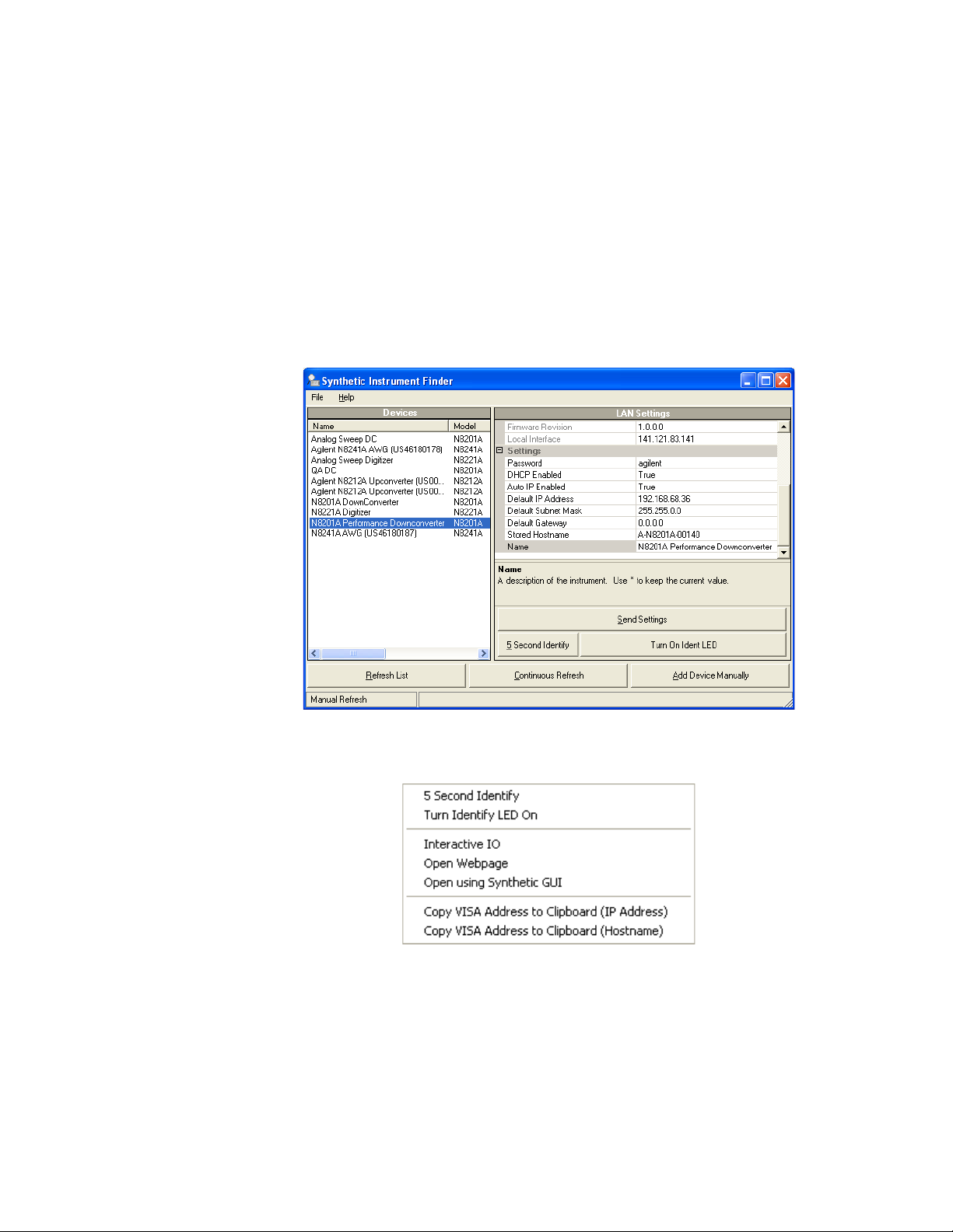
The Synthetic Instrument Finder window is divided into two main sections:
• right pane contains information specific to the instrument highlighted in the left pane.
• left pane contains a list of equipment available on your LAN for connection.
Right-Pane Functions
Send Settings Sends the current instrument settings to the N8201A performance
downconverter. Use this function if you modified the settings in Instrument Finder.
5 Second Identify Flashes the LAN LED for five seconds.
Turn On Ident LED When On, the LAN LED continuously flashes on and off. Once the
Turn On Ident LED button is pressed, the button name changes to Turn Off Ident LED.
Refresh List Updates the device’s list.
Continuous Refresh Updates the device’s list every one minute.
Add Device Manually Allows you to add a device for connection. Use this feature
only if your instrument does not appear in the Devices list.
a Click Add Device Manually. The Devices area will display a new listing titled
“Unknown”.
b In the Manual settings area, enter in the MAC address, serial number, and model
number of the device.
c In the LAN settings area, enter in the information for the new device. (Make sure
that you scroll down the list to get to the editable settings area.)
d Click Send Settings to enter this information in the Devices area.
e Double-click the new listing to open the webpage, or right-click and select Open
using Synthetic GUI to use the virtual interface.
52 Agilent N8201A Performance Downconverter Synthetic Instrument Module, 3 Hz to 26.5 GHz
Page 57

Hardware Setup and Configuration 2
Left-Pane Functions
In the left pane, right-click on the N8201A performance downconverter and the
following menu should appear.
Interactive IO Opens the Agilent Interactive IO application which allows SCPI
commands to be sent to the instrument. (The Interactive IO option is only available if the
Agilent Connection Expert has been installed on the PC.)
Agilent N8201A Performance Downconverter Synthetic Instrument Module, 3 Hz to 26.5 GHz 53
Page 58

2 Hardware Setup and Configuration
Open Webpage Opens the Web page associated with the currently selected instrument.
From this Web page, settings for the instrument can be viewed and modified.
Tip: There are two other ways to access the device’s Web page:
• By double-clicking on the Device listing in the Synthetic Instrument Finder.
• By typing in the device’s hostname or IP address in your Internet browser.
Open using Synthetic GUI Opens the Synthetic Instrument GUI.
Copy VISA Address to Clipboard (IP Address) Copies the VISA IP address to the
clipboard for use in other applications.
Copy VISA Address to Clipboard (Hostname) Copies the VISA hostname to the
clipboard for use in other applications. It is recommended that you use this address on
networks with DHCP and DNS network capability.
54 Agilent N8201A Performance Downconverter Synthetic Instrument Module, 3 Hz to 26.5 GHz
Page 59

How to Reset the LAN Configuration
NOTE
Recessed
LAN RST
Button
On the instrument front panel, near the power switch, is a recessed button labeled
“RESET”. This button enables you to place the LAN configuration of the instrument
into a known state.
When this button is pressed (a straightened paper clip will do the job) the following
settings are made and the system reboots.
• Subnet Mask is set to 255.255.0.0
• DHCP is set to on
• Auto IP is set to on
• If DHCP and Auto IP are set to off, the IP address will be set to 192.168.EE.FF,
where EE and FF are the last two parts of the MAC address (AA.BB.CC.DD.EE.FF).
This is designed to prevent multiple instruments from using the same default IP
address (refer to the instrument label).
If you had manually configured LAN settings before, you may have to reconfigure your
instrument to reset DHCP and Auto IP to OFF. Refer to “How to Set a Static IP Address" on
page 56.
Hardware Setup and Configuration 2
• The instrument hostname is set to A-N82XXA-NNNNN, where N82XXA is the
instrument model number (such as N8201A) and NNNNN represents the last five
digits of the instrument serial number.
If the instrument is in an environment with a DHCP server, it is assigned an IP address
through DHCP. The IP address can be found by using the instrument hostname as the
URL in a web browser.
Without DHCP, the instrument will use Auto IP and acquire a 169.254.X.X address. If
no DHCP is present, but the instrument is set to use DHCP (the default), the instrument
will wait two minutes for its DHCP request to time out. In this case, there is a time delay
of approximately three minutes between when the instrument is powered on and when it
is usable.
Agilent N8201A Performance Downconverter Synthetic Instrument Module, 3 Hz to 26.5 GHz 55
Page 60

2 Hardware Setup and Configuration
NOTE
How to Set a Static IP Address
The DHCP server automates the process of setting up the IP addresses on your network
by default. When the N8201A performance downconverter is turned on, it searches for a
DHCP server on the network and selects a “dynamic IP address”. Each time the
N8201A performance downconverter is rebooted, the N8201A performance
downconverter may get a different IP address. To set the N8201A performance
downconverter to a static IP address, rather than allowing the DHCP server to select an
auto IP address:
1 Assign a N8201A performance downconverter instrument IP address that will work with
your computer.
F
For a company wide network, your system administrator will have to assign an IP address
that is compatible with your PC. If you have a private LAN network or a direct connection
from your PC to the instrument, you can assign the IP address. Refer to “Step 1. Unpack the
N8201A Performance Downconverter" on page 28.
2 Connect the N8201A performance downconverter in one of the following two
configurations:
• Connect a LAN cable from the LAN connector on your PC to an empty connector on
your internal local area network or LAN hub. Connect a LAN cable from the LAN
connector on the rear panel of the N8201A performance downconverter to an empty
connector on your internal local area network or LAN hub.
Figure 1 Connecting the PC LAN cable to a company/private LAN to the instrument LAN
• Connect a cross-over cable from the LAN connector on your PC to the LAN
connector on the rear panel of the N8201A performance downconverter.
56 Agilent N8201A Performance Downconverter Synthetic Instrument Module, 3 Hz to 26.5 GHz
Page 61

Hardware Setup and Configuration 2
Figure 2 Connecting the PC LAN cable to the instrument LAN (cross-over cable)
3 Turn on power to the PC.
4 Turn on power to the N8201A performance downconverter and wait until the LAN LED
turns solid green; this takes about 60 seconds.
5 From the Windows Desktop,
click Start > All Programs > Agilent SI Tools > Synthetic Instrument Finder.
The following Synthetic Instrument Finder dialog box should appear.
6 Select the N8201A performance downconverter listed in the Agilent Synthetic
Instrument Finder dialog box to access the N8201A performance downconverter Web
page.
Agilent N8201A Performance Downconverter Synthetic Instrument Module, 3 Hz to 26.5 GHz 57
Page 62

2 Hardware Setup and Configuration
7
Click View & Modify LAN Config in the left-pane of the Web page. The following dialog
box should appear.
8 Click Modify Configuration to access the Password dialog.
9 Click Submit (accept the default password) and the following dialog box should appear.
The default password is set to “agilent”.
Tip: You can change the password from the View & Modify LAN Connections. (Scroll
down the Parameter column until you locate the Change Password parameter.)
58 Agilent N8201A Performance Downconverter Synthetic Instrument Module, 3 Hz to 26.5 GHz
Page 63

Hardware Setup and Configuration 2
NOTE
10
Change the DHCP and Auto IP radio-buttons to Off. Change the IP address, Subnet
Mask, and Default Gateway values to meet your network requirements.
11 Click Save to save the new settings. Parameters marked with an asterisk (*) also require
that you click "Renew LAN settings" before changes take effect.
For the new settings to become effective, you may first cycle the power of the instrument
and then cycle the power of the PC.
Agilent N8201A Performance Downconverter Synthetic Instrument Module, 3 Hz to 26.5 GHz 59
Page 64

2 Hardware Setup and Configuration
How to Troubleshoot Connectivity Problems on the Network
The Synthetic Instrument Finder program is used to find instruments on a network when
the N8201A performance downconverter is connected through a router or cross-over
cable. There are three possible configurations:
• connecting the PC through a company wide site LAN connection to the
N8201A performance downconverter
• connecting the PC to the same private LAN network as the instrument
• connecting the PC directly to the instrument using a cross-over cable - this would
typically be used for troubleshooting and is not normally used to control an
instrument directly
The N8201A performance downconverter is shipped with a default IP address. This
default IP address is 192.168.EE.FF, where EE and FF are the last two parts of the
Media Access Control (MAC) address (AA.BB.CC.DD.EE.FF).
How to Determine a PCs Configuration Settings
From a DOS Window
1 From the Windows Desktop, click Start > Run.
2 At the Open: prompt, type CMD and press Enter to open a DOS window.
3 At the command prompt, type ipconfig/all to display the PCs network connection
details.
Or,
From the PCs Control Panel
1 From the Windows Desktop, click Start > Settings > Control Panel > Network and
Internet Connections.
2 From the Network and Internet Connections window, double-click the Local Area
Connection.
3 In the Local Area Connection Status dialog, click the Support tab and click Details to
display the PCs Network Connection Details.
The Network Connection Details include:
• Physical Address
• DHCP status, enabled or disabled (displayed when using the DOS window ipconfig
command only)
• Auto configuration enabled or disabled (displayed when using the DOS window
ipconfig command only)
• IP Address
• Subnet Mask
60 Agilent N8201A Performance Downconverter Synthetic Instrument Module, 3 Hz to 26.5 GHz
Page 65

• Default Gateway
• DHCP Server Address
• Lease Obtained
• Lease Expired
• Primary WINS Servers
• Secondary WINS Servers
Hardware Setup and Configuration 2
Agilent N8201A Performance Downconverter Synthetic Instrument Module, 3 Hz to 26.5 GHz 61
Page 66

2 Hardware Setup and Configuration
If the Instrument was Unable to Join the LAN
or
If the LAN LED is Red
Symptom
Possible Causes Possible Solutions
The instrument is not connected to a LAN. If connecting the instrument to a switch or hub, verify
that the instrument is connected with a standard LAN
cable.
An incorrect LAN cable is being used.
• If connecting the instrument directly to a PC, verify
that the instrument is connected with a cross-over
cable.
• If connecting the instrument to a switch or hub,
verify that the instrument is connected with a
standard LAN cable.
The device’s LAN port is not active. Connect the instrument to a known working LAN
port.
The device is configured to use DHCP, but no DHCP
server is available.
• Disable DHCP. Refer to “How to Set a Static IP
Address" on page 56.
• Connect the device to a LAN that uses a DHCP
server.
The instrument is configured to use a duplicate static
IP address.
• Make sure that no other device is using the same
IP address as your instrument.
• Configure your instrument to use a different IP
address. Refer to “How to Set a Static IP
Address" on page 56.
62 Agilent N8201A Performance Downconverter Synthetic Instrument Module, 3 Hz to 26.5 GHz
Page 67

Hardware Setup and Configuration 2
If the Instrument’s IP Address or Hostname Cannot be Found with Ping
Possible Causes Possible Solutions
The instrument was unable to join the LAN. See “If the Instrument was Unable to Join the
LAN" on page 62.
The instrument’s LAN settings are incorrect. Verify that the instrument’s settings are appropriate
for your LAN.
A firewall is preventing communication between your
PC and your instrument.
The instrument is using Auto-IP (That is, the
instrument assigned itself a 169.254.x.x IP address)
and your PC is not using Auto IP (That is, PC does not
have a 169.254.x.x IP address.)
Make sure that your firewall settings allow
communication between your PC and other devices.
• Disable Auto-IP on the instrument.
• Configure your PC to use Auto-IP.
If the Instrument is Not Found by the Synthetic Instrument Finder
Possible Causes Possible Solutions
The instrument was unable to join the LAN. See “If the Instrument was Unable to Join the
LAN" on page 62.
The instrument and PC are on different
switches/hubs and different subnets.
• Put the instrument on the same switch or hub as
your PC.
• If the instrument is using DHCP, make sure that the
instrument and the PC are put on the same subnet.
• If the instrument is using a static IP address, make
sure that the instrument IP address and subnet
mask put the instrument on the same subnet as
your PC.
If the Instrument’s Hostname and PC Cannot Communicate
Possible Causes Possible Solutions
No DNS server is available. Communicate with the instrument using the
instrument’s IP address.
The DNS server has not been updated. Wait several minutes.
The PC cannot communicate with the device over
LAN.
Agilent N8201A Performance Downconverter Synthetic Instrument Module, 3 Hz to 26.5 GHz 63
See “If the Instrument’s IP Address or Hostname
Cannot be Found with Ping" on page 63.
Page 68

2 Hardware Setup and Configuration
If the Instrument Web Page is Not Visible
Possible Causes Possible Solutions
• The instrument has not yet joined the LAN.
See “If the LAN LED is Red" on page 62.
• The instrument is unable to join the LAN.
Your PC cannot communicate with the device over
your LAN.
You are attempting to use the device’s hostname and
the hostname is not working.
Your browser is configured to use a proxy, and the
proxy does not allow communication with
instruments on the LAN.
See “If the Instrument was Unable to Join the
LAN" on page 62.
See “If the Instrument’s Hostname and PC Cannot
Communicate" on page 63.
Disable or reconfigure the proxy settings. Open
Internet Explorer and select Tools > Internet Options
> Connections > LAN Settings…
If the Software Driver Will Not Open the Connection
Possible Causes Possible Solutions
Your PC cannot communicate with the device over
your LAN.
Someone else is currently connected to the
instrument.
See “If the Instrument’s IP Address or Hostname
Cannot be Found with Ping" on page 63.
Make sure that no one else is connected to the
instrument.
64 Agilent N8201A Performance Downconverter Synthetic Instrument Module, 3 Hz to 26.5 GHz
Page 69

User’s Guide
3
Using the
Agilent
“Starting the Agilent Synthetic Instrument GUI" on page 67
“Features of the Agilent Synthetic Instrument GUI" on page 69
“Settings on the Agilent Synthetic Instrument GUI" on page 74
Synthetic Instrument GUI
Agilent Technologies
65
Page 70

3 Using the Agilent Synthetic Instrument GUI
NOTE
Although only one interface can be used at any given time, the N8201A performance
downconverter can be controlled with any of the following:
• Agilent N8201A Option H02 Spectrum Analyzer GUI
• SA Remote Web Server
• Agilent Synthetic Instrument GUI
Which interface should be used:
• If Option H02 is not installed, the N8201A performance downconverter can be manually
controlled using the Agilent Synthetic Instrument GUI; without Option H02, the
N8201A performance downconverter cannot be controlled with SCPI commands.
• If Option H02 is installed, you can use either the Agilent N8201A Option H02 Spectrum
Analyzer GUI, the SA Remote Web Server, or the Agilent Synthetic Instrument GUI.
(For information on using these different interfaces, refer to “(Optional) Step 4. Connect
to the Agilent N8201A Option H02 Spectrum Analyzer GUI" on page 34, “(Optional) Step
5. Connect to an SA Remote Web Server" on page 36, or “Starting the Agilent Synthetic
Instrument GUI" on page 67.)
To verify that Option H02 is installed:
1 Start the Synthetic Instrument Finder (from the Windows Desktop,
click Start > All Programs > Agilent SI Tools > Synthetic Instrument Finder).
2 Select an instrument, from the left-hand pane of the Synthetic Instrument Finder, and
right-click on the instrument with the mouse.
3 Select Interactive IO.
4 Ty p e *OPT? at the Command prompt and click Send & Read.
5 Read the response in the Instrument Session History box; the required option should be
listed as H02.
66 Agilent N8201A Performance Downconverter Synthetic Instrument Module, 3 Hz to 26.5 GHz
Page 71

Starting the Agilent Synthetic Instrument GUI
This section describes how to access and use the Agilent Synthetic Instrument GUI.
1 From the Windows Desktop,
click Start > All Programs > Agilent SI Tools > Agilent Synthetic Instrument GUI.
2 Click Connection Manager (lower-left corner)
on the Agilent Synthetic Instrument GUI dialog box.
Using the Agilent Synthetic Instrument GUI 3
3 Click Find Instruments (lower-left corner) on the Connect to Instrument dialog box.
Agilent N8201A Performance Downconverter Synthetic Instrument Module, 3 Hz to 26.5 GHz 67
Page 72

3 Using the Agilent Synthetic Instrument GUI
4
Select an N8201A performance downconverter and click Tes t (lower-left corner) on the
Connect to Instrument dialog box.
• If the bottom of the dialog box displays the message “Connection Succeeded“, the
instrument was found and communication has been established.
• If the bottom of the dialog box displays the message “N8201A is not supported”, the
instrument is not communicating. Refer to “Troubleshooting" on page 50.
5 Click Connect (lower-right corner) on the Connect to Instrument dialog box and the
following dialog box should appear.
If the Agilent Synthetic Instrument GUI appears, the N8201A performance downconverter
has successfully connected using a LAN connection!
Left Pane
The lower portion of the left pane displays the settings available for adjustment on the
N8201A performance downconverter. Click a function button to activate that function and
the related functions are displayed in the Properties area. For example, Center Frequency is
the active function and all settings associated with Center Frequency are available for
modification.
Right Pane
The upper portion of the right pane always displays the functions that are most commonly
used for a measurement. These functions are also accessible from the left pane. Changing
one of these parameters changes the setting in the left pane as well.
The lower portion of the right pane can have three tabs: Dynamic Help, Instrument
Information, and the Event Log. For more information on theses areas, refer to “Dynamic
Help" on page 72, “Instrument Information" on page 73, and “Event Log" on page 73.
68 Agilent N8201A Performance Downconverter Synthetic Instrument Module, 3 Hz to 26.5 GHz
Page 73

Using the Agilent Synthetic Instrument GUI 3
Features of the Agilent Synthetic Instrument GUI
File Menu
The File menu accesses options for instrument connection, save and recall settings, and
exiting the application. Theses tasks are also available by clicking the icons on the tool bar.
Figure 3 File sub menu
Connect
Accesses the Connect to Instrument dialog box which is used to connect to an instrument
on the LAN hub.
Figure 4 Connect to Instrument Window
Reconnect
Re-establishes the connection to the instrument if the instrument has been disconnected.
Agilent N8201A Performance Downconverter Synthetic Instrument Module, 3 Hz to 26.5 GHz 69
Page 74

3 Using the Agilent Synthetic Instrument GUI
Disconnect
Terminates the connection to the active instrument that is using the
Synthetic Instrument GUI.
Load Settings
Accesses the Load Instrument Properties dialog box where you can recall user-definable
instrument settings.
Save Settings
Accesses the Save Instrument Properties dialog box where you can save instrument
settings for use at a later time.
Exit
Closes the Agilent Synthetic Instrument GUI application.
Help
The Help menu displays the current versions of the GUI and drivers.
Figure 5 Help About Synthetic GUI
70 Agilent N8201A Performance Downconverter Synthetic Instrument Module, 3 Hz to 26.5 GHz
Page 75

Left Pane
Using the Agilent Synthetic Instrument GUI 3
Start Page
The Start Page lists the instruments previously connected to the Agilent Synthetic
Instrument GUI.
Error Log
Displays a history of all instrument and GUI related errors and messages.
Figure 6 Error Log
Connection Manager Accesses the Connect to Instrument dialog box.
Table 1 Controls available from the Connect to Instrument Dialog Box
Saved Connections Accesses user defined connections.
Recent Connections Displays a list of instruments that have recently been controlled by the
Agilent Synthetic Instrument GUI.
Connection Expert Accesses Agilent Connections Expert.
Find Instruments Lists the instruments found in Instrument Finder.
Test Tests the connection between the PC and the highlighted instrument.
Agilent N8201A Performance Downconverter Synthetic Instrument Module, 3 Hz to 26.5 GHz 71
Page 76

3 Using the Agilent Synthetic Instrument GUI
Right Pane
The upper portion of the right pane always displays the functions that are most commonly
used for a measurement. These functions are also accessible from the left pane. Changing
one of these parameters changes the setting in the left pane as well.
The lower portion of the right pane can have the following tabs: Dynamic Help, Instrument
Information, and Event Log.
Dynamic Help
Provides information about the function currently selected in the left pane.
Figure 7 Dynamic Help
72 Agilent N8201A Performance Downconverter Synthetic Instrument Module, 3 Hz to 26.5 GHz
Page 77

Using the Agilent Synthetic Instrument GUI 3
Instrument Information
Provides information about your N8201A performance downconverter such as the serial
number, IP address, software revision used, and so on.
Figure 8 Instrument Information Page
Event Log
When enabled in the Events parameters area, displays the event log history.
Figure 9 Event Log History
Agilent N8201A Performance Downconverter Synthetic Instrument Module, 3 Hz to 26.5 GHz 73
Page 78

3 Using the Agilent Synthetic Instrument GUI
Settings on the Agilent Synthetic Instrument GUI
Frequency
Sets the center frequency or frequency offset of the N8201A performance downconverter.
Center Frequency
Sets the center frequency while the span remains constant. The frequency range of the
N8201A performance downconverter is 3 Hz to 26.5 GHz plus the frequency offset. If the
External Mixer Enabled equals External, the frequency range is 3 Hz to 335 GHz.
Frequency Offset
Enables you to input a frequency offset value to account for external frequency
conversions. This value is added to the display readout of the marker frequency, center
frequency, start frequency, stop frequency, and all other absolute frequency settings. Limits
are
−500 THz to 500 THz.
Frequency List
Sets up a list of frequencies for the instrument to step through. The list begins with Start
Frequency, and adds the Step Frequency until the Stop Frequency is reached. The next
trigger causes the list to be repeated.
Disabled Prevents a frequency step sequence from being initiated.
Start Sets the first frequency that will be swept on a list sweep.
Stop Sets the last frequency that will be swept before the list is repeated.
Step Sets the difference between successive swept frequencies.
Trigger Se t u p Sets up the trigger that will be used to step through the frequency list.
Trigger Source
Sets the source of triggers. When the specified trigger occurs, the instrument will move to
the next frequency in its frequency list. Possible values are:
EXT - TTLLX10LX11LX12LX13
LX14 LX15 LX16 LX17 LAN0
LAN1 LAN2 LAN3 LAN4 LAN5
LAN6 LAN7 ALARM0
74 Agilent N8201A Performance Downconverter Synthetic Instrument Module, 3 Hz to 26.5 GHz
Page 79

Using the Agilent Synthetic Instrument GUI 3
Trigger Source (set to ALARM0)
Table 2 Controls available when Trigger Source is set to ALARM0
Alarm Mode Defines the way that Alarm Time will be interpreted. In absolute mode,
the alarm will begin firing at the time of day specified in Absolute Alarm
Time. In relative mode, the alarm will begin firing at a time relative to
when the alarm is set up.
Relative Alarm Time Defines the number of seconds after pressing Execute Trigger that the
first alarm will occur.
Absolute Alarm Time Defines the time that the first alarm will occur.
Alarm Period Defines the time between successive alarms.
Alarm Repeat Defines the number of times the alarm will be repeated.
A value of 1 means that the alarm will occur once and will not be
repeated. A value of 2 means that the alarm will occur twice.
A value of 0 means that the alarm will be repeated until the alarm is
disabled.
Trigger Detection
Controls the trigger polarity. It is Positive to trigger on a rising edge and Negative to trigger
on a falling edge.
Execute Trigger
Sends the new trigger settings to the instrument
Agilent N8201A Performance Downconverter Synthetic Instrument Module, 3 Hz to 26.5 GHz 75
Page 80

3 Using the Agilent Synthetic Instrument GUI
Level
Sets the input attenuation. The input attenuation can be set from 0 to 70 dB in 2 dB
steps.The input impedance is set to 50 ohms. Input attenuation is used to minimize
compression caused by a signal level that is too high in amplitude.
Input RF
Accesses the functions to select the input signal source (choices are RF, 50 MHz Cal, or
External Mixer), enable a preamplifier, and to set the coupling to either AC or DC.
IF Output
Accesses the functions to set the IF Bandwidth and IF Frequency.
Table 3 Grouped Values
IF Output IF Bandwidth
IF Output 1 0 to 3 MHz 21.4 MHz 50 Ohm
IF Output 2 100 MHz 321.4 MHz 50 Ohm
IF Output 3 10 MHz 7.5 MHz 50 Ohm
Reference Oscillator
Allows you to use either the internal or an external reference oscillator for making
measurements.
Reference Output
Switches the 10 MHz out signal on the front panel of the N8201A performance
downconverter On and Off.
Reference Input Source
Specifies whether to use an External or Internal source for the reference oscillator. If set to
External, a value must be specified for External Frequency with limits from 1 MHz to
30 MHz.
Limits
IF Frequency
Limits
Input Impedance
Limits
76 Agilent N8201A Performance Downconverter Synthetic Instrument Module, 3 Hz to 26.5 GHz
Page 81

Preselector (Option 123)
Adjust
Allows you to manually adjust the preselector filter center frequency to optimize its
response on the signal of interest. When enabled, the center frequency must be set to
3.045 GHz or greater.
Limits are: –250 MHz to 250 MHz.
PreSelector Enabled
Enables or disables the preselector.
Enabled: Can be set if the Center Frequency is greater than 3.045000000 GHz.
Possible Values: Enabled, Disabled
Peak
Using the Agilent Synthetic Instrument GUI 3
Performs a peak search.
Enabled: Can run if Center Frequency is greater than 3.045000000 GHz.
Instrument Functions: A - L
External Mixer
Selects either the internal mixer or an external mm-wave mixer.
• When Internal mixing is selected, normal operation and all other external mixing
functions are unavailable.
• When External mixing is selected, you can analyze high frequency signals (that is,
higher than the spectrum analyzer’s maximum frequency) by using an appropriate
external mixer.
Band Selects a band, or sets the frequency band to be user defined.
User Defined values:
• K - 18 to 26.5 GHz
• A - 26.5 to 40 GHz
• Q - 33 to 50 GHz
• U - 40 to 60 GHz
• V - 50 to 75 GHz
• E - 60 to 90 GHz
• W - 75 to 110 GHz
• F - 90 to 140 GHz
• D - 110 to 170 GHz
Agilent N8201A Performance Downconverter Synthetic Instrument Module, 3 Hz to 26.5 GHz 77
Page 82

3 Using the Agilent Synthetic Instrument GUI
• G - 140 to 220 GHz
• Y - 170 to 260 GHz
• J - 220 to 325 GHz
Harmonic A user defined frequency band. Limits are −50 to −1 or 1 to 50.
Mixer Bias Turns on/off the mixer bias and adjusts an internal bias source for use with
external mixers. The bias signal is present on the center conductor of the IF INPUT
connector on the front panel.
Bias Level Sets the bias level. Limits are −10 mA to 10 mA.
Calibration
Accesses the Align system and immediately executes an alignment cycle of all the
subsystems (Align RF, Align IF, Align ADC, and Align Current Sys Gain). The instrument will
change any current system settings currently underway, perform the full alignment, and
then return to the current system settings that were in place before the calibration began.
A calibration nominally takes 35 seconds to perform.
The N8201A downconverter will meet its specifications when:
• It is stored a minimum of two hours within the operating temperature range and turned
on for at least 30 minutes followed by a calibration.
• When a calibration has been performed within the past 24 hours or when the
temperature changes 3 °C.
• The front panel 1
st
LO OUT connector is terminated with a 50 ohm load.
Events (Settling Events and Event Logging)
Settling Event
Allows you to define the parameters of the Settling Event. The Settling Event has a positive
edge when the frequency is set and a negative edge when the system is stabilized.
Settling Channel
Selects the channel to configure. Possible values are:
LXI0 LXI1 LXI2 LXI3
LXI4 LXI5 LXI6 LXI7
LAN0 LAN1 LAN2 LAN3
LAN4 LAN5 LAN6 LAN7
78 Agilent N8201A Performance Downconverter Synthetic Instrument Module, 3 Hz to 26.5 GHz
Page 83

Using the Agilent Synthetic Instrument GUI 3
NOTE
Settling Mode
Selects the operating mode for the Settling Channel: Disabled, Driven, or Wired OR.
Wired OR is only available for LXI channels.Use Wired OR if more than one instrument is
driving the LXI channel. When only one instrument is driving the LXI channel then use the
Driven mode.
Settling Destination Path
The target of the LAN event. The Settling Destination Path can be either an IP address, a
hostname, or 'All'. (The function is only visible if Settling Channel is a LAN channel and can
be set if the Settling mode is not Disabled.)
Settling Slope
Determines whether an event will occur on positive or negative edges. Possible values are:
Positive or Negative.
Settling mode must be enabled for Settling Slope to be set.
Execute Settling Event
Starts a settling event after all of the parameters are define.
Event Logging
When enabled, a history of all instrument errors and messages are displayed.
Enable Logging
Enables or disables event logging.
Event Log
Displays the event log in the right pane when the Event Log page is selected.
Clear Event Log
Clears the event log.
Disable All Events
Prevents any previously events from occurring.
Agilent N8201A Performance Downconverter Synthetic Instrument Module, 3 Hz to 26.5 GHz 79
Page 84

3 Using the Agilent Synthetic Instrument GUI
Preset
Sets the instrument to a known state and clears any current settings.
Refresh All Values
Re-reads the settings from the instrument.
80 Agilent N8201A Performance Downconverter Synthetic Instrument Module, 3 Hz to 26.5 GHz
Page 85

User’s Guide
CAUTION
4
Front and Rear Panel Features
“N8201A Performance Downconverter Front Panel Features" on page 82
“N8201A Performance Downconverter Rear Panel Features" on page 87
“Interconnect Cabling" on page 89
“Operational Considerations" on page 90
Electrostatic discharge (ESD) can damage the highly sensitive components in your
instrument. ESD damage is most likely to occur as the instrument is being installed
or when cables are connected and disconnected. Protect the circuits from ESD
damage by wearing a grounding strap that provides a high resistance path to
ground. Alternately, ground yourself to discharge any static charge built-up by
touching the outer shell of any grounded instrument chassis before touching the
port connectors.
Agilent Technologies
81
Page 86

4 Front and Rear Panel Features
Option V7L
Option 219
CAUTION
N8201A Performance Downconverter Front Panel Features
Figure 10 N8201A performance downconverter front panel features
RF INPUT
The input for an external 3 Hz to 26.5 GHz RF signal. If AC Coupled, the range is
20 MHz to 26.5 GHz.
The total power of all signals at the downconverter input must not exceed +30 dBm
(1 watt).
Power
The front panel power switch is a standby switch only; it is not a LINE switch (power
disconnecting device). When in Standby, the LED is amber, When ON the LED is green.
82 Agilent N8201A Performance Downconverter Synthetic Instrument Module, 3 Hz to 26.5 GHz
Page 87

Line Power LED
The power indicator has the following states:
State Power Status Illumination
OFF No power connected to rear panel None
Front and Rear Panel Features 4
LAN LED
Standby Standby power. This is not a LINE
switch or power disconnecting device.
ON Power is on Solid green
Solid amber
The green LED indicates when the downconverter standby switch is set to the on position.
The green LED is off when the switch is in the standby position.
The yellow LED indicates when the downconverter standby switch is set to the standby
position. The yellow LED is off when the switch is in the on position
The LAN LED indicator works in the following states:
State of the LAN LAN Status Illumination
ON Normal operation Solid green
ON Device identity. Blinking green
OFF LAN error fault:
Solid Red
• No valid or duplicate IP address
• Unable to obtain or renew previously
obtained DHCP lease.
• Disconnected LAN cable
OFF This is the state when:
None
• The system is initializing
or
• A LAN reset has be initialized
Agilent N8201A Performance Downconverter Synthetic Instrument Module, 3 Hz to 26.5 GHz 83
Page 88

4 Front and Rear Panel Features
NOTE
1588 LED
The IEEE 1588 LED clock status has the following states:
State of the Clock Clock Status Illumination
OFF Not synchronized None
ON Synchronized, clock is IEEE 1588 Slave Solid green
ON Synchronized, clock is IEEE 1588 Master Blinking green (once
every second)
ON Synchronized, clock is IEEE 1588 to
OFF IEEE 1588 is in a fault state Solid red
COHERENT CARRIERS
Do not remove the cables connecting the coherent carrier inputs and outputs. These cables
are connected at the factory and must remain so for proper instrument operation.
3-7 GHz 1st LO In Provides the 1st LO input signal (3 to 7 GHz) to the downconverters
internal LO distribution circuitry.
3-7 GHz 1st LO Out Provides the 1st LO output signal (3-7 GHz at +15 dBm max) as a
coherent carrier reference for phase locking two receivers.
3.6 GHz 2nd LO In Provides the 2st LO input signal (3.6 GHz) to the downconverters
internal LO distribution circuitry.
3.6 GHz 2nd LO Out Provides the 2nd LO output signal (3.6 GHz at +3 dBm) as a
coherent carrier reference for phase locking two receivers.
Grand Master
Blinking green (once
every two seconds
84 Agilent N8201A Performance Downconverter Synthetic Instrument Module, 3 Hz to 26.5 GHz
Page 89

EXT MIXER
1st LO Out The 1st LO output (3-7 GHz at +15 dBm max) allows connections for external
mixing. The 1st LO output routes the internal first LO signal to an external mixer, which uses
the higher harmonics to mix with the high frequency signals. The external mixer’s IF output
connects to the downconverter’s IF input port.
Pre-Sel Out The Preselected external mixer tune output offers tuning voltage for a
preselected mixer.
IF In (Option AYZ) The IF input (321.4 MHz Nominal at -20 dBm, +10 dBm max) allows
connections for external mixing. This port is only functional when Option AYZ is ordered.
IF OUTPUTS
321.4 MHz The 321.4 MHz IF output signal is present. Conversion gain is nominally +2 to
+4 dB (with 0 dB input attenuation). Conversion gain varies nominally ±3 dB as a function
of tune frequency. The conversion gain drops at higher frequencies.
Front and Rear Panel Features 4
21.4 MHz The 21.4 MHz IF output signal is present. Conversion gain is nominally
+10 dB (with 0 dB input attenuation). The conversion gain drops at higher frequencies.
7.5 MHz The 7.5 MHz IF output signal is present. The 7.5 MHz output signal is at
nominally at +13 dBm.
TRIGGERS
These SMB trigger input and output connectors are used to control the waveforms and
create event-based signal simulation. These connectors support LVTTL logic levels.
In allows external triggering of measurements.
Out used to synchronize other test equipment with the downconverter.
REFERENCES
1 - 30 MHz In Selects an external reference to phase lock all oscillators in the
instrument. You can select any external reference frequency between 1 and 30 MHz.
10 MHz Out A switched output of the analyzer’s internal 10 MHz reference signal locks
other test equipment to the same frequency reference used by the downconverter. The
10 MHz out signal is at +5 dB.
Agilent N8201A Performance Downconverter Synthetic Instrument Module, 3 Hz to 26.5 GHz 85
Page 90

4 Front and Rear Panel Features
IF LOG VIDEO (Option V7L)
321.4 MHz In
Connector SMB male
Impedance of 50 ohm (nominal)
Video Out
Connector SMB male
Impedance of 50 ohm (nominal)
Maximum input power +10 dBm
NOISE SOURCE +28 V (PULSED) (Option 219)
VGA OUT
Connector BNC female
Output voltage On 28.0 +/- 0.1 V (60 mA maximum)
Off < 1 V
Connector VGA compatible, 15-pin mini D-SUB
Format VGA (31.5 kHz horizontal, 60 Hz vertical sync rates, non-interlaced) Analog RGB
Resolution 640 x 480
86 Agilent N8201A Performance Downconverter Synthetic Instrument Module, 3 Hz to 26.5 GHz
Page 91

Front and Rear Panel Features 4
N8201A Performance Downconverter Rear Panel Features
Figure 11 N8201A performance downconverter rear panel features
AC Power Receptacle
The AC voltage is connected here. The power cord receptacle accepts a
three-pronged power cable that is shipped with the N8201A performance
downconverter. The voltage range is 100/120/220/240 volts with a frequency range of
50 to 60 Hz and is automatically selected by the power supply.
LAN
This LAN interface allows ethernet local area network communication through a 100BaseT
LAN cable.
Agilent N8201A Performance Downconverter Synthetic Instrument Module, 3 Hz to 26.5 GHz 87
Page 92

4 Front and Rear Panel Features
NOTE
Trigger Bus Terminators
Trigg er
Bus
Trigg er
Bus
Trigg er
Bus
Trigg er
Bus
Trigg er
Bus
Star Hub
Trigge r
Bus
Trigge r
Bus
Trigger
Bus
Trigger
Bus
Trigge r
Bus
Trigger Bus Terminators
LXI Trigger Bus
The LXI (LAN eXtensions for Instrumentation) Trigger Bus is a hardware bus providing eight
trigger channels using M-LVDS (low-voltage differential signaling). Cables connect various
instruments together in a daisy chain or star configuration. Any instrument in a cluster can
send or receive triggers on any of the channels.
For more information about the LXI Trigger Bus and LAN triggering, refer to the following
“LXI Consortium” white papers on your “Agilent N8201A Performance Downconverter
Documentation CD”:
•
White_Paper_1_The_Appliaction_of_IEEE_1588_to_Test_and_Measurement_System
• White_Paper_2_LXI_Triggering
• White_Paper_3_Wired_Trigger_Bus_Physical_Aspects
Star Daisy-chain
USB
This is not a functional connector.
DB-9 (TEST)
This connector is for factory testing only.
88 Agilent N8201A Performance Downconverter Synthetic Instrument Module, 3 Hz to 26.5 GHz
Page 93

Interconnect Cabling
1-30MHz In
10M Hz Out
300 M Hz
12
3
21.4MHz 7.5M Hz
Pre-S el O u t IF In
REFERENCES
In Out
TRIGGERS
IF OU T PU T S
3.6 G Hz
2nd LO Out
3-7GHz
1st LO Out
3.6 G Hz
2nd LO In
3-7GHz
1st LO In
COHERENT CARRIERS
1st
LO Out
EXT
MIXER
EXT MIXER
RF INPUT 50
0VDC
30 dB m Ma x
Power
N8201A
Performance Dow nconverter
3H z - 26. 5 GH z
IN OU T IN OU T
IN OU T
IF IN PUT
30 M Hz EX T C L O C K10 M Hz RE F
TRIGGER
RESET
STATUSLAN ERR
N8221A
30 M S/ s IF Digitiz er
Front and Rear Panel Features 4
Figure 12 Interconnect cabling for the N8221A IF digitizer/N8201A performance downconverter
Agilent N8201A Performance Downconverter Synthetic Instrument Module, 3 Hz to 26.5 GHz 89
Page 94

4 Front and Rear Panel Features
Operational Considerations
This section includes instructions for configuring a LAN interface to the
Agilent Technologies N8221A IF digitizer and the N8201A performance downconverter. The
instructions assume that the computer being used has a LAN card installed and is
configured for TCP/IP protocol.
Agilent 89601A Vector Signal Analysis Software
The Agilent Technologies 89601A vector signal analysis (VSA) software is the virtual
instrument interface for the N8221A IF digitizer/N8201A performance downconverter and
offers a wide range of troubleshooting tools for analyzing signals.
Configuring the Local Area Network (LAN) Interface
You must ensure that the IP addresses for your computer and
N8221A IF digitizer/N8201A performance downconverter are compatible, then configure
the LAN interface. The IP address consists of four groups of numbers separated by periods
(for example 169.254.xxx.xxx).
90 Agilent N8201A Performance Downconverter Synthetic Instrument Module, 3 Hz to 26.5 GHz
Page 95

User’s Guide
5
Preventive Maintenance
“Using, Inspecting, and Cleaning RF Connectors" on page 92”
“General Procedures and Techniques" on page 95
“Instrument Removal" on page 98”
“Instrument Installation" on page 100
This chapter provides preventative maintenance information, which should be reviewed
prior to working with the Agilent system. This information applies to all Agilent-supplied
instruments in the system and the system as a whole.
Agilent Technologies
91
Page 96

5 Preventive Maintenance
CAUTION
Using, Inspecting, and Cleaning RF Connectors
Taking proper care of cables and connectors will protect your system’s ability to make
accurate measurements. One of the main sources of measurement inaccuracy can be
caused by improperly made connections or by dirty or damaged connectors.
The condition of system connectors affects measurement accuracy and repeatability. Worn,
out-of-tolerance, or dirty connectors degrade these measurement performance
characteristics.
Repeatability
If you make two identical measurements with your system, the differences should be so
small that they will not affect the value of the measurement. Repeatability (the amount of
similarity from one measurement to another of the same type) can be affected by:
• Dirty or damaged connectors
• Connections that have been made without using proper torque techniques (this applies
primarily when connectors in the system have been disconnected, then reconnected).
Static-Sensitive Devices
This system contains instruments and devices that are static-sensitive. Always take
proper electrostatic precautions before touching the center conductor of any
connector, or the center conductor of any cable that is connected to any system
instrument. Handle instruments and devices only when wearing a grounded wrist or
foot strap. When handling devices on a work bench, make sure you are working on
an anti-static worksurface.
RF Cable and Connector Care
Connectors are the most critical link in a precision measurement system. These devices are
manufactured to extremely precise tolerances and must be used and maintained with care
to protect the measurement accuracy and repeatability of your system.
To extend the life of your cables or connectors:
• Avoid repeated bending of cables—a single sharp bend can ruin a cable instantly.
• Avoid repeated connection and disconnection of cable connectors.
• Inspect the connectors before connection; look for dirt, nicks, and other signs of damage
or wear. A bad connector can ruin the good connector instantly.
• Clean dirty connectors. Dirt and foreign matter can cause poor electrical connections
and may damage the connector.
• Minimize the number of times you bend cables.
• Never bend a cable at a sharp angle.
92 Agilent N8201A Performance Downconverter Synthetic Instrument Module, 3 Hz to 26.5 GHz
Page 97

• Do not bend cables near the connectors.
• If any of the cables will be flexed repeatedly, buy a back-up cable. This will allow
immediate replacement and will minimize system down time.
Before connecting the cables to any device:
• Check all connectors for wear or dirt.
• When making the connection, torque the connector to the proper value.
Proper Connector Torque
• Provides more accurate measurements
• Keeps moisture out of the connectors
• Eliminates radio frequency interference (RFI) from affecting your measurements
The torque required depends on the type of connector. Refer to Table 4 .
Never exceed the recommended torque when attaching cables.
Preventive Maintenance 5
Table 4 Proper Connector Torque
Connector Torque cm-kg Torque N-cm Torque in-lbs Wrench P/N
Type-N 52 508 45 hand tighten
3.5 mm 9.2 90 8 8720-1765
SMA 5.7 56 5 8710-1582
Connector Wear and Damage
Look for metal particles from the connector threads and other signs of wear (such as
discoloration or roughness). Visible wear can affect measurement accuracy and
repeatability. Discard or repair any device with a damaged connector. A bad connector can
ruin a good connector on the first mating. A magnifying glass or jeweler’s loupe is useful
during inspection.
SMA Connector Precautions
Use caution when mating SMA connectors to any precision 3.5 mm RF connector. SMA
connectors are not precision devices and are often out of mechanical tolerances, even
when new. An out-of-tolerance SMA connector can ruin a 3.5 mm connector on the first
mating. If in doubt, gauge the SMA connector before connecting it. The SMA center
conductor must never extend beyond the mating plane.
Agilent N8201A Performance Downconverter Synthetic Instrument Module, 3 Hz to 26.5 GHz 93
Page 98

5 Preventive Maintenance
WARNING
CAUTION
WARNING
WARNING
Cleaning Procedure
To prevent electrical shock, disconnect the module from mains before cleaning.
Use a dry cloth or one slightly dampened with water to clean the external case
parts. Do not attempt to clean internally.
1 Blow particulate matter from connectors using an environmentally-safe aerosol such as
Aero-Duster. (This product is recommended by the United States Environmental
Protection Agency and contains tetrafluoroethane. You can order this aerosol from
Agilent (see Tab l e 5).)
2 Use alcohol and a lint-free cloth to wipe connector surfaces. Wet a small swab with a
small quantity of alcohol and clean the connector with the swab.
3 Allow the alcohol to evaporate off of the connector before making connections.
Do not allow excessive alcohol to run into the connector. Excessive alcohol entering
the connector collects in pockets in the connector’s internal parts. The liquid will
cause random changes in the connector’s electrical performance. If excessive
alcohol gets into a connector, lay it aside to allow the alcohol to evaporate. This may
take up to three days. If you attach that connector to another device it can take
much longer for trapped alcohol to evaporate.
Table 5 Cleaning Supplies Available from Agilent
Product Part Number
Aero-Duster 8500-6460
Isopropyl alcohol 8500-5344
Lint-Free cloths 9310-0039
Small polyurethane swabs 9301-1243
Cleaning connectors with alcohol should only be performed with the
instruments’ mains power cord disconnected, in a well ventilated area.
Connector cleaning should be accomplished with the minimum amount of
alcohol. Prior to connector reuse, be sure that all alcohol used has dried, and that
the area is free of fumes.
If flammable cleaning materials are used, the material should not be stored, or
left open in the area of the equipment. Adequate ventilation should be assured to
prevent the combustion of fumes, or vapors.
94 Agilent N8201A Performance Downconverter Synthetic Instrument Module, 3 Hz to 26.5 GHz
Page 99

General Procedures and Techniques
GPIB Type Connector
This section introduces you to the various cable and connector types used in the system.
Read this section before attempting to remove or install an instrument! Each connector
type may have unique considerations.
Always use care when working with system cables and instruments.
Preventive Maintenance 5
Figure 13 GPIB, 3.5 mm, Type-N, power sensor, and BNC connectors
Agilent N8201A Performance Downconverter Synthetic Instrument Module, 3 Hz to 26.5 GHz 95
Page 100

5 Preventive Maintenance
Connector Removal
GPIB connectors
These are removed by two captured screws, one on each end of the connector; these
usually can be turned by hand. Use a flathead screwdriver if necessary.
GPIB connectors often are stacked two or three deep. When you are removing multiple
GPIB connectors, disconnect each connector one at a time. It is a good practice to connect
them back together even if you have not yet replaced the instrument; this avoids confusion,
especially if more than one instrument has been removed.
When putting GPIB connectors back on, you must again detach them from one another and
put them on one at a time.
Precision 3.5 mm connectors
These are precision connectors. Always use care when connecting or disconnecting this
type of connector. When reconnecting, make sure you align the male connector properly.
Carefully join the connectors, being careful not to cross-thread them.
Loosen precision 3.5 mm connectors on flexible cables by turning the connector nut
counter-clockwise with a 5/16 inch wrench. Always reconnect using an 8 inch-lb torque
wrench (Agilent part number 8720-1765). Semirigid cables are metal tubes, custom-formed
for this system from semirigid coax cable stock.
3.5 mm connectors with a gold hex nut
The semirigid cables that go to the RF outputs of some devices have a gold connector nut.
These do not turn. Instead, the RF connector on the instrument has a cylindrical connector
body that turns. To disconnect this type of connector, turn the connector body on the
instrument clockwise. This action pushes the cable’s connector out of the instrument
connector.
To reconnect, align the cable with the connector on the instrument. Turn the connector
body counterclockwise. You may have to move the cable slightly until alignment is correct
for the connectors to mate. When the two connectors are properly aligned, turning the
instrument’s connector body will pull in the semirigid cable’s connector. Tighten firmly by
hand.
3.5 mm connectors with a silver hex nut
All other semirigid cable connectors use a silver-colored nut that can be turned. To remove
this type of connector, turn the silver nut counter-clockwise with a 5/16 inch wrench.
When reconnecting this type of cable:
• Carefully insert the male connector center pin into the female connector. (Make sure the
cable is aligned with the instrument connector properly before joining them.)
96 Agilent N8201A Performance Downconverter Synthetic Instrument Module, 3 Hz to 26.5 GHz
 Loading...