

Page 1

Agilent
3.125 Gb/s Serial BERT
N5980A
User Guide
Page 2

Notices
© Agilent Technologies, Inc. 2006
No part of this manual may be reproduced in
any form or by any means (including electronic
storage and retrieval or translation into a
foreign language) without prior agreement and
written consent from Agilent Technologies,
Inc. as governed by United States and
international copyright laws.
Manual Part Number
N5980-91010
Edition
Revision 1.0 May 2006
Printed in Germany
Agilent Technologies, Deutschland GmbH
Herrenberger Str. 130
71034 Böblingen, Germany
For Assistance and Support
http://www.agilent.com/find/assist
For Product Updates
http://www.agilent.com/find/manufa
cturing_BERT
Warranty
The material contained in this document is
provided “as is,” and is subject to being
changed, without notice, in future editions.
Further, to the maximum extent permitted by
applicable law, Agilent disclaims all
warranties, either express or implied, with
regard to this manual and any information
contained herein, including but not limited to
the implied warranties of merchantability and
fitness for a particular purpose. Agilent shall
not be liable for errors or for incidental or
consequential damages in connection with
the furnishing, use, or performance of this
document or of any information contained
herein. Should Agilent and the user have a
separate written agreement with warranty
terms covering the material in this document
that conflict with these terms, the warranty
terms in the separate agreement shall
control.
Technology Licenses
The hardware and/or software described in
this document are furnished under a license
and may be used or copied only in accordance
with the terms of such license.
Restricted Rights Legend
If software is for use in the performance of a
U.S. Government prime contract or
subcontract, Software is delivered and licensed
as “Commercial computer software” as
defined in DFAR 252.227-7014 (June 1995), or
as a “commercial item” as defined in FAR
2.101(a) or as “Restricted computer software”
as defined in FAR 52.227-19 (June 1987) or any
equivalent agency regulation or contract
clause. Use, duplication or disclosure of
Software is subject to Agilent Technologies’
standard commercial license terms, and nonDOD Departments and Agencies of the U.S.
Government will receive no greater than
Limited Rights as defined in FAR 52.22719(c)(1-2) (June 1987). U.S. Government users
will receive no greater than Limited Rights as
defined in FAR 52.227-14 (June 1987) or DFAR
252.227-7015 (b)(2) (November 1995), as
applicable in any technical data.
Safety Notices
CAUTION
A CAUTION notice denotes a hazard.
It calls attention to an operating
procedure, practice, or the like that, if
not correctly performed or adhered to,
could result in damage to the product
or loss of important data. Do not
proceed beyond a CAUTION notice
until the indicated conditions are fully
understood and met.
WARNING
A WARNING notice denotes a
hazard. It calls attention to an
operating procedure, practice, or the
like that, if not correctly performed
or adhered to, could result in
personal injury or death. Do not
proceed beyond a WARNING notice
until the indicated conditions are
fully understood and met.
2 N5980A User Guide
Page 3

Safety Summary
General Safety Precautions
The following general safety
precautions must be observed during
all phases of operation of this
instrument. Failure to comply with
these precautions or with specific
warnings elsewhere in this manual
violates safety standards of design,
manufacture, and inte nded use of the
instrument.
Agilent Technologies Inc. assumes
no liability for the customer's failure
to comply with these requirements.
Before operation, review the
instrument and manual for safety
markings and instructions. You must
follow these to ensure safe operation
and to maintain the instrument in
safe condition.
General
This product is a Safety Class 1
instrument (provided with a
protective earth terminal). The
protective features of this product
may be impaired if it is used in a
manner not specified in the
operation instructions.
All Light Emitting Diodes (LEDs)
used in this product are Class 1
LEDs as per IEC 60825-1.
Environment Conditions
This instrument is intended for
indoor use in an installation category
II, pollution degree 2 environment. It
is designed to operate at a maximum
relative humidity of 95% and at
altitudes of up to 2000 meters.
Refer to the specifications tables for
the ac mains voltage requirements
and ambient operating temperature
range.
Before Applying Power
Verify that all safety precautions are
taken. The power cable inlet of the
instrument serves as a device to
disconnect from the mains in case of
hazard. The instrument must be
positioned so that the operator can
easily access the power cable inlet.
When the instrument is rack
mounted the rack must be provided
with an easily accessible mains
switch.
Ground the Instrument
To minimize shock hazard, the
instrument chassis and cover must
be connected to an electrical
protective earth ground. The
instrument must be connected to the
ac power mains through a grounded
power cable, with the ground wire
firmly connected to an electrical
ground (safety ground) at the power
outlet. Any interruption of the
protective (grounding) conductor or
disconnection of the protective earth
terminal will cause a potential shock
hazard that could result in personal
injury.
Do Not Operate in an Explosive
Atmosphere
Do not operate the instrument in the
presence of flammable gases or
fumes.
Do Not Remove the Instrument
Cover
Operating personnel must not
remove instrument covers.
Component replacement and internal
adjustments must be made only by
qualified personnel.
Instruments that appear damaged or
defective should be made
inoperative and secured against
unintended operation until they can
be repaired by qualified service
personnel.
Page 4
Safety Symbols on
Instruments
Indicates warning or caution. If
you see this symbol on a product,
you must refer to the manuals for
specific Warning or Caution
information to avoid personal
injury or damage to the product.
Safety requirements for electrical
equipment for measurement,
control, and laboratory use
CAN/CSA C22.2 No. 1010.1
Notice for European Community:
This product complies with the
relevant European legal
Directives: EMC Directive
89/336/EEC and Low Voltage
Directive 73/23/EEC.
Conformity Mark of the
Australian ACA for EMC
compliance.
(1993) UL 3101, 3111 (First
Editions). This equipment has
also been evaluated to IEC 61010
edition 1 including amendments
1 and 2.
Environmental Information
General Recycling Mark for
plastic parts used in the product.
4 N5980A User Guide
Page 5

Contents
Contents
1 Introduction 7
2 Getting Started 8
Inspect Shipment 8
Connect the Instrument 9
Front Panel 9
Rear Panel 10
Install User Software for N5980A 11
To Install the User Software for N5980A 12
To Access N5980A 14
3 Operating N5980A with the User Interface 16
Introduction 16
Running the BER Test 17
Setting the Instrument Parameters 18
Setup 18
Advanced 19
Viewing the Results 20
4 Reference for the User Interface 21
File Menu 21
Advanced Mode 21
Store Setting 21
Store Setting As 22
Recall Setting 22
Factory Default Setting 22
Instrument Default Setting 22
Exit 22
Connection Menu 22
Connect 23
Info 24
Help Menu 24
Error Indicators 24
BER Bar 25
N5980A User Guide 5
Page 6

Contents
Error 25
Sync Loss 25
Setup and Advanced Tab 26
Setup 26
Advanced 27
BER and Advanced BER Tab 28
BER 28
Advanced BER 29
5 Programming Reference 30
Introduction 30
Common Command Summary 30
Agilent N5980A Command Summary 30
SCPI Instrument Command List- Reference 31
Common Commands 31
All Channels 33
SMA Output (Electrical Generator) 34
SFP Output (Optical Generator) 36
Trigger Output 38
Synchronization mode 39
Sample Code 42
6 N5980A User Guide
Page 7

Introduction
1 Introduction
This chapter introduces you to the Serial BERT User Guide, and it
provides information on the various chapters and topics covered.
1 Getting Started
Inspect Shipment
Connect the Instrument
Install User Software for N5980A
2 Operating N5980A with the User Interface
Introduction
Running the BER Test
Setting the Instrument Parameters
Viewing the Results
3 Reference for the User Interface
4 Programming through SCPI
Introduction
Common Command Summary
SCPI Instrument Command List
Sample Code
N5980A User Guide 7
Page 8
Getting Started
2 Getting Started
Inspect Shipment
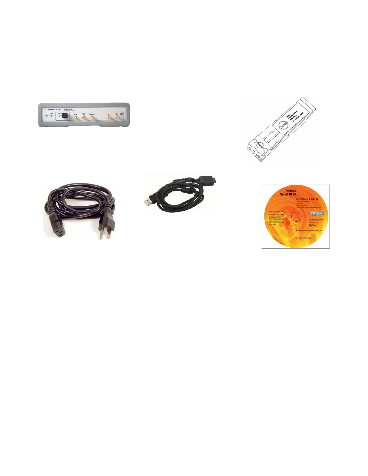
Agilent N5980A 3.125 GB/s
Serial BERT
Before you get started with the Serial BERT check if the shipment
package contains the following standard deliverables:
If the content is incomplete, if there is
mechanical damage, or if the
instrument does not work within its
specifications, notify the nearest Agilent
office. The Agilent office will arrange
for repair or replacement without
awaiting settlement.
SFP Loopback connector
Local Power Cord
USB Cable
(see CD content below).
CD
The CD content is:
Autorun.inf – If your PC supports autorun, this file starts the
installation.
dotnetfx.exe - This installs the latest Microsoft .Net Framework
2.0. This should be done in case .Net Framework 2.0 is not
already installed, and internet access is not available.
N5980A.msi – The Serial BERT installer package
Setup.exe – If your PC doesn’t support autorun, execute this file
to run the installation.
DoC.pdf - Declaration of Conformity
DataSheet.pdf – This document contains the product
specifications.
Presales_Presentation.pdf – Describes typical applications.
UserGuide.pdf – This document contains the details about how
to use the Serial BERT.
8 N5980A User Guide
Page 9
Getting Started
Connect the Instrument
In order to connect the Serial BERT let’s have a look at the Front and
the Rear Panels:
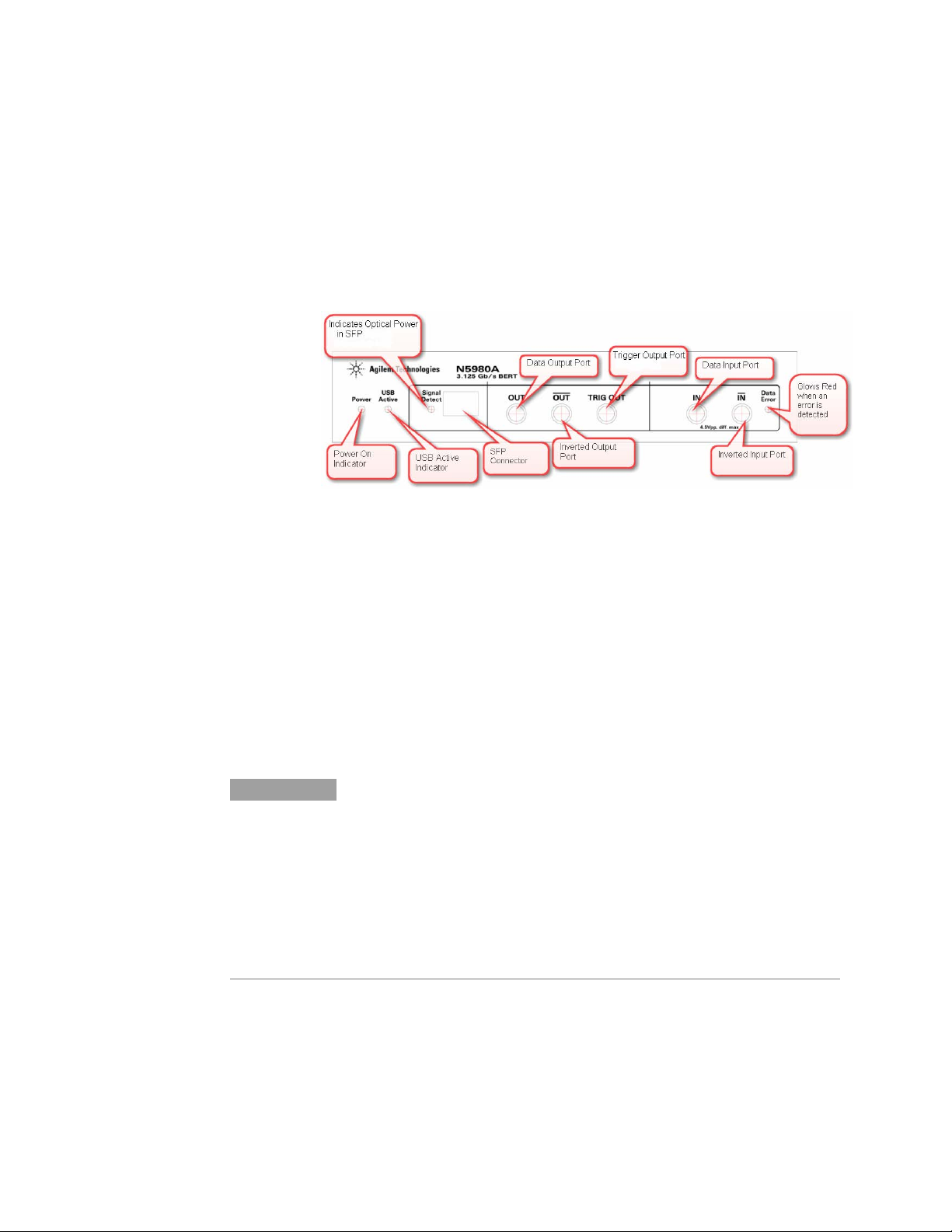
Front Panel
The Front Panel has LEDs, Data In/Out ports, and an SFP connector.
Figure 1 Front Panel
SFP
The Small Form Factor Pluggable interface (SFP) is an industry
standard daughter card used in networking devices. It interfaces a
network device with a networking cable. Typically SFP modules are
optical transceivers using multimode (850 nm), or single-mode (1310
nm, 1550nm) cabling.
An SFP loopback connector is part of the N5980A shipment delivery.
This connector is used for functional verification of the SFP port. It
has an internal loop from the SFP output to the SFP input signal.
NOTE
SFP compliant modules can be inserted into the SFP slot. While selecting
golden SFP modules observe the specifications of the selected device. Make
sure that the supported maximum PRBS length, and the maximum data rate
matches with the N5980A settings. Make sure that the wavelength of the SFP
module, and the cabling are identical, and that the optical power is within the
specified limit. To measure BER at the SFP input, select the Input “SFP
(Optical)” in the user interface.
N5980A User Guide 9
Page 10
Getting Started
LED
LEDs Function
Power LED
USB Active
Signal Detect
Data Error
Indicates power-on
Indicates that the instrument is currently being
used/controlled by the user software
Indicates the status of the Signal Detect line when the
inserted SFP module supports a Signal Detect Control line.
Usually this pin indicates whether the optical input power
is above or within the specified range.
Indicates that the error detector has detected bit errors
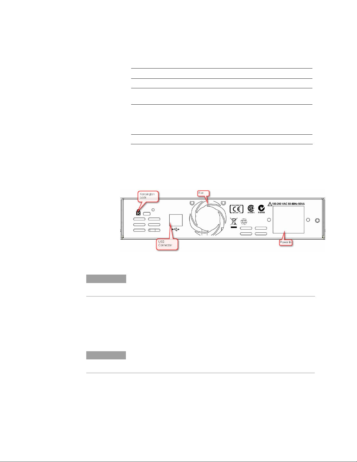
Rear Panel
The Rear Panel has the USB connector,the Power in, and the safety
symbols.
Figure 2 Rear Panel
NOTE
For proper ventilation keep the Serial BERT at a distance of 2 cm on both sides,
and 10 cm at the back.
To Connect N5980A
1 Connect the N5980A power cord at the rear panel Power In.
2 Connect the instrument, via USB, to the PC on which the User
Interface will be installed.
NOTE
Some USB hubs might decrease performance. If possible, directly connect the
N5980A to your PC.
10 N5980A User Guide
Page 11
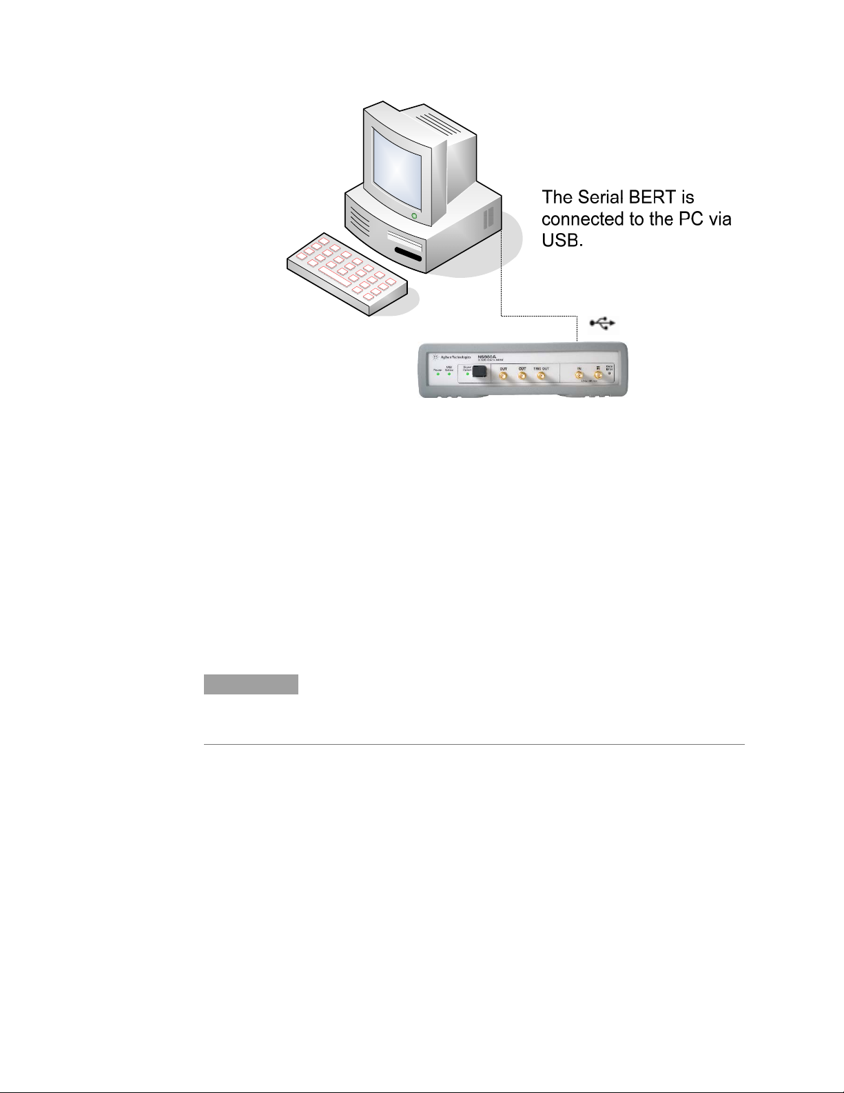
Getting Started
Figure 3 Serial BERT setup diagram
Install User Software for N5980A
The requirements for software installation:
Either Windows 2000 Service Pack 4, or Windows XP Service
Pack 2
Microsoft .NET Framework 2.0 is automatically downloaded from
the Microsoft download center during installation. Alternatively
dotnetfx.exe may be run from the installation CD in order to
install the Microsoft .Net Framework 2.0. This step should be
executed in case .Net Framework 2.0 is not already installed on
the computer, or the available internet connection is slow.
NOTE
To execute the User Software, Microsoft .NET Framework 2.0 is required.
N5980A User Guide 11
Page 12
Getting Started
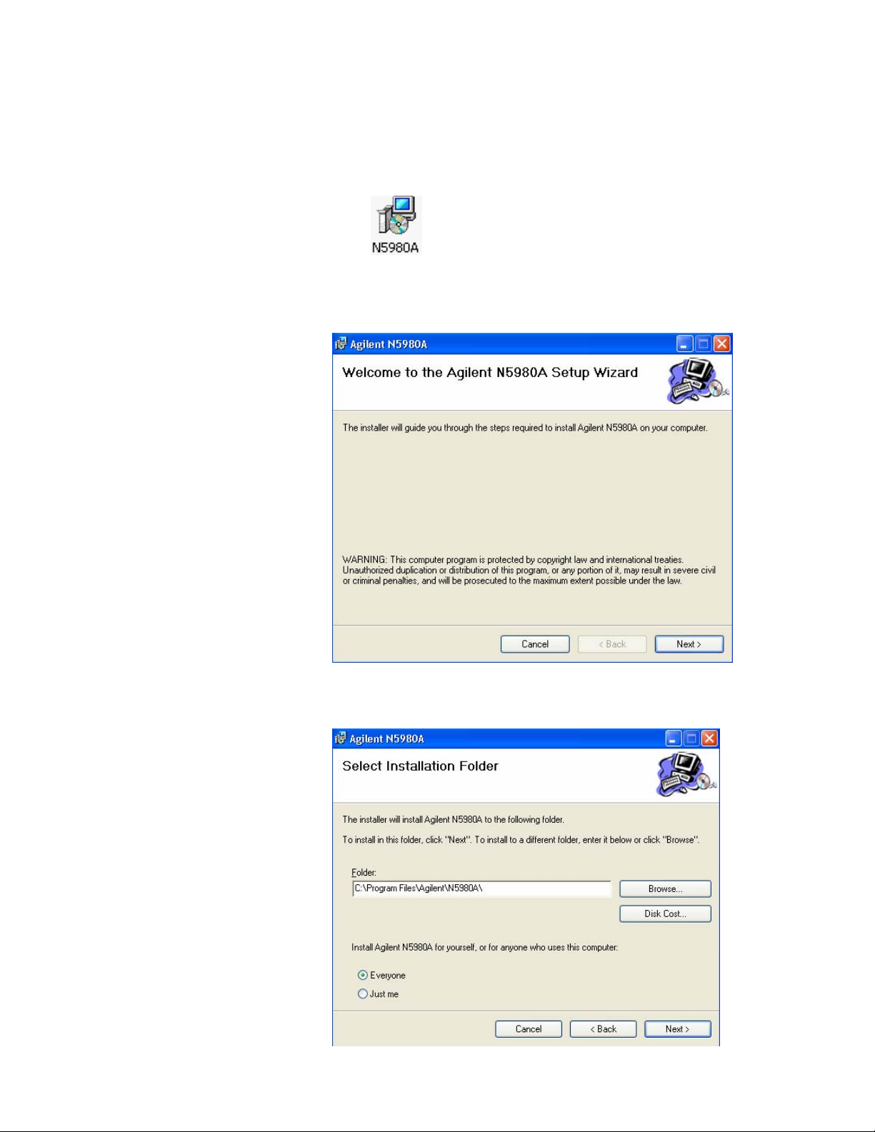
To Install the User Software for N5980A
1 Insert the CD in the PC’s CD Drive.
2 Double-click
Displays the Welcome screen.
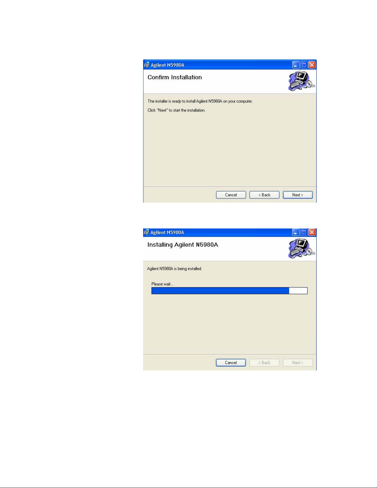
3 The Installer guides you through the installation process.
12 N5980A User Guide
Page 13
Getting Started
Select the folder in which N5980A will be saved.
N5980A User Guide 13
Page 14
Getting Started
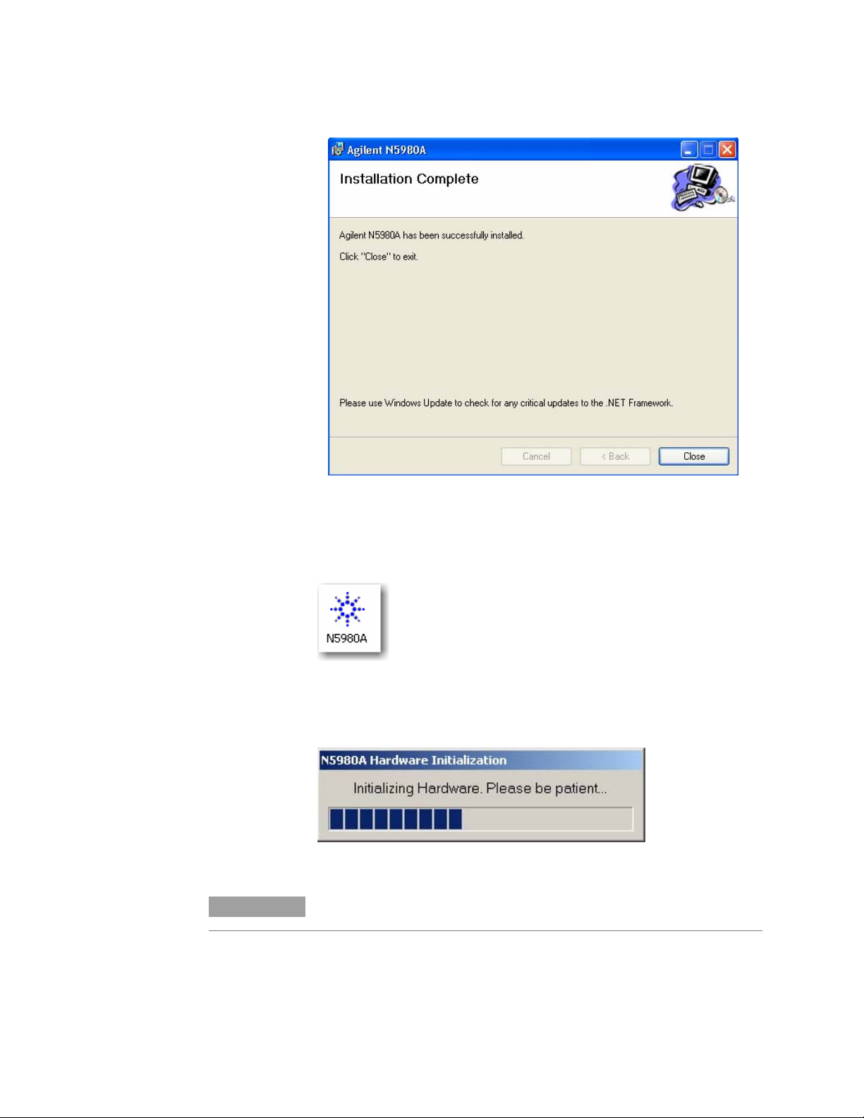
After the installation is completed, click Finish to close the installer.
To Access N5980A
To launch N5980A, go to Program File and click on:
If there is a N5980A connected to the PC via USB, and the User
Software is installed, then the following screen appears:
NOTE
Typical Hardware Initialization duration is between 3 to 5 minutes.
14 N5980A User Guide
Page 15

Getting Started
Upon completion of Hardware Initialization, the User Interface starts
and the following window appears.
Demo Offline
In Demo Offline mode N5980A need not be connected to the PC. The
connection dialog looks like the screen below.
Click Demo (Offline) to start the offline version of the GUI.
NOTE
Before disconnecting the USB cable, or powering down the instrument, make
sure you have closed the User Software.
.
N5980A User Guide 15
Page 16

Operating N5980A with the User Interface
3 Operating N5980A with the User Interface
Introduction
The graphical user interface runs on the PC, and the screen is
divided into two areas; one for setting parameters, and the other for
viewing results.
The Setting Parameters area of the screen has options for setting
parameters like Data Rate, Data Pattern and so on. The Viewing
Results area of the screen runs the test, and displays the results.
The User Software operates in two modes, Standard Mode and
Advanced Mode.
In Standard Mode you can modify the basic instrument setting,
and view the results.
In Advaced Mode you can modify the detailed instrument
settings, and view all the results.
NOTE
For more details check the Reference for the User Interface
.
16 N5980A User Guide
Page 17

Operating N5980A with the User Interface
Running the BER Test
The User Software supports a quick pass/fail measurement, which is
generally used for testing the DUT in manufacturing. This
measurement allows you to count the number of bit errors during a
user specified gating time. The result of the measurement is
displayed as Gating Errors, Gating BER, and by a simple red (=fail)
/ green (=pass) color coding of the Gating BER bar.
1 To run the basic measurement, click on Start Gating Period or
F12.
2 In case you want to stop the running measurement, click on:
3 Once the measurement is complete, the results would appear as
follows:
NOTE
N5980A User Guide 17
The Gating Time can be modified in Advanced Mode.
Page 18

Operating N5980A with the User Interface
Setting the Instrument Parameters
N5980A has two (SFP and SMA) integrated Pattern Generators,
which can be adjusted to different parameters, for example, different
patterns or different error insertion rates.
The N5980A Error Detector has two (SFP and SMA) different
physical input ports, while only one input port can be analyzed at a
given time. The analyzed input can be selected with the User
Software.
There are two setting pages, Setup and Advanced.
Setup
In the Setup page you can change, the Data Rate, which applies for
the Pattern Generator, and the Error Detector ; Data Pattern and
Logic Level for the Pattern Generator; and Data Pattern and the
analyzed Input of the Error Detector.
1 The following options are under Data Rate; and XAUI
[3,125.00Mb/s] is the default data rate:
2 The Data Pattern of the Pattern Generator supports PRBS
polynoms, clock patterns, and K28.5 pattern. PRBS 2^23-1 is
the default pattern:
NOTE
Use the scroll bar to see the complete list of patterns provided.
3 Logic Level has two options, ECL [850mV], and LVDS [400mV].
ECL [850mV] is the default level.
4 Error Detector Pattern. For details refer to
5 Error Detector Input has two options, SMA [Electrical], and
SFP [Optical]. SMA [Electrical] is the default input for the
Error Detector.
Error Detector.
18 N5980A User Guide
Page 19

Operating N5980A with the User Interface
Advanced
To view the Advanced page, click on the File menu and enable the
Advanced Mode:
The Advanced page has the following settings:
In this page you can set SFP and SMA Data Patterns, Error Insertion
Rate, and also select Clock Trigger Output for the Generator. It also
gives the option for setting the Gating Time for the Error Detector.
N5980A User Guide 19
Page 20

Operating N5980A with the User Interface
Viewing the Results
There are two options for viewing the results, BER and Advanced
BER, as shown below.
BER displays Gating BER and the Elapsed Gating Time.
The Advanced BER page can be opened only when Advanced Mode
is enabled. See below:
In this page you can see the Gating Errors, Actual Errors , and the
Pattern that is currently being used by the Error Detector.
20 N5980A User Guide
Page 21

Reference for the User Interface
4 Reference for the User Interface
This section explains the measured parameters, and the display
options that are specific to these measurements. Additionally, some
information is provided to explain the theoretical background to
these measurements.
When N5980A is launched the following screen is displayed:
File Menu
The File menu has the following options.
Advanced Mode
The Advanced Mode allows you to change the settings, and view the
results in the Advanced, and the Advanced BER pages.
Store Setting
This saves the changes made to the setting. To enable this menu
option you need to store a setting first.
N5980A User Guide 21
Page 22
Reference for the User Interface
Store Setting As
This is used to store/recall any setting with a user selected filename.
The user selects a specific location, and file name to save the settings.
Recall Setting
This recalls the saved settings.
Factory Default Setting
Restores the factory default settings, and is useful when the user has
problems finding a defined instrument state.
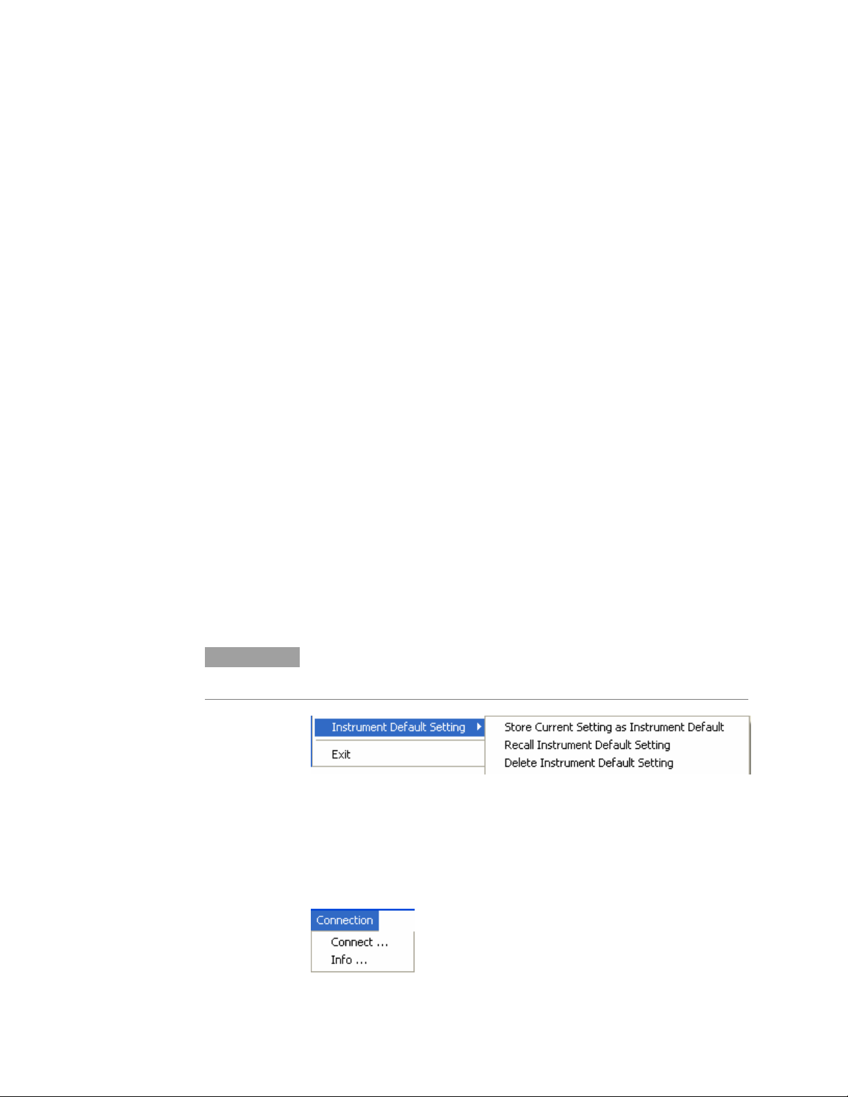
Instrument Default Setting
This is enabled only when Advanced Mode is on. The Instrument
Default Setting has three options related to the default setting.
Store Current Setting As Instrument Default, stores the
instruments current setting as default for this instrument. The
instrument default setting will be automatically applied whenever the
user software connects to the instrument. The instrument default
setting is stored individually for each instrument based on the
instrument's serial number.
Recall Instrument Default Setting, recalls the instrument's default
setting.
Delete Instrument Default Setting, deletes the instrument's default
setting.
If no User Setting exists, the factory default setting will be applied
when the User Software connects to the instrument.
NOTE
This setting is stored individually for each instrument by storing the instrument
serial number in the file name.
.
Exit
This closes the session with N5980A.
Connection Menu
This has the following options:
22 N5980A User Guide
Page 23

Reference for the User Interface
Connect
The Connect… option shows the Connection Dialog box.
NOTE
NOTE
If there are no instruments connected to the PC, then Connect button will be
disabled. If an instrument is connected, the user can connect to that
instrument.
In the Available Devices, the list of connected device will appear,
and the Connect button will be enabled.
Each PC can control only one N5980A.
In Remote Programming Setup, a port number can be selected for the
remote programming interface. The instrument will then be accessed
via a socket that connects the PC’s IP address and the chosen port
number.
Refresh updates the list of Available Devices.
Selecting the connection launches the GUI, as shown below.
N5980A User Guide 23
Page 24

Reference for the User Interface
Help Menu
Info
This option provides the following information.
Error Indicators
The Help Menu has the following information.
About gives you the Software details.
The GUI screen contains the Error Indicator:
There are two indicators and a BER bar, see the screen above. These
indicators inform you about the following errors:
• Bit error in the data stream
• Loss of pattern synchronization
• Complete loss of data
24 N5980A User Guide
Page 25

Reference for the User Interface
BER Bar
The BER bar displays the BER calculated during a period of 200 ms.
Error
This indicator turns red when errors are detected.
Stable errors are caused by the error add function: it turns
SFP/SMA Error Insertion Rate off.
Variable and high errors may be caused by faulty
connectors/cables. BERT connected to your device shows:
Stable or variable errors caused by your device. Correct the
problems with your device.
If the problems are not clear, then accumulate measurement
data and analyze the results.
Sync Loss
This indicator turns red when the measured BER is higher than the
sync threshold of 0.1.
The ED pattern does not match the incoming data pattern.
Patterns have lost sync.
The device connected to the BERT has inverted the data pattern.
The device has changed the data pattern.
NOTE
Error Detector can sync only PRBS patterns. Clock patterns cannot be measured
by the error detector, and will result in loss of synchronization.
N5980A User Guide 25
Page 26

Reference for the User Interface
Setup and Advanced Tab
Setup
General
Data Rate:
There are different data rates in the drop down list. These rates are
common to the Generator, and the Error Detector.
The following screen lists the available Data Rates.
Generator
Data Pattern:
There are different patterns available, for example, PRBS patterns,
Clock patterns, and K28.5 pattern.
NOTE
The drop down screen below lists the available patterns. To view all the
patterns use the scroll bar.
Level:
There are two levels provided, the ECL and the LVDS.
26 N5980A User Guide
Page 27

Reference for the User Interface
Error Detector
Data Pattern:
The Error Detector (ED) has a built in CDR for automatic clock
recovery, and phase alignment. The ED also performs automatic
polarity correction when required. Additionally it can detect the
incoming PRBS. The input for the Data Pattern has two options, SMA
[Electrical], and SFP [Optical]. SMA [Electrical] is the default input
for the Error Detector.
Automatic
SFP (Optical
Generator)
SMA (Electrical
Generator)
PRBS 2^7-1
PRBS 2^15-1
PRBS 2^23-1
PRBS 2^31-1
Error Detector determines the incoming data stream
automatically. The supported data streams are:
PRBS 2^7-1
PRBS 2^15-1
PRBS 2^23-1
PRBS 2^31-1
The data pattern is taken from the current setting on the SFP
generator output.
The data pattern is taken from the current setting on the SMA
generator output.
A PRBS 2^7-1 is used for pattern synchronization.
A PRBS 2^15-1 is used for pattern synchronization.
A PRBS 2^23-1 is used for pattern synchronization.
A PRBS 2^31-1 is used for pattern synchronization.
Input:
There are two inputs to the Error Detector, the SMA (Electrical),
and the SFP (Optical).
Advanced
In the Advanced tab you can separately set the Data Patterns, and
Error insertion for the SFP and SMA generator outputs.
Generator
SFP Data Pattern:
In this drop down list you have the same set of patterns, as in the
setup page, to select from. The selected pattern will affect the SFP
output.
SMA Data Pattern:
In this drop down list you have the same set of patterns to select
from. The selected pattern will affect the SMA output.
N5980A User Guide 27
Page 28

Reference for the User Interface
NOTE
NOTE
On the advanced page the SFP and the SMA Data pattern can be adjusted
independently.
SFP Error Insertion Rate:
This drop down list gives a set of Error Insertion Rates that can be
inserted for the SFP output.
SMA Error Insertion Rate:
This drop down list gives a set of Error Insertion Rates that can be
inserted for the SFP output.
Both the lists contain the same set of Error Insertion Rates. The following
screen shows this list.
Trigger Out:
The Trigger Out lists a set of clock triggers. The list is shown below:
Error Detector
Gating Time:
The Gating Time can be set in terms of hour, minute, and seconds.
The maximum gating time is 168 hours 59 minutes and 59 seconds.
BER and Advanced BER Tab
BER
Gating BER Bar
This BER Bar indicates the Bit Error during the Gating Period. Once
the Gating Period is complete this Bar turns green if the test passes
(Gating BER is 0.0), and turns red if the test fails (Gating BER > 0.0).
28 N5980A User Guide
Page 29

Reference for the User Interface
The screenshot below shows the Gating BER Bar.
Elapsed Gating Time
This bar shows the gating time while the test runs.
Before the test begins this bar is empty as shown below:
And after the gating time is complete this bar appears as shown
below:
Advanced BER
This page contains Gating Error, Actual Error, Error Detector Pattern
Gating BER Bar, and Elapsed Gating Time.
Gating Errors
This indicates the number of Errors that occurred during the gating
time.
Actual Errors
This indicates the number of errors that occurred during the last
update interval of 200ms.
Error Detector Pattern
This displays the pattern that is currently being used by the Error
Detector.
N5980A User Guide 29
Page 30

Programming Reference
5 Programming Reference
Introduction
The SCPI commands represent the instrument’s advanced analysis,
and pattern generation features that can be controlled from within
the remote programs.
Programming can only be done using raw Windows Sockets. The
remote programming language is close to SCPI, but it’s without a full
featured SCPI parser.
Thus N5980A is not SCPI1997 compliant.
The missing standard SCPI features:
Status handling/registers
Support of short and long form of SCPI commands (the
commands must be sent exactly like noted below)
No default suffixes.
Only a few of the standard commands (e.g. *OPC is missing)
The commands must always be complete, even for the second
parameter that belongs to the same root node inside a transaction.
Example:
SCPI allows: :SOUR1:PATT PRBS7;EADD ONCE
N5980A needs: :SOUR1:PATT PRBS7; :SOUR1:PATT:EADD
ONCE
See
Sample Code
as an example to control the N5980A from within a remote program.
Common Command Summary
*TST?
*OPC?
*RST
*IDN?
*OPT?
Agilent N5980A Command Summary
:FREQ?
:FREQ
:MMEM:STOR:STAT
:MMEM:LOAD:STAT
:SYST:ERR?
:SOUR1:PATT
:SOUR1:PATT?
:SOUR1:PATT:EADD
:SOUR1:PATT:EADD:RATE?
:SOUR1:PATT:EADD:RATE
30 N5980A User Guide
Page 31

Programming Reference
:SOUR1:VOLT
:SOUR1:VOLT?
:SOUR2:PATT
:SOUR2:PATT?
:SOUR2:PATT:EADD
:SOUR2:PATT:EADD:RATE
:SOUR2:PATT:EADD:RATE?
:SOUR3:PATT?
:SOUR3:PATT
:SENS1:SYNC:TYPE
:SENS1:SYNC:TYPE?
:SENS1:PATT?
:SENS1:GATE:PER
:SENS1:GATE:PER?
:SENS1:FETC:ECO?
:SENS1:FETC:ECO:DELT?
:SENS1:FETC:ERAT?
:SENS1:FETC:ERAT:DELT?
:SENS1:INP
:SENS1:INP?
:SENS1:GATE:STAT
:SENS1:GATE:STAT?
SCPI Instrument Command List- Reference
The following reference section lists the instrument commands. The
commands are described, and in addition the available attributes for
certain commands are also described.
Common Commands
ID Query
Syntax *IDN?
Description Reads the identification string from the instrument. The
*IDN?
format of the identification string is:
Agilent Technologies,Product Number,Serial
Number,Revision Info
Product Number is currently N5980A.
Serial Number is read from the instrument hardware (0 if
offline).
Revision Info consists of:
Application Revision (Microsoft w.x.y.z format)
Instruments Firmware Revision (Major.Minor, 0 if
offline)
Hardware Revision (0 if offline)
N5980A User Guide 31
Page 32

Programming Reference
Read error queue
Syntax :SYST:ERR?
Description Reads one error from the instruments error queue.
Load factory default setting
Syntax *RST
Description Discards the current instrument setting, and loads the
Operation complete
Syntax *OPC?
Description Returns 1 when all pending commands have been
Option Query
Syntax *OPT?
Description Reports all instrument options. Currently the instrument
:SYST:ERR?
*RST
reset/default setting.
*OPC?
executed. Blocks until all pending commands are executed.
*OPT?
does not have any option, so this query reports 0.
Output: always return 0
Self test
Syntax *TST?
Description Performs the instrument selftest. Returns 0 in case of
*TST?
success and 1 in case of errors during the selftest. Error
messages that are discovered during the selftest will be
stored in the instrument’s error queue.
32 N5980A User Guide
Page 33

Programming Reference
Store current setting
Syntax :MMEM:STOR:STAT “filename”
Description Stores the current setting into the specified file. If a file
Recall setting
Syntax :MMEM:LOAD:STAT “filename”
Description Loads stored instrument setting from the given file.
All Channels
Datarate
Syntax :FREQ?
Description Either sets or gets the instrument’s datarate. The datarate
Available Data Rates
:MMEM:STOR:STAT “filename”
with the same name already exists, then this file will be
overwritten.
:MMEM:LOAD:STAT “filename”
:FREQ
:FREQ FE
OC3|OC12|OC48|OC48FEC|FC1|FC2|GBE1|XAUI
always applies to all the channels (electrical out, optical out,
clock out, and error detector input).
Name Frequency Parameter
Fast Ethernet 125.00Mb/s FE
OC-3 155.52Mb/s OC3
OC-12 622.08Mb/s OC12
OC-48 2.48832Gb/s OC48
OC-48 with
FEC
1 x FC 1.0625Gb/s FC1
2 x FC 2.125Gb/s FC2
Gigabit
Ethernet
XAUI 3.125Gb/s XAUI
2.666Gb/s OC48FEC
1.25Gb/s GBE1
N5980A User Guide 33
Page 34

Programming Reference
SMA Output (Electrical Generator)
The SMA output is accessed via the root node :SOUR1
Pattern
:SOUR1:PATT
Syntax :SOUR1:PATT?
:SOUR1:PATT
PRBS7|PRBS15|PRBS23|PRBS31|CLK2|CLK4|CLK8|CLK10|CLK16
|CLK20|K28_5
Description Either sets or gets the pattern of the SMA output.
Available
Patterns
Name Parameter
PRBS 2^7-1 PRBS7
PRBS 2^15-1 PRBS15
PRBS 2^23-1 PRBS23
PRBS 2^31-1 PRBS31
Clock / 2 CLK2
Clock / 4 CLK4
Clock / 8 CLK8
Clock / 10 CLK10
Clock / 16 CLK16
Clock / 20 CLK20
K28.5 K28_5
34 N5980A User Guide
Page 35

Programming Reference
Error Insertion
The error insertion is capable to enforce a given error ratio, and to
add single errors into the data stream. Both are available in parallel.
Insertion Rate
Description Either sets or gets the error insertion rate. Only the listed
Available Insertion
Add Single Error
Description Adds a single error to the generated data stream. This is
:SOUR1:PATT:EADD:RATE
Syntax :SOUR1:PATT:EADD:RATE?
:SOUR1:PATT:EADD:RATE NR3
error rates are available. If another value is specified while
sending the command, the error rate will be rounded to the
next available value.
Rate
Inserted error rate Parameter
None 0
1e-3 1e-3
1e-4 1e-4
1e-5 1e-5
1e-6 1e-6
1e-7 1e-7
1e-8 1e-8
1e-9 1e-9
:SOUR1:PATT:EADD
Syntax :SOUR1:PATT:EADD ONCE
available even if the cyclic error insertion is active.
Output Level
Syntax :SOUR1:VOLT?
Description This either sets or gets the output level. The output is
Available Output
Levels
:SOUR1:VOLT
:SOUR1:VOLT ECL|LVDS
always AC. Specifying the output level actually changes
only the amplitude of the generated electrical signal.
Parameter Level
ECL 850mV
LVDS 400mV
N5980A User Guide 35
Page 36

Programming Reference
SFP Output (Optical Generator)
The SFP output is accessed via the root node :SOUR2
Pattern
:SOUR2:PATT
Syntax :SOUR2:PATT?
:SOUR2:PATT
PRBS7|PRBS15|PRBS23|PRBS31|CLK2|CLK4|CLK8|CLK10|CLK16
|CLK20|K28_5
Description Either sets or gets the pattern of the SFP output.
Available
Patterns
Name Parameter
PRBS 2^7-1 PRBS7
PRBS 2^15-1 PRBS15
PRBS 2^23-1 PRBS23
PRBS 2^31-1 PRBS31
Clock / 2 CLK2
Clock / 4 CLK4
Clock / 8 CLK8
Clock / 10 CLK10
Clock / 16 CLK16
Clock / 20 CLK20
K28.5 K28_5
36 N5980A User Guide
Page 37

Programming Reference
Error Insertion
The error insertion is capable to enforce a given error ratio, and to
add single errors into the data stream. Both are available in parallel.
Insertion Rate
Description Either sets or gets the error insertion rate. Only the listed
Available Insertion
Add Single Error
Description Adds a single error to the generated data stream. This is
:SOUR2:PATT:EADD:RATE
Syntax :SOUR2:PATT:EADD:RATE?
:SOUR2:PATT:EADD:RATE NR3
error rates are available. If another value is specified while
sending the command, the error rate will be rounded to the
next available value.
Rate
Syntax :SOUR2:PATT:EADD ONCE
Inserted error rate Parameter
None 0
1e-3 1e-3
1e-4 1e-4
1e-5 1e-5
1e-6 1e-6
1e-7 1e-7
1e-8 1e-8
1e-9 1e-9
:SOUR2:PATT:EADD ONCE
available even if the cyclic error insertion is active.
N5980A User Guide 37
Page 38

Programming Reference
Trigger Output
The trigger output is accessible via the root node :SOUR3
Pattern
:SOUR3:PATT
Syntax :SOUR3:PATT?
:SOUR3:PATT CLK2|CLK4|CLK8|CLK10|CLK16|CLK20
Description Either sets or gets the pattern of the trigger output.
Available Patterns
Name Parameter
Clock / 2 CLK2
Clock / 4 CLK4
Clock / 8 CLK8
Clock / 10 CLK10
Clock / 16 CLK16
Clock / 20 CLK20
Error Detector
The Error Detector channel is accessed via the root node :SENS1
Detected Pattern
Syntax :SENS1:PATT?
Description Gets the pattern that is currently used on the Error
Response
:SENS1:PATT?
Detector to compare it with the incoming data stream. This
might change when the Error Detector detects a very high
error ratio, and tries to synchronize with the incoming data.
Error Detector Pattern Response
PRBS 2^7-1 PRBS7
PRBS 2^15-1 PRBS15
PRBS 2^23-1 PRBS23
PRBS 2^31-1 PRBS31
Error Detector has lost pattern
synchronization.
UNKNOWN
38 N5980A User Guide
Page 39

Programming Reference
Synchronization mode
Synchronization
:SENS1:SYNC:TYPE
Syntax :SENS1:SYNC:TYPE
Description Either sets or gets the synchronization type. The
Available
Types
AUTO|SFP|SMA|PRBS7|PRBS15|PEBS23|PRBS31
:SENS1:SYNC:TYPE?
synchronization type defines which patterns will be used to
synchronize when a synchronization loss is detected by the
Error Detector.
Parameter Synchronization behavior
AUTO The Error Detector will use all available
patterns to synchronize with the incoming
data stream.
SFP The Error Detector will use only the
pattern that is set for the SFP output.
SMA The Error Detector will only use the
pattern that is set for the SMA output.
PRBS7 The Error Detector will only use a PRBS
2^7-1 data stream.
PRBS15 The Error Detector will only use a PRBS
2^15-1 data stream.
PRBS23 The Error Detector will only use a PRBS
2^23-1 data stream.
PRBS31 The Error Detector will only use a PRBS
2^31-1 data stream.
Actual Bit Error Rate
Syntax :SENS1:FETC:ERAT:DELT?
Description Gets the bit error ratio of the last update interval (approx
:SENS1:FETC:ERAT:DELT
200ms).
Actual Number of Errors
Syntax :SENS1:FETC:ECO:DELT?
Description Gets the number of errors that have been counted during
:SENS1:FETC:ECO:DELT
the last update interval (approx. 200ms).
N5980A User Guide 39
Page 40

Programming Reference
Gating Time
Syntax :SENS1:GATE:PER?
Description Either gets or sets the duration of the gating interval. The
Gating Bit Error Rate
Syntax :SENS1:FETC:ERAT?
Description Gets the bit error ration that is captured during the gating
Gating Number of Errors
Syntax :SENS1:FETC:ECO?
Description Gets the number of errors that have been counted during
:SENS1:GATE:PER
:SENS1:GATE:PER integer
allowed range for the gating time is 1s to 608399s (168
hours, 59 minutes, 59 seconds). The gating time is always
in seconds. Fractional seconds are not supported, and will
be rounded to the closest time in seconds.
:SENS1:FETC:ERAT
interval. This value might/will change while the gating is in
progress, and will freeze at the end of the gating interval.
:SENS1:FETC:ECO
the gating interval. This value might/will change while
gating is in progress, and will freeze at the end of the
gating interval.
Start Gating
Abort Gating
:SENS1:GATE:STAT 1
Syntax :SENS1:GATE:STAT 1|ON
Description Starts a new gating period. This command will be ignored if
a gating period is already in progress.
:SENS1:GATE:STAT 0
Syntax :SENS1:GATE:STAT 0|OFF
Description This command aborts the currently active gating period
immediately. It will be ignored if the gating is not in
progress.
40 N5980A User Guide
Page 41

Programming Reference
Gating Progress
Input Selection
:SENS1:GATE:STAT
Syntax :SENS1:GATE:STAT?
Description Requests the current state of the gating interval. It will
return 1 while the gating is in progress and 0 if the gating
is finished/ inactive. It is guaranteed that the very first
:SENS1:GATE:STAT? query after the start of the gating
period will report a valid state of the gating progress. There
is no need to capture 0-1-0 transitions of the gating
progress.
SENS1:INP
Syntax SENS1:INP SFP|SMA
Description Selects the input for the error detector.
N5980A User Guide 41
Page 42

Programming Reference
Sample Code
The following example code shows how to control the N5980A from
within a remote program. The example code is implemented in C#.
The code snippets show the required code that needs to be added to a
user program.
It implements a class N5980A in the namespace N5980AExample that
allows communication with the N5980A user software.
using System;
using System.Collections.Generic;
using System.Text;
using System.Net;
using System.Net.Sockets;
using System.Windows.Forms;
namespace TBertExample
{
class N5980A
{
/// <summary>
/// Holds the input buffer when reading from the socket.
/// </summary>
byte[] bufferin = new byte[64 * 1024];
/// <summary>
/// Holds the TcpClient that is used to establish the
/// remote connection.
/// </summary>
TcpClient m_Client = null;
/// <summary>
/// Holds the NetworkStream that provides the communication
link.
/// </summary>
NetworkStream m_Stream = null;
/// <summary>
/// Connect to the instrument with the given hostname and
/// port number. Both values can be retrieved by the
/// Connection -> Info... menu item in the N5980A software
/// </summary>
/// <param name="host">Hostname of the PC that executes
/// the N5980A software.</param>
/// <param name="port">Port number of the software instance
/// to communicate with.</param>
public void Connect(string host, int port)
{
try
{
// resolve address of the given hostname
IPHostEntry ipHostEntry = Dns.Resolve(host);
IPAddress ipAddress = ipHostEntry.AddressList[0];
// create TcpClient and connect it to the instrument
m_Client = new TcpClient();
m_Client.Connect(new IPEndPoint(ipAddress, port));
m_Stream = m_Client.GetStream();
}
catch (Exception e)
{
MessageBox.Show(e.Message, "Connect");
}
}
/// <summary>
/// Close the connection with the N5980A software.
42 N5980A User Guide
Page 43

Programming Reference
/// </summary>
public void Disconnect()
{
if (m_Client != null)
m_Client.Close();
}
/// <summary>
/// Write to a SCPI command to a network socket and return
the
/// response if it was a query.
/// </summary>
/// <param name="s">SCPI command to be written to the
socket</param>
/// <returns>Response of the instrument or an empty string
/// if there is no response.</returns>
public string Send(string s)
{
string response = "";
int i;
// Write the string to the network socket
byte[] bufferout = new byte[s.Length + 1];
for (i = 0; i < s.Length; i++)
bufferout[i] = (byte)s[i];
bufferout[s.Length] = (byte)'\n';
m_Stream.Write(bufferout, 0, bufferout.Length);
// If the string containes a '?', then it is a query and
// the response nneds to be read from the instrument
if (s.IndexOf('?') != -1)
{
// Read resonse from network stream
int numRead = m_Stream.Read(bufferin, 0,
bufferin.Length);
// if the response contained any bytes, then convert
them
// to a valid string
if (numRead > 0)
{
StringBuilder sb = new StringBuilder();
for (i = 0; i < numRead; i++)
sb.Append((char)bufferin[i]);
// make sure that all kind of terminators are
// reported as \r\n
sb.Append("\r\n");
response = sb.ToString().Trim(new char[] { '\r', '\n'
});
if (response.IndexOf("\r\n") != -1)
response = response.Replace("\r\n", "\n");
if (response.IndexOf("\r") != -1)
response = response.Replace("\r", "\r");
if (response.IndexOf("\n") != -1)
response = response.Replace("\n", "\r\n");
}
}
return response;
}
}
}
Communicate with the instrument
Given the class above, the communication with the instrument
can be done like this:
using System;
using System.Collections.Generic;
namespace TBertExample
{
static class Program
N5980A User Guide 43
Page 44

Programming Reference
{
/// <summary>
/// The main entry point for the application.
/// </summary>
[STAThread]
static void Main()
{
N5980A instrument = new N5980A();
// Connect to the N5980A software running on the same
// PC as this program and that is using port number 5025
instrument.Connect("localhost", 5025);
// set the data rate to OC-3
instrument.Send(":freq OC3");
// read the data rate
string response = instrument.Send(":freq?");
// Close the socket => disconnect from the instrument
instrument.Disconnect();
// From here on, it is no longer possible to communicate
with the
// instrument.
}
}
}
44 N5980A User Guide
 Loading...