

Agilent Technologies DSO5054A, DSO5012A, DSO5034A, DSO5032A, DSO5052A Programmer's Manual
...Page 1

Agilent InfiniiVision
5000 Series
Oscilloscopes
Programmer's Guide
A
Page 2

Notices
© Agilent Technologies, Inc. 2007-2008
No part of this manual may be reproduced
in any form or by any means (including
electronic storage and retrieval or translation into a foreign language) without prior
agreement and written consent from Agilent Technologies, Inc. as governed by
United States and international copyright
laws.
Trademarks
Microsoft®, MS-DOS®, Windows®, Windows 2000®, and Windows XP® are U.S.
registered trademarks of Microsoft Corporation.
Adobe®, Acrobat®, and the Acrobat
Logo® are trademarks of Adobe Systems
Incorporated.
Manual Part Number
Version 05.15.0000
Edition
July 31, 2008
Available in electronic format only
Agilent Technologies, Inc.
1900 Garden of the Gods Road
Colorado Springs, CO 80907 USA
Warranty
The material contained in this document is provided “as is,” and is subject to being changed, without notice,
in future editions. Further, to the maximum extent permitted by applicable
law, Agilent disclaims all warranties,
either express or implied, with regard
to this manual and any information
contained herein, including but not
limited to the implied warranties of
merchantability and fitness for a particular purpose. Agilent shall not be
liable for errors or for incidental or
consequential damages in connection
with the furnishing, use, or performance of this document or of any
information contained herein. Should
Agilent and the user have a separate
written agreement with warranty
terms covering the material in this
document that conflict with these
terms, the warranty terms in the separate agreement shall control.
Technology Licenses
The hardware and/or software described in
this document are furnished under a
license and may be used or copied only in
accordance with the terms of such license.
Restricted Rights Legend
agency regulation or contract clause. Use,
duplication or disclosure of Software is
subject to Agilent Technologies’ standard
commercial license terms, and non-DOD
Departments and Agencies of the U.S. Government will receive no greater than
Restricted Rights as defined in FAR
52.227-19(c)(1-2) (June 1987). U.S. Government users will receive no greater than
Limited Rights as defined in FAR 52.227-14
(June 1987) or DFAR 252.227-7015 (b)(2)
(November 1995), as applicable in any
technical data.
Safety Notices
CAUTION
A CAUTION notice denotes a hazard. It calls attention to an operating procedure, practice, or the like
that, if not correctly performed or
adhered to, could result in damage
to the product or loss of important
data. Do not proceed beyond a
CAUTION notice until the indicated
conditions are fully understood and
met.
WARNING
A WARNING notice denotes a
hazard. It calls attention to an
operating procedure, practice, or
the like that, if not correctly performed or adhered to, could result
in personal injury or death. Do not
proceed beyond a WARNING
notice until the indicated conditions are fully understood and met.
If software is for use in the performance of
a U.S. Government prime contract or subcontract, Software is delivered and
licensed as “Commercial computer software” as defined in DFAR 252.227-7014
(June 1995), or as a “commercial item” as
defined in FAR 2.101(a) or as “Restricted
computer software” as defined in FAR
52.227-19 (June 1987) or any equivalent
Page 3

In This Book
This book is your guide to programming the 5000 Series oscilloscopes:
Table 1 InfiniiVision 5000 Series Oscilloscope Models
Channels Input Bandwidth (Maximum Sample Rate)
500 MHz (4 GSa/s) 300 MHz (2 GSa/s) 100 MHz (2 GSa/s)
4 analog DSO5054A DSO5034A DSO5014A
2 analog DSO5052A DSO5032A DSO5012A
The first few chapters describe how to set up and get started:
• Chapter 1, "What's New" on page 19, describes programming command
changes in the latest version of oscilloscope software.
• Chapter 2, "Setting Up" on page 27, describes the steps you must take
before you can program the oscilloscope.
• Chapter 3, "Getting Started" on page 37, gives a general overview of
oscilloscope program structure and shows how to program the
oscilloscope using a few simple examples.
• Chapter 4, "Commands Quick Reference" on page 51, is a brief listing of
the 5000 Series oscilloscope commands and syntax.
The next chapters provide reference information:
• Chapter 5, "Commands by Subsystem" on page 89, describes the set of
commands that belong to an individual subsystem and explains the
function of each command. Command arguments and syntax are
described. Some command descriptions have example code.
• Chapter 6, "Commands A- Z" on page 477, contains an alphabetical
listing of all command elements.
• Chapter 7, "Obsolete and Discontinued Commands" on page 501,
describes obsolete commands which still work but have been replaced
by newer commands and discontinued commands which are no longer
supported.
• Chapter 8, "Error Messages" on page 545, lists the instrument error
messages that can occur while programming the oscilloscope.
The command descriptions in this reference show upper and lowercase
characters. For example, :AUToscale indicates that the entire command
name is :AUTOSCALE. The short form, :AUT, is also accepted by the
oscilloscope.
Then, there are chapters that describe programming topics and conceptual
information in more detail:
• Chapter 9, "Status Reporting" on page 553, describes the oscilloscope's
status registers and how to check the status of the instrument.
Agilent InfiniiVision 5000 Series Oscilloscopes Programmer's Guide 3
Page 4

• Chapter 10, "Synchronizing Acquisitions" on page 575, describes how to
wait for acquisitions to complete before querying measurement results
or performing other operations with the captured data.
• Chapter 11, "More About Oscilloscope Commands" on page 585, contains
additional information about oscilloscope programming commands.
Finally, there is a chapter that contains programming examples:
• Chapter 12, "Programming Examples" on page 607.
See Also • For more information on using the SICL, VISA, and VISA COM libraries
in general, see the documentation that comes with the Agilent IO
Libraries Suite.
• For information on controller PC interface configuration, see the
documentation for the interface card used (for example, the Agilent
82350A GPIB interface).
• For information on oscilloscope front-panel operation, see the User's
Guide.
• For detailed connectivity information, refer to the Agilent Technologies
USB/LAN/GPIB Connectivity Guide. For a printable electronic copy of
the Connectivity Guide, direct your Web browser to "www.agilent.com"
and search for "Connectivity Guide".
• For the latest versions of this and other manuals, see:
"http://www.agilent.com/find/5000manual"
4 Agilent InfiniiVision 5000 Series Oscilloscopes Programmer's Guide
Page 5

Contents
1 What's New
2 Setting Up
In This Book 3
What's New in Version 5.15 20
What's New in Version 5.10 22
What's New in Version 5.00 23
What's New in Version 4.10 25
Version 4.00 at Introduction 26
Step 1. Install Agilent IO Libraries Suite software 28
Step 2. Connect and set up the oscilloscope 29
Using the USB (Device) Interface 29
Using the LAN Interface 29
Using the GPIB Interface 30
Step 3. Verify the oscilloscope connection 31
3 Getting Started
Basic Oscilloscope Program Structure 38
Initializing 38
Capturing Data 38
Analyzing Captured Data 39
Agilent InfiniiVision 5000 Series Oscilloscopes Programmer's Guide 5
Page 6

Programming the Oscilloscope 40
Referencing the IO Library 40
Opening the Oscilloscope Connection via the IO Library 41
Initializing the Interface and the Oscilloscope 41
Using :AUToscale to Automate Oscilloscope Setup 42
Using Other Oscilloscope Setup Commands 42
Capturing Data with the :DIGitize Command 43
Reading Query Responses from the Oscilloscope 45
Reading Query Results into String Variables 46
Reading Query Results into Numeric Variables 46
Reading Definite-Length Block Query Response Data 46
Sending Multiple Queries and Reading Results 47
Checking Instrument Status 48
Other Ways of Sending Commands 49
Tel ne t S oc ke ts 49
Sending SCPI Commands Using Browser Web Control 49
4 Commands Quick Reference
Command Summary 52
Syntax Elements 85
Number Format 85
<NL> (Line Terminator) 85
[ ] (Optional Syntax Terms) 85
{ } (Braces) 85
::= (Defined As) 85
< > (Angle Brackets) 86
... (Ellipsis) 86
n,..,p (Value Ranges) 86
d (Digits) 86
Quoted ASCII String 86
Definite-Length Block Response Data 86
5 Commands by Subsystem
Common (*) Commands 91
*CLS (Clear Status) 95
*ESE (Standard Event Status Enable) 96
*ESR (Standard Event Status Register) 98
*IDN (Identification Number) 100
*LRN (Learn Device Setup) 101
*OPC (Operation Complete) 102
6 Agilent InfiniiVision 5000 Series Oscilloscopes Programmer's Guide
Page 7

*OPT (Option Identification) 103
*RCL (Recall) 104
*RST (Reset) 105
*SAV (Save) 108
*SRE (Service Request Enable) 109
*STB (Read Status Byte) 111
*TRG (Trigger) 113
*TST (Self Test) 114
*WAI (Wait To Continue) 115
Root (:) Commands 116
:AER (Arm Event Register) 119
:AUToscale 120
:AUToscale:AMODE 122
:AUToscale:CHANnels 123
:BLANk 124
:CDISplay 125
:DIGitize 126
:HWEenable (Hardware Event Enable Register) 128
:HWERegister:CONDition (Hardware Event Condition Register) 130
:HWERegister[:EVENt] (Hardware Event Event Register) 132
:MERGe 134
:OPEE (Operation Status Enable Register) 135
:OPERegister:CONDition (Operation Status Condition Register) 137
:OPERegister[:EVENt] (Operation Status Event Register) 139
:OVLenable (Overload Event Enable Register) 141
:OVLRegister (Overload Event Register) 143
:PRINt 145
:RUN 146
:SERial 147
:SINGle 148
:STATus 149
:STOP 150
:TER (Trigger Event Register) 151
:VIEW 152
:ACQuire Commands 153
:ACQuire:AALias 155
:ACQuire:COMPlete 156
:ACQuire:COUNt 157
:ACQuire:DAALias 158
:ACQuire:MODE 159
:ACQuire:POINts 160
Agilent InfiniiVision 5000 Series Oscilloscopes Programmer's Guide 7
Page 8

:ACQuire:SEGMented:COUNt 161
:ACQuire:SEGMented:INDex 162
:ACQuire:SRATe 164
:ACQuire:TYPE 165
:CALibrate Commands 167
:CALibrate:DATE 168
:CALibrate:LABel 169
:CALibrate:STARt 170
:CALibrate:STATus 171
:CALibrate:SWITch 172
:CALibrate:TEMPerature 173
:CALibrate:TIME 174
:CHANnel<n> Commands 175
:CHANnel<n>:BWLimit 178
:CHANnel<n>:COUPling 179
:CHANnel<n>:DISPlay 180
:CHANnel<n>:IMPedance 181
:CHANnel<n>:INVert 182
:CHANnel<n>:LABel 183
:CHANnel<n>:OFFSet 184
:CHANnel<n>:PROBe 185
:CHANnel<n>:PROBe:ID 186
:CHANnel<n>:PROBe:SKEW 187
:CHANnel<n>:PROBe:STYPe 188
:CHANnel<n>:PROTection 189
:CHANnel<n>:RANGe 190
:CHANnel<n>:SCALe 191
:CHANnel<n>:UNITs 192
:CHANnel<n>:VERNier 193
:DISPlay Commands 194
:DISPlay:CLEar 196
:DISPlay:DATA 197
:DISPlay:LABel 199
:DISPlay:LABList 200
:DISPlay:PERSistence 201
:DISPlay:SOURce 202
:DISPlay:VECTors 203
:EXTernal Trigger Commands 204
:EXTernal:BWLimit 206
:EXTernal:IMPedance 207
8 Agilent InfiniiVision 5000 Series Oscilloscopes Programmer's Guide
Page 9

:EXTernal:PROBe 208
:EXTernal:PROBe:ID 209
:EXTernal:PROBe:STYPe 210
:EXTernal:PROTection 211
:EXTernal:RANGe 212
:EXTernal:UNITs 213
:FUNCtion Commands 214
:FUNCtion:CENTer 217
:FUNCtion:DISPlay 218
:FUNCtion:GOFT:OPERation 219
:FUNCtion:GOFT:SOURce1 220
:FUNCtion:GOFT:SOURce2 221
:FUNCtion:OFFSet 222
:FUNCtion:OPERation 223
:FUNCtion:RANGe 224
:FUNCtion:REFerence 225
:FUNCtion:SCALe 226
:FUNCtion:SOURce1 227
:FUNCtion:SOURce2 228
:FUNCtion:SPAN 229
:FUNCtion:WINDow 230
:HARDcopy Commands 231
:HARDcopy:AREA 233
:HARDcopy:APRinter 234
:HARDcopy:FACTors 235
:HARDcopy:FFEed 236
:HARDcopy:INKSaver 237
:HARDcopy:PALette 238
:HARDcopy:PRinter:LIST 239
:HARDcopy:STARt 240
:MARKer Commands 241
:MARKer:MODE 243
:MARKer:X1Position 244
:MARKer:X1Y1source 245
:MARKer:X2Position 246
:MARKer:X2Y2source 247
:MARKer:XDELta 248
:MARKer:Y1Position 249
:MARKer:Y2Position 250
:MARKer:YDELta 251
Agilent InfiniiVision 5000 Series Oscilloscopes Programmer's Guide 9
Page 10

:MEASure Commands 252
:MEASure:CLEar 259
:MEASure:COUNter 260
:MEASure:DEFine 261
:MEASure:DELay 264
:MEASure:DUTYcycle 266
:MEASure:FALLtime 267
:MEASure:FREQuency 268
:MEASure:NWIDth 269
:MEASure:OVERshoot 270
:MEASure:PERiod 272
:MEASure:PHASe 273
:MEASure:PREShoot 274
:MEASure:PWIDth 275
:MEASure:RISetime 276
:MEASure:SDEViation 277
:MEASure:SHOW 278
:MEASure:SOURce 279
:MEASure:TEDGe 281
:MEASure:TVALue 283
:MEASure:VAMPlitude 285
:MEASure:VAVerage 286
:MEASure:VBASe 287
:MEASure:VMAX 288
:MEASure:VMIN 289
:MEASure:VPP 290
:MEASure:VRATio 291
:MEASure:VRMS 292
:MEASure:VTIMe 293
:MEASure:VTOP 294
:MEASure:XMAX 295
:MEASure:XMIN 296
:RECall Commands 297
:RECall:FILename 298
:RECall:IMAGe[:STARt] 299
:RECall:PWD 300
:RECall:SETup[:STARt] 301
:SAVE Commands 302
:SAVE:FILename 304
:SAVE:IMAGe[:STARt] 305
:SAVE:IMAGe:AREA 306
10 Agilent InfiniiVision 5000 Series Oscilloscopes Programmer's Guide
Page 11

:SAVE:IMAGe:FACTors 307
:SAVE:IMAGe:FORMat 308
:SAVE:IMAGe:INKSaver 309
:SAVE:IMAGe:PALette 310
:SAVE:PWD 311
:SAVE:SETup[:STARt] 312
:SAVE:WAVeform[:STARt] 313
:SAVE:WAVeform:FORMat 314
:SAVE:WAVeform:LENGth 315
:SBUS Commands 316
:SBUS:CAN:COUNt:ERRor 318
:SBUS:CAN:COUNt:OVERload 319
:SBUS:CAN:COUNt:RESet 320
:SBUS:CAN:COUNt:TOTal 321
:SBUS:CAN:COUNt:UTILization 322
:SBUS:DISPlay 323
:SBUS:IIC:ASIZe 324
:SBUS:LIN:PARity 325
:SBUS:MODE 326
:SBUS:SPI:WIDTh 327
:SBUS:UART:BASE 328
:SBUS:UART:COUNt:ERRor 329
:SBUS:UART:COUNt:RESet 330
:SBUS:UART:COUNt:RXFRames 331
:SBUS:UART:COUNt:TXFRames 332
:SBUS:UART:FRAMing 333
:SYSTem Commands 334
:SYSTem:DATE 335
:SYSTem:DSP 336
:SYSTem:ERRor 337
:SYSTem:LOCK 338
:SYSTem:PROTection:LOCK 339
:SYSTem:SETup 340
:SYSTem:TIME 342
:TIMebase Commands 343
:TIMebase:MODE 345
:TIMebase:POSition 346
:TIMebase:RANGe 347
:TIMebase:REFerence 348
:TIMebase:SCALe 349
Agilent InfiniiVision 5000 Series Oscilloscopes Programmer's Guide 11
Page 12

:TIMebase:VERNier 350
:TIMebase:WINDow:POSition 351
:TIMebase:WINDow:RANGe 352
:TIMebase:WINDow:SCALe 353
:TRIGger Commands 354
General :TRIGger Commands 357
:TRIGger:HFReject 358
:TRIGger:HOLDoff 359
:TRIGger:MODE 360
:TRIGger:NREJect 361
:TRIGger:PATTern 362
:TRIGger:SWEep 364
:TRIGger:CAN Commands 365
:TRIGger:CAN:PATTern:DATA 367
:TRIGger:CAN:PATTern:DATA:LENGth 368
:TRIGger:CAN:PATTern:ID 369
:TRIGger:CAN:PATTern:ID:MODE 370
:TRIGger:CAN:SAMPlepoint 371
:TRIGger:CAN:SIGNal:BAUDrate 372
:TRIGger:CAN:SOURce 373
:TRIGger:CAN:TRIGger 374
:TRIGger:DURation Commands 376
:TRIGger:DURation:GREaterthan 377
:TRIGger:DURation:LESSthan 378
:TRIGger:DURation:PATTern 379
:TRIGger:DURation:QUALifier 380
:TRIGger:DURation:RANGe 381
:TRIGger[:EDGE] Commands 382
:TRIGger[:EDGE]:COUPling 383
:TRIGger[:EDGE]:LEVel 384
:TRIGger[:EDGE]:REJect 385
:TRIGger[:EDGE]:SLOPe 386
:TRIGger[:EDGE]:SOURce 387
:TRIGger:GLITch Commands 388
:TRIGger:GLITch:GREaterthan 389
:TRIGger:GLITch:LESSthan 390
:TRIGger:GLITch:LEVel 391
:TRIGger:GLITch:POLarity 392
:TRIGger:GLITch:QUALifier 393
:TRIGger:GLITch:RANGe 394
:TRIGger:GLITch:SOURce 395
12 Agilent InfiniiVision 5000 Series Oscilloscopes Programmer's Guide
Page 13

:TRIGger:IIC Commands 396
:TRIGger:IIC:PATTern:ADDRess 397
:TRIGger:IIC:PATTern:DATA 398
:TRIGger:IIC:PATTern:DATa2 399
:TRIGger:IIC:SOURce:CLOCk 400
:TRIGger:IIC:SOURce:DATA 401
:TRIGger:IIC:TRIGger:QUALifier 402
:TRIGger:IIC:TRIGger[:TYPE] 403
:TRIGger:LIN Commands 405
:TRIGger:LIN:ID 406
:TRIGger:LIN:SAMPlepoint 407
:TRIGger:LIN:SIGNal:BAUDrate 408
:TRIGger:LIN:SOURce 409
:TRIGger:LIN:STANdard 410
:TRIGger:LIN:SYNCbreak 411
:TRIGger:LIN:TRIGger 412
:TRIGger:SPI Commands 413
:TRIGger:SPI:CLOCk:SLOPe 414
:TRIGger:SPI:CLOCk:TIMeout 415
:TRIGger:SPI:FRAMing 416
:TRIGger:SPI:PATTern:DATA 417
:TRIGger:SPI:PATTern:WIDTh 418
:TRIGger:SPI:SOURce:CLOCk 419
:TRIGger:SPI:SOURce:DATA 420
:TRIGger:SPI:SOURce:FRAMe 421
:TRIGger:TV Commands 422
:TRIGger:TV:LINE 423
:TRIGger:TV:MODE 424
:TRIGger:TV:POLarity 425
:TRIGger:TV:SOURce 426
:TRIGger:TV:STANdard 427
:TRIGger:UART Commands 428
:TRIGger:UART:BAUDrate 430
:TRIGger:UART:BITorder 431
:TRIGger:UART:BURSt 432
:TRIGger:UART:DATA 433
:TRIGger:UART:IDLE 434
:TRIGger:UART:PARity 435
:TRIGger:UART:POLarity 436
:TRIGger:UART:QUALifier 437
:TRIGger:UART:SOURce:RX 438
:TRIGger:UART:SOURce:TX 439
Agilent InfiniiVision 5000 Series Oscilloscopes Programmer's Guide 13
Page 14

:TRIGger:UART:TYPE 440
:TRIGger:UART:WIDTh 441
:WAVeform Commands 442
:WAVeform:BYTeorder 449
:WAVeform:COUNt 450
:WAVeform:DATA 451
:WAVeform:FORMat 453
:WAVeform:POINts 454
:WAVeform:POINts:MODE 456
:WAVeform:PREamble 458
:WAVeform:SEGMented:COUNt 461
:WAVeform:SEGMented:TTAG 462
:WAVeform:SOURce 463
:WAVeform:SOURce:SUBSource 467
:WAVeform:TYPE 468
:WAVeform:UNSigned 469
:WAVeform:VIEW 470
:WAVeform:XINCrement 471
:WAVeform:XORigin 472
:WAVeform:XREFerence 473
:WAVeform:YINCrement 474
:WAVeform:YORigin 475
:WAVeform:YREFerence 476
6 Commands A-Z
7 Obsolete and Discontinued Commands
:CHANnel:LABel 506
:CHANnel2:SKEW 507
:CHANnel<n>:INPut 508
:CHANnel<n>:PMODe 509
:DISPlay:CONNect 510
:ERASe 511
:EXTernal:INPut 512
:EXTernal:PMODe 513
:FUNCtion:SOURce 514
:FUNCtion:VIEW 515
:HARDcopy:DESTination 516
:HARDcopy:DEVice 517
:HARDcopy:FILename 518
:HARDcopy:FORMat 519
14 Agilent InfiniiVision 5000 Series Oscilloscopes Programmer's Guide
Page 15

:HARDcopy:GRAYscale 520
:HARDcopy:IGColors 521
:HARDcopy:PDRiver 522
:MEASure:LOWer 523
:MEASure:SCRatch 524
:MEASure:TDELta 525
:MEASure:THResholds 526
:MEASure:TMAX 527
:MEASure:TMIN 528
:MEASure:TSTArt 529
:MEASure:TSTOp 530
:MEASure:TVOLt 531
:MEASure:UPPer 533
:MEASure:VDELta 534
:MEASure:VSTArt 535
:MEASure:VSTOp 536
:PRINt? 537
:TIMebase:DELay 539
:TRIGger:CAN:ACKNowledge 540
:TRIGger:CAN:SIGNal:DEFinition 541
:TRIGger:LIN:SIGNal:DEFinition 542
:TRIGger:TV:TVMode 543
8 Error Messages
9 Status Reporting
Status Reporting Data Structures 555
Status Byte Register (STB) 558
Service Request Enable Register (SRE) 560
Trigger Event Register (TER) 561
Output Queue 562
Message Queue 563
(Standard) Event Status Register (ESR) 564
(Standard) Event Status Enable Register (ESE) 565
Error Queue 566
Operation Status Event Register (:OPERegister[:EVENt]) 567
Operation Status Condition Register (:OPERegister:CONDition) 568
Arm Event Register (AER) 569
Agilent InfiniiVision 5000 Series Oscilloscopes Programmer's Guide 15
Page 16

Hardware Event Event Register (:HWERegister[:EVENt]) 570
Hardware Event Condition Register (:HWERegister:CONDition) 571
Clearing Registers and Queues 572
Status Reporting Decision Chart 573
10 Synchronizing Acquisitions
Synchronization in the Programming Flow 576
Set Up the Oscilloscope 576
Acquire a Waveform 576
Retrieve Results 576
Blocking Synchronization 577
Polling Synchronization With Timeout 578
Synchronizing with a Single-Shot Device Under Test (DUT) 580
Synchronization with an Averaging Acquisition 582
11 More About Oscilloscope Commands
Command Classifications 586
Core Commands 586
Non-Core Commands 586
Obsolete Commands 586
Valid Command/Query Strings 587
Program Message Syntax 587
Command Tree 591
Duplicate Mnemonics 601
Tree Traversal Rules and Multiple Commands 601
Query Return Values 604
All Oscilloscope Commands Are Sequential 605
12 Programming Examples
SICL Examples 608
SICL Example in C 608
SICL Example in Visual Basic 617
VISA Examples 626
VISA Example in C 626
VISA Example in Visual Basic 635
VISA Example in C# 645
VISA Example in Visual Basic .NET 659
16 Agilent InfiniiVision 5000 Series Oscilloscopes Programmer's Guide
Page 17

Index
VISA COM Examples 672
VISA COM Example in Visual Basic 672
VISA COM Example in C# 682
VISA COM Example in Visual Basic .NET 693
Agilent InfiniiVision 5000 Series Oscilloscopes Programmer's Guide 17
Page 18

18 Agilent InfiniiVision 5000 Series Oscilloscopes Programmer's Guide
Page 19

Agilent InfiniiVision 5000 Series Oscilloscopes
Programmer's Guide
1
What's New
What's New in Version 5.15 20
What's New in Version 5.10 22
What's New in Version 5.00 23
What's New in Version 4.10 25
Version 4.00 at Introduction 26
A
19
Page 20

1 What's New
What's New in Version 5.15
New features in version 5.15 of the InfiniiVision 5000 Series oscilloscope
software are:
• Waveform math can be performed using channels 3 and 4, and there is
a new ADD operator.
• Ratio of AC RMS values measurement.
• Analog channel impedance protection lock.
More detailed descriptions of the new and changed commands appear
below.
New Commands
Command Description
:FUNCtion:GOFT:OPERation (see page 219) Selects the math operation for the internal g(t)
source that can be used as the input to the FFT,
INTegrate, DIFFerentiate, and SQRT functions.
:FUNCtion:GOFT:SOURce1 (see page 220) Selects the first input channel for the g(t)
source.
:FUNCtion:GOFT:SOURce2 (see page 221) Selects the second input channel for the g(t)
source.
:FUNCtion:SOURce1 (see page 227) Selects the first source for the ADD, SUBTract,
and MULTiply arithmetic operations or the
single source for the FFT, INTegrate,
DIFFerentiate, and SQRT functions.
:FUNCtion:SOURce2 (see page 228) Selects the second input channel for the ADD,
SUBTract, and MULTiply arithmetic operations.
:MEASure:VRATio (see page 291) Measures and returns the ratio of AC RMS
values of the specified sources expressed in
dB.
:SYSTem:PROTection:LOCK (see page 339) Disables/enables the fifty ohm input
impedance setting.
20 Agilent InfiniiVision 5000 Series Oscilloscopes Programmer's Guide
Page 21

Changed
Commands
Obsolete
Commands
What's New 1
Command Differences
:ACQuire:COUNt (see page 157) The :ACQuire:COUNt 1 command has been
deprecated. The AVERage acquisition type with
a count of 1 is functionally equivalent to the
HRESolution acquisition type; however, you
should select the high-resolution acquisition
mode with the :ACQuire:TYPE HRESolution
command instead.
:FUNCtion:OPERation (see page 223) The ADD parameter is new, and now that
waveform math can be performed using
channels 3 and 4, this command selects the
operation only.
:FUNCtion:WINDow (see page 230) You can now select the Blackman-Harris FFT
window.
Obsolete Command Current Command Equivalent Behavior Differences
:FUNCtion:SOURce (see
page 514)
:FUNCtion:SOURce1 (see
page 227)
Obsolete command has ADD,
SUBTract, and MULTiply
parameters; current command
has GOFT parameter.
Agilent InfiniiVision 5000 Series Oscilloscopes Programmer's Guide 21
Page 22

1 What's New
What's New in Version 5.10
New features in version 5.10 of the InfiniiVision 5000 Series oscilloscope
software are:
• Segmented memory acquisition mode, enabled with Option SGM.
More detailed descriptions of the new and changed commands appear
below.
New Commands
Command Description
:ACQuire:SEGMented:COUNt (see page 161) Sets the number of memory segments.
:ACQuire:SEGMented:INDex (see page 162) Selects the segmented memory index.
:WAVeform:SEGMented:COUNt (see page 461) Returns the number of segments in the
:WAVeform:SEGMented:TTAG (see page 462) Returns the time tag for the selected
currently acquired waveform data.
segmented memory index.
Changed
Commands
Command Differences
:ACQuire:MODE (see page 159) You can now select the SEGMented memory
mode.
22 Agilent InfiniiVision 5000 Series Oscilloscopes Programmer's Guide
Page 23

What's New in Version 5.00
New features in version 5.00 of the InfiniiVision 5000 Series oscilloscope
software are:
• Serial triggering and decode options are now available.
• The :SAVE and :RECall command subsystems.
• Changes to the :HARDcopy sommand subsystem to make a clearer
distinction between printing and save/recall functionality.
More detailed descriptions of the new and changed commands appear
below.
New Commands
Command Description
:HARDcopy:STARt (see page 240) Starts a print job.
:HARDcopy:APRinter (see page 234) Sets the active printer.
What's New 1
:HARDcopy:AREA (see page 233) Specifies the area of the display to print
(currently SCReen only).
:HARDcopy:INKSaver (see page 237) Inverts screen colors to save ink when printing.
:HARDcopy:PRinter:LIST (see page 239) Returns a list of the available printers.
:RECall Commands (see page 297) Commands for recalling previously saved
oscilloscope setups and traces.
:SAVE Commands (see page 302) Commands for saving oscilloscope setups and
traces, screen images, and data.
:SBUS Commands (see page 316) Commands for controlling oscilloscope
functions associated with the serial decode
bus.
:TRIGger:CAN Commands (see page 365) Commands for triggering on Controller Area
Network (CAN) version 2.0A and 2.0B signals.
:TRIGger:IIC Commands (see page 396) Commands for triggering on Inter-IC (IIC)
signals.
:TRIGger:LIN Commands (see page 405) Commands for triggering on Local Interconnect
Network (LIN) signals.
:TRIGger:SPI Commands (see page 413) Commands for triggering on Serial Peripheral
Interface (SPI) signals.
:TRIGger:UART Commands (see page 428) Commands for triggering on UART/RS-232
signals.
:WAVeform:SOURce:SUBSource (see
page 467)
Agilent InfiniiVision 5000 Series Oscilloscopes Programmer's Guide 23
Selects subsource when :WAVeform:SOURce
is SBUS (serial decode).
Page 24

1 What's New
Changed
Commands
Obsolete
Commands
Command Differences
:BLANk (see page 124) Now, you can also use this command with the
serial decode bus.
:DIGitize (see page 126) Now, you can also use this command with the
serial decode bus.
:STATus (see page 149) Now, you can also use this command with the
serial decode bus.
:TRIGger:MODE (see page 360) You can now select the serial triggering modes.
:VIEW (see page 152) Now, you can now use this command with the
serial decode bus.
:WAVeform:SOURce (see page 463) Now, you can also use this command with the
serial decode bus.
Obsolete Command Current Command Equivalent Behavior Differences
:HARDcopy:FILename (see
page 518)
:HARDcopy:FORMat (see
page 519)
:HARDcopy:IGColors (see
page 521)
:HARDcopy:PDRiver (see
page 522)
:RECall:FILename (see
page 298)
:SAVE:FILename (see
page 298)
:HARDcopy:APRinter (see
page 234)
:SAVE:IMAGe:FORMat (see
page 308)
:SAVE:WAVeform:FORMat
(see page 314)
:HARDcopy:INKSaver (see
page 237)
:HARDcopy:APRinter (see
page 234)
24 Agilent InfiniiVision 5000 Series Oscilloscopes Programmer's Guide
Page 25

What's New in Version 4.10
New features in version 4.10 of the InfiniiVision 5000 Series oscilloscope
software are:
• The square root waveform math function.
• Several new hardcopy printer drivers.
More detailed descriptions of the new and changed commands appear
below.
Changed
Commands
Command Differences
:FUNCtion:OPERation (see page 223) You can now select the SQRT (square root)
:HARDcopy:PDRiver (see page 522) You can now select the new DJPR0kx50,
What's New 1
waveform math function.
DJ55xx, PS470, and LJFastraster printer
drivers.
Agilent InfiniiVision 5000 Series Oscilloscopes Programmer's Guide 25
Page 26

1 What's New
Version 4.00 at Introduction
The Agilent InfiniiVision 5000 Series oscilloscopes were introduced with
version 4.00 of oscilloscope operating software. The command set is
similar to the 6000 Series oscilloscopes (and the 54620/54640 Series
oscilloscopes before them) except that digital channels, rear-panel 10 Mhz
reference BNC input/output, and serial bus triggering/decode features are
not present.
26 Agilent InfiniiVision 5000 Series Oscilloscopes Programmer's Guide
Page 27

Agilent InfiniiVision 5000 Series Oscilloscopes
Programmer's Guide
2
Setting Up
Step 1. Install Agilent IO Libraries Suite software 28
Step 2. Connect and set up the oscilloscope 29
Step 3. Verify the oscilloscope connection 31
This chapter explains how to install the Agilent IO Libraries Suite
software, connect the oscilloscope to the controller PC, set up the
oscilloscope, and verify the oscilloscope connection.
A
27
Page 28

2 Setting Up
Step 1. Install Agilent IO Libraries Suite software
Insert the Automation-Ready CD that was shipped with your oscilloscope
into the controller PC's CD-ROM drive, and follow its installation
instructions.
You can also download the Agilent IO Libraries Suite software from the
web at:
• "http://www.agilent.com/find/iolib"
28 Agilent InfiniiVision 5000 Series Oscilloscopes Programmer's Guide
Page 29
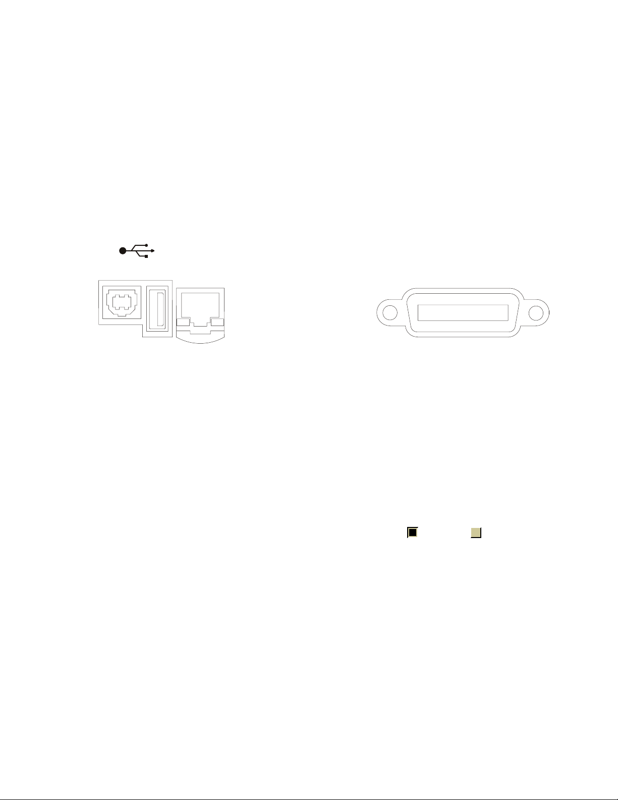
Step 2. Connect and set up the oscilloscope
The 5000 Series oscilloscope has three different interfaces you can use for
programming: USB (device), LAN, or GPIB.
All three interfaces are "live" by default, but you can turn them off if
desired. To access these settings press the Utility key on the front panel,
then press the I/O softkey, then press the Control softkey.
86%
Setting Up 2
'(9,&(
+267
121$8720',;
Figure 1 Control Connectors on Rear Panel
Using the USB (Device) Interface
1 Connect a USB cable from the controller PC's USB port to the "USB
DEVICE" port on the back of the oscilloscope.
This is a USB 2.0 high-speed port.
2 On the oscilloscope, verify that the controller interface is enabled:
a Press the Utility button.
b Using the softkeys, press I/O and Control.
c Ensure the box next to USB is selected (). If not (), use the
Entry knob to select USB; then, press the Control softkey again.
/$1
*3,%
Using the LAN Interface
1 If the controller PC isn't already connected to the local area network
(LAN), do that first.
2 Get the oscilloscope's network parameters (hostname, domain, IP
address, subnet mask, gateway IP, DNS IP, etc.) from your network
administrator.
3 Connect the oscilloscope to the local area network (LAN) by inserting
LAN cable into the "LAN" port on the back of the oscilloscope.
Agilent InfiniiVision 5000 Series Oscilloscopes Programmer's Guide 29
Page 30

2 Setting Up
4 On the oscilloscope, verify that the controller interface is enabled:
a Press the Utility button.
b Using the softkeys, press I/O and Control.
c Ensure the box next to LAN is selected ( ). If not ( ), use the
Entry knob to select LAN; then, press the Control softkey again.
5 Configure the oscilloscope's LAN interface:
a Press the Configure softkey until "LAN" is selected.
b Press the LAN Settings softkey.
c Press the Addresses softkey. Use the IP Options softkey and the
Entry knob to select DHCP, AutoIP, or netBIOS. Use the Modify
softkey (and the other softkeys and the Entry knob) to enter the IP
Address, Subnet Mask, Gateway IP, and DNS IP values. When you are
done, press the return (up arrow) softkey.
d Press the Domain softkey. Use the Modify softkey (and the other
softkeys and the Entry knob) to enter the Host name and the
Domain name. When you are done, press the return (up arrow)
softkey.
Using the GPIB Interface
1 Connect a GPIB cable from the controller PC's GPIB interface to the
"GPIB" port on the back of the oscilloscope.
2 On the oscilloscope, verify that the controller interface is enabled:
a Press the Utility button.
b Using the softkeys, press I/O and Control.
c Use the Entry knob to select "GPIB"; then, press the Control softkey
again.
Ensure the box next to GPIB is selected ( ). If not ( ), use the
Entry knob to select GPIB; then, press the Control softkey again.
3 Configure the oscilloscope's GPIB interface:
a Press the Configure softkey until "GPIB" is selected.
b Use the Entry knob to select the Address value.
30 Agilent InfiniiVision 5000 Series Oscilloscopes Programmer's Guide
Page 31

Step 3. Verify the oscilloscope connection
1 On the controller PC, click on the Agilent IO Control icon in the
taskbar and choose Agilent Connection Expert from the popup menu.
2 In the Agilent Connection Expert application, instruments connected to
the controller's USB and GPIB interfaces should automatically appear.
(You can click Refresh All to update the list of instruments on these
interfaces.)
Setting Up 2
Agilent InfiniiVision 5000 Series Oscilloscopes Programmer's Guide 31
Page 32

2 Setting Up
You must manually add instruments on LAN interfaces:
a Right-click on the LAN interface, choose Add Instrument from the
popup menu
b If the oscilloscope is on the same subnet, select it, and click OK.
32 Agilent InfiniiVision 5000 Series Oscilloscopes Programmer's Guide
Page 33

Setting Up 2
Otherwise, if the instrument is not on the same subnet, click Add
Address.
i In the next dialog, select either Hostname or IP address, and
enter the oscilloscope's hostname or IP address.
ii Click Test Connection.
Agilent InfiniiVision 5000 Series Oscilloscopes Programmer's Guide 33
Page 34

2 Setting Up
iii If the instrument is successfully opened, click OK to close the
dialog. If the instrument is not opened successfully, go back and
verify the LAN connections and the oscilloscope setup.
34 Agilent InfiniiVision 5000 Series Oscilloscopes Programmer's Guide
Page 35

Setting Up 2
3 Test some commands on the instrument:
a Right- click on the instrument and choose Send Commands To This
Instrument from the popup menu.
b In the Agilent Interactive IO application, enter commands in the
Command field and press Send Command, Read Response, or
Send&Read.
c Choose Connect>Exit from the menu to exit the Agilent Interactive
IO application.
4 In the Agilent Connection Expert application, choose File>Exit from the
menu to exit the application.
Agilent InfiniiVision 5000 Series Oscilloscopes Programmer's Guide 35
Page 36

2 Setting Up
36 Agilent InfiniiVision 5000 Series Oscilloscopes Programmer's Guide
Page 37

Agilent InfiniiVision 5000 Series Oscilloscopes
Programmer's Guide
3
Getting Started
Basic Oscilloscope Program Structure 38
Programming the Oscilloscope 40
Other Ways of Sending Commands 49
This chapter gives you an overview of programming the 5000 Series
oscilloscopes. It describes basic oscilloscope program structure and shows
how to program the oscilloscope using a few simple examples.
The getting started examples show how to send oscilloscope setup, data
capture, and query commands, and they show how to read query results.
NOTE
Language for Program Examples
The programming examples in this guide are written in Visual Basic using the Agilent VISA
COM library.
A
37
Page 38

3 Getting Started
Basic Oscilloscope Program Structure
The following figure shows the basic structure of every program you will
write for the oscilloscope.
Initializing
To ensure consistent, repeatable performance, you need to start the
program, controller, and oscilloscope in a known state. Without correct
initialization, your program may run correctly in one instance and not in
another. This might be due to changes made in configuration by previous
program runs or from the front panel of the oscilloscope.
• Program initialization defines and initializes variables, allocates
memory, or tests system configuration.
• Controller initialization ensures that the interface to the oscilloscope is
properly set up and ready for data transfer.
• Oscilloscope initialization sets the channel configuration, channel labels,
threshold voltages, trigger specification, trigger mode, timebase, and
acquisition type.
Capturing Data
Once you initialize the oscilloscope, you can begin capturing data for
analysis. Remember that while the oscilloscope is responding to commands
from the controller, it is not performing acquisitions. Also, when you
change the oscilloscope configuration, any data already captured will most
likely be rendered.
38 Agilent InfiniiVision 5000 Series Oscilloscopes Programmer's Guide
Page 39

To collect data, you use the :DIGitize command. This command clears the
waveform buffers and starts the acquisition process. Acquisition continues
until acquisition memory is full, then stops. The acquired data is displayed
by the oscilloscope, and the captured data can be measured, stored in
trace memory in the oscilloscope, or transferred to the controller for
further analysis. Any additional commands sent while :DIGitize is working
are buffered until :DIGitize is complete.
You could also put the oscilloscope into run mode, then use a wait loop in
your program to ensure that the oscilloscope has completed at least one
acquisition before you make a measurement. Agilent does not recommend
this because the needed length of the wait loop may vary, causing your
program to fail. :DIGitize, on the other hand, ensures that data capture is
complete. Also, :DIGitize, when complete, stops the acquisition process so
that all measurements are on displayed data, not on a constantly changing
data set.
Analyzing Captured Data
Getting Started 3
After the oscilloscope has completed an acquisition, you can find out more
about the data, either by using the oscilloscope measurements or by
transferring the data to the controller for manipulation by your program.
Built- in measurements include: frequency, duty cycle, period, positive
pulse width, and negative pulse width.
Using the :WAVeform commands, you can transfer the data to your
controller. You may want to display the data, compare it to a known good
measurement, or simply check logic patterns at various time intervals in
the acquisition.
Agilent InfiniiVision 5000 Series Oscilloscopes Programmer's Guide 39
Page 40

3 Getting Started
Programming the Oscilloscope
• "Referencing the IO Library" on page 40
• "Opening the Oscilloscope Connection via the IO Library" on page 41
• "Using :AUToscale to Automate Oscilloscope Setup" on page 42
• "Using Other Oscilloscope Setup Commands" on page 42
• "Capturing Data with the :DIGitize Command" on page 43
• "Reading Query Responses from the Oscilloscope" on page 45
• "Reading Query Results into String Variables" on page 46
• "Reading Query Results into Numeric Variables" on page 46
• "Reading Definite- Length Block Query Response Data" on page 46
• "Sending Multiple Queries and Reading Results" on page 47
• "Checking Instrument Status" on page 48
Referencing the IO Library
No matter which instrument programming library you use (SICL, VISA, or
VISA COM), you must reference the library from your program.
In C/C++, you must tell the compiler where to find the include and library
files (see the Agilent IO Libraries Suite documentation for more
information).
To reference the Agilent VISA COM library in Visual Basic for Applications
(VBA, which comes with Microsoft Office products like Excel):
1 Choose Tools>References... from the main menu.
2 In the References dialog, check the "VISA COM 3.0 Type Library".
40 Agilent InfiniiVision 5000 Series Oscilloscopes Programmer's Guide
Page 41

3 Click OK.
To reference the Agilent VISA COM library in Microsoft Visual Basic 6.0:
1 Choose Project>References... from the main menu.
2 In the References dialog, check the "VISA COM 3.0 Type Library".
3 Click OK.
Opening the Oscilloscope Connection via the IO Library
PC controllers communicate with the oscilloscope by sending and receiving
messages over a remote interface. Once you have opened a connection to
the oscilloscope over the remote interface, programming instructions
normally appear as ASCII character strings embedded inside write
statements of the programing language. Read statements are used to read
query responses from the oscilloscope.
For example, when using the Agilent VISA COM library in Visual Basic
(after opening the connection to the instrument using the
ResourceManager object's Open method), the FormattedIO488 object's
WriteString, WriteNumber, WriteList, or WriteIEEEBlock methods are used
for sending commands and queries. After a query is sent, the response is
read using the ReadString, ReadNumber, ReadList, or ReadIEEEBlock
methods.
Getting Started 3
The following Visual Basic statements open the connection and send a
command that turns on the oscilloscope's label display.
Dim myMgr As VisaComLib.ResourceManager
Dim myScope As VisaComLib.FormattedIO488
Set myMgr = New VisaComLib.ResourceManager
Set myScope = New VisaComLib.FormattedIO488
' Open the connection to the oscilloscope. Get the VISA Address from the
' Agilent Connection Expert (installed with Agilent IO Libraries Suite).
Set myScope.IO = myMgr.Open("<VISA Address>")
' Send a command.
myScope.WriteString ":DISPlay:LABel ON"
The ":DISPLAY:LABEL ON" in the above example is called a program
message. Program messages are explained in more detail in "Program
Message Syntax" on page 587.
Initializing the Interface and the Oscilloscope
To make sure the bus and all appropriate interfaces are in a known state,
begin every program with an initialization statement. When using the
Agilent VISA COM library, you can use the resource session object's Clear
method to clears the interface buffer:
Agilent InfiniiVision 5000 Series Oscilloscopes Programmer's Guide 41
Page 42

3 Getting Started
Dim myMgr As VisaComLib.ResourceManager
Dim myScope As VisaComLib.FormattedIO488
Set myMgr = New VisaComLib.ResourceManager
Set myScope = New VisaComLib.FormattedIO488
' Open the connection to the oscilloscope. Get the VISA Address from the
' Agilent Connection Expert (installed with Agilent IO Libraries Suite).
Set myScope.IO = myMgr.Open("<VISA Address>")
' Clear the interface buffer.
myScope.IO.Clear
When you are using GPIB, CLEAR also resets the oscilloscope's parser. The
parser is the program which reads in the instructions which you send it.
After clearing the interface, initialize the instrument to a preset state:
myScope.WriteString "*RST"
NOTE
Information for Initializing the Instrument
The actual commands and syntax for initializing the instrument are discussed in "Common
(*) Commands" on page 91.
Refer to the Agilent IO Libraries Suite documentation for information on initializing the
interface.
Using :AUToscale to Automate Oscilloscope Setup
The :AUToscale command performs a very useful function for unknown
waveforms by setting up the vertical channel, time base, and trigger level
of the instrument.
The syntax for the autoscale command is:
myScope.WriteString ":AUToscale"
Using Other Oscilloscope Setup Commands
A typical oscilloscope setup would set the vertical range and offset voltage,
the horizontal range, delay time, delay reference, trigger mode, trigger
level, and slope. An example of the commands that might be sent to the
oscilloscope are:
myScope.WriteString ":CHANnel1:PROBe 10"
myScope.WriteString ":CHANnel1:RANGe 16"
myScope.WriteString ":CHANnel1:OFFSet 1.00"
myScope.WriteString ":TIMebase:MODE NORMal"
myScope.WriteString ":TIMebase:RANGe 1E-3"
myScope.WriteString ":TIMebase:DELay 100E-6"
42 Agilent InfiniiVision 5000 Series Oscilloscopes Programmer's Guide
Page 43

Getting Started 3
Vertical is set to 16 V full- scale (2 V/div) with center of screen at 1 V and
probe attenuation set to 10. This example sets the time base at 1 ms
full- scale (100 ms/div) with a delay of 100 µs.
Example Oscilloscope Setup Code
This program demonstrates the basic command structure used to program
the oscilloscope.
' Initialize the instrument interface to a known state.
myScope.IO.Clear
' Initialize the instrument to a preset state.
myScope.WriteString "*RST"
' Set the time base mode to normal with the horizontal time at
' 50 ms/div with 0 s of delay referenced at the center of the
' graticule.
myScope.WriteString ":TIMebase:RANGe 5E-4" ' Time base to 50 us/div.
myScope.WriteString ":TIMebase:DELay 0" ' Delay to zero.
myScope.WriteString ":TIMebase:REFerence CENTer" ' Display ref. at
' center.
' Set the vertical range to 1.6 volts full scale with center screen
' at -0.4 volts with 10:1 probe attenuation and DC coupling.
myScope.WriteString ":CHANnel1:PROBe 10" ' Probe attenuation
myScope.WriteString ":CHANnel1:RANGe 1.6" ' Vertical range
myScope.WriteString ":CHANnel1:OFFSet -.4" ' Offset to -0.4.
myScope.WriteString ":CHANnel1:COUPling DC" ' Coupling to DC.
' Configure the instrument to trigger at -0.4 volts with normal
' triggering.
myScope.WriteString ":TRIGger:SWEep NORMal" ' Normal triggering.
myScope.WriteString ":TRIGger:LEVel -.4" ' Trigger level to -0.4.
myScope.WriteString ":TRIGger:SLOPe POSitive" ' Trigger on pos. slope.
' Configure the instrument for normal acquisition.
myScope.WriteString ":ACQuire:TYPE NORMal" ' Normal acquisition.
Capturing Data with the :DIGitize Command
The :DIGitize command captures data that meets the specifications set up
by the :ACQuire subsystem. When the digitize process is complete, the
acquisition is stopped. The captured data can then be measured by the
instrument or transferred to the controller for further analysis. The
captured data consists of two parts: the waveform data record, and the
preamble.
' to 10:1.
' 1.6 V full scale.
Agilent InfiniiVision 5000 Series Oscilloscopes Programmer's Guide 43
Page 44

3 Getting Started
NOTE
NOTE
Ensure New Data is Collected
When you change the oscilloscope configuration, the waveform buffers are cleared. Before
doing a measurement, send the :DIGitize command to the oscilloscope to ensure new data
has been collected.
When you send the :DIGitize command to the oscilloscope, the specified
channel signal is digitized with the current :ACQuire parameters. To obtain
waveform data, you must specify the :WAVeform parameters for the
SOURce channel, the FORMat type, and the number of POINts prior to
sending the :WAVeform:DATA? query.
Set :TIMebase:MODE to NORMal when using :DIGitize
:TIMebase:MODE must be set to NORMal to perform a :DIGitize command or to perform any
:WAVeform subsystem query. A "Settings conflict" error message will be returned if these
commands are executed when MODE is set to ROLL, XY, or DELayed. Sending the *RST
(reset) command will also set the time base mode to normal.
The number of data points comprising a waveform varies according to the
number requested in the :ACQuire subsystem. The :ACQuire subsystem
determines the number of data points, type of acquisition, and number of
averages used by the :DIGitize command. This allows you to specify exactly
what the digitized information contains.
The following program example shows a typical setup:
myScope.WriteString ":ACQuire:TYPE AVERage"
myScope.WriteString ":ACQuire:COMPlete 100"
myScope.WriteString ":ACQuire:COUNt 8"
myScope.WriteString ":DIGitize CHANnel1"
myScope.WriteString ":WAVeform:SOURce CHANnel1"
myScope.WriteString ":WAVeform:FORMat BYTE"
myScope.WriteString ":WAVeform:POINts 500"
myScope.WriteString ":WAVeform:DATA?"
This setup places the instrument into the averaged mode with eight
averages. This means that when the :DIGitize command is received, the
command will execute until the signal has been averaged at least eight
times.
After receiving the :WAVeform:DATA? query, the instrument will start
passing the waveform information.
Digitized waveforms are passed from the instrument to the controller by
sending a numerical representation of each digitized point. The format of
the numerical representation is controlled with the :WAVeform:FORMat
command and may be selected as BYTE, WORD, or ASCii.
44 Agilent InfiniiVision 5000 Series Oscilloscopes Programmer's Guide
Page 45

Getting Started 3
The easiest method of transferring a digitized waveform depends on data
structures, formatting available and I/O capabilities. You must scale the
integers to determine the voltage value of each point. These integers are
passed starting with the left most point on the instrument's display.
For more information, see the waveform subsystem commands and
corresponding program code examples in ":WAVeform Commands" on
page 442.
NOTE
Aborting a Digitize Operation Over the Programming Interface
When using the programming interface, you can abort a digitize operation by sending a
Device Clear over the bus (for example, myScope.IO.Clear).
Reading Query Responses from the Oscilloscope
After receiving a query (command header followed by a question mark),
the instrument interrogates the requested function and places the answer
in its output queue. The answer remains in the output queue until it is
read or another command is issued. When read, the answer is transmitted
across the interface to the designated listener (typically a controller).
The statement for reading a query response message from an instrument's
output queue typically has a format specification for handling the response
message.
When using the VISA COM library in Visual Basic, you use different read
methods (ReadString, ReadNumber, ReadList, or ReadIEEEBlock) for the
various query response formats. For example, to read the result of the
query command :CHANnel1:COUPling? you would execute the statements:
myScope.WriteString ":CHANnel1:COUPling?"
Dim strQueryResult As String
strQueryResult = myScope.ReadString
This reads the current setting for the channel one coupling into the string
variable strQueryResult.
All results for queries (sent in one program message) must be read before
another program message is sent.
Sending another command before reading the result of the query clears
the output buffer and the current response. This also causes an error to
be placed in the error queue.
Executing a read statement before sending a query causes the controller to
wait indefinitely.
The format specification for handling response messages depends on the
programming language.
Agilent InfiniiVision 5000 Series Oscilloscopes Programmer's Guide 45
Page 46

3 Getting Started
Reading Query Results into String Variables
The output of the instrument may be numeric or character data depending
on what is queried. Refer to the specific command descriptions in
"Commands by Subsystem" on page 89 for the formats and types of data
returned from queries.
NOTE
Express String Variables Using Exact Syntax
In Visual Basic, string variables are case sensitive and must be expressed exactly the same
each time they are used.
The following example shows numeric data being returned to a string
variable:
myScope.WriteString ":CHANnel1:RANGe?"
Dim strQueryResult As String
strQueryResult = myScope.ReadString
MsgBox "Range (string):" + strQueryResult
After running this program, the controller displays:
Range (string): +40.0E+00
Reading Query Results into Numeric Variables
The following example shows numeric data being returned to a numeric
variable:
myScope.WriteString ":CHANnel1:RANGe?"
Dim varQueryResult As Variant
strQueryResult = myScope.ReadNumber
MsgBox "Range (variant):" + CStr(varQueryResult)
After running this program, the controller displays:
Range (variant): 40
Reading Definite-Length Block Query Response Data
Definite- length block query response data allows any type of
device-dependent data to be transmitted over the system interface as a
series of 8- bit binary data bytes. This is particularly useful for sending
large quantities of data or 8- bit extended ASCII codes. The syntax is a
pound sign (#) followed by a non-zero digit representing the number of
digits in the decimal integer. After the non-zero digit is the decimal
integer that states the number of 8-bit data bytes being sent. This is
followed by the actual data.
For example, for transmitting 1000 bytes of data, the syntax would be:
46 Agilent InfiniiVision 5000 Series Oscilloscopes Programmer's Guide
Page 47

Getting Started 3
S
E
/TLADQN
AXSDRNEC@S@SDQLHM@SNQ
/TLADQNE#XSDR
NAD5Q@MRLHSSDC
%HFHSR
5G@S'NKKNV
"BST@K%@S@
Figure 2 Definite-length block response data
The "8" states the number of digits that follow, and "00001000" states the
number of bytes to be transmitted.
The VISA COM library's ReadIEEEBlock and WriteIEEEBlock methods
understand the definite- length block syntax, so you can simply use
variables that contain the data:
' Read oscilloscope setup using ":SYSTem:SETup?" query.
myScope.WriteString ":SYSTem:SETup?"
Dim varQueryResult As Variant
varQueryResult = myScope.ReadIEEEBlock(BinaryType_UI1)
' Write learn string back to oscilloscope using ":SYSTem:SETup" command:
myScope.WriteIEEEBlock ":SYSTem:SETup ", varQueryResult
Sending Multiple Queries and Reading Results
You can send multiple queries to the instrument within a single command
string, but you must also read them back as a single query result. This can
be accomplished by reading them back into a single string variable,
multiple string variables, or multiple numeric variables.
For example, to read the :TIMebase:RANGe?;DELay? query result into a
single string variable, you could use the commands:
myScope.WriteString ":TIMebase:RANGe?;DELay?"
Dim strQueryResult As String
strQueryResult = myScope.ReadString
MsgBox "Timebase range; delay:" + strQueryResult
When you read the result of multiple queries into a single string variable,
each response is separated by a semicolon. For example, the output of the
previous example would be:
Timebase range; delay: <range_value>;<delay_value>
To read the :TIMebase:RANGe?;DELay? query result into multiple string
variables, you could use the ReadList method to read the query results
into a string array variable using the commands:
myScope.WriteString ":TIMebase:RANGe?;DELay?"
Dim strResults() As String
Agilent InfiniiVision 5000 Series Oscilloscopes Programmer's Guide 47
Page 48

3 Getting Started
Checking Instrument Status
strResults() = myScope.ReadList(ASCIIType_BSTR)
MsgBox "Timebase range: " + strResults(0) + ", delay: " + strResults(1)
To read the :TIMebase:RANGe?;DELay? query result into multiple numeric
variables, you could use the ReadList method to read the query results
into a variant array variable using the commands:
myScope.WriteString ":TIMebase:RANGe?;DELay?"
Dim varResults() As Variant
varResults() = myScope.ReadList
MsgBox "Timebase range: " + FormatNumber(varResults(0) * 1000, 4) + _
" ms, delay: " + FormatNumber(varResults(1) * 1000000, 4) + " us"
Status registers track the current status of the instrument. By checking
the instrument status, you can find out whether an operation has been
completed, whether the instrument is receiving triggers, and more.
For more information, see "Status Reporting" on page 553 which explains
how to check the status of the instrument.
48 Agilent InfiniiVision 5000 Series Oscilloscopes Programmer's Guide
Page 49

Other Ways of Sending Commands
Standard Commands for Programmable Instrumentation (SCPI) can be sent
via a Telnet socket or through the Browser Web Control.
Telnet Sockets
The following information is provided for programmers who wish to
control the oscilloscope with SCPI commands in a Telnet session.
To connect to the oscilloscope via a telnet socket, issue the following
command:
telnet <hostname> 5024
where <hostname> is the hostname of the oscilloscope. This will give you a
command line with prompt.
For a command line without a prompt, use port 5025. For example:
Getting Started 3
telnet <hostname> 5025
Sending SCPI Commands Using Browser Web Control
To send SCPI commands using the Browser Web Control feature, establish
a connection to the oscilloscope via LAN as described in the 5000 Series
Oscilloscopes User's Guide. When you make the connection to the
oscilloscope via LAN and the instrument's welcome page is displayed,
select the Browser Web Control tab, then select the Remote
Programming link.
Agilent InfiniiVision 5000 Series Oscilloscopes Programmer's Guide 49
Page 50

3 Getting Started
50 Agilent InfiniiVision 5000 Series Oscilloscopes Programmer's Guide
Page 51

Agilent InfiniiVision 5000 Series Oscilloscopes
Programmer's Guide
4
Commands Quick Reference
Command Summary 52
Syntax Elements 85
A
51
Page 52

4 Commands Quick Reference
Command Summary
Table 2 Common (*) Commands Summary
Command Query Options and Query Returns
*CLS (see page 95) n/a n/a
*ESE <mask> (see
page 96)
n/a *ESR? (see page 98) <status> ::= 0 to 255; an integer
n/a *IDN? (see page 98) AGILENT TECHNOLOGIES,<model>,
n/a *LRN? (see page 101) <learn_string> ::= current
*ESE? (see page 97) <mask> ::= 0 to 255; an integer
in NR1 format:
Bit Weight Name Enables
--- ------ ---- ---------7 128 PON Power On
6 64 URQ User Request
5 32 CME Command Error
4 16 EXE Execution Error
3 8 DDE Dev. Dependent Error
2 4 QYE Query Error
1 2 RQL Request Control
0 1 OPC Operation Complete
in NR1 format
<serial number>,X.XX.XX
<model> ::= the model number of
the instrument
<serial number> ::= the serial
number of the instrument
<X.XX.XX> ::= the software
revision of the instrument
instrument setup as a block of
data in IEEE 488.2 # format
*OPC (see page 102) *OPC? (see page 102) ASCII "1" is placed in the output
queue when all pending device
operations have completed.
52 Agilent InfiniiVision 5000 Series Oscilloscopes Programmer's Guide
Page 53

Commands Quick Reference 4
Table 2 Common (*) Commands Summary (continued)
Command Query Options and Query Returns
n/a *OPT? (see page 103) <return_value> ::= 0,0,<license
info>
<license info> ::= <All field>,
<reserved>, <reserved>,
<reserved>, <reserved>,
<reserved>, <Low Speed Serial>,
<Automotive Serial>, <reserved>,
<Secure>, <reserved>,
<reserved>, <reserved>,
<reserved>,
<RS-232/UART Serial>, <reserved>
<All field> ::= {0 | All}
<reserved> ::= 0
<Low Speed Serial> ::= {0 | LSS}
<Automotive Serial> ::= {0 | AMS}
<Secure> ::= {0 | SEC}
<RS-232/UART Serial> ::= {0 |
232}
*RCL <value> (see
page 104)
*RST (see page 105) n/a See *RST (Reset) (see page 105)
*SAV <value> (see
page 108)
*SRE <mask> (see
page 109)
n/a <value> ::= {0 | 1 | 2 | 3 | 4 |
5 | 6 | 7 | 8 | 9}
n/a <value> ::= {0 | 1 | 2 | 3 | 4 |
5 | 6 | 7 | 8 | 9}
*SRE? (see page 110) <mask> ::= sum of all bits that
are set, 0 to 255; an integer in
NR1 format. <mask> ::= following
values:
Bit Weight Name Enables
--- ------ ---- ---------7 128 OPER Operation Status Reg
6 64 ---- (Not used.)
5 32 ESB Event Status Bit
4 16 MAV Message Available
3 8 ---- (Not used.)
2 4 MSG Message
1 2 USR User
0 1 TRG Trigger
Agilent InfiniiVision 5000 Series Oscilloscopes Programmer's Guide 53
Page 54

4 Commands Quick Reference
Table 2 Common (*) Commands Summary (continued)
Command Query Options and Query Returns
n/a *STB? (see page 111) <value> ::= 0 to 255; an integer
in NR1 format, as shown in the
following:
Bit Weight Name "1" Indicates
--- ------ ---- --------------7 128 OPER Operation status
condition occurred.
6 64 RQS/ Instrument is
MSS requesting service.
5 32 ESB Enabled event status
condition occurred.
4 16 MAV Message available.
3 8 ---- (Not used.)
2 4 MSG Message displayed.
1 2 USR User event
condition occurred.
0 1 TRG A trigger occurred.
*TRG (see page 113) n/a n/a
n/a *TST? (see page 114) <result> ::= 0 or non-zero value;
an integer in NR1 format
*WAI (see page 115) n/a n/a
Table 3 Root (:) Commands Summary
Command Query Options and Query Returns
n/a :AER? (see page 119) {0 | 1}; an integer in NR1 format
:AUToscale
[<source>[,..,<source
>]] (see page 120)
:AUToscale:AMODE
<value> (see
page 122)
:AUToscale:CHANnels
<value> (see
page 123)
n/a <source> ::= CHANnel<n>
<source> can be repeated up to 5
times
<n> ::= 1-2 or 1-4 in NR1 format
:AUToscale:AMODE?
(see page 122)
:AUToscale:CHANnels?
(see page 123)
<value> ::= {NORMal | CURRent}}
<value> ::= {ALL | DISPlayed}}
:BLANk [<source>]
(see page 124)
:CDISplay (see
page 125)
54 Agilent InfiniiVision 5000 Series Oscilloscopes Programmer's Guide
n/a <source> ::= {CHANnel<n>} |
FUNCtion | MATH}
<n> ::= 1-2 or 1-4 in NR1 format
n/a n/a
Page 55

Commands Quick Reference 4
Table 3 Root (:) Commands Summary (continued)
Command Query Options and Query Returns
:DIGitize
[<source>[,..,<source
>]] (see page 126)
:HWEenable <n> (see
page 128)
n/a :HWERregister:CONDiti
n/a :HWERegister[:EVENt]?
:MERGe <pixel memory>
(see page 134)
:OPEE <n> (see
page 135)
n/a :OPERregister:CONDiti
n/a :OPERegister[:EVENt]?
:OVLenable <mask>
(see page 141)
n/a <source> ::= {CHANnel<n> |
:HWEenable? (see
page 128)
on? (see page 130)
(see page 132)
n/a <pixel memory> ::= {PMEMory{0 | 1
:OPEE? (see page 136) <n> ::= 16-bit integer in NR1
on? (see page 137)
(see page 139)
:OVLenable? (see
page 142)
FUNCtion | MATH}
<source> can be repeated up to 5
times
<n> ::= 1-2 or 1-4 in NR1 format
<n> ::= 16-bit integer in NR1
format
<n> ::= 16-bit integer in NR1
format
<n> ::= 16-bit integer in NR1
format
| 2 | 3 | 4 | 5 | 6 | 7 | 8 | 9}}
format
<n> ::= 16-bit integer in NR1
format
<n> ::= 16-bit integer in NR1
format
<mask> ::= 16-bit integer in NR1
format as shown:
n/a :OVLRegister? (see
page 143)
:PRINt [<options>]
(see page 145)
n/a <options> ::= [<print
Bit Weight Input
--- ------ ---------10 1024 Ext Trigger Fault
9 512 Channel 4 Fault
8 256 Channel 3 Fault
7 128 Channel 2 Fault
6 64 Channel 1 Fault
4 16 Ext Trigger OVL
3 8 Channel 4 OVL
2 4 Channel 3 OVL
1 2 Channel 2 OVL
0 1 Channel 1 OVL
<value> ::= integer in NR1
format. See OVLenable for <value>
option>][,..,<print option>]
<print option> ::= {COLor |
GRAYscale | PRINter0 | BMP8bit |
BMP | PNG | NOFactors | FACTors}
<print option> can be repeated up
to 5 times.
Agilent InfiniiVision 5000 Series Oscilloscopes Programmer's Guide 55
Page 56

4 Commands Quick Reference
Table 3 Root (:) Commands Summary (continued)
Command Query Options and Query Returns
:RUN (see page 146) n/a n/a
n/a :SERial (see
page 147)
:SINGle (see
page 148)
n/a :STATus? <display>
:STOP (see page 150) n/a n/a
n/a :TER? (see page 151) {0 | 1}
:VIEW <source> (see
page 152)
n/a n/a
(see page 149)
n/a <source> ::= {CHANnel<n> |
<return value> ::= unquoted
string containing serial number
{0 | 1}
<display> ::= {CHANnel<n> |
FUNCtion | MATH}
<n> ::= 1-2 or 1-4 in NR1 format
PMEMory{0 | 1 | 2 | 3 | 4 | 5 | 6
| 7 | 8 | 9} | FUNCtion | MATH}
<n> ::= 1-2 or 1-4 in NR1 format
Table 4 :ACQuire Commands Summary
Command Query Options and Query Returns
n/a :ACQuire:AALias? (see
page 155)
{1 | 0}
:ACQuire:COMPlete
<complete> (see
page 156)
:ACQuire:COUNt
<count> (see
page 157)
:ACQuire:DAALias
<mode> (see page 158)
:ACQuire:MODE <mode>
(see page 159)
n/a :ACQuire:POINts? (see
:ACQuire:SEGMented:CO
UNt <count> (see
page 161)
:ACQuire:SEGMented:IN
Dex <index> (see
page 162)
56 Agilent InfiniiVision 5000 Series Oscilloscopes Programmer's Guide
:ACQuire:COMPlete?
(see page 156)
:ACQuire:COUNt? (see
page 157)
:ACQuire:DAALias?
(see page 158)
:ACQuire:MODE? (see
page 159)
page 160)
:ACQuire:SEGMented:CO
UNt? (see page 161)
:ACQuire:SEGMented:IN
Dex? (see page 162)
<complete> ::= 100; an integer in
NR1 format
<count> ::= an integer from 2 to
65536 in NR1 format
<mode> ::= {DISable | AUTO}
<mode> ::= {RTIMe | ETIMe |
SEGMented}
<# points> ::= an integer in NR1
format
<count> ::= an integer from 2 to
250 in NR1 format (with Option
SGM)
<index> ::= an integer from 2 to
250 in NR1 format (with Option
SGM)
Page 57

Commands Quick Reference 4
Table 4 :ACQuire Commands Summary (continued)
Command Query Options and Query Returns
n/a :ACQuire:SRATe? (see
page 164)
:ACQuire:TYPE <type>
(see page 165)
:ACQuire:TYPE? (see
page 165)
<sample_rate> ::= sample rate
(samples/s) in NR3 format
<type> ::= {NORMal | AVERage |
HRESolution | PEAK}
Table 5 :CALibrate Commands Summary
Command Query Options and Query Returns
n/a :CALibrate:DATE? (see
page 168)
:CALibrate:LABel
<string> (see
page 169)
:CALibrate:STARt (see
page 170)
n/a :CALibrate:STATus?
:CALibrate:LABel?
(see page 169)
n/a n/a
(see page 171)
<return value> ::=
<day>,<month>,<year>; all in NR1
format
<string> ::= quoted ASCII string
up to 32 characters
<return value> ::=
ALL,<status_code>,<status_string
>
<status_code> ::= an integer
status code
<status_string> ::= an ASCII
status string
n/a :CALibrate:SWITch?
(see page 172)
n/a :CALibrate:TEMPeratur
e? (see page 173)
n/a :CALibrate:TIME? (see
page 174)
Agilent InfiniiVision 5000 Series Oscilloscopes Programmer's Guide 57
{PROTected | UNPRotected}
<return value> ::= degrees C
delta since last cal in NR3
format
<return value> ::=
<hours>,<minutes>,<seconds>; all
in NR1 format
Page 58

4 Commands Quick Reference
Table 6 :CHANnel<n> Commands Summary
Command Query Options and Query Returns
:CHANnel<n>:BWLimit
{{0 | OFF} | {1 |
ON}} (see page 178)
:CHANnel<n>:COUPling
<coupling> (see
page 179)
:CHANnel<n>:DISPlay
{{0 | OFF} | {1 |
ON}} (see page 180)
:CHANnel<n>:IMPedance
<impedance> (see
page 181)
:CHANnel<n>:INVert
{{0 | OFF} | {1 |
ON}} (see page 182)
:CHANnel<n>:LABel
<string> (see
page 183)
:CHANnel<n>:OFFSet
<offset>[suffix] (see
page 184)
:CHANnel<n>:BWLimit?
(see page 178)
:CHANnel<n>:COUPling?
(see page 179)
:CHANnel<n>:DISPlay?
(see page 180)
:CHANnel<n>:IMPedance
? (see page 181)
:CHANnel<n>:INVert?
(see page 182)
:CHANnel<n>:LABel?
(see page 183)
:CHANnel<n>:OFFSet?
(see page 184)
{0 | 1}
<n> ::= 1-2 or 1-4 in NR1 format
<coupling> ::= {AC | DC}
<n> ::= 1-2 or 1-4 in NR1 format
{0 | 1}
<n> ::= 1-2 or 1-4 in NR1 format
<impedance> ::= {ONEMeg | FIFTy}
<n> ::= 1-2 or 1-4 in NR1 format
{0 | 1}
<n> ::= 1-2 or 1-4 in NR1 format
<string> ::= any series of 6 or
less ASCII characters enclosed in
quotation marks
<n> ::= 1-2 or 1-4 in NR1 format
<offset> ::= Vertical offset
value in NR3 format
[suffix] ::= {V | mV}
<n> ::= 1-2 or 1-4; in NR1 format
:CHANnel<n>:PROBe
<attenuation> (see
page 185)
n/a :CHANnel<n>:PROBe:ID?
:CHANnel<n>:PROBe:SKE
W <skew_value> (see
page 187)
:CHANnel<n>:PROBe:STY
Pe <signal type> (see
page 188)
:CHANnel<n>:PROTectio
n (see page 189)
58 Agilent InfiniiVision 5000 Series Oscilloscopes Programmer's Guide
:CHANnel<n>:PROBe?
(see page 185)
(see page 186)
:CHANnel<n>:PROBe:SKE
W? (see page 187)
:CHANnel<n>:PROBe:STY
Pe? (see page 188)
:CHANnel<n>:PROTectio
n? (see page 189)
<attenuation> ::= Probe
attenuation ratio in NR3 format
<n> ::= 1-2 or 1-4r in NR1 format
<probe id> ::= unquoted ASCII
string up to 11 characters
<n> ::= 1-2 or 1-4 in NR1 format
<skew_value> ::= -100 ns to +100
ns in NR3 format
<n> ::= 1-2 or 1-4 in NR1 format
<signal type> ::= {DIFFerential |
SINGle}
<n> ::= 1-2 or 1-4 in NR1 format
{NORM | TRIP}
<n> ::= 1-2 or 1-4 in NR1 format
Page 59

Commands Quick Reference 4
Table 6 :CHANnel<n> Commands Summary (continued)
Command Query Options and Query Returns
:CHANnel<n>:RANGe
<range>[suffix] (see
page 190)
:CHANnel<n>:SCALe
<scale>[suffix] (see
page 191)
:CHANnel<n>:UNITs
<units> (see
page 192)
:CHANnel<n>:VERNier
{{0 | OFF} | {1 |
ON}} (see page 193)
:CHANnel<n>:RANGe?
(see page 190)
:CHANnel<n>:SCALe?
(see page 191)
:CHANnel<n>:UNITs?
(see page 192)
:CHANnel<n>:VERNier?
(see page 193)
<range> ::= Vertical full-scale
range value in NR3 format
[suffix] ::= {V | mV}
<n> ::= 1-2 or 1-4 in NR1 format
<scale> ::= Vertical units per
division value in NR3 format
[suffix] ::= {V | mV}
<n> ::= 1-2 or 1-4 in NR1 format
<units> ::= {VOLT | AMPere}
<n> ::= 1-2 or 1-4 in NR1 format
{0 | 1}
<n> ::= 1-2 or 1-4 in NR1 format
Table 7 :DISPlay Commands Summary
Command Query Options and Query Returns
:DISPlay:CLEar (see
page 196)
n/a n/a
:DISPlay:DATA
[<format>][,][<area>]
[,][<palette>]<displa
y data> (see
page 197)
:DISPlay:LABel {{0 |
OFF} | {1 | ON}} (see
page 199)
:DISPlay:LABList
<binary block> (see
page 200)
:DISPlay:DATA?
[<format>][,][<area>]
[,][<palette>] (see
page 197)
:DISPlay:LABel? (see
page 199)
:DISPlay:LABList?
(see page 200)
<format> ::= {TIFF} (command)
<area> ::= {GRATicule} (command)
<palette> ::= {MONochrome}
(command)
<format> ::= {TIFF | BMP |
BMP8bit | PNG} (query)
<area> ::= {GRATicule | SCReen}
(query)
<palette> ::= {MONochrome |
GRAYscale | COLor} (query)
<display data> ::= data in IEEE
488.2 # format
{0 | 1}
<binary block> ::= an ordered
list of up to 75 labels, each 6
characters maximum, separated by
newline characters
Agilent InfiniiVision 5000 Series Oscilloscopes Programmer's Guide 59
Page 60

4 Commands Quick Reference
Table 7 :DISPlay Commands Summary (continued)
Command Query Options and Query Returns
:DISPlay:PERSistence
<value> (see
page 201)
:DISPlay:SOURce
<value> (see
page 202)
:DISPlay:VECTors {{1
| ON} | {0 | OFF}}
(see page 203)
:DISPlay:PERSistence?
(see page 201)
:DISPlay:SOURce? (see
page 202)
:DISPlay:VECTors?
(see page 203)
<value> ::= {MINimum | INFinite}}
<value> ::= {PMEMory{0 | 1 | 2 |
3 | 4 | 5 | 6 | 7 | 8 | 9}}
{1 | 0}
Table 8 :EXTernal Trigger Commands Summary
Command Query Options and Query Returns
:EXTernal:BWLimit
<bwlimit> (see
page 206)
:EXTernal:IMPedance
<value> (see
page 207)
:EXTernal:PROBe
<attenuation> (see
page 208)
:EXTernal:BWLimit?
(see page 206)
:EXTernal:IMPedance?
(see page 207)
:EXTernal:PROBe? (see
page 208)
<bwlimit> ::= {0 | OFF}
<impedance> ::= {ONEMeg | FIFTy}
<attenuation> ::= probe
attenuation ratio in NR3 format
n/a :EXTernal:PROBe:ID?
(see page 209)
:EXTernal:PROBe:STYPe
<signal type> (see
page 210)
:EXTernal:PROTection[
:CLEar] (see
page 211)
:EXTernal:RANGe
<range>[<suffix>]
(see page 212)
:EXTernal:UNITs
<units> (see
page 213)
60 Agilent InfiniiVision 5000 Series Oscilloscopes Programmer's Guide
:EXTernal:PROBe:STYPe
? (see page 210)
:EXTernal:PROTection?
(see page 211)
:EXTernal:RANGe? (see
page 212)
:EXTernal:UNITs? (see
page 213)
<probe id> ::= unquoted ASCII
string up to 11 characters
<signal type> ::= {DIFFerential |
SINGle}
{NORM | TRIP}
<range> ::= vertical full-scale
range value in NR3 format
<suffix> ::= {V | mV}
<units> ::= {VOLT | AMPere}
Page 61

Commands Quick Reference 4
Table 9 :FUNCtion Commands Summary
Command Query Options and Query Returns
:FUNCtion:CENTer
<frequency> (see
page 217)
:FUNCtion:DISPlay {{0
| OFF} | {1 | ON}}
(see page 218)
:FUNCtion:GOFT:OPERat
ion <operation> (see
page 219)
:FUNCtion:GOFT:SOURce
1 <source> (see
page 220)
:FUNCtion:GOFT:SOURce
2 <source> (see
page 221)
:FUNCtion:OFFSet
<offset> (see
page 222)
:FUNCtion:CENTer?
(see page 217)
:FUNCtion:DISPlay?
(see page 218)
:FUNCtion:GOFT:OPERat
ion? (see page 219)
:FUNCtion:GOFT:SOURce
1? (see page 220)
:FUNCtion:GOFT:SOURce
2? (see page 221)
:FUNCtion:OFFSet?
(see page 222)
<frequency> ::= the current
center frequency in NR3 format.
The range of legal values is from
0 Hz to 25 GHz.
{0 | 1}
<operation> ::= {ADD | SUBTract |
MULTiply}
<source> ::= CHANnel<n>
<n> ::= {1 | 2 | 3 | 4} for 4ch
models
<n> ::= {1 | 2} for 2ch models
<source> ::= CHANnel<n>
<n> ::= {{1 | 2} | {3 | 4}} for
4ch models, depending on SOURce1
selection
<n> ::= {1 | 2} for 2ch models
<offset> ::= the value at center
screen in NR3 format.
The range of legal values is
+/-10 times the current
sensitivity of the selected
function.
:FUNCtion:OPERation
<operation> (see
page 223)
:FUNCtion:RANGe
<range> (see
page 224)
Agilent InfiniiVision 5000 Series Oscilloscopes Programmer's Guide 61
:FUNCtion:OPERation?
(see page 223)
:FUNCtion:RANGe? (see
page 224)
<operation> ::= {ADD | SUBTract |
MULTiply | INTegrate |
DIFFerentiate | FFT | SQRT}
<range> ::= the full-scale
vertical axis value in NR3
format.
The range for ADD, SUBT, MULT is
8E-6 to 800E+3. The range for the
INTegrate function is 8E-9 to
400E+3.
The range for the DIFFerentiate
function is 80E-3 to 8.0E12
(depends on current sweep speed).
The range for the FFT function is
8 to 800 dBV.
Page 62

4 Commands Quick Reference
Table 9 :FUNCtion Commands Summary (continued)
Command Query Options and Query Returns
:FUNCtion:REFerence
<level> (see
page 225)
:FUNCtion:SCALe
<scale
value>[<suffix>] (see
page 226)
:FUNCtion:SOURce1
<source> (see
page 227)
:FUNCtion:SOURce2
<source> (see
page 228)
:FUNCtion:REFerence?
(see page 225)
:FUNCtion:SCALe? (see
page 226)
:FUNCtion:SOURce1?
(see page 227)
:FUNCtion:SOURce2?
(see page 228)
<level> ::= the current reference
level in NR3 format.
The range of legal values is from
400.0 dBV to +400.0 dBV
(depending on current range
value).
<scale value> ::= integer in NR1
format
<suffix> ::= {V | dB}
<source> ::= {CHANnel<n> | GOFT}
<n> ::= {1 | 2 | 3 | 4} for 4ch
models
<n> ::= {1 | 2} for 2ch models
GOFT is only for FFT, INTegrate,
DIFFerentiate, and SQRT
operations.
<source> ::= {CHANnel<n> | NONE}
<n> ::= {{1 | 2} | {3 | 4}} for
4ch models, depending on SOURce1
selection
<n> ::= {1 | 2} for 2ch models
:FUNCtion:SPAN <span>
(see page 229)
:FUNCtion:WINDow
<window> (see
page 230)
:FUNCtion:SPAN? (see
page 229)
:FUNCtion:WINDow?
(see page 230)
<span> ::= the current frequency
span in NR3 format.
Legal values are 1 Hz to 100 GHz.
<window> ::= {RECTangular |
HANNing | FLATtop | BHARris}
Table 1 0 :HARDcopy Commands Summary
Command Query Options and Query Returns
:HARDcopy:AREA <area>
(see page 233)
:HARDcopy:APRinter
<active_printer> (see
page 234)
:HARDcopy:AREA? (see
page 233)
:HARDcopy:APRinter?
(see page 234)
<area> ::= SCReen
<active_printer> ::= {<index> |
<name>}
<index> ::= integer index of
printer in list
<name> ::= name of printer in
list
62 Agilent InfiniiVision 5000 Series Oscilloscopes Programmer's Guide
Page 63

Commands Quick Reference 4
Table 1 0 :HARDcopy Commands Summary (continued)
Command Query Options and Query Returns
:HARDcopy:FACTors {{0
| OFF} | {1 | ON}}
(see page 235)
:HARDcopy:FFEed {{0 |
OFF} | {1 | ON}} (see
page 236)
:HARDcopy:INKSaver
{{0 | OFF} | {1 |
ON}} (see page 237)
:HARDcopy:PALette
<palette> (see
page 238)
n/a :HARDcopy:PRinter:LIS
:HARDcopy:STARt (see
page 240)
:HARDcopy:FACTors?
(see page 235)
:HARDcopy:FFEed? (see
page 236)
:HARDcopy:INKSaver?
(see page 237)
:HARDcopy:PALette?
(see page 238)
T? (see page 239)
n/a n/a
{0 | 1}
{0 | 1}
{0 | 1}
<palette> ::= {COLor | GRAYscale
| NONE}
<list> ::= [<printer_spec>] ...
[printer_spec>]
<printer_spec> ::=
"<index>,<active>,<name>;"
<index> ::= integer index of
printer
<active> ::= {Y | N}
<name> ::= name of printer
Table 1 1 :MARKer Commands Summary
Command Query Options and Query Returns
:MARKer:MODE <mode>
(see page 243)
:MARKer:X1Position
<position>[suffix]
(see page 244)
:MARKer:X1Y1source
<source> (see
page 245)
Agilent InfiniiVision 5000 Series Oscilloscopes Programmer's Guide 63
:MARKer:MODE? (see
page 243)
:MARKer:X1Position?
(see page 244)
:MARKer:X1Y1source?
(see page 245)
<mode> ::= {OFF | MEASurement |
MANual}
<position> ::= X1 cursor position
value in NR3 format
[suffix] ::= {s | ms | us | ns |
ps | Hz | kHz | MHz}
<return_value> ::= X1 cursor
position value in NR3 format
<source> ::= {CHANnel<n> |
FUNCtion | MATH}
<n> ::= 1-2 or 1-4 in NR1 format
<return_value> ::= <source>
Page 64

4 Commands Quick Reference
Table 1 1 :MARKer Commands Summary (continued)
Command Query Options and Query Returns
:MARKer:X2Position
<position>[suffix]
(see page 246)
:MARKer:X2Y2source
<source> (see
page 247)
n/a :MARKer:XDELta? (see
:MARKer:Y1Position
<position>[suffix]
(see page 249)
:MARKer:Y2Position
<position>[suffix]
(see page 250)
:MARKer:X2Position?
(see page 246)
:MARKer:X2Y2source?
(see page 247)
page 248)
:MARKer:Y1Position?
(see page 249)
:MARKer:Y2Position?
(see page 250)
<position> ::= X2 cursor position
value in NR3 format
[suffix] ::= {s | ms | us | ns |
ps | Hz | kHz | MHz}
<return_value> ::= X2 cursor
position value in NR3 format
<source> ::= {CHANnel<n> |
FUNCtion | MATH}
<n> ::= 1-2 or 1-4 in NR1 format
<return_value> ::= <source>
<return_value> ::= X cursors
delta value in NR3 format
<position> ::= Y1 cursor position
value in NR3 format
[suffix] ::= {V | mV | dB}
<return_value> ::= Y1 cursor
position value in NR3 format
<position> ::= Y2 cursor position
value in NR3 format
[suffix] ::= {V | mV | dB}
<return_value> ::= Y2 cursor
position value in NR3 format
n/a :MARKer:YDELta? (see
page 251)
<return_value> ::= Y cursors
delta value in NR3 format
Table 1 2 :MEASure Commands Summary
Command Query Options and Query Returns
:MEASure:CLEar (see
page 259)
:MEASure:COUNter
[<source>] (see
page 260)
n/a n/a
:MEASure:COUNter?
[<source>] (see
page 260)
<source> ::= {CHANnel<n> |
EXTernal}
<n> ::= 1-2 or 1-4 in NR1 format
<return_value> ::= counter
frequency in Hertz in NR3 format
64 Agilent InfiniiVision 5000 Series Oscilloscopes Programmer's Guide
Page 65

Commands Quick Reference 4
Table 1 2 :MEASure Commands Summary (continued)
Command Query Options and Query Returns
:MEASure:DEFine
DELay, <delay spec>
(see page 261)
:MEASure:DEFine
THResholds,
<threshold spec> (see
page 261)
:MEASure:DELay
[<source1>]
[,<source2>] (see
page 264)
:MEASure:DUTYcycle
[<source>] (see
page 266)
:MEASure:DEFine?
DELay (see page 262)
:MEASure:DEFine?
THResholds (see
page 262)
:MEASure:DELay?
[<source1>]
[,<source2>] (see
page 264)
:MEASure:DUTYcycle?
[<source>] (see
page 266)
<delay spec> ::=
<edge_spec1>,<edge_spec2>
edge_spec1 ::=
[<slope>]<occurrence>
edge_spec2 ::=
[<slope>]<occurrence>
<slope> ::= {+ | -}
<occurrence> ::= integer
<threshold spec> ::= {STANdard} |
{<threshold mode>,<upper>,
<middle>,<lower>}
<threshold mode> ::= {PERCent |
ABSolute}
<source1,2> ::= {CHANnel<n> |
FUNCtion | MATH}
<n> ::= 1-2 or 1-4 in NR1 format
<return_value> ::=
floating-point number delay time
in seconds in NR3 format
<source> ::= {CHANnel<n> |
FUNCtion | MATH}
<n> ::= 1-2 or 1-4 in NR1 format
<return_value> ::= ratio of
positive pulse width to period in
NR3 format
:MEASure:FALLtime
[<source>] (see
page 267)
:MEASure:FREQuency
[<source>] (see
page 268)
:MEASure:NWIDth
[<source>] (see
page 269)
Agilent InfiniiVision 5000 Series Oscilloscopes Programmer's Guide 65
:MEASure:FALLtime?
[<source>] (see
page 267)
:MEASure:FREQuency?
[<source>] (see
page 268)
:MEASure:NWIDth?
[<source>] (see
page 269)
<source> ::= {CHANnel<n> |
FUNCtion | MATH}
<n> ::= 1-2 or 1-4 in NR1 format
<return_value> ::= time in
seconds between the lower and
upper thresholds in NR3 format
<source> ::= {CHANnel<n> |
FUNCtion | MATH}
<n> ::= 1-2 or 1-4 in NR1 format
<return_value> ::= frequency in
Hertz in NR3 format
<source> ::= {CHANnel<n> |
FUNCtion | MATH}
<n> ::= 1-2 or 1-4 in NR1 format
<return_value> ::= negative
pulse width in seconds-NR3 format
Page 66

4 Commands Quick Reference
Table 1 2 :MEASure Commands Summary (continued)
Command Query Options and Query Returns
:MEASure:OVERshoot
[<source>] (see
page 270)
:MEASure:PERiod
[<source>] (see
page 272)
:MEASure:PHASe
[<source1>]
[,<source2>] (see
page 273)
:MEASure:PREShoot
[<source>] (see
page 274)
:MEASure:OVERshoot?
[<source>] (see
page 270)
:MEASure:PERiod?
[<source>] (see
page 272)
:MEASure:PHASe?
[<source1>]
[,<source2>] (see
page 273)
:MEASure:PREShoot?
[<source>] (see
page 274)
<source> ::= {CHANnel<n> |
FUNCtion | MATH}
<n> ::= 1-2 or 1-4 in NR1 format
<return_value> ::= the percent of
the overshoot of the selected
waveform in NR3 format
<source> ::= {CHANnel<n> |
FUNCtion | MATH}
<n> ::= 1-2 or 1-4 in NR1 format
<return_value> ::= waveform
period in seconds in NR3 format
<source1,2> ::= {CHANnel<n> |
FUNCtion | MATH}
<n> ::= 1-2 or 1-4 in NR1 format
<return_value> ::= the phase
angle value in degrees in NR3
format
<source> ::= {CHANnel<n> |
FUNCtion | MATH}
<n> ::= 1-2 or 1-4 in NR1 format
<return_value> ::= the percent of
preshoot of the selected waveform
in NR3 format
:MEASure:PWIDth
[<source>] (see
page 275)
:MEASure:RISEtime
[<source>] (see
page 276)
:MEASure:SDEViation
[<source>] (see
page 277)
:MEASure:SHOW {1 |
ON} (see page 278)
:MEASure:PWIDth?
[<source>] (see
page 275)
:MEASure:RISEtime?
[<source>] (see
page 276)
:MEASure:SDEViation?
[<source>] (see
page 277)
:MEASure:SHOW? (see
page 278)
<source> ::= {CHANnel<n> |
FUNCtion | MATH}
<n> ::= 1-2 or 1-4 in NR1 format
<return_value> ::= width of
positive pulse in seconds in NR3
format
<source> ::= {CHANnel<n> |
FUNCtion | MATH}
<n> ::= 1-2 or 1-4 in NR1 format
<return_value> ::= rise time in
seconds in NR3 format
<source> ::= {CHANnel<n> |
FUNCtion | MATH}
<n> ::= 1-2 or 1-4 in NR1 format
<return_value> ::= calculated
std deviation in NR3 format
{1}
66 Agilent InfiniiVision 5000 Series Oscilloscopes Programmer's Guide
Page 67

Commands Quick Reference 4
Table 1 2 :MEASure Commands Summary (continued)
Command Query Options and Query Returns
:MEASure:SOURce
[<source1>]
[,<source2>] (see
page 279)
n/a :MEASure:TEDGe?
n/a :MEASure:TVALue?
:MEASure:SOURce? (see
page 279)
<slope><occurrence>[,
<source>] (see
page 281)
<value>,
[<slope>]<occurrence>
[,<source>] (see
page 283)
<source1,2> ::= {CHANnel<n> |
FUNCtion | MATH | EXTernal}
<n> ::= 1-2 or 1-4 in NR1 format
<return_value> ::= {<source> |
NONE}
<slope> ::= direction of the
waveform
<occurrence> ::= the transition
to be reported
<source> ::= {CHANnel<n> |
FUNCtion | MATH}
<n> ::= 1-2 or 1-4 in NR1 format
<return_value> ::= time in
seconds of the specified
transition
<value> ::= voltage level that
the waveform must cross.
<slope> ::= direction of the
waveform when <value> is crossed.
<occurrence> ::= transitions
reported.
<return_value> ::= time in
seconds of specified voltage
crossing in NR3 format
<source> ::= {CHANnel<n> |
FUNCtion | MATH}
<n> ::= 1-2 or 1-4 in NR1 format
:MEASure:VAMPlitude
[<source>] (see
page 285)
:MEASure:VAVerage
[<source>] (see
page 286)
:MEASure:VBASe
[<source>] (see
page 287)
Agilent InfiniiVision 5000 Series Oscilloscopes Programmer's Guide 67
:MEASure:VAMPlitude?
[<source>] (see
page 285)
:MEASure:VAVerage?
[<source>] (see
page 286)
:MEASure:VBASe?
[<source>] (see
page 287)
<source> ::= {CHANnel<n> |
FUNCtion | MATH}
<n> ::= 1-2 or 1-4 in NR1 format
<return_value> ::= the amplitude
of the selected waveform in volts
in NR3 format
<source> ::= {CHANnel<n> |
FUNCtion | MATH}
<n> ::= 1-2 or 1-4 in NR1 format
<return_value> ::= calculated
average voltage in NR3 format
<source> ::= {CHANnel<n> |
FUNCtion | MATH}
<n> ::= 1-2 or 1-4 in NR1 format
<base_voltage> ::= voltage at the
base of the selected waveform in
NR3 format
Page 68

4 Commands Quick Reference
Table 1 2 :MEASure Commands Summary (continued)
Command Query Options and Query Returns
:MEASure:VMAX
[<source>] (see
page 288)
:MEASure:VMIN
[<source>] (see
page 289)
:MEASure:VPP
[<source>] (see
page 290)
:MEASure:VRATio
[<source1>]
[,<source2>] (see
page 273)
:MEASure:VMAX?
[<source>] (see
page 288)
:MEASure:VMIN?
[<source>] (see
page 289)
:MEASure:VPP?
[<source>] (see
page 290)
:MEASure:VRATio?
[<source1>]
[,<source2>] (see
page 291)
<source> ::= {CHANnel<n> |
FUNCtion | MATH}
<n> ::= 1-2 or 1-4 in NR1 format
<return_value> ::= maximum
voltage of the selected waveform
in NR3 format
<source> ::= {CHANnel<n> |
FUNCtion | MATH}
<n> ::= 1-2 or 1-4 in NR1 format
<return_value> ::= minimum
voltage of the selected waveform
in NR3 format
<source> ::= {CHANnel<n> |
FUNCtion | MATH}
<n> ::= 1-2 or 1-4 in NR1 format
<return_value> ::= voltage
peak-to-peak of the selected
waveform in NR3 format
<source1,2> ::= {CHANnel<n> |
FUNCtion | MATH}
<n> ::= 1-2 or 1-4 in NR1 format
<return_value> ::= the ratio
value in dB in NR3 format
:MEASure:VRMS
[<source>] (see
page 292)
n/a :MEASure:VTIMe?
:MEASure:VTOP
[<source>] (see
page 294)
:MEASure:VRMS?
[<source>] (see
page 292)
<vtime>[,<source>]
(see page 293)
:MEASure:VTOP?
[<source>] (see
page 294)
<source> ::= {CHANnel<n> |
FUNCtion | MATH}
<n> ::= 1-2 or 1-4 in NR1 format
<return_value> ::= calculated dc
RMS voltage in NR3 format
<vtime> ::= displayed time from
trigger in seconds in NR3 format
<return_value> ::= voltage at the
specified time in NR3 format
<source> ::= {CHANnel<n> |
FUNCtion | MATH}
<n> ::= 1-2 or 1-4 in NR1 format
<source> ::= {CHANnel<n> |
FUNCtion | MATH}
<n> ::= 1-2 or 1-4 in NR1 format
<return_value> ::= voltage at the
top of the waveform in NR3 format
68 Agilent InfiniiVision 5000 Series Oscilloscopes Programmer's Guide
Page 69

Commands Quick Reference 4
Table 1 2 :MEASure Commands Summary (continued)
Command Query Options and Query Returns
:MEASure:XMAX
[<source>] (see
page 295)
:MEASure:XMIN
[<source>] (see
page 296)
:MEASure:XMAX?
[<source>] (see
page 295)
:MEASure:XMIN?
[<source>] (see
page 296)
<source> ::= {CHANnel<n> |
FUNCtion | MATH}
<n> ::= 1-2 or 1-4 in NR1 format
<return_value> ::= horizontal
value of the maximum in NR3
format
<source> ::= {CHANnel<n> |
FUNCtion | MATH}
<n> ::= 1-2 or 1-4 in NR1 format
<return_value> ::= horizontal
value of the maximum in NR3
format
Table 1 3 :RECall Commands Summary
Command Query Options and Query Returns
:RECall:FILename
<base_name> (see
page 298)
:RECall:IMAGe[:STARt]
[<file_spec>] (see
page 299)
:RECall:FILename?
(see page 298)
n/a <file_spec> ::= {<internal_loc>
<base_name> ::= quoted ASCII
string
| <file_name>}
<internal_loc> ::= 0-9; an
integer in NR1 format
<file_name> ::= quoted ASCII
string
n/a :RECall:PWD? (see
page 300)
:RECall:SETup[:STARt]
[<file_spec>] (see
page 301)
Agilent InfiniiVision 5000 Series Oscilloscopes Programmer's Guide 69
n/a <file_spec> ::= {<internal_loc>
<path_info> ::= quoted ASCII
string
| <file_name>}
<internal_loc> ::= 0-9; an
integer in NR1 format
<file_name> ::= quoted ASCII
string
Page 70

4 Commands Quick Reference
Table 1 4 :SAVE Commands Summary
Command Query Options and Query Returns
:SAVE:FILename
<base_name> (see
page 304)
:SAVE:IMAGe[:STARt]
[<file_spec>] (see
page 305)
:SAVE:IMAGe:AREA
<area> (see page 306)
:SAVE:IMAGe:FACTors
{{0 | OFF} | {1 |
ON}} (see page 307)
:SAVE:IMAGe:FORMat
<format> (see
page 308)
:SAVE:IMAGe:INKSaver
{{0 | OFF} | {1 |
ON}} (see page 309)
:SAVE:IMAGe:PALette
<palette> (see
page 310)
:SAVE:FILename? (see
page 304)
n/a <file_spec> ::= {<internal_loc>
:SAVE:IMAGe:AREA?
(see page 306)
:SAVE:IMAGe:FACTors?
(see page 307)
:SAVE:IMAGe:FORMat?
(see page 308)
:SAVE:IMAGe:INKSaver?
(see page 309)
:SAVE:IMAGe:PALette?
(see page 310)
<base_name> ::= quoted ASCII
string
| <file_name>}
<internal_loc> ::= 0-9; an
integer in NR1 format
<file_name> ::= quoted ASCII
string
<area> ::= {GRATicule | SCReen}
{0 | 1}
<format> ::= {TIFF | {BMP |
BMP24bit} | BMP8bit | PNG | NONE}
{0 | 1}
<palette> ::= {COLor | GRAYscale
| MONochrome}
n/a :SAVE:PWD? (see
page 311)
:SAVE:SETup[:STARt]
[<file_spec>] (see
page 312)
:SAVE:WAVeform[:STARt
] [<file_name>] (see
page 313)
:SAVE:WAVeform:FORMat
<format> (see
page 314)
:SAVE:WAVeform:LENGth
<length> (see
page 315)
70 Agilent InfiniiVision 5000 Series Oscilloscopes Programmer's Guide
n/a <file_spec> ::= {<internal_loc>
n/a <file_name> ::= quoted ASCII
:SAVE:WAVeform:FORMat
? (see page 314)
:SAVE:WAVeform:LENGth
? (see page 315)
<path_info> ::= quoted ASCII
string
| <file_name>}
<internal_loc> ::= 0-9; an
integer in NR1 format
<file_name> ::= quoted ASCII
string
string
<format> ::= {ALB | ASCiixy | CSV
| BINary | NONE}
<length> ::= 100 to max. length;
an integer in NR1 format
Page 71

Commands Quick Reference 4
Table 1 5 :SBUS Commands Summary
Command Query Options and Query Returns
n/a :SBUS:CAN:COUNt:ERRor
? (see page 318)
n/a :SBUS:CAN:COUNt:OVERl
oad? (see page 319)
:SBUS:CAN:COUNt:RESet
(see page 320)
n/a :SBUS:CAN:COUNt:TOTal
n/a :SBUS:CAN:COUNt:UTILi
:SBUS:DISPlay {{0 |
OFF} | {1 | ON}} (see
page 323)
:SBUS:IIC:ASIZe
<size> (see page 324)
:SBUS:LIN:PARity {{0
| OFF} | {1 | ON}}
(see page 325)
:SBUS:MODE <mode>
(see page 326)
n/a n/a
? (see page 321)
zation? (see
page 322)
:SBUS:DISPlay? (see
page 323)
:SBUS:IIC:ASIZe? (see
page 324)
:SBUS:LIN:PARity?
(see page 325)
:SBUS:MODE? (see
page 326)
<frame_count> ::= integer in NR1
format
<frame_count> ::= integer in NR1
format
<frame_count> ::= integer in NR1
format
<percent> ::= floating-point in
NR3 format
{0 | 1}
<size> ::= {BIT7 | BIT8}
{0 | 1}
<mode> ::= {IIC | SPI | CAN | LIN
| FLEXray | UART}
:SBUS:SPI:WIDTh
<word_width> (see
page 327)
:SBUS:UART:BASE
<base> (see page 328)
n/a :SBUS:UART:COUNt:ERRo
:SBUS:UART:COUNt:RESe
t (see page 330)
n/a :SBUS:UART:COUNt:RXFR
Agilent InfiniiVision 5000 Series Oscilloscopes Programmer's Guide 71
:SBUS:SPI:WIDTh? (see
page 327)
:SBUS:UART:BASE? (see
page 328)
r? (see page 329)
n/a n/a
ames? (see page 331)
<word_width> ::= integer 4-16 in
NR1 format
<base> ::= {ASCii | BINary | HEX}
<frame_count> ::= integer in NR1
format
<frame_count> ::= integer in NR1
format
Page 72

4 Commands Quick Reference
Table 1 5 :SBUS Commands Summary (continued)
Command Query Options and Query Returns
n/a :SBUS:UART:COUNt:TXFR
ames? (see page 332)
:SBUS:UART:FRAMing
<value> (see
page 333)
:SBUS:UART:FRAMing?
(see page 333)
<frame_count> ::= integer in NR1
format
<value> ::= {OFF | <decimal> |
<nondecimal>}
<decimal> ::= 8-bit integer from
0-255 (0x00-0xff)
<nondecimal> ::= #Hnn where n ::=
{0,..,9 | A,..,F} for hexadecimal
<nondecimal> ::= #Bnn...n where n
::= {0 | 1} for binary
Table 1 6 :SYSTem Commands Summary
Command Query Options and Query Returns
:SYSTem:DATE <date>
(see page 335)
:SYSTem:DATE? (see
page 335)
<date> ::= <year>,<month>,<day>
<year> ::= 4-digit year in NR1
format
<month> ::= {1,..,12 | JANuary |
FEBruary | MARch | APRil | MAY |
JUNe | JULy | AUGust | SEPtember
| OCTober | NOVember | DECember}
<day> ::= {1,..31}
:SYSTem:DSP <string>
(see page 336)
n/a :SYSTem:ERRor? (see
:SYSTem:LOCK <value>
(see page 338)
:SYSTem:PROTection:LO
CK <value> (see
page 339)
:SYSTem:SETup
<setup_data> (see
page 340)
:SYSTem:TIME <time>
(see page 342)
n/a <string> ::= up to 254 characters
page 337)
:SYSTem:LOCK? (see
page 338)
:SYSTem:PROTection:LO
CK? (see page 339)
:SYSTem:SETup? (see
page 340)
:SYSTem:TIME? (see
page 342)
as a quoted ASCII string
<error> ::= an integer error code
<error string> ::= quoted ASCII
string.
See Error Messages (see
page 545).
<value> ::= {{1 | ON} | {0 |
OFF}}
<value> ::= {{1 | ON} | {0 |
OFF}}
<setup_data> ::= data in IEEE
488.2 # format.
<time> ::= hours,minutes,seconds
in NR1 format
72 Agilent InfiniiVision 5000 Series Oscilloscopes Programmer's Guide
Page 73

Commands Quick Reference 4
Table 1 7 :TIMebase Commands Summary
Command Query Options and Query Returns
:TIMebase:MODE
<value> (see
page 345)
:TIMebase:POSition
<pos> (see page 346)
:TIMebase:RANGe
<range_value> (see
page 347)
:TIMebase:REFerence
{LEFT | CENTer |
RIGHt} (see page 348)
:TIMebase:SCALe
<scale_value> (see
page 349)
:TIMebase:VERNier {{0
| OFF} | {1 | ON}}
(see page 350)
:TIMebase:WINDow:POSi
tion <pos> (see
page 351)
:TIMebase:MODE? (see
page 345)
:TIMebase:POSition?
(see page 346)
:TIMebase:RANGe? (see
page 347)
:TIMebase:REFerence?
(see page 348)
:TIMebase:SCALe? (see
page 349)
:TIMebase:VERNier?
(see page 350)
:TIMebase:WINDow:POSi
tion? (see page 351)
<value> ::= {MAIN | WINDow | XY |
ROLL}
<pos> ::= time from the trigger
event to the display reference
point in NR3 format
<range_value> ::= 10 ns through
500 s in NR3 format
<return_value> ::= {LEFT | CENTer
| RIGHt}
<scale_value> ::= scale value in
seconds in NR3 format
{0 | 1}
<pos> ::= time from the trigger
event to the delayed view
reference point in NR3 format
:TIMebase:WINDow:RANG
e <range_value> (see
page 352)
:TIMebase:WINDow:SCAL
e <scale_value> (see
page 353)
:TIMebase:WINDow:RANG
e? (see page 352)
:TIMebase:WINDow:SCAL
e? (see page 353)
<range value> ::= range value in
seconds in NR3 format for the
delayed window
<scale_value> ::= scale value in
seconds in NR3 format for the
delayed window
Table 1 8 General :TRIGger Commands Summary
Command Query Options and Query Returns
:TRIGger:HFReject {{0
| OFF} | {1 | ON}}
(see page 358)
:TRIGger:HOLDoff
<holdoff_time> (see
page 359)
:TRIGger:HFReject?
(see page 358)
:TRIGger:HOLDoff?
(see page 359)
{0 | 1}
<holdoff_time> ::= 60 ns to 10 s
in NR3 format
Agilent InfiniiVision 5000 Series Oscilloscopes Programmer's Guide 73
Page 74

4 Commands Quick Reference
Table 1 8 General :TRIGger Commands Summary (continued)
Command Query Options and Query Returns
:TRIGger:MODE <mode>
(see page 360)
:TRIGger:NREJect {{0
| OFF} | {1 | ON}}
(see page 361)
:TRIGger:PATTern
<value>, <mask>
[,<edge
source>,<edge>] (see
page 362)
:TRIGger:SWEep
<sweep> (see
page 364)
:TRIGger:MODE? (see
page 360)
:TRIGger:NREJect?
(see page 361)
:TRIGger:PATTern?
(see page 362)
:TRIGger:SWEep? (see
page 364)
<mode> ::= {EDGE | GLITch |
PATTern | DURation | TV}
<return_value> ::= {<mode> |
<none>}
<none> ::= query returns "NONE"
if the :TIMebase:MODE is ROLL or
XY
{0 | 1}
<value> ::= integer in NR1 format
or <string>
<mask> ::= integer in NR1 format
or <string>
<string> ::= "0xnn"; n ::=
{0,..,9 | A,..,F} (# bits = #
channels)
<edge source> ::= {CHANnel<n> |
EXTernal | NONE}
<edge> ::= {POSitive | NEGative}
<n> ::= 1-2 or 1-4 in NR1 format
<sweep> ::= {AUTO | NORMal}
74 Agilent InfiniiVision 5000 Series Oscilloscopes Programmer's Guide
Page 75

Commands Quick Reference 4
Table 1 9 :TRIGger:CAN Commands Summary
Command Query Options and Query Returns
:TRIGger:CAN:PATTern:
DATA <value>, <mask>
(see page 367)
:TRIGger:CAN:PATTern:
DATA:LENGth <length>
(see page 368)
:TRIGger:CAN:PATTern:
ID <value>, <mask>
(see page 369)
:TRIGger:CAN:PATTern:
DATA? (see page 367)
:TRIGger:CAN:PATTern:
DATA:LENGth? (see
page 368)
:TRIGger:CAN:PATTern:
ID? (see page 369)
<value> ::= 64-bit integer in
decimal, <nondecimal>, or
<string> (with Option AMS)
<mask> ::= 64-bit integer in
decimal, <nondecimal>, or
<string>
<nondecimal> ::= #Hnn...n where n
::= {0,..,9 | A,..,F} for
hexadecimal
<nondecimal> ::= #Bnn...n where n
::= {0 | 1} for binary
<string> ::= "0xnn...n" where n
::= {0,..,9 | A,..,F} for
hexadecimal
<length> ::= integer from 1 to 8
in NR1 format (with Option AMS)
<value> ::= 32-bit integer in
decimal, <nondecimal>, or
<string> (with Option AMS)
<mask> ::= 32-bit integer in
decimal, <nondecimal>, or
<string>
<nondecimal> ::= #Hnn...n where n
::= {0,..,9 | A,..,F} for
hexadecimal
<nondecimal> ::= #Bnn...n where n
::= {0 | 1} for binary
<string> ::= "0xnn...n" where n
::= {0,..,9 | A,..,F} for
hexadecimal
:TRIGger:CAN:PATTern:
ID:MODE <value> (see
page 370)
:TRIGger:CAN:SAMPlepo
int <value> (see
page 371)
:TRIGger:CAN:SIGNal:B
AUDrate <baudrate>
(see page 372)
Agilent InfiniiVision 5000 Series Oscilloscopes Programmer's Guide 75
:TRIGger:CAN:PATTern:
ID:MODE? (see
page 370)
:TRIGger:CAN:SAMPlepo
int? (see page 371)
:TRIGger:CAN:SIGNal:B
AUDrate? (see
page 372)
<value> ::= {STANdard | EXTended}
(with Option AMS)
<value> ::= {60 | 62.5 | 68 | 70
| 75 | 80 | 87.5} in NR3 format
<baudrate> ::= {10000 | 20000 |
33300 | 50000 | 62500 | 83300 |
100000 | 125000 | 250000 | 500000
| 800000 | 1000000}
Page 76

4 Commands Quick Reference
Table 1 9 :TRIGger:CAN Commands Summary (continued)
Command Query Options and Query Returns
:TRIGger:CAN:SOURce
<source> (see
page 373)
:TRIGger:CAN:TRIGger
<condition> (see
page 374)
:TRIGger:CAN:SOURce?
(see page 373)
:TRIGger:CAN:TRIGger?
(see page 375)
<source> ::= {CHANnel<n> |
EXTernal} for DSO models
<source> ::= {CHANnel<n> |
DIGital0,..,DIGital15 |} for MSO
models
<n> ::= 1-2 or 1-4 in NR1 format
<condition> ::= {SOF} (without
Option AMS)
<condition> ::= {SOF | DATA |
ERRor | IDData | IDEither |
IDRemote | ALLerrors | OVERload |
ACKerror} (with Option AMS)
Table 2 0 :TRIGger:DURation Commands Summary
Command Query Options and Query Returns
:TRIGger:DURation:GRE
aterthan <greater
than time>[suffix]
(see page 377)
:TRIGger:DURation:LES
Sthan <less than
time>[suffix] (see
page 378)
:TRIGger:DURation:GRE
aterthan? (see
page 377)
:TRIGger:DURation:LES
Sthan? (see page 378)
<greater than time> ::=
floating-point number from 5 ns
to 10 seconds in NR3 format
[suffix] ::= {s | ms | us | ns |
ps}
<less than time> ::=
floating-point number from 5 ns
to 10 seconds in NR3 format
[suffix] ::= {s | ms | us | ns |
ps}
:TRIGger:DURation:PAT
Tern <value>, <mask>
(see page 379)
:TRIGger:DURation:QUA
Lifier <qualifier>
(see page 380)
:TRIGger:DURation:RAN
Ge <greater than
time>[suffix], <less
than time>[suffix]
(see page 381)
76 Agilent InfiniiVision 5000 Series Oscilloscopes Programmer's Guide
:TRIGger:DURation:PAT
Tern? (see page 379)
:TRIGger:DURation:QUA
Lifier? (see
page 380)
:TRIGger:DURation:RAN
Ge? (see page 381)
<value> ::= integer or <string>
<mask> ::= integer or <string>
<string> ::= ""0xnnnnnn"" n ::=
{0,..,9 | A,..,F}
<qualifier> ::= {GREaterthan |
LESSthan | INRange | OUTRange |
TIMeout}
<greater than time> ::= min
duration from 10 ns to
9.99 seconds in NR3 format
<less than time> ::= max duration
from 15 ns to 10 seconds in NR3
format
[suffix] ::= {s | ms | us | ns |
ps}
Page 77

Commands Quick Reference 4
Table 2 1 :TRIGger[:EDGE] Commands Summary
Command Query Options and Query Returns
:TRIGger[:EDGE]:COUPl
ing {AC | DC | LF}
(see page 383)
:TRIGger[:EDGE]:LEVel
<level> [,<source>]
(see page 384)
:TRIGger[:EDGE]:REJec
t {OFF | LF | HF}
(see page 385)
:TRIGger[:EDGE]:SLOPe
<polarity> (see
page 386)
:TRIGger[:EDGE]:SOURc
e <source> (see
page 387)
:TRIGger[:EDGE]:COUPl
ing? (see page 383)
:TRIGger[:EDGE]:LEVel
? [<source>] (see
page 384)
:TRIGger[:EDGE]:REJec
t? (see page 385)
:TRIGger[:EDGE]:SLOPe
? (see page 386)
:TRIGger[:EDGE]:SOURc
e? (see page 387)
{AC | DC | LF}
For internal triggers, <level>
::= .75 x full-scale voltage from
center screen in NR3 format.
For external triggers, <level>
::= 2 volts with probe
attenuation at 1:1 in NR3 format.
<source> ::= {CHANnel<n> |
EXTernal}
<n> ::= 1-2 or 1-4 in NR1 format
{OFF | LF | HF}
<polarity> ::= {POSitive |
NEGative | EITHer | ALTernate}
<source> ::= {CHANnel<n> |
EXTernal}
<n> ::= 1-2 or 1-4 in NR1 format
Table 2 2 :TRIGger:GLITch Commands Summary
Command Query Options and Query Returns
:TRIGger:GLITch:GREat
erthan <greater than
time>[suffix] (see
page 389)
:TRIGger:GLITch:LESSt
han <less than
time>[suffix] (see
page 390)
:TRIGger:GLITch:GREat
erthan? (see
page 389)
:TRIGger:GLITch:LESSt
han? (see page 390)
<greater than time> ::=
floating-point number from 5 ns
to 10 seconds in NR3 format
[suffix] ::= {s | ms | us | ns |
ps}
<less than time> ::=
floating-point number from 5 ns
to 10 seconds in NR3 format
[suffix] ::= {s | ms | us | ns |
ps}
Agilent InfiniiVision 5000 Series Oscilloscopes Programmer's Guide 77
Page 78

4 Commands Quick Reference
Table 2 2 :TRIGger:GLITch Commands Summary (continued)
Command Query Options and Query Returns
:TRIGger:GLITch:LEVel
<level> [<source>]
(see page 391)
:TRIGger:GLITch:POLar
ity <polarity> (see
page 392)
:TRIGger:GLITch:QUALi
fier <qualifier> (see
page 393)
:TRIGger:GLITch:RANGe
<greater than
time>[suffix], <less
than time>[suffix]
(see page 394)
:TRIGger:GLITch:LEVel
? (see page 391)
:TRIGger:GLITch:POLar
ity? (see page 392)
:TRIGger:GLITch:QUALi
fier? (see page 393)
:TRIGger:GLITch:RANGe
? (see page 394)
For internal triggers, <level>
::= .75 x full-scale voltage from
center screen in NR3 format.
For external triggers, <level>
::= 2 volts with probe
attenuation at 1:1 in NR3 format.
<source> ::= {CHANnel<n> |
EXTernal}
<n> ::= 1-2 or 1-4 in NR1 format
<polarity> ::= {POSitive |
NEGative}
<qualifier> ::= {GREaterthan |
LESSthan | RANGe}
<greater than time> ::= start
time from 10 ns to 9.99 seconds
in NR3 format
<less than time> ::= stop time
from 15 ns to 10 seconds in NR3
format
[suffix] ::= {s | ms | us | ns |
ps}
:TRIGger:GLITch:SOURc
e <source> (see
page 395)
:TRIGger:GLITch:SOURc
e? (see page 395)
<source> ::= {CHANnel<n> |
EXTernal}
<n> ::= 1-2 or 1-4 in NR1 format
Table 2 3 :TRIGger:IIC Commands Summary
Command Query Options and Query Returns
:TRIGger:IIC:PATTern:
ADDRess <value> (see
page 397)
:TRIGger:IIC:PATTern:
DATA <value> (see
page 398)
:TRIGger:IIC:PATTern:
DATa2 <value> (see
page 399)
:TRIGger:IIC:PATTern:
ADDRess? (see
page 397)
:TRIGger:IIC:PATTern:
DATA? (see page 398)
:TRIGger:IIC:PATTern:
DATa2? (see page 399)
<value> ::= integer or <string>
<string> ::= "0xnn" n ::= {0,..,9
| A,..,F}
<value> ::= integer or <string>
<string> ::= "0xnn" n ::= {0,..,9
| A,..,F}
<value> ::= integer or <string>
<string> ::= "0xnn" n ::= {0,..,9
| A,..,F}
78 Agilent InfiniiVision 5000 Series Oscilloscopes Programmer's Guide
Page 79

Commands Quick Reference 4
Table 2 3 :TRIGger:IIC Commands Summary (continued)
Command Query Options and Query Returns
:TRIGger:IIC[:SOURce]
:CLOCk <source> (see
page 400)
:TRIGger:IIC[:SOURce]
:DATA <source> (see
page 401)
:TRIGger:IIC:TRIGger:
QUALifier <value>
(see page 402)
:TRIGger:IIC:TRIGger[
:TYPE] <type> (see
page 403)
:TRIGger:IIC[:SOURce]
:CLOCk? (see
page 400)
:TRIGger:IIC[:SOURce]
:DATA? (see page 401)
:TRIGger:IIC:TRIGger:
QUALifier? (see
page 402)
:TRIGger:IIC:TRIGger[
:TYPE]? (see
page 403)
Table 2 4 :TRIGger:LIN Commands Summary
<source> ::= {CHANnel<n> |
EXTernal} for DSO models
<source> ::= {CHANnel<n> |
DIGital0,..,DIGital15 } for MSO
models
<n> ::= 1-2 or 1-4 in NR1 format
<source> ::= {CHANnel<n> |
EXTernal} for DSO models
<source> ::= {CHANnel<n> |
DIGital0,..,DIGital15 } for MSO
models
<n> ::= 1-2 or 1-4 in NR1 format
<value> ::= {EQUal | NOTequal |
LESSthan | GREaterthan}
<type> ::= {STARt | STOP | READ7
| READEprom | WRITe7 | WRITe10 |
NACKnowledge | ANACknowledge |
R7Data2 | W7Data2 | RESTart}
Command Query Options and Query Returns
:TRIGger:LIN:ID
<value> (see
page 406)
:TRIGger:LIN:SAMPlepo
int <value> (see
page 407)
:TRIGger:LIN:SIGNal:B
AUDrate <baudrate>
(see page 408)
:TRIGger:LIN:ID? (see
page 406)
:TRIGger:LIN:SAMPlepo
int? (see page 407)
:TRIGger:LIN:SIGNal:B
AUDrate? (see
page 408)
<value> ::= 7-bit integer in
decimal, <nondecimal>, or
<string> from 0-63 or 0x00-0x3f
(with Option AMS)
<nondecimal> ::= #Hnn where n ::=
{0,..,9 | A,..,F} for hexadecimal
<nondecimal> ::= #Bnn...n where n
::= {0 | 1} for binary
<string> ::= "0xnn" where n ::=
{0,..,9 | A,..,F} for hexadecimal
<value> ::= {60 | 62.5 | 68 | 70
| 75 | 80 | 87.5} in NR3 format
<baudrate> ::= {2400 | 9600 |
19200}
Agilent InfiniiVision 5000 Series Oscilloscopes Programmer's Guide 79
Page 80

4 Commands Quick Reference
Table 2 4 :TRIGger:LIN Commands Summary (continued)
Command Query Options and Query Returns
:TRIGger:LIN:SOURce
<source> (see
page 409)
:TRIGger:LIN:STANdard
<std> (see page 410)
:TRIGger:LIN:SYNCbrea
k <value> (see
page 411)
:TRIGger:LIN:TRIGger
<condition> (see
page 412)
:TRIGger:LIN:SOURce?
(see page 409)
:TRIGger:LIN:STANdard
? (see page 410)
:TRIGger:LIN:SYNCbrea
k? (see page 411)
:TRIGger:LIN:TRIGger?
(see page 412)
<source> ::= {CHANnel<n> |
EXTernal} for DSO models
<source> ::= {CHANnel<n> |
DIGital0,..,DIGital15} for MSO
models
<n> ::= 1-2 or 1-4 in NR1 format
<std> ::= {LIN13 | LIN20}
<value> ::= integer = {11 | 12 |
13}
<condition> ::= {SYNCbreak}
(without Option AMS)
<condition> ::= {SYNCbreak | ID}
(with Option AMS)
Table 2 5 :TRIGger:TV Commands Summary
Command Query Options and Query Returns
:TRIGger:TV:LINE
<line number> (see
page 423)
:TRIGger:TV:LINE?
(see page 423)
<line number> ::= integer in NR1
format
:TRIGger:TV:MODE <tv
mode> (see page 424)
:TRIGger:TV:POLarity
<polarity> (see
page 425)
:TRIGger:TV:SOURce
<source> (see
page 426)
:TRIGger:TV:STANdard
<standard> (see
page 427)
:TRIGger:TV:MODE?
(see page 424)
:TRIGger:TV:POLarity?
(see page 425)
:TRIGger:TV:SOURce?
(see page 426)
:TRIGger:TV:STANdard?
(see page 427)
<tv mode> ::= {FIEld1 | FIEld2 |
AFIelds | ALINes | LINE |
VERTical | LFIeld1 | LFIeld2 |
LALTernate | LVERtical}
<polarity> ::= {POSitive |
NEGative}
<source> ::= {CHANnel<n>}
<n> ::= 1-2 or 1-4 integer in NR1
format
<standard> ::= {GENeric | NTSC |
PALM | PAL | SECam | {P480L60HZ |
P480} | {P720L60HZ | P720} |
{P1080L24HZ | P1080} | P1080L25HZ
| {I1080L50HZ | I1080} |
I1080L60HZ}
80 Agilent InfiniiVision 5000 Series Oscilloscopes Programmer's Guide
Page 81

Commands Quick Reference 4
Table 2 6 :TRIGger:UART Commands Summary
Command Query Options and Query Returns
:TRIGger:UART:BAUDrat
e <baudrate> (see
page 430)
:TRIGger:UART:BITorde
r <bitorder> (see
page 431)
:TRIGger:UART:BURSt
<value> (see
page 432)
:TRIGger:UART:DATA
<value> (see
page 433)
:TRIGger:UART:IDLE
<time_value> (see
page 434)
:TRIGger:UART:BAUDrat
e? (see page 430)
:TRIGger:UART:BITorde
r? (see page 431)
:TRIGger:UART:BURSt?
(see page 432)
:TRIGger:UART:DATA?
(see page 433)
:TRIGger:UART:IDLE?
(see page 434)
<baudrate> ::= {1200 | 1800 |
2000 | 2400 | 3600 | 4800 | 7200
| 9600 | 14400 | 15200 | 19200 |
28800 | 38400 | 56000 | 57600 |
76800 | 115200 | 128000 | 230400
| 460800 | 921600 | 1382400 |
1843200 | 2764800}
<bitorder> ::= {LSBFirst |
MSBFirst}
<value> ::= {OFF | 1 to 4096 in
NR1 format}
<value> ::= 8-bit integer in
decimal or <nondecimal> from
0-255 (0x00-0xff)
<nondecimal> ::= #Hnn where n ::=
{0,..,9 | A,..,F} for hexadecimal
<nondecimal> ::= #Bnn...n where n
::= {0 | 1} for binary
<time_value> ::= time from 1 us
to 10 s in NR3 format
:TRIGger:UART:PARity
<parity> (see
page 435)
:TRIGger:UART:POLarit
y <polarity> (see
page 436)
:TRIGger:UART:QUALifi
er <value> (see
page 437)
:TRIGger:UART:SOURce:
RX <source> (see
page 438)
:TRIGger:UART:PARity?
(see page 435)
:TRIGger:UART:POLarit
y? (see page 436)
:TRIGger:UART:QUALifi
er? (see page 437)
:TRIGger:UART:SOURce:
RX? (see page 438)
<parity> ::= {EVEN | ODD | NONE}
<polarity> ::= {HIGH | LOW}
<value> ::= {EQUal | NOTequal |
GREaterthan | LESSthan}
<source> ::= {CHANnel<n> |
EXTernal} for DSO models
<source> ::= {CHANnel<n> |
DIGital0,..,DIGital15} for MSO
models
<n> ::= 1-2 or 1-4 in NR1 format
Agilent InfiniiVision 5000 Series Oscilloscopes Programmer's Guide 81
Page 82

4 Commands Quick Reference
Table 2 6 :TRIGger:UART Commands Summary (continued)
Command Query Options and Query Returns
:TRIGger:UART:SOURce:
TX <source> (see
page 439)
:TRIGger:UART:TYPE
<value> (see
page 440)
:TRIGger:UART:WIDTh
<width> (see
page 441)
:TRIGger:UART:SOURce:
TX? (see page 439)
:TRIGger:UART:TYPE?
(see page 440)
:TRIGger:UART:WIDTh?
(see page 441)
<source> ::= {CHANnel<n> |
EXTernal} for DSO models
<source> ::= {CHANnel<n> |
DIGital0,..,DIGital15} for MSO
models
<n> ::= 1-2 or 1-4 in NR1 format
<value> ::= {RSTArt | RSTOp |
RDATa | RD1 | RD0 | RDX |
PARityerror | TSTArt | TSTOp |
TDATa | TD1 | TD0 | TDX}
<width> ::= {5 | 6 | 7 | 8 | 9}
Table 2 7 :WAVeform Commands Summary
Command Query Options and Query Returns
:WAVeform:BYTeorder
<value> (see
page 449)
n/a :WAVeform:COUNt? (see
:WAVeform:BYTeorder?
(see page 449)
page 450)
<value> ::= {LSBFirst | MSBFirst}
<count> ::= an integer from 1 to
65536 in NR1 format
n/a :WAVeform:DATA? (see
page 451)
:WAVeform:FORMat
<value> (see
page 453)
:WAVeform:FORMat?
(see page 453)
<binary block length bytes>,
<binary data>
For example, to transmit 1000
bytes of data, the syntax would
be: #800001000<1000 bytes of
data><NL>
8 is the number of digits that
follow
00001000 is the number of bytes
to be transmitted
<1000 bytes of data> is the
actual data
<value> ::= {WORD | BYTE | ASCII}
82 Agilent InfiniiVision 5000 Series Oscilloscopes Programmer's Guide
Page 83

Commands Quick Reference 4
Table 2 7 :WAVeform Commands Summary (continued)
Command Query Options and Query Returns
:WAVeform:POINts
<# points> (see
page 454)
:WAVeform:POINts:MODE
<points_mode> (see
page 456)
n/a :WAVeform:PREamble?
:WAVeform:POINts?
(see page 454)
:WAVeform:POINts:MODE
? (see page 456)
(see page 458)
<# points> ::= {100 | 250 | 500 |
1000 | <points_mode>} if waveform
points mode is NORMal
<# points> ::= {100 | 250 | 500 |
1000 | 2000 ... 8000000 in 1-2-5
sequence | <points_mode>} if
waveform points mode is MAXimum
or RAW
<points_mode> ::= {NORMal |
MAXimum | RAW}
<points_mode> ::= {NORMal |
MAXimum | RAW}
<preamble_block> ::= <format
NR1>, <type NR1>,<points
NR1>,<count NR1>, <xincrement
NR3>, <xorigin NR3>, <xreference
NR1>,<yincrement NR3>, <yorigin
NR3>, <yreference NR1>
<format> ::= an integer in NR1
format:
• 0 for BYTE format
• 1 for WORD format
• 2 for ASCii format
<type> ::= an integer in NR1
format:
• 0 for NORMal type
• 1 for PEAK detect type
• 2 for AVERage type
• 3 for HRESolution type
<count> ::= Average count, or 1
if PEAK detect type or NORMal; an
integer in NR1 format
n/a :WAVeform:SEGMented:C
OUNt? (see page 461)
n/a :WAVeform:SEGMented:T
TAG? (see page 462)
:WAVeform:SOURce
<source> (see
page 463)
Agilent InfiniiVision 5000 Series Oscilloscopes Programmer's Guide 83
:WAVeform:SOURce?
(see page 463)
<count> ::= an integer from 2 to
250 in NR1 format (with Option
SGM)
<time_tag> ::= in NR3 format
(with Option SGM)
<source> ::= {CHANnel<n> |
FUNCtion | MATH}
<n> ::= 1-2 or 1-4 in NR1 format
Page 84

4 Commands Quick Reference
Table 2 7 :WAVeform Commands Summary (continued)
Command Query Options and Query Returns
:WAVeform:SOURce:SUBS
ource <subsource>
(see page 467)
n/a :WAVeform:TYPE? (see
:WAVeform:UNSigned
{{0 | OFF} | {1 |
ON}} (see page 469)
:WAVeform:VIEW <view>
(see page 470)
n/a :WAVeform:XINCrement?
n/a :WAVeform:XORigin?
n/a :WAVeform:XREFerence?
n/a :WAVeform:YINCrement?
:WAVeform:SOURce:SUBS
ource? (see page 467)
page 468)
:WAVeform:UNSigned?
(see page 469)
:WAVeform:VIEW? (see
page 470)
(see page 471)
(see page 472)
(see page 473)
(see page 474)
<subsource> ::= {{NONE | RX} |
TX}
<return_mode> ::= {NORM | PEAK |
AVER | HRES}
{0 | 1}
<view> ::= {MAIN}
<return_value> ::= x-increment
in the current preamble in NR3
format
<return_value> ::= x-origin
value in the current preamble in
NR3 format
<return_value> ::= 0
(x-reference value in the current
preamble in NR1 format)
<return_value> ::= y-increment
value in the current preamble in
NR3 format
n/a :WAVeform:YORigin?
(see page 475)
n/a :WAVeform:YREFerence?
(see page 476)
84 Agilent InfiniiVision 5000 Series Oscilloscopes Programmer's Guide
<return_value> ::= y-origin in
the current preamble in NR3
format
<return_value> ::= y-reference
value in the current preamble in
NR1 format
Page 85

Syntax Elements
• "Number Format" on page 85
• "<NL> (Line Terminator)" on page 85
• "[ ] (Optional Syntax Terms)" on page 85
• "{ } (Braces)" on page 85
• "::= (Defined As)" on page 85
• "< > (Angle Brackets)" on page 86
• "... (Ellipsis)" on page 86
• "n,..,p (Value Ranges)" on page 86
• "d (Digits)" on page 86
• "Quoted ASCII String" on page 86
• "Definite- Length Block Response Data" on page 86
Commands Quick Reference 4
Number Format
NR1 specifies integer data.
NR3 specifies exponential data in floating point format (for example,
-1.0E-3).
<NL> (Line Terminator)
<NL> = new line or linefeed (ASCII decimal 10).
The line terminator, or a leading colon, will send the parser to the "root"
of the command tree.
[ ] (Optional Syntax Terms)
Items enclosed in square brackets, [ ], are optional.
{ } (Braces)
When several items are enclosed by braces, { }, only one of these elements
may be selected. Vertical line ( | ) indicates "or". For example, {ON | OFF}
indicates that only ON or OFF may be selected, not both.
::= (Defined As)
::= means "defined as".
Agilent InfiniiVision 5000 Series Oscilloscopes Programmer's Guide 85
Page 86

4 Commands Quick Reference
For example, <A> ::= <B> indicates that <A> can be replaced by <B> in any
statement containing <A>.
< > (Angle Brackets)
< > Angle brackets enclose words or characters that symbolize a program
code parameter or an interface command.
... (Ellipsis)
... An ellipsis (trailing dots) indicates that the preceding element may be
repeated one or more times.
n,..,p (Value Ranges)
n,..,p ::= all integers between n and p inclusive.
d (Digits)
d ::= A single ASCII numeric character 0 - 9.
Quoted ASCII String
A quoted ASCII string is a string delimited by either double quotes (") or
single quotes ('). Some command parameters require a quoted ASCII
string. For example, when using the Agilent VISA COM library in Visual
Basic, the command:
myScope.WriteString ":CHANNEL1:LABEL 'One'"
has a quoted ASCII string of:
'One'
In order to read quoted ASCII strings from query return values, some
programming languages require special handling or syntax.
Definite-Length Block Response Data
Definite- length block response data allows any type of device-dependent
data to be transmitted over the system interface as a series of 8- bit binary
data bytes. This is particularly useful for sending large quantities of data
or 8- bit extended ASCII codes. This syntax is a pound sign (#) followed by
a non- zero digit representing the number of digits in the decimal integer.
After the non-zero digit is the decimal integer that states the number of
8- bit data bytes being sent. This is followed by the actual data.
For example, for transmitting 1000 bytes of data, the syntax would be
86 Agilent InfiniiVision 5000 Series Oscilloscopes Programmer's Guide
Page 87

Commands Quick Reference 4
#800001000<1000 bytes of data> <NL>
8 is the number of digits that follow
00001000 is the number of bytes to be transmitted
<1000 bytes of data> is the actual data
Agilent InfiniiVision 5000 Series Oscilloscopes Programmer's Guide 87
Page 88

4 Commands Quick Reference
88 Agilent InfiniiVision 5000 Series Oscilloscopes Programmer's Guide
Page 89

Agilent InfiniiVision 5000 Series Oscilloscopes
Programmer's Guide
5
Commands by Subsystem
Subsystem Description
"Common (*) Commands" on page 91 Commands defined by IEEE 488.2 standard that
are common to all instruments.
"Root (:) Commands" on page 116 Control many of the basic functions of the
oscilloscope and reside at the root level of the
command tree.
":ACQuire Commands" on page 153 Set the parameters for acquiring and storing
data.
":CALibrate Commands" on page 167 Utility commands for determining the state of
the calibration factor protection switch.
":CHANnel<n> Commands" on page 175 Control all oscilloscope functions associated
with individual analog channels or groups of
channels.
":DISPlay Commands" on page 194 Control how waveforms, graticule, and text are
displayed and written on the screen.
":EXTernal Trigger Commands" on page 204 Control the input characteristics of the external
trigger input.
":FUNCtion Commands" on page 214 Control functions in the measurement/storage
module.
":HARDcopy Commands" on page 231 Set and query the selection of hardcopy device
and formatting options.
":MARKer Commands" on page 241 Set and query the settings of X-axis markers
(X1 and X2 cursors) and the Y-axis markers (Y1
and Y2 cursors).
":MEASure Commands" on page 252 Select automatic measurements to be made
and control time markers.
":RECall Commands" on page 297 Recall previously saved oscilloscope setups
and traces.
":SAVE Commands" on page 302 Save oscilloscope setups and traces, screen
images, and data.
A
89
Page 90

5 Commands by Subsystem
Subsystem Description
":SBUS Commands" on page 316 Control oscilloscope functions associated with
":SYSTem Commands" on page 334 Control basic system functions of the
":TIMebase Commands" on page 343 Control all horizontal sweep functions.
":TRIGger Commands" on page 354 Control the trigger modes and parameters for
":WAVeform Commands" on page 442 Provide access to waveform data.
Command Types Three types of commands are used:
• Common (*) Commands — See "Introduction to Common (*)
Commands" on page 93 for more information.
• Root Level (:) Commands — See "Introduction to Root (:) Commands"
on page 118 for more information.
the serial decode bus.
oscilloscope.
each trigger type.
• Subsystem Commands — Subsystem commands are grouped together
under a common node of the "Command Tree" on page 591, such as the
:TIMebase commands. Only one subsystem may be selected at any given
time. When the instrument is initially turned on, the command parser is
set to the root of the command tree; therefore, no subsystem is
selected.
90 Agilent InfiniiVision 5000 Series Oscilloscopes Programmer's Guide
Page 91

Commands by Subsystem 5
Common (*) Commands
Commands defined by IEEE 488.2 standard that are common to all
instruments. See "Introduction to Common (*) Commands" on page 93.
Table 2 8 Common (*) Commands Summary
Command Query Options and Query Returns
*CLS (see page 95) n/a n/a
*ESE <mask> (see
page 96)
n/a *ESR? (see page 98) <status> ::= 0 to 255; an integer
n/a *IDN? (see page 98) AGILENT TECHNOLOGIES,<model>,
n/a *LRN? (see page 101) <learn_string> ::= current
*ESE? (see page 97) <mask> ::= 0 to 255; an integer
in NR1 format:
Bit Weight Name Enables
--- ------ ---- ---------7 128 PON Power On
6 64 URQ User Request
5 32 CME Command Error
4 16 EXE Execution Error
3 8 DDE Dev. Dependent Error
2 4 QYE Query Error
1 2 RQL Request Control
0 1 OPC Operation Complete
in NR1 format
<serial number>,X.XX.XX
<model> ::= the model number of
the instrument
<serial number> ::= the serial
number of the instrument
<X.XX.XX> ::= the software
revision of the instrument
instrument setup as a block of
data in IEEE 488.2 # format
*OPC (see page 102) *OPC? (see page 102) ASCII "1" is placed in the output
queue when all pending device
operations have completed.
Agilent InfiniiVision 5000 Series Oscilloscopes Programmer's Guide 91
Page 92

5 Commands by Subsystem
Table 2 8 Common (*) Commands Summary (continued)
Command Query Options and Query Returns
n/a *OPT? (see page 103) <return_value> ::= 0,0,<license
info>
<license info> ::= <All field>,
<reserved>, <reserved>,
<reserved>, <reserved>,
<reserved>, <Low Speed Serial>,
<Automotive Serial>, <reserved>,
<Secure>, <reserved>,
<reserved>, <reserved>,
<reserved>,
<RS-232/UART Serial>, <reserved>
<All field> ::= {0 | All}
<reserved> ::= 0
<Low Speed Serial> ::= {0 | LSS}
<Automotive Serial> ::= {0 | AMS}
<Secure> ::= {0 | SEC}
<RS-232/UART Serial> ::= {0 |
232}
*RCL <value> (see
page 104)
*RST (see page 105) n/a See *RST (Reset) (see page 105)
n/a <value> ::= {0 | 1 | 2 | 3 | 4 |
5 | 6 | 7 | 8 | 9}
*SAV <value> (see
page 108)
*SRE <mask> (see
page 109)
n/a <value> ::= {0 | 1 | 2 | 3 | 4 |
5 | 6 | 7 | 8 | 9}
*SRE? (see page 110) <mask> ::= sum of all bits that
are set, 0 to 255; an integer in
NR1 format. <mask> ::= following
values:
Bit Weight Name Enables
--- ------ ---- ---------7 128 OPER Operation Status Reg
6 64 ---- (Not used.)
5 32 ESB Event Status Bit
4 16 MAV Message Available
3 8 ---- (Not used.)
2 4 MSG Message
1 2 USR User
0 1 TRG Trigger
92 Agilent InfiniiVision 5000 Series Oscilloscopes Programmer's Guide
Page 93

Commands by Subsystem 5
Table 2 8 Common (*) Commands Summary (continued)
Command Query Options and Query Returns
n/a *STB? (see page 111) <value> ::= 0 to 255; an integer
in NR1 format, as shown in the
following:
Bit Weight Name "1" Indicates
--- ------ ---- --------------7 128 OPER Operation status
condition occurred.
6 64 RQS/ Instrument is
MSS requesting service.
5 32 ESB Enabled event status
condition occurred.
4 16 MAV Message available.
3 8 ---- (Not used.)
2 4 MSG Message displayed.
1 2 USR User event
condition occurred.
0 1 TRG A trigger occurred.
*TRG (see page 113) n/a n/a
n/a *TST? (see page 114) <result> ::= 0 or non-zero value;
an integer in NR1 format
*WAI (see page 115) n/a n/a
Introduction to
Common (*)
Commands
The common commands are defined by the IEEE 488.2 standard. They are
implemented by all instruments that comply with the IEEE 488.2 standard.
They provide some of the basic instrument functions, such as instrument
identification and reset, reading the instrument setup, and determining
how status is read and cleared.
Common commands can be received and processed by the instrument
whether they are sent over the interface as separate program messages or
within other program messages. If an instrument subsystem has been
selected and a common command is received by the instrument, the
instrument remains in the selected subsystem. For example, if the program
message ":ACQuire:TYPE AVERage; *CLS; COUNt 256" is received by the
instrument, the instrument sets the acquire type, then clears the status
information and sets the average count.
In contrast, if a root level command or some other subsystem command is
within the program message, you must re-enter the original subsystem
after the command. For example, the program message ":ACQuire:TYPE
AVERage; :AUToscale; :ACQuire:COUNt 256" sets the acquire type,
completes the autoscale, then sets the acquire count. In this example,
:ACQuire must be sent again after the :AUToscale command in order to
re- enter the ACQuire subsystem and set the count.
Agilent InfiniiVision 5000 Series Oscilloscopes Programmer's Guide 93
Page 94

5 Commands by Subsystem
NOTE
Each of the status registers has an enable (mask) register. By setting the bits in the enable
register, you can select the status information you want to use.
94 Agilent InfiniiVision 5000 Series Oscilloscopes Programmer's Guide
Page 95

*CLS (Clear Status)
(see page 586)
Commands by Subsystem 5
Command Syntax
NOTE
See Also • "Introduction to Common (*) Commands" on page 93
*CLS
The *CLS common command clears the status data structures, the
device-defined error queue, and the Request-for-OPC flag.
If the *CLS command immediately follows a program message terminator, the output queue
and the MAV (message available) bit are cleared.
• "*STB (Read Status Byte)" on page 111
• "*ESE (Standard Event Status Enable)" on page 96
• "*ESR (Standard Event Status Register)" on page 98
• "*SRE (Service Request Enable)" on page 109
• ":SYSTem:ERRor" on page 337
Agilent InfiniiVision 5000 Series Oscilloscopes Programmer's Guide 95
Page 96

5 Commands by Subsystem
*ESE (Standard Event Status Enable)
(see page 586)
Command Syntax
*ESE <mask_argument>
<mask_argument> ::= integer from 0 to 255
The *ESE common command sets the bits in the Standard Event Status
Enable Register. The Standard Event Status Enable Register contains a
mask value for the bits to be enabled in the Standard Event Status
Register. A "1" in the Standard Event Status Enable Register enables the
corresponding bit in the Standard Event Status Register. A zero disables
the bit.
321 854 (;( ''( 4<( 54/ 23&&0(
(65"
(6(
(6("
6WDQGDUG(YHQW
6WDWXV5HJLVWHU
6WDQGDUG(YHQW
6WDWXV(QDEOH
0DVN5HJLVWHU
25
7R(6%ELWLQ
6WDWXV%\WH
5HJLVWHU
Table 2 9 Standard Event Status Enable (ESE)
Bit Name Description When Set (1 = High = True), Enables:
7 PON Power On Event when an OFF to ON transition occurs.
6 URQ User Request Event when a front-panel key is pressed.
5 CME Command Error Event when a command error is detected.
4 EXE Execution Error Event when an execution error is detected.
3 DDE Device Dependent Error Event when a device-dependent error is detected.
2 QYE Query Error Event when a query error is detected.
96 Agilent InfiniiVision 5000 Series Oscilloscopes Programmer's Guide
Page 97

Table 2 9 Standard Event Status Enable (ESE) (continued)
Bit Name Description When Set (1 = High = True), Enables:
1 RQL Request Control Event when the device is requesting control. (Not
0 OPC Operation Complete Event when an operation is complete.
Query Syntax *ESE?
The *ESE? query returns the current contents of the Standard Event
Status Enable Register.
Commands by Subsystem 5
used.)
Return Format
See Also • "Introduction to Common (*) Commands" on page 93
<mask_argument><NL>
<mask_argument> ::= 0,..,255; an integer in NR1 format.
• "*ESR (Standard Event Status Register)" on page 98
• "*OPC (Operation Complete)" on page 102
• "*CLS (Clear Status)" on page 95
Agilent InfiniiVision 5000 Series Oscilloscopes Programmer's Guide 97
Page 98

5 Commands by Subsystem
*ESR (Standard Event Status Register)
(see page 586)
Query Syntax
*ESR?
The *ESR? query returns the contents of the Standard Event Status
Register. When you read the Event Status Register, the value returned is
the total bit weights of all of the bits that are high at the time you read
the byte. Reading the register clears the Event Status Register.
The following table shows bit weight, name, and condition for each bit.
321 854 (;( ''( 4<( 54/ 23&&0(
25
(65"
(6(
(6("
6WDQGDUG(YHQW
6WDWXV5HJLVWHU
6WDQGDUG(YHQW
6WDWXV(QDEOH
0DVN5HJLVWHU
7R(6%ELWLQ
6WDWXV%\WH
5HJLVWHU
Table 3 0 Standard Event Status Register (ESR)
Bit Name Description When Set (1 = High = True), Indicates:
7 PON Power On An OFF to ON transition has occurred.
6 URQ User Request A front-panel key has been pressed.
5 CME Command Error A command error has been detected.
4 EXE Execution Error An execution error has been detected.
3 DDE Device Dependent Error A device-dependent error has been detected.
2 QYE Query Error A query error has been detected.
98 Agilent InfiniiVision 5000 Series Oscilloscopes Programmer's Guide
Page 99

Table 3 0 Standard Event Status Register (ESR) (continued)
Bit Name Description When Set (1 = High = True), Indicates:
1 RQL Request Control The device is requesting control. (Not used.)
0 OPC Operation Complete Operation is complete.
Return Format <status><NL>
<status> ::= 0,..,255; an integer in NR1 format.
Commands by Subsystem 5
NOTE
See Also • "Introduction to Common (*) Commands" on page 93
Reading the Standard Event Status Register clears it. High or 1 indicates the bit is true.
• "*ESE (Standard Event Status Enable)" on page 96
• "*OPC (Operation Complete)" on page 102
• "*CLS (Clear Status)" on page 95
• ":SYSTem:ERRor" on page 337
Agilent InfiniiVision 5000 Series Oscilloscopes Programmer's Guide 99
Page 100

5 Commands by Subsystem
*IDN (Identification Number)
(see page 586)
Query Syntax
Return Format
See Also • "Introduction to Common (*) Commands" on page 93
*IDN?
The *IDN? query identifies the instrument type and software version.
AGILENT TECHNOLOGIES,<model>,<serial number>,X.XX.XX <NL>
<model> ::= the model number of the instrument
<serial number> ::= the serial number of the instrument
X.XX.XX ::= the software revision of the instrument
• "*OPT (Option Identification)" on page 103
100 Agilent InfiniiVision 5000 Series Oscilloscopes Programmer's Guide
 Loading...